
Freedom Bird 40926 - Lance-pièces automatique Champion - Free user manual and instructions
Find the device manual for free Freedom Bird 40926 Champion in PDF.


| Product Type | Auto-Feed Clay Target Trap |
| Brand | Champion |
| Model | Freedom Bird 40926 |
| Weight | Approximately 58 lbs (26.3 kg) |
| Power Source | 12V DC battery (deep cycle, minimum 30 Ah recommended) |
| Magazine Capacity | 50 clay targets |
| Target Compatibility | Standard 108mm/110mm and MIDI 90mm clay targets |
| Throwing Range | Up to 90 yards (82 meters) |
| Cycle Time | Under 1 second |
| Elevation Adjustment | 0 to 50 degrees |
| Distance Adjustment | Variable via mainspring tension |
| Release Methods | Foot pedal (25 ft cord) and wireless remote (100 yd range) |
| Safety Features | ON-OFF-SAFE RELEASE switch, safety tube, 40-amp circuit breaker, mainspring tension reduction system |
| Frame | Two-wheeled cart with solid tires and molded handle |
| Battery Tray | Included for convenient battery mounting |
| Construction | Industrial-grade steel and aluminum components |
| Warranty | 6 months limited warranty |
| Maintenance | Periodic lubrication, bolt checks, and cleaning |
| Accessories Included | Foot pedal, wireless remote with receiver, ground stake, 90mm MIDI conversion kit |
| Replacement Parts Available | Yes, via Champion customer service |
Frequently Asked Questions - Freedom Bird 40926 Champion
User questions about Freedom Bird 40926 Champion
0 question about this device. Answer the ones you know or ask your own.
Ask a new question about this device
Download the instructions for your Lance-pièces automatique in PDF format for free! Find your manual Freedom Bird 40926 - Champion and take your electronic device back in hand. On this page are published all the documents necessary for the use of your device. Freedom Bird 40926 by Champion.
USER MANUAL Freedom Bird 40926 Champion
FREEDOM BIRD AUTO-FEED TRAP
Part No. 40926

Instruction Manual
Table of Contents
Section
Page
I. Introduction 4
II. Safety 5
III. Tools Required for Assembly 7
IV. Assembly and Installation 7
(A) Unpacking 7
(B) Contents 8
(C) Assembly 14
Assemble Frame 14
Attach Trap to Frame 25
Attach Magazine Assembly 28
Attach Safety Tube 30
Setup 41
V. Operation 42
VI. Adjustments 43
(A) Throwing Arm Limit Switch 44
(B) Elevation Adjustment 45
(C) Distance Adjustment 46
VII. Transportation and Storage 48
VIII. Troubleshooting 50
IX. Maintenance 51
X. Replacement Parts 52
XI. APPENDIX: WIRELESS REMOTE ACCESSORY INSTRUCTIONS 52
XII. Warranty Card/Certificate 59
XIII. Contact Information 59
I. Introduction
The FREEDOM BIRD Auto-Feed Trap is designed for the active sporting clays, trap, and skeet shooter looking for an automatic and portable machine for practice/fun shooting.
Features and benefits of the FREEDOM BIRD Auto-Feed Trap:
Safety
• ON-OFF-SAFE RELEASE switch provides a safe method to un-cock throwing arm
• Safety Tube provides visual indication of throwing arm path for safety
• 40-amp circuit breaker protects electrical wires and motor
• Main Spring tension reduction system
Convenience
• Taller and portable - approximately 58 lbs.
• The detachable magazine holds 50 targets
- Throws standard 108mm or 110mm international and MIDI 90mm clay targets
• Wireless remote and foot pedal release with 25 ft. cord
- Two-wheeled frame with solid tires and molded handle for easy movement
- Main Spring tension reduction system allowing to relieve spring tension safely and easily for transportation and storage, increasing spring life
- Battery Tray
Performance
• Fast, under 1 second cycle time
- Throwing range of up to or beyond 90 yards
- Runs off the 12-volt battery (12-volt deep cycle with a minimum of 30 Amp Hours (AH) recommended)
- Adjustable throwing angles 0-50 degrees (0-degree angle is mainly for storage and releasing the tension on the mainspring)
• Compatible with wobble bird base attachment, Champion item #40924
- Throwing arm stop pin for safe storage
• Balanced throwing arm with replaceable flight rail
II. Safety
WARNING: THOROUGHLY READ ALL INSTRUCTIONS, WARNINGS, CAUTIONS, AND SAFETY INFORMATION BEFORE INSTALLING OR OPERATING THE TRAP. FAILURE TO READ AND FOLLOW THESE INSTRUCTIONS COULD RESULT IN SERIOUS PERSONAL INJURY OR DEATH.
DO NOT STAND IN FRONT OF THE TRAP WHEN IT IS IN THE COCKED POSITION. SERIOUS INJURY OR DEATH CAN RESULT. THEREFORE, TO AVOID POTENTIAL INJURY, NEVER STAND TO THE SIDE OF THE TRAP; ALWAYS STAND BEHIND THE TRAP.
THIS TRAP IS CAPABLE OF THROWING TARGETS A DISTANCE OF UP TO OR BEYOND 90 YARDS. USE ONLY IN AREAS WHERE THERE IS NO RISK OF CAUSING INJURY TO ANOTHER PERSON OR CAUSING OTHER DAMAGE.
KNOW YOUR BACKSTOP. ENSURE THERE IS A SAFE PERIMETER THROUGHOUT THE TARGET FLIGHT PATH SUFFICIENT FOR AMMUNITION USED.

WARNING: IF THERE IS A TARGET ON THE THROWING ARM, SAFE RELEASING THE ARM WILL THROW THE TARGET. DO NOT STAND IN FRONT OF THE TRAP WHILE SAFE RELEASING THE THROWING ARM.
CAUTION: MAINTAIN AMPLE CLEARANCE AROUND THE TRAP AT ALL TIMES. THE ON/OFF/SAFE RELEASE SWITCH IS LOCATED ON THE TRAP REAR, ALLOWING THE TRAP TO BE UNCOCKED FROM A SAFE POSITION.
DO NOT INSTALL THE TRAP IN AN AREA THAT DOES NOT ALLOW SAFE (REAR) ACCESS TO THE TRAP AND THE ON/OFF/SAFE RELEASE SWITCH DURING LOADING AND USE.
- All personnel operating the trap should be thoroughly familiar with the operating instructions and the safety issues relating to the trap. ALWAYS FOLLOW THE RULES OF FIREARM SAFETY.
- Do not leave the trap in the cocked position for an extended time. Not only is this potentially dangerous, but it puts undue stress on the mainspring.
- Always load and operate the trap from the rear (switch end).
- Keep hands and body outside the trap and throwing arm path indicator areas while the trap is operating. The safety tube shows the throwing arm's path when throwing a target and should always be attached to the trap when it is in use.
- Be aware that a cracked or broken target thrown from the trap will sometimes scatter pieces out the right side of the machine as the arm throws. These pieces may hit nearby unsuspecting bystanders. To avoid potential injury, NEVER stand to the side of the trap; always stand behind the trap.
- Always wear eye and hearing protection when shooting.

WARNING: BEFORE PERFORMING ANY REPAIR, MAINTENANCE, OR ASSEMBLY, MAKE SURE THE THROWING ARM IS IN THE UNCOCKED POSITION (SEE BELOW), THE ON/OFF/SAFE RELEASE SWITCH LOCATED ON THE REAR OF THE TRAP IS IN THE 'OFF' POSITION (SEE BELOW), THE BATTERY IS DISCONNECTED FROM THE TRAP, AND THE MAINSPRING IS DISENGAGED.
(Following completion of assembly) If the throwing arm is in the cocked arm position (see photo below), un-cock the throwing arm by first connecting the red battery lead to the positive(+) terminal and the black battery lead to the negative (-) terminal on the battery. Place one clay on the throwing arm, momentarily press the on/off/safe release switch to the "SAFE RELEASE" position to release the throwing arm while standing in a safe position. After the trap fires, release the ON/OFF/SAFE RELEASE switch to return to the "OFF" position. The throwing arm should now be in the safe release position. Disconnect the battery from the trap.

Cocked Arm Position (Ready to Launch Target)

Un-cocked Arm Position (Ready to Load Targets)

ON/OFF/SAFE RELEASE Switch (Shown in OFF Position)
Circuit Breaker

WARNING: FAILURE TO FOLLOW SAFETY RULES CAN RESULT IN SERIOUS INJURY OR DEATH!
III. Tools Required for Assembly
Tools:
• 11mm, 13mm, 16mm wrench/deep well socket
- 7mm, 12mm, 13mm open-ended wrench
• 2.5mm, 4mm, 5mm, 6mm, 8mm Allen wrench
• #2 Phillips screwdriver
• (optional) Two adjustable wrenches
IV. Assembly and Installation
(A) Unpacking
- Carefully inspect the carton and trap machine to be sure that damage hasn't occurred during shipping. Report any damage found immediately to the shipper.
- Carefully remove trap assembly and all other components from the cardboard shipping box and other smaller boxes. Remove all hardware from bags.
- Check that all parts were included. Call the CHAMPION Customer Service Department at (800) 533-5000 to obtain replacement parts if any parts are missing.
- If the trap needs to be returned for service or replacement, save all packing material and box for reuse.
(B) Contents
Trap Assembly

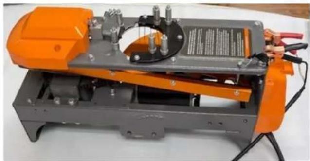

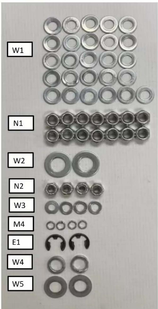
(B) Contents (cont.)
Cart Assembly
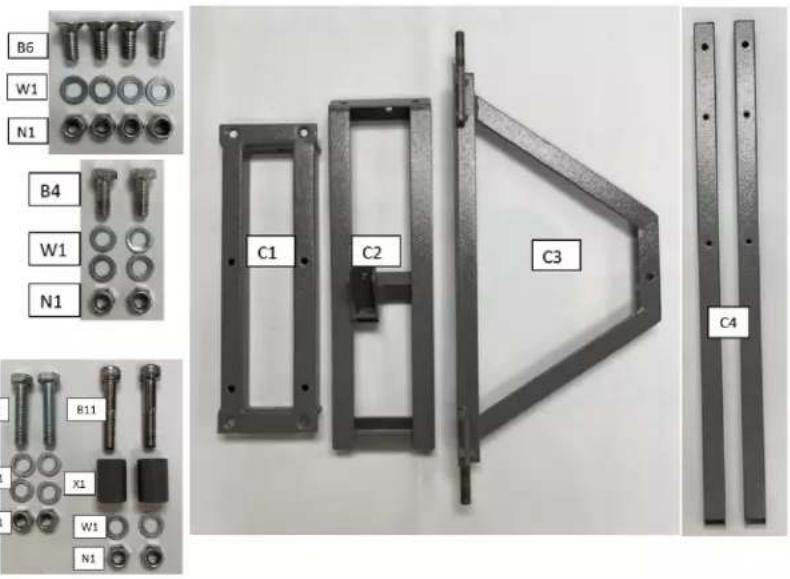
C1- Cart Top Support Bracket
C2- Cart Handle Support Bracket
C3- Cart Axel Bracket
C4- Cart Support Bracket
Battery Tray
BT1- Battery Tray


Handle Assembly
H1- Handle
S1- Hand Nut
B1-M10-1.5x60mm Bolt

(B) Contents (cont.)
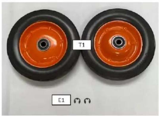
Wheel Assembly
T1- Wheel with Tires
E1- 18mmx9mm E Clip (2)
Main Body U Bracket
UB1 - Main Body U bracket


Handle Support U Bracket
UB2- Handle support U Bracket


(B) Contents (cont.)
Mainspring Assembly (pre-assembled)
S1- Hand Nut
S2- 20mm Washer
S3- Bushing Assembly
S4- Mainspring
S5- Main Spring Bolt

Attaching the Trap Body assembly
TB1- Trap Body Assembly
HB1- Hand Bolt (2)
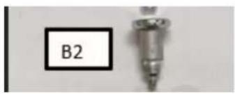
B2- Pull Pin




(B) Contents (cont.)
Safety Tube Assembly
A1 – Safety Tube Stud (2)
A2-Safety tube support (2)
A3- Button Head M5-.8x14mm (4)
A4 – Safety Tube

Magazine Assembly
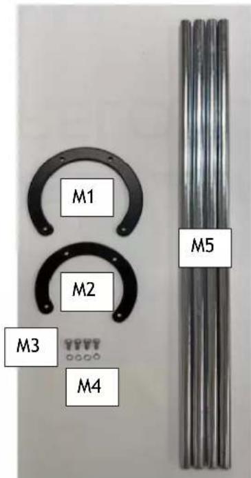
M1- 110mm Standard Top Plate
M2- 90mm MIDI Top Plate
M3- M5-.8x9.5mm Button Head (4)
M4- 8mm Lock Washer (4)
M5- Magazine Rod

(B) Contents (cont.)
Midi Adaptor
MA1- Midi adaptor
MA2- Slide plate Midi adaptor
MA3- M5-.8 x 9.5mm button head screw (3)
MA4- 10mm washer (3)
MA5- Magazine adaptor Stud


Extra Components
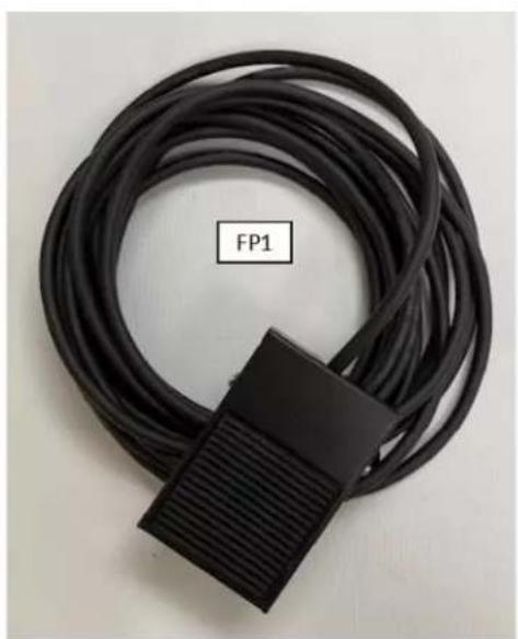
FP1- Foot Pedal with Cord GS1- Ground Stake 40923- Wireless receiver


(C) Assembly
CAUTION: PROVIDE AMPLE CLEARANCE AROUND THE TRAP. DO NOT OPERATE THE TRAP IN AN AREA THAT DOES NOT ALLOW SAFE (REAR) ACCESS TO THE TRAP AND THE ON/OFF/SAFE RELEASE SWITCH DURING LOADING AND USE.
1. Cart Assembly
A. The cart axel needs to be on the inside, as shown in figure 1.
B. The four center holes on the cart top support (C1) must be positioned towards the rear of the cart, away from the axel, as shown in figure 1.


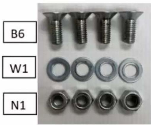
Figure 1
(C) Assembly (cont.)
2. Cart Assembly
A. Install two of the four panhead bolts (B6), two washers (W1), and two nuts (N1), as shown in figure 2. *Tighten finger tight for now. *

Figure 2
3. Cart Assembly
B. Assemble cart top support bracket (C,1) and cart handle support bracket (C2) as shown in figure 3. Then, using the other two pan head (B6) bolts, two washers (W1), and two nuts (N1), fasten the C1 and C2 together. *Tighten finger tight for now.

Figure 3
(C) Assembly (cont.)
4. Cart Assembly
A. Flip the cart assembly over, install the two bolts (B4), four washers (W1), and two nuts (N1) into the holes shown in figure 4. *Tighten finger tight for now.

5. Cart Assembly
A. Place both Round Spacers (X1) onto the cart bracket (C3) holes, as shown in Figure 5.

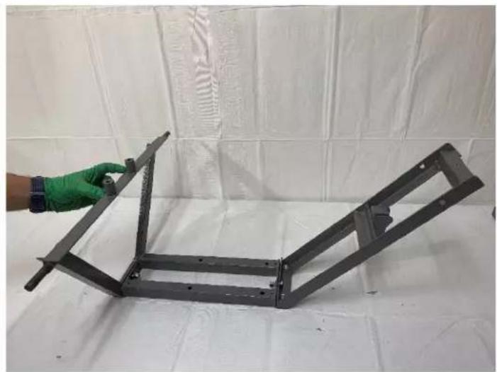
Figure 5
(C) Assembly (cont.)
6. Cart Assembly
A. Assemble cart support brackets (C4) onto round spacers (X1), and cart handle support brackets (C2).
B. The open hole on C4 needs to be faced up, as shown in figure 6.
C. Insert bolt (B11) through the large hole on C4, through the spacer, and assemble washer (W1) and nut (N1) on the bolt. *Tighten finger tight for now.*
D. Repeat steps A-C for the other cart support bracket (C4).


Figure 6
(C) Assembly (cont.)
7. Cart Assembly
A. Insert bolt (B10) through the opposite end of C4, use two washers (W1) and one nut N1) for each side. As shown in figure 7. *Tighten finger tight for now. *
B. Repeat step A for the other cart support bracket (C4).

Figure 7
8. Cart Assembly
A. Use a 13mm socket and 13mm wrench to tighten the previously assembled bolts in step 4.

(C) Assembly (cont.)
9. Battery Tray Assembly
A. Flip the cart assembly over and install the battery tray (BT1). Use four pan head bolts (B9), four washers (W3), and four nuts (N2). The BT1 should overhang on the left side if looking from the rear of the cart, as shown in figure 8. Use a 4mm Allen wrench and 11mm wrench to tighten the BT1 to the C4.


Figure 8
(C) Assembly (cont.)
10. Cart Assembly
A. Use a 5mm Allen wrench and 13mm wrench/socket to tighten all pan head bolts from steps 2 and 3.

11. Cart Assembly
A. Use a 6mm Allen wrench and 13mm wrench to tighten all bolts from step 6.
B. Use a 13mm wrench and a 13 socket to tighten all bolts from step 7.

(C) Assembly (cont.)
12. Handle assembly
A. Place handle (H1) into the handle slot on the cart handle support (C2). The hand nut (S1) and the bolt (B1) fasten the handle in position, as shown in figure 9.

Figure 9
13. Wheel Assembly
A. Assemble the wheel (T1) onto the axle shaft on the Cart Axle Bracket (C3) shown in figure 10. Make sure the round hub is facing outward. Once the wheel (T1) is on the shaft, push the E-Clip(E1) with a flat end of an Allen wrench.
B. Repeat step A for the opposite wheel (T1).


Figure 10

(C) Assembly (cont.)
14. Main Body U-Bracket Assembly
A. Place the Main Body U-Bracket (UB1) on top of the Cart Top Support Bracket (C1), then line the UB1 bracket up with the four bolt holes on top of the C1. See figure 11.
B. Ensure the welded nut on the Main Body U-Bracket (UB1) is on the backside towards the handle. See figure 11.
C. Assemble and tighten the four bolts (B10), eight washers (W1), and four nuts (N1) in the four holes of the Main Body U-Bracket (UB1). Install one washer on each side of the bolt (B10). Use a wrench/socket.
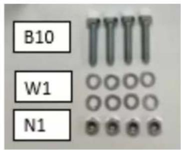


Figure 11

(C) Assembly (cont.)
15. Handle Support U-Bracket Assembly
A. Assemble the Trap Body Assembly (TB1) and the Handle Support U-Bracket (UB2), shown in Figure 12.
B. Install and tighten the four bolts (B5) and washers (four1) into four holes. Use a 13mm wrench.
a. Make sure the rounded notch is facing the rear of the; body see figure 12.
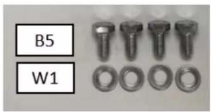


Figure 12
(C) Assembly (cont.)
16. Trap Body Assembly to Cart Assembly
A. Having another person for this step will make it much easier.
B. Attach the Trap Body Assembly (TB1) to the Cart Assembly using a shoulder bolt (B3) and a washer (W2), as shown in figure 13. The shoulder bolt (B3) and washer (W2) go in the rear hole, as shown in figure 13. Use an 8mm Allen wrench.
C. Repeat step B on the opposite side with another shoulder bolt (B3) and washer (W2).


Figure 13
(C) Assembly (cont.)
17. Hand Bolt Assembly
A. Install Hand Bolt (HB1), lock washer (W4), then a washer (W5) into the front hole of trap Body Assembly (TB1), as shown in figure 14.
B. Repeat step A with a Hand Bolt (HB1), lock washer (W4), then a washer (W5) on the opposite side.


Figure 14
(C) Assembly (cont.)
18. Pull Pin Assembly
A. Install Pull Pin (B2) into the welded nut on the Trap Body Assembly (TB1) by threading the Pull Pin into the left side of TB1 in the location shown in figure 15.
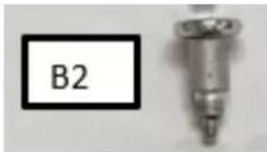
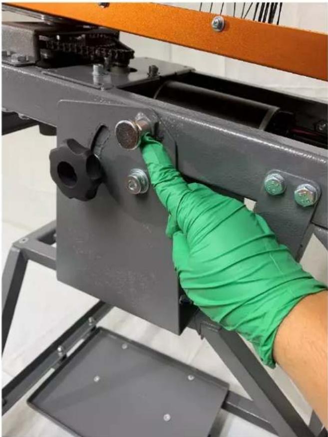
Figure 15
(C) Assembly (cont.)
19. Magazine Assembly
A. Assemble and tighten the 4 Magazine Rods (M5) to the 110mm Standard Top Plate (M1) with four button head screws (M3) and 4 Lock Washers (M4). It is shown in figure 16.


Figure 16
(C)Assembly (cont.)
20. Magazine Assembly on Trap Body
A. Insert the Magazine Assembly onto the Trap Body Assembly (TB1) via the four magazine studs on top of the top plate, as shown in figure 17.

Figure 17

WARNING: FAILURE TO KEEP HANDS AND BODY OUTSIDE THE THROWING ARM PATH INDICATOR AREA CAN RESULT IN SERIOUS INJURY OR DEATH FROM BEING STRUCK BY THE THROWING ARM DURING USE.
CAUTION: DO NOT LIFT TRAP BY THROWING ARM PATH INDICATOR TUBING OR THROWING ARM PATH INDICATOR TUBE SUPPORTS; THESE WERE NOT DESIGNED TO BE A LIFTING POINT
(C) Assembly (cont.)
21. Safety Tube Stud Assembly
A. Install and tighten the 2 Safety Tube Studs (A1) onto each rear threaded hole on the Trap Body Assembly (TB1), as shown in figure 18. Use a 12mm wrench.
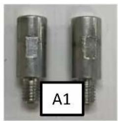

Figure 18
(C) Assembly (cont.)
22. Safety Tube Support
A. Install the safety tube supports (A2) by tightening two button head screws (A3) on each side of the Trap Body Assembly (TB1). The four holes are located on the Trap Body Assembly (TB1) front, as shown in figure 19.
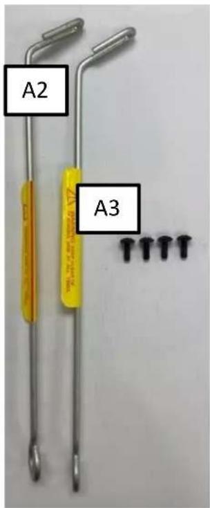

Figure 19
WARNING: FAILURE TO KEEP HANDS AND BODY OUTSIDE THE THROWING ARM PATH INDICATOR AREA CAN RESULT IN SERIOUS INJURY OR DEATH FROM BEING STRUCK BY THE THROWING ARM DURING USE.

CAUTION: DO NOT LIFT TRAP BY THROWING ARM PATH INDICATOR TUBING OR THROWING ARM PATH INDICATOR TUBE SUPPORTS; THESE WERE NOT DESIGNED TO BE A LIFTING POINT
(C) Assembly (cont.)
23. Safety Tube Assembly
A. Start by pushing the Safety Tube (A4) through the two Safety Tube Supports (A2) and then push the safety tube A4 onto the 2 Safety Tube Studs (A1). See Figure 20.


Figure 20
(C) Assembly (cont.)
In the following step (24 or 25), you can either connect the Wireless Receiver/Remote (40923) or the Foot Petal (FP1).
24. Wireless Receiver/ Remote Assembly
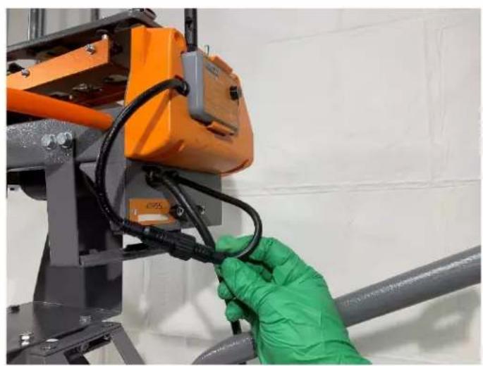
A. Snap the Wireless Receiver (40923) into the slot as shown in figure 21. Next, screw the female plug on the Wireless Receiver (40923) into the Trap Body Assembly (TB1) male plug, as shown in figure 22.


Figure 21 Fig

(C) Assembly (cont.)
25. Foot Pedal Assembly.
A. Plug the female plug on the Foot Petal (FP1) into the male plug on the Trap Body Assembly (TB1), shown in figure 23.
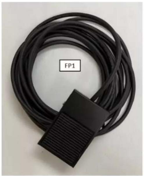

Figure 23
1. Assembly (cont.)
26. Ground Stake Assembly (Optional)
A. If needed, the Ground Stake (GS1) can be installed into the Cart Handle Support Bracket (C2) bottom hole, as shown in figure 24.


Figure 24
(D) 90mm Midi Conversion Assembly
FOLLOW THESE STEPS TO CONVERT THE TRAP TO THROW 90MM MIDI CLAYS INSTEAD OF 110MM STANDARD CLAYS.
Midi Parts Needed
MA1- Midi adaptor
MA2- Slide plate Midi adaptor
MA3- M5-.8 x 9.5mm button head screw (3)
MA4- 10mm washer (3)
Tools Needed
2 Phillips screwdriver
7MM Wrench
2.5MM Allen Wrench


1. Attaching the Magazine Studs
A. Remove the nut from the Magazine Stud (MA5) using a 7mm wrench and a 2.5mm Allen wrench, and then remove the bolt. See figure 25.
B. Insert and tighten the magazine stud bolt through the Midi adapter's bottom with Magazine Studs (MA1) hole, as shown in figure 26. Repeat for the opposite bolt. Use a 7mm wrench and a 2.5mm Allen wrench.
i. Make sure the shelf on the stud MA5 is on the bottom.

Figure 25 Fi
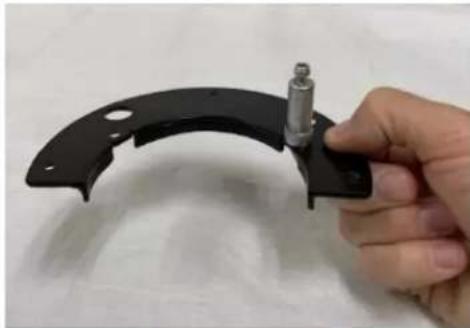


Figure 27
(D) 90mm Midi Conversion Assembly
1. Release the tension of Main Spring.
C. Release the tension of the mainspring. (REFER TO pages 45-47)
D. Slowly pull the Main Spring Hand Nut (S1) while rotating the throwing arm to the 12 o'clock position, as shown in Figure 28-30.

Figure 28

Figure 29
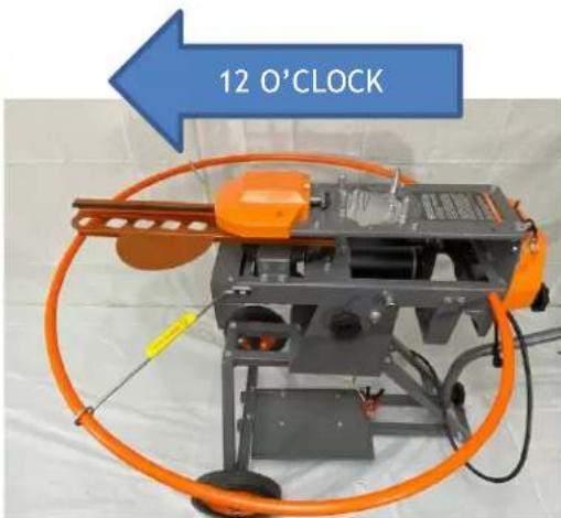
Figure 30
(D) 90mm Midi Conversion Assembly
2. Slide Plate Midi Assembly
A. The throwing arm at the 12 O'clock position Places the Slide Plate Midi adapter (MA2) tab into the slot on the slide plate, as shown in figure (31).


Figure 31
3. Midi Adapter Assembly
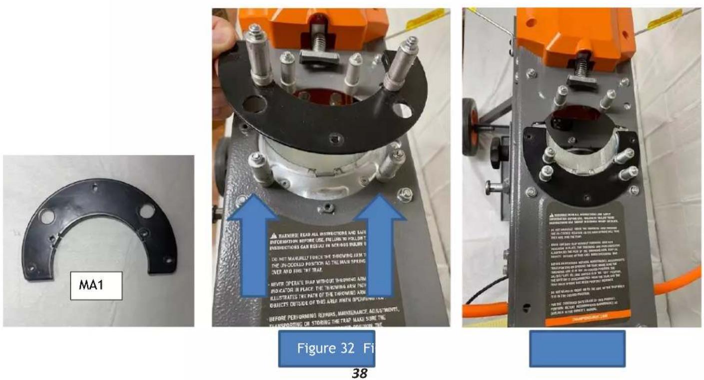
A. Insert the Midi Adapter with Magazine Studs over the two rear 110mm magazine studs as shown in Figures 32-33.
(D) 90mm Midi Conversion Assembly
4. Midi Adapter Assembly
A. Secure the Midi Adapter with Magazine Studs (MA1) to the Trap Body Assembly (TB1) using the 3 Button Head Screws (MA3) and Washers (MA4), as shown in figure 34. Use a #2 Phillips Screwdriver.


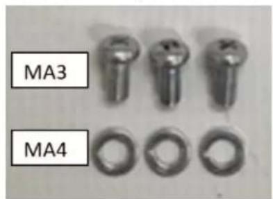

Figure 34
5. Remove Standard 110mm Magazine Top Plate
A. Remove the Standard 110mm Magazine Top Plate (M1) from the 4 Magazine Rods (M5) by loosening the 4 Button Head Screws, as shown in figure 35. Use #2 Phillips screwdriver.
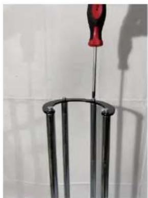
Figure 35
(D) 90mm Midi Conversion Assembly
6. 90mm Midi Top Plate Assembly.
A. Install the 90mm Midi Top Plate (M2) using the same 4 Magazine Rods (M5) by tightening the 4 Button Head Screws, as shown in figure 36. Use #2 Phillips screwdriver.

Figure 36
7. Install the 90mm Midi Magazine
A. Install the 4 Magazine Rods (M5) over the two front Magazine Studs (MA5) and the two magazine studs on the Midi Adapter (MA1). The open end of the 90mm Midi Top Plate (M2) is faced toward the rear of the trap, as shown in figure 37.
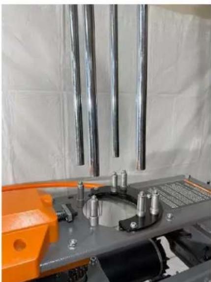
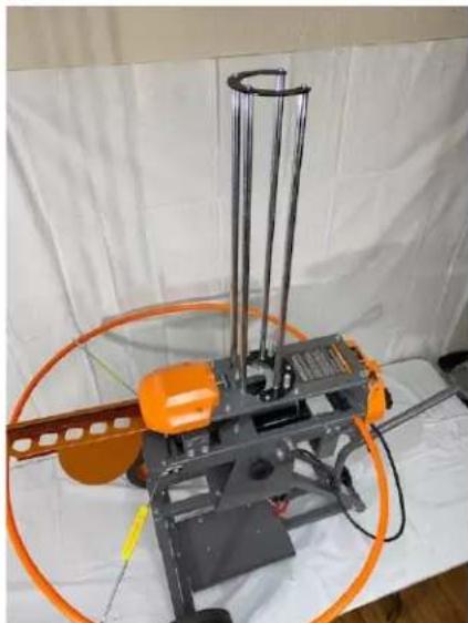
Figure 37
(E) Setup

WARNING: MAKE SURE THAT THE "ON-OFF-SAFE RELEASE" SWITCH IS SET TO THE "OFF" POSITION BEFORE CONNECTING POWER TO THE TRAP. AN UNINTENTIONAL DISCHARGE OF THE TRAP COULD CAUSE SERIOUS INJURY OR DEATH.
DO NOT OPERATE THE TRAP IN AN AREA THAT DOES NOT ALLOW SAFE (REAR) ACCESS TO THE TRAP AND THE ON/OFF/SAFE RELEASE SWITCH DURING LOADING AND USE.
b. Remove the Arm Retention Pin (SP1) from the top plate and put it in the rear storage hole. (If you have forgotten to remove the retention pin and the throwing arm is wedged against the retention pin, release the tension on the mainspring. DO NOT lift the retention pin with force. If the arm is stuck, the throwing arm will immediately cycle and cause injury or damage to the trap.)
c. Remove wire ties from foot pedal release cable and attach plug end to plug on the trap. Place foot pedal switch on firm ground.

- For additional stability of the trap, the ground stake can be placed through the rear hole of C2 (Handle Support Bracket) and driven into the ground.
- Connecting the red battery leads to the positive (+) terminal and the black battery leading to the negative (-) terminal of a charged deep cycle 12V Battery.
- Before loading targets into the trap, turn the On/Off/Safe Release switch to the "ON" position and check the function of the trap by depressing the foot pedal. If the trap does not function correctly, see section "VI. ADJUSTMENTS" on page 43.
Note: It is acceptable to dry fire the trap (fire the trap without launching a target). This will not damage the trap.
- Disconnect the battery leads from the battery.
V.Operation
WARNING: DO NOT STAND IN FRONT OF OR IN THE PATH OF THE THROWING ARM! SERIOUS INJURY OR DEATH MAY RESULT!
-
The safety tube must be mounted properly before using the trap.
-
Ensure the trap is located to allow ample clearance around the machine and provides safe access to the rear of the trap during operation. The trap must be located so that the user has safe access to the rear to operate the On/Off/Safe Release switch and reload the trap.
-
Ensure that the On/Off/Safe Release switch is in the "OFF" position and the arm is in the uncocked position.
-
Place six (6) targets into the magazine and hold them flat. Pull back on Target Retainer Loading Bar if the Rubber Target Retainer interferes with the targets.

-
Release the Target Retainer Loading Bar if it was being held. The rubber target retainer should be pressing on the 2nd target. Release the targets. Continue to load targets into the magazine column.
-
After the targets are loaded, connect the trap to a fully charged 12V battery, ensuring the remote release cord is safely away from and behind the trap.
-
Turn the On/Off/Safe Release switch to the "ON" position.
-
The trap should cock the throwing arm and, at the same time, drop one target onto the throwing arm as it is cocking.
-
Activate the Foot Pedal Switch, and the Freedom Bird Trap will release the throwing arm (launching the target), re-cock the throwing arm, and drop another target onto the throwing arm.
WARNING: IF THERE IS A TARGET ON THE THROWING ARM, SAFE RELEASING THE THROWING ARM WILL THROW THE TARGET. DO NOT STAND IN FRONT OF THE TRAP.
- When reloading the trap, first move the ON/OFF/SAFE RELEASE switch to the "SAFE RELEASE" position momentarily to un-cock the throwing arm. Then, allow the switch to return to the "OFF" position. The trap magazine can then be safely reloaded with targets from the rear of the trap.
VI. Adjustments
(A) Throwing Arm Limit Switch

WARNING: BEFORE MAKING ANY ADJUSTMENTS MAKE SURE THE THROWING ARM IS IN THE UNCOCKED POSITION, THE ON/OFF/SAFE RELEASE SWITCH IS IN THE "OFF" POSITION, AND THE BATTERY IS DISCONNECTED FROM THE TRAP! DO NOT MANUALLY FORCE THE THROWING ARM THROUGH THE UNCOCKED POSITION AS THE MAINSPRING WILL TAKE OVER AND FIRE THE TRAP, POTENTIALLY CAUSING SERIOUS INJURY OR DEATH.
The machine is set at the factory. Only adjust the limit switch if a target doesn't drop onto the throwing arm as the throwing arm is cocking, or the throwing arm continuously fires. TEST MACHINE FIRST WITHOUT ANY TARGETS.
*If you "Dry Fire" test with the wireless remote, the throwing arm could cycle twice. The receiver is electronically programmed to weigh the clay on the throwing arm. *
The limit switch controls the stop position of the throwing arm during the trap cocking cycle. The limit switch is located under the trap near the front. The front cover can be removed to gain easier access to the switch. Replace cover after adjusting switch.
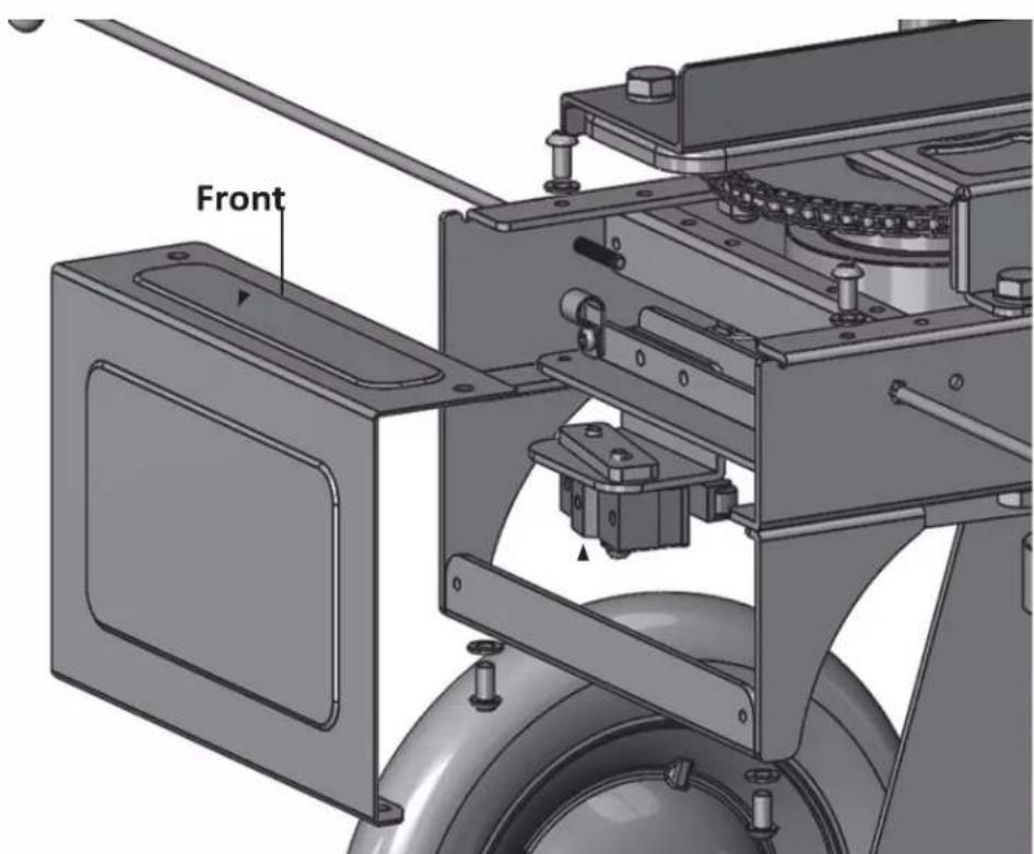
Limit Switch
Adjustments to the limit switch are made by loosening the two mounting screws and moving the switch slightly (small movements will make a big difference):
- Pivot the switch slightly towards the rear of the trap to make the arm stop further away from the edge of the main body.
- Pivot the switch slightly towards the front of the trap to make the arms stop closer to the edge of the main body.
- Retighten the mounting screws after adjusting the switch.
- Adjust switch so that a target drops onto the throwing arm as the arm is cocking. With the ON/OFF/SAFE RELEASE switch set to "on," the tip of the arm should stop within 2.0" to 4.0" from the edge of the top plate of the trap. The opening in the sliding plate should lineup with the opening in the top plate and allow a target to drop.

WARNING: ADJUSTING THE ARM TO STOP AT A POINT TOO FAR AWAY FROM THE TRAP BODY CAN RESULT IN A DELAYED-RELEASE OR IMPROPER LOADING AND TARGET BRAKING, WHICH COULD RESULT IN PERSONAL INJURY OR DEATH FROM THE THROWING ARM.

WARNING: ADJUSTING THE ARM TO STOP AT A POINT TOO CLOSE TO THE TRAP BODY CAN RESULT IN THE ARM CONTINUOUSLY FIRING OR FIRING UNEXPECTEDLY, WHICH COULD RESULT IN PERSONAL INJURY OR DEATH FROM THE THROWING ARM.


(B) Elevation Adjustment

WARNING: BEFORE MAKING ANY ADJUSTMENTS, MAKE SURE THE THROWING ARM IS IN THE UNCOCKED POSITION, THE ON/OFF/SAFE RELEASE SWITCH IS IN THE "OFF" POSITION, AND THE BATTERY IS DISCONNECTED FROM THE TRAP. DO NOT MANUALLY FORCE THE THROWING ARM THROUGH THE UNCOCKED POSITION AS THE MAINSPRING WILL TAKE OVER AND FIRE THE TRAP, POTENTIALLY CAUSING SERIOUS INJURY OR DEATH.
- To adjust the elevation, slightly loosen the two Hand Bolts (HB1) (one on each side of the trap).
- Pull the head of the Pull Pin (B2) while pressing down on the rear of the trap; once the trap starts to move, let go of the Pull Pinhead, and it will stop at the next available throwing angle. Once you have reached the desired angle from 0-50 degrees, retighten the Hand Bolts (HB1). The hand bolts must be tight before cycling the trap, limiting the vibration and preventing damage to the pull pin. See figure (38)
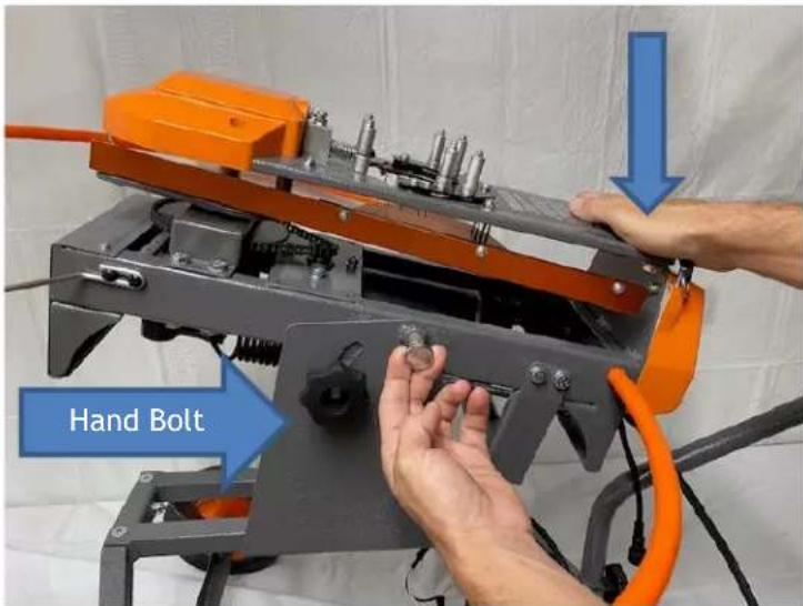
Figure 38
(C) Distance Adjustment

WARNING: BEFORE MAKING ANY ADJUSTMENTS, MAKE SURE THE THROWING ARM IS IN THE UNCOCKED POSITION, THE ON/OFF/SAFE RELEASE SWITCH IS IN THE "OFF" POSITION, AND THE BATTERY IS DISCONNECTED FROM THE TRAP. THIS TRAP IS CAPABLE OF THROWING TARGETS A DISTANCE OF UP TO 90 YARDS. USE ONLY IN AREAS WHERE THERE IS NO RISK OF INJURY TO ANOTHER PERSON OR CAUSING OTHER DAMAGE.
WARNING: DO NOT MANUALLY FORCE THE THROWING ARM THROUGH THE UNCOCKED POSITION AS THE MAINSPRING WILL TAKE OVER AND FIRE THE TRAP, POTENTIALLY CAUSING SERIOUS INJURY OR DEATH.
To adjust the tension of the mainspring, follow these steps for max tension or un-cocked position.
- Put the Freedom Bird into the zero-degree elevation setting. Remove the Handle (H1) from the Cart Handle Support Bracket (C2) by unthreading the Hand Nut(S1). Place the Handle (H1) between the Handle Support U-Bracket (HB2) and the back of the trap. See figure (39). The hook should be on both sides of the mainspring bolt and latched on the pivot stud of the mainspring bolt, as shown in figure (39).

Figure 39

2. Max Spring Tension
a. To adjust to max spring tension, press down and hold on to the handle with one hand (H1). Next, pull the mainspring pulling tension on the spring; with your other hand, thread the hand Nut (S4) in until the Hand Nut (S4) stops. When the S4 has no more threads, the spring will be at max tension. See figure (40).

Figure 40
-
Un-Cocked position
-
Use caution during this procedure. To adjust the mainspring to the un-cocked position, start using the safe release switch, firing the trap one time. Next, use the handle to release the spring tension by pressing down on the handle with one hand; with your other hand, unthread the hand nut (s4) until the mainspring bolt is threaded into the back of the hand nut. The trap is now in the un-cocked position. (see figure 41)
a. Place the Arm Retention Pin (SP1) in the top plate pinhole. Then rotate the throwing arm by hand until it contacts the arm retention pin. See figure (42).

Figure 41

Figure 42
VII. Transportation and Storage

WARNING: BEFORE MAKING ANY ADJUSTMENTS, MAKE SURE THE THROWING ARM IS IN THE UNCOCKED POSITION, THE ON/OFF/SAFE RELEASE SWITCH IS IN THE "OFF" POSITION, AND THE BATTERY IS DISCONNECTED FROM THE TRAP. UNINTENTIONAL FIRING OF THE TRAP CAN CAUSE INJURY OR DEATH FROM BEING STRUCK BY THE THROWING ARM.

WARNING: DO NOT TRANSPORT OR STORE TRAP WITH MAINSPRING IN COCKED POSITION OR BATTERY ATTACHED. UNINTENTIONAL FIRING OF THE TRAP CAN CAUSE SERIOUS INJURY OR DEATH FROM BEING STRUCK BY THE THROWING ARM. FOR ADDITIONAL SAFETY AND TO PREVENT UNWANTED DAMAGE, REMOVE SPRING TENSION AND PLACE THE THROWING ARM IN THE 6 O'CLOCK POSITION, AND SECURE THE THROWING ARM WITH A RETAINING PIN.

WARNING: NEVER REMOVE THE SAFETY TUBE UNLESS MAINSPRING TENSION HAS BEEN RELEASED FIRST. NEVER OPERATE TRAP WITHOUT SAFETY TUBE. SERIOUS INJURY OR DEATH CAN RESULT.

WARNING: DO NOT MANUALLY FORCE THE THROWING ARM THROUGH THE UNCOCKED POSITION AS THE MAINSPRING WILL TAKE OVER AND FIRE THE TRAP, POTENTIALLY CAUSING SERIOUS INJURY OR DEATH.
To put the Freedom Bird trap in the transportation or storage configuration, follow these instructions:
- Put the Freedom Bird into the zero-degree elevation setting. Remove the Handle (H1) from the Cart Handle Support Bracket (C2) by unthreading the Hand Nut(S1). Place the Handle (H1) hook between the Handle Support U-Bracket (HB2) and the back of the trap. See figure (43). The hook should be on both sides of the mainspring bolt and latched on the pivot stud of the mainspring bolt, as shown in figure (43).
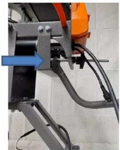
Figure 43

- Use caution during this procedure. To adjust the mainspring to the un-cocked position, start using the safe release switch, firing the trap one time. Next, use the handle to release the spring tension by pressing down on the handle with one hand; with your other hand, unthread the hand nut (s4) until the mainspring bolt is threaded into the back of the hand nut. The trap is now in the un-cocked position. (see figure 44)

Figure 44

- Install the retention pin in the top plate retention pinhole and pinhole throwing arm to contact the retention pin.
- Remove magazine assembly by sliding the magazine rods off the magazine studs.
- If necessary, detach the safety tube (A4) from both safety tube studs (A2), and both Safety Tube Supports (A1).
- If necessary, remove the battery.
- Store trap indoors away from the elements and out of children's reach.
VIII. Troubleshooting
THE THROWING ARM IS STUCK ON THE RETENTION PIN
- Release the tension on the mainspring, DO NOT lift the retention pin with force if the arm is still throwing arm will immediately cycle and cause injury or damage to the trap.
THE MOTOR WILL NOT START
- The "ON-OFF-SAFE RELEASE" switch on the trap is in the "OFF" position.
- The circuit breaker on the rear of the trap is tripped - determine this before resetting. The battery is inadequately charged - recharge battery.
- Electrical connections are loose, disconnected, or damaged.
- The battery is not connected correctly – check battery wires for correct polarity.
- The motor is burned out.
- The throwing arm is blocked from rotating.
- The "ON-OFF-SAFE RELEASE" switch is broken.
- The relay is burned out.
THE MOTOR RUNS BUT DOES NOT COCK THROWING ARM
- The battery is inadequately charged - recharge battery.
- The drive chain is broken.
- The one-way clutch bearing has slipped.
THE TRAP COCKS, BUT DOES NOT FIRE
- The "ON-OFF-SAFE RELEASE" switch is in the "OFF" position.
- Electrical connections are loose, disconnected, or damaged.
- The foot pedal switch or connection is damaged.
THE THROWING ARM STOPS, BUT A TARGET DOESN'T DROP
- The limit switch is damaged or out of adjustment.
- Adjust the limit switch, so the arm stops closer to the edge of the top plate.
- Test with a different brand or shipment of clay targets.
THE THROWING ARM DOES NOT STOP AND CONTINUES FIRING
- The throwing arm limit switch is damaged or out of adjustment.
- Adjust the limit switch, so the arm stops farther away from the edge of the top plate.
- The foot pedal switch stuck.
- Foot pedal switch cord wires are shorted together.
- The relay is burned out.
EXCESSIVE TRAP NOISE OR VIBRATION
- Check all bolts to make sure they are tight.
- The mainspring is loose, causing a "spring slap." First, check to ensure the mainspring bolt is at least at the minimum position mark located on the mainspring bolt.
THE CLAYS CONSTANTLY BREAK
- The Limit switch is out of adjustment.
- The whiskers that hold the clay in position once they drop onto the arm are bent or broken off, which would cause the clays to move out of position.
- The rubber on the throwing arm, which prevents the clays from breaking, is damaged.
- The throwing arm is bent or damaged.
IX. Maintenance

WARNING: BEFORE PERFORMING ANY MAINTENANCE ON THE TRAP, MAKE SURE THAT THE THROWING ARM IS IN THE UNCOCKED POSITION, THE ON/ OFF/SAFE RELEASE SWITCH ON THE TRAP IS IN THE "OFF" POSITION, AND THE BATTERY HAS BEEN DISCONNECTED.
DO NOT MANUALLY FORCE THE THROWING ARM THROUGH THE UNCOCKED POSITION AS THE SPRING WILL TAKE OVER AND FIRE THE TRAP. POTENTIALLY CAUSING SERIOUS INJURY OR DEATH.
| Preventive Maintenance Action | Frequency |
| Remove dust, dirt, and target debris with a soft brush | Before every use |
| Check to mount to ensure they remain tight | Every month or 8,000 cycles |
| Lubricate moving parts with a good quality lubricating oil such as HOPPE'S® Black Gun Grease | Every month or 8,000 cycles |
| Disconnect Battery | After every use |
WARNING: ALWAYS CHECK THAT THE WIRING, THROWING, MECHANISM, SAFETY FEATURES ARE IN GOOD AND ON, AND THE TRAP IS FREE OF DEBRIS BEFORE EVERY USE. FAILURE TO PROPERLY MAINTAIN THIS PRODUCT COULD INCREASE THE RISK OF DEATH OR SERIOUS INJURY.
X. Replacement Parts
Parts are available by calling Champion Customer Service Department at (800) 533-5000.
XI. Appendix: Wireless Remote Accessory Instructions

WARNING: TO AVOID SERIOUS INJURY OR PROPERTY DAMAGE, THOROUGHLY READ INSTRUCTIONS BEFORE USING.
Features of the Champion® Wireless Remote Release system include:
- Battery-powered and remote, high-pact plastic case.
- Long transmission range (100 yds)
- Single Release system that will work with multiple Receiver units.
- User settable delay from 0-15 seconds.
- Quick and easy installation.

FCC NOTE:
This device complies with Part 15 of the FCC Rules. Operation is subject to the following two conditions: (1) This device may not cause harmful interference, and (2) this device must accept any interference received, including interference that may cause undesired operation.
NOTE: This equipment has been tested and found to comply with the limits for a Class B digital device, according to Part 15 of the FCC Rules. These limits are designed to provide reasonable protection against harmful interference in a residential installation. This equipment generates, houses, and can radiate radio frequency energy and, if not installed and used in accordance with the instructions, may cause harmful interference to radio communications. However, there is no guarantee that interference will not occur in a particular installation. If this equipment does cause harmful interference to radio or television reception, which can be determined by turning the equipment off and on, the user is encouraged to try to correct the interference by one of the following measures:
- Reorient or relocate the receiving antenna.
- Increase the separation between the equipment and receiver.
- Connect the equipment into an outlet on a circuit different from that to which the receiver is connected.
- Consult the dealer or an experienced radio/TV technician for help.
Shielded interface cable must be used with the equipment in order to comply with the limits for a digital device pursuant to Subpart B of Part 15 of FCC Rules.
FCC Caution: Any changes or modifications not expressly approved by the party responsible for compliance could void the user's authority to operate this equipment.
This Transmitter must not be co-located or operating in conjunction with any other antenna or Transmitter.
Radiation Exposure Statement:
The product complies with the FCC portable RF exposure limit set forth for an uncontrolled environment and is safe for the intended operation as described in this manual. Further RF exposure reduction can be achieved if the product can be kept as far as possible from the user's body or when set to lower output power if such function is available.
Industry Canada Statement
This device complies with Industry Canada's license-exempt RSSs. Operation is subject to the following two conditions: (1) This device may not cause interference, and (2) This device must accept any interference, including interference that may cause undesired operation of the device.
Radiation Exposure Statement:
This device complies with the Industry Canada portable RF exposure limit set forth for an uncontrolled environment and is safe for the intended operation as described in this manual. Further RF exposure reduction can be achieved if the product can be kept as far as possible from the user's body or if the device is set to a lower output power if such function is available.
Safety
- Do not stand in front of the trap when it is in the cocked position. Accidental release of the target and throwing arm can cause serious injury or death!
- Before installing the Wireless Receiver on the trap, make sure that the throwing arm is in the uncocked position, the trap is in the off position and the trap is disconnected from the battery.

WARNING: DO NOT MANUALLY FORCE THE THROWING ARM THROUGH THE UNCOCKED POSITION AS THE MAINSPRING WILL TAKE OVER AND FIRE THE TRAP, POTENTIALLY CAUSING SERIOUS INJURY OR DEATH.
- All personnel operating the trap should be thoroughly familiar with the operating instructions and the safety issues relating to the trap.
- Do not leave the rap in the cocked position. Accidental release of the throwing arm can occur.
- Keep hands and body away from the trap and throwing arm path while the trap is operating.
- Always disconnect the power or turn off trap when unattended, not in, use, or performing maintenance.
• Always check that others are safe before releasing the trap.
• Always stay outside of the safety tube zone. - Never store the remote in pockets with the battery installed. Unintentional pressing of the buttonwill cause the trap to release.
• Before working on the trap, ensure the battery is removed from the remote.

WARNING: THOROUGHLY READ INSTRUCTIONS BEFORE INSTALLING OR OPERATING THE WIRELESS REMOTE! FAILURE TO FOLLOW SAFETY RULES CAN RESULT IN SERIOUS INJURY OR DEAT
Contents
- Wireless Receiver (attach included antenna to the top of the receiver).
• Wireless Remote Transmitter
• Adhesive "Hook & Loop" Mounting Pad
• 12 Volt Type A23 Battery for Transmitter (Included, not shown)

Features and Descriptions
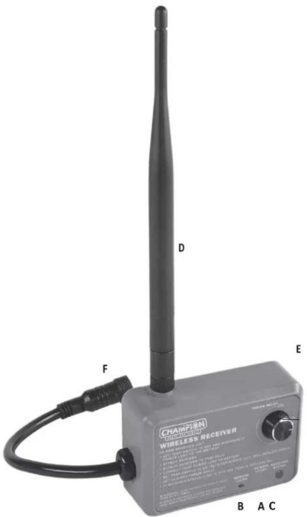
Wireless Receiver
A) Remote Learn Button
- Initiates pairing (programming) of Receiver and Wireless Remote Transmitter.
B) Remote Learn Light
- Flashes slowly to indicate the receiver is ready to learn the Wireless Remote Transmitter. - Flashes rapidly three times the s the hen receiver has learned the Wireless Remote Transmitterto confirm the received signal.
c) Receiver Status the Light
- When the LED is green, the receiver is powered on and will accept asignal from the remote.
• As soon as a signal is received, the status will turn red until the trap fires. - Once the trap is fired, the light will turn back to green.
D) Remove Antenna
- An antenna must be attached for properoperation.
E) Throw Delay
- Adjusts the length of delay (range 0-15 seconds) for the trap to fire after the receiver receives a signal from the Wireless Remote Transmitter.
F) 12V Power Connector and Output Connector
- Allows the user to attach the receiver quickly and easily to the trap.
Wireless Remote Transmitter
G) Transmitter Button (Throw Button)
- Pressing this button will transmit the command to activate the output to any Receiver which has learned the Wireless Remote Transmitter and is within range of the Transmitter.
H) Signal Light
• Illuminates whether n signal is being transmitted.
1) Battery Compartment Cover
- Remove to install/replace the A23 battery.


Installation

WARNING: MAKE SURE THAT THE THROWING ARM IS IN THE UNCOCKED POSITION, THE TRAP IS IN THE OFF POSITION, THE MAINSPRING IS REMOVED, AND THE TRAP IS DISCONNECTED FROM THE BATTERY. THE FOOT PEDAL MUST BE REMOVED FROM THE TRAP BEFORE USING A REMOTE TRANSMITTER/RECEIVER TO ACTIVATE THE TRAP.

WARNING: DO NOT MANUALLY FORCE THE THROWING ARM THROUGH THE UNCOCKED POSITION AS THE MAINSPRINGNG WILL TAKE OVER AND FIRE THE TRAP, POTENTIALLY CAUSING SERIOUS INJURY OR DEATH.
Mounting the Receiver
- Perform a safe release, turn the power off, disconnect the battery, and empty the trap magazine.
- Screw the receiver's 12V Power and Output Connector male plug (F) onto the female 12V Power and Output Connector. The receiver should be mounted to the back of the, with top of the Receiver flush with trap, using thereceiver hooks on the trap.
Programming (Pairing Receiver and the Transmitter)
Before operating, the receiver(s) (see note below regarding controlling multiple Receivers) will need to be programmed to respond to the Wireless Remote Transmitter you will be using.
- Install a 12V A23 Battery in the Wire Receiver Transmitter.
- The receiver should be mounted and installed per "Installation" directions above.
- Connect trap to the battery and turn trap to "ON" (Trap must be turned "ON" to provide power to the receiver). This will arm the trap, and the throwing arm will move into the cocked position. The Receiver Status Light (C) on the Receiver will be green, indicating it is powered "ON" and will accept a signal from the Wireless Remote Transmitter. Press the Remote Learn Button (A) to enter the learning mode. Remote Learn Light (B) will slowly flash to indicate the receiver is ready to learn the Wireless Remote Transmitter's signal. Next, quickly press the Throw Button (G) on the Wireless RemoteTransmitter Receiver to learn the signal. Once the receiver has learned the signal, the Remote Learn Light (B) will flash rapidly three times, confirming the receiver has been programmed to the Wireless Remote Transmitter.
- Verify the Wireless Remote Transmitter and Receiver are programmed by setting Throw Delay (E) to 0 seconds and press Throw Button (G). If Programming were successful, the trap would fire if therapy does not fire when Throw Button (G) is pressed perform programming process again or set troubleshooting section on next page.
- Perform safe release on trap and disconnect trap from 12V Battery.
NOTE: Multiple receivers can be assigned to one (1) transmitter. This will allow multiple traps to be controlled simultaneously from one remote. Use the Throw Delay knob (E) on each receiver to set the desired delay time (0-15 sec) between traps.
WARNING: BEFORE PAIRING THE TRANSMITTER TO A NEW RECEIVER, ENSURE THAT THE BATTERY IS DISCONNECTED ON ALL TRAPS USED WITH ANY PREVIOUSLY PAIRED RECEIVER.
Operation
- Set Mainspring on the trap.
- Connect trap to 12V Battery
- Set trap main power switch to "ON." Receiver Status Light (C) will light up green to indicate thereceiver is activated and ready to receive signals from the Transmitter.
- Repeat above steps 1-3 for additional traps/receivers if operating multiple traps from theTransmitter.
- Operate trap (s) by pushing Throw Button (G) on Wireless Remote Transmitter to launch target from the trap (s). The Wireless Remote Transmitter will now function each time you press the Throw button (G). Thus, each push of the Throw Button (G) will launch every active trap within range. Note: If Throw Button (G) is pressed while a Receiver has a Throw Delay time set, it will only fire once within the delay interval.
To disarm the receiver (s) and safely stop trap (s) operation:
- Perform safe release on trap and disconnect trap from 12V Battery.
To reinstall foot pedal if desired:
- Disconnect the receiver's 12V Power and Output connector (F) from the trap.
- Remove receiver from the trap and attach the foot pedal to 12V Power and Output connector on the trap.
Troubleshooting

WARNING: MAKE SURE THAT THE THROWING ARM IS IN THE UNCOCKED POSITION AND THE TRAP IS IN THE OFF POSITION BEFORE MAKING ANY ADJUSTMENTS TO THE RECEIVER.

WARNING: DO NOT MANUALLY FORCE THE THROWING ARM THROUGH THE UNCOCKED POSITION AS THE MAINSPRING WILL TAKE OVER AND FIRE THE TRAP, POTENTIALLY CAUSING SERIOUS INJURY OR DEATH.
The Wireless Remote Transmitter Signal Light (H) is Flashing
- Replace the Battery in the Wireless Remote Transmitter.
The Wireless Remote Transmitter Does Not Operate the Receiver
- Check that the Receiver Status light (C) is on and green.
- Check that the Signal Light (H) on the Wireless Remote Transmitter turns red when depressing the Throw Button (G).
- Reprogram the Wireless Remote Transmitter to the receiver (see Programming).
- Check battery orientation or replace the battery in the Wireless Remote Transmitter.
Reduced Operating Range
- Replace the Battery in the Wireless Remote Transmitter with a new A23 battery.
The wireless remote system uses radio-based communication between the remote and the receiver. As in all radio-based communication, performance will vary based on the environment and configuration of the system.
If the Transmitter fails to trigger the receiver, the following steps may help improve operation:
- Move the Wireless Remote Transmitter closer to the receiver. This will also help to confirm that the Wireless Remote Transmitter and Receiver are programmed and functioning properly.
- Press the Throw Button (G) on the Wireless Remote Transmitter for one to two seconds.
- Hold the Wireless Remote Transmitter with antenna vertical (pointed upwards to the sky). Do not point the antenna at the receiver.
- Hold the Wireless Remote Transmitter higher.
• Make sure there is no structure between the Wireless Remote Transmitter and the receiver. - Move the receiver to an elevated position to place the antenna at a greater height.

Warranty:
WARRANTY CERTIFICATE
Congratulations on the purchase of your new CHAMPION FREEDOM BIRD AUTO-FEED TRAP.
Your new FREEDOM BIRD AUTO-FEED TRAP is warranted to be free from defects in material or workmanship for six (6) months from the date of purchase. This warranty is extended only to the original consumer purchaser. Should you believe that your CHAMPION FREEDOM BIRD AUTO-FEED TRAP is defective in material or workmanship, you should contact the CHAMPION TRAPS & TARGETS Customer Service Department via phone at 800-533-5000. In the event a warrantyrepair is required, all parts will be provided at no charge. THIS WARRANTY DOES NOT COVER DEFECTS OR DAMAGE RESULTING FROM: CARELESSNESS, MISUSE, IMPROPER INSTALLATION, MODIFICATION, OR NORMALWEAR AND TEAR.
FOR THIS WARRANTY TO BE IN EFFECT, YOU MUST PROVIDE PROOF OF PURCHASE WITHIN 30 DAYS. WARRANTY SERVICES CANNOT BE PROVIDED WITHOUT MEETING THE ABOVE REQUIREMENT. Retain this warranty certificate for future reference. THE IMPLIED WARRANTIES OF MERCHANTABILITY AND FITNESS FOR A PARTICULAR PURPOSE ARE LIMITED TO THE DURATION OF THIS LIMITED WARRANTY.
CHAMPION TRAPS AND TARGETS ARE NOT LIABLE FOR DAMAGES IN EXCESS OF THE PURCHASE PRICE OF THE PRODUCT, AND UNDER NO CIRCUMSTANCE SHALL CHAMPION TRAPS AND TARGETS BE LIABLE FOR CONSEQUENTIAL OR INCIDENTAL DAMAGES. HOWEVER, SOME STATES DO NOT ALLOW LIMITATIONS ON IIN INCIDENTAL OR CONSEQUENTIAL DAMAGES, SO THE ABOVE LIMITATION OR EXCLUSION MAY NOT APPLY TO YOU.
The above warranty provides the sole and exclusive warranty for the customer of the defect in material or workmanship in the CHAMPION Freedom Bird™ AUTO-FEED TRAP. This warranty gives you specific legal rights, and you may also have other rights which vary from State to State.
XIII. CONTACT INFORMATION
Champion Traps and Targets
605 ORO DAM BLVD E.
OROVILLE, CA 95965
Toll-Free (800)533-5000
Internet: www.championtarget.com
Email: rcbs.tech@vistaoutdoor.com

Champion Traps and Targets
9200 Cody St.
Overland Park, KS 66214
Toll-Free (800) 379-1732
Internet: www.championtarget.com
Email: tech.expert@vistaoutdoor.com
- FREEDOM BIRD AUTO-FEED TRAP
- INSTRUCTION MANUAL
- TABLE OF CONTENTS
- SECTION
- PAGE
- INTRODUCTION
- SAFETY
- CONVENIENCE
- PERFORMANCE
- TOOLS REQUIRED FOR ASSEMBLY
- TOOLS
- ASSEMBLY AND INSTALLATION
- UNPACKING
- CONTENTS (CONT.)
- CART ASSEMBLY
- BATTERY TRAY
- HANDLE ASSEMBLY
- WHEEL ASSEMBLY
- MAIN BODY U BRACKET
- HANDLE SUPPORT U BRACKET
- MAINSPRING ASSEMBLY (PRE-ASSEMBLED)
- ATTACHING THE TRAP BODY ASSEMBLY
- SAFETY TUBE ASSEMBLY
- MAGAZINE ASSEMBLY
- MIDI ADAPTOR
- EXTRA COMPONENTS
- ASSEMBLY
- ASSEMBLY (CONT.)
- BATTERY TRAY ASSEMBLY
- MAIN BODY U-BRACKET ASSEMBLY
- HANDLE SUPPORT U-BRACKET ASSEMBLY
- TRAP BODY ASSEMBLY TO CART ASSEMBLY
- HAND BOLT ASSEMBLY
- PULL PIN ASSEMBLY
- (C)ASSEMBLY (CONT.)
- MAGAZINE ASSEMBLY ON TRAP BODY
- SAFETY TUBE STUD ASSEMBLY
- SAFETY TUBE SUPPORT
- IN THE FOLLOWING STEP (24 OR 25), YOU CAN EITHER CONNECT THE WIRELESS RECEIVER/REMOTE (40923) OR THE FOOT PETAL (FP1)
- WIRELESS RECEIVER/ REMOTE ASSEMBLY
- FOOT PEDAL ASSEMBLY
- GROUND STAKE ASSEMBLY (OPTIONAL)
- 90MM MIDI CONVERSION ASSEMBLY
- MIDI PARTS NEEDED
- TOOLS NEEDED
- 2 PHILLIPS SCREWDRIVER
- ATTACHING THE MAGAZINE STUDS
- RELEASE THE TENSION OF MAIN SPRING
- SLIDE PLATE MIDI ASSEMBLY
- MIDI ADAPTER ASSEMBLY
- REMOVE STANDARD 110MM MAGAZINE TOP PLATE
- 90MM MIDI TOP PLATE ASSEMBLY
- INSTALL THE 90MM MIDI MAGAZINE
- SETUP
- V.OPERATION
- WARNING: DO NOT STAND IN FRONT OF OR IN THE PATH OF THE THROWING ARM! SERIOUS INJURY OR DEATH MAY RESULT
- WARNING: IF THERE IS A TARGET ON THE THROWING ARM, SAFE RELEASING THE THROWING ARM WILL THROW THE TARGET. DO NOT STAND IN FRONT OF THE TRAP
- ADJUSTMENTS
- LIMIT SWITCH
- ELEVATION ADJUSTMENT
- DISTANCE ADJUSTMENT
- MAX SPRING TENSION
- TRANSPORTATION AND STORAGE
- TROUBLESHOOTING
- THE THROWING ARM IS STUCK ON THE RETENTION PIN
- THE MOTOR WILL NOT START
- THE MOTOR RUNS BUT DOES NOT COCK THROWING ARM
- THE TRAP COCKS, BUT DOES NOT FIRE
- THE THROWING ARM STOPS, BUT A TARGET DOESN'T DROP
- THE THROWING ARM DOES NOT STOP AND CONTINUES FIRING
- EXCESSIVE TRAP NOISE OR VIBRATION
- THE CLAYS CONSTANTLY BREAK
- MAINTENANCE
- REPLACEMENT PARTS
- APPENDIX: WIRELESS REMOTE ACCESSORY INSTRUCTIONS
- FEATURES OF THE CHAMPION® WIRELESS REMOTE RELEASE SYSTEM INCLUDE
- FCC NOTE
- RADIATION EXPOSURE STATEMENT
- INDUSTRY CANADA STATEMENT
- WARNING: DO NOT MANUALLY FORCE THE THROWING ARM THROUGH THE UNCOCKED POSITION AS THE MAINSPRING WILL TAKE OVER AND FIRE THE TRAP, POTENTIALLY CAUSING SERIOUS INJURY OR DEATH
- WARNING: THOROUGHLY READ INSTRUCTIONS BEFORE INSTALLING OR OPERATING THE WIRELESS REMOTE! FAILURE TO FOLLOW SAFETY RULES CAN RESULT IN SERIOUS INJURY OR DEAT
- CONTENTS
- FEATURES AND DESCRIPTIONS
- WIRELESS RECEIVER
- REMOTE LEARN BUTTON
- REMOTE LEARN LIGHT
- RECEIVER STATUS THE LIGHT
- REMOVE ANTENNA
- THROW DELAY
- 12V POWER CONNECTOR AND OUTPUT CONNECTOR
- WIRELESS REMOTE TRANSMITTER
- TRANSMITTER BUTTON (THROW BUTTON)
- SIGNAL LIGHT
- BATTERY COMPARTMENT COVER
- INSTALLATION
- MOUNTING THE RECEIVER
- PROGRAMMING (PAIRING RECEIVER AND THE TRANSMITTER)
- OPERATION
- TO DISARM THE RECEIVER (S) AND SAFELY STOP TRAP (S) OPERATION
- TO REINSTALL FOOT PEDAL IF DESIRED
- THE WIRELESS REMOTE TRANSMITTER SIGNAL LIGHT (H) IS FLASHING
- THE WIRELESS REMOTE TRANSMITTER DOES NOT OPERATE THE RECEIVER
- REDUCED OPERATING RANGE
- THE WIRELESS REMOTE SYSTEM USES RADIO-BASED COMMUNICATION BETWEEN THE REMOTE AND THE RECEIVER. AS IN ALL RADIO-BASED COMMUNICATION, PERFORMANCE WILL VARY BASED ON THE ENVIRONMENT AND CONFIGURATION OF THE SYSTEM
- WARRANTY
- WARRANTY CERTIFICATE
- CONTACT INFORMATION
Brand : Champion
Model : Freedom Bird 40926
Category : Lance-pièces automatique