
K20ELT - Kettle Vulcan - Free user manual and instructions
Find the device manual for free K20ELT Vulcan in PDF.


| Product Type | Electric Tilting Kettle |
| Model | K20ELT |
| Brand | Vulcan |
| Capacity | 20 Gallons (75.7 Liters) |
| Electrical Power (208V) | 12 kW, 1-Phase, 57.7 Amps |
| Electrical Power (240V) | 16 kW, 1-Phase, 66.7 Amps |
| Electrical Power (480V) | 12 kW, 3-Phase, 14.4 Amps |
| Voltage Options | 208V, 240V, 480V |
| Construction | Stainless Steel, Two-Thirds Jacketed |
| Jacket Fluid | Distilled Water and Propylene Glycol (2:1 ratio) |
| Control Panel | Temperature Dial, Power Switch, Indicator Lights (Power, Heat, Low Water) |
| Heating Element | Replaceable; Torque to 40 ft-lbs |
| Safety Features | Low Water Cut-Off (LLCO), Pressure Relief Valve, Pressure Switch |
| Tilt Mechanism | Manual Crank with Gearbox; Tilts Past 90° for Draining |
| Temperature Control | Thermocouple and Potentiometer; Set Point Range: Room Temperature to Boil |
| Draw-Off Valve | Available (Refer to Manual for Cleaning) |
| Maintenance | Vent Jacket Periodically; Check Fluid Level; Use Distilled Water Only |
| Cleaning | Refer to Stainless Steel Care Guide; Clean Draw-Off Valve |
| Repairability | Heating Element, Temperature Sensor, Water Level Probe, Gearbox, etc. Replaceable |
| Compliance | Designed for Commercial Use; Follow Lockout/Tagout for Servicing |
Frequently Asked Questions - K20ELT Vulcan
User questions about K20ELT Vulcan
0 question about this device. Answer the ones you know or ask your own.
Ask a new question about this device
Download the instructions for your Kettle in PDF format for free! Find your manual K20ELT - Vulcan and take your electronic device back in hand. On this page are published all the documents necessary for the use of your device. K20ELT by Vulcan.
USER MANUAL K20ELT Vulcan
natural_image
Illustration of a VULCAN K40EL mixing machine with control panel and side legs (no text or symbols on the device itself)Electric Stationary and Tilting Kettles
K20EL ML-136073
K40EL ML-136074
K60EL ML-136075
K20ELT ML-136077
K40ELT ML-136078
K60ELT ML-136079
- NOTICE -
This Manual is prepared for the use of trained Hobart Service Technicians and should not be used by those not properly qualified.
This manual is not intended to be all encompassing. If you have not attended a Hobart Service School for this product, you should read, in its entirety, the repair procedure you wish to perform to determine if you have the necessary tools, instruments and skills required to perform the procedure. Procedures for which you do not have the necessary tools, instruments and skills should be performed by a trained Hobart Service Technician.
The reproduction, transfer, sale or other use of this manual, without the express written consent of Hobart, is prohibited.
This manual has been provided to you by ITW Food Equipment Group LLC ("ITW FEG") without charge and remains the property of ITW FEG, and by accepting this manual you agree that you will return it to ITW FEG promptly upon its request for such return at any time in the future.
TABLE OF CONTENTS
SERVICE UPDATES 3
SERVICE UPDATES 3
GENERAL 4
INTRODUCTION 4
GENERAL 4
STATIONARY AND TILTING KETTLES 4
MODELS COVERED 4
CONTROL PANEL 4
TOOLS 4
SPECIFICATIONS 5
OPERATION, CLEANING AND MAINTAINENCE 5
REMOVAL AND REPLACEMENT OF PARTS 6
CONTROL BOX COVER 6
BOTTOM COVER 6
COMPONENT PANELS 6
HEATING CONTACTORS 7
WATER LEVEL PROBE (LLCO) 10
TEMPERATURE SENSOR 11
PRESSURE SWITCH 11
POTENTIOMETER 12
SWITCH ASSEMBLY 12
GEARBOX (TILT MODELS ONLY) 13
TILT BEARING 14
SERVICE PROCEDURES AND ADJUSTMENTS 15
THERMOCOUPLE TEST 16
VENTING 16
HEATING ELEMENT 17
KETTLE TILT ADJUSTMENT (TILT MODELS ONLY) 18
FILLING THE RESERVOIR JACKET 20
WATER LEVEL CONTROL (WLC LLCO) 26
- Updated FILLING THE RESERVOIR JACKET.
- Updated TOOLS.
December 2020
- Updated HEATING ELEMENT.
July 2018
- Updated TOOLS.
October 2017
- Updated FILLING THE RESERVOIR JACKET
GENERAL
INTRODUCTION
General
The procedures in this manual apply to all models unless otherwise specified. The pictures and illustrations are of a model K40ELT kettle unless otherwise noted. All information and specifications contained in this manual are based on the latest product information available at the time of printing.
Stationary and Tilting Kettles
The electric stationary and tilting kettles are self contained two thirds jacketed kettles. The lower two thirds of the kettle bowl is a double wall stainless steel construction that provides a reservoir for a solution of heat transfer fluid and distilled water for improved heating of the kettle contents. The kettles are used to prepare a variety of liquid or semi-liquid food products such as soups, stews and sauces.
MODELS COVERED
| Electric Stationary and Tilting Kettles |
| K20EL Stationary Kettle - 20 Gallon |
| K40EL Stationary Kettle - 40 Gallon |
| K60EL Stationary Kettle - 60 Gallon |
| K20ELT Tilting Kettle - 20 Gallon |
| K40ELT Tilting Kettle - 40 Gallon |
| K60ELT Tilting Kettle - 60 Gallon |
CONTROL PANEL

Fig. 1
TOOLS
Standard
- Standard set of hand tools.
• Metric set of hand tools.
• VOM with measuring micro amp current tester. Any VOM with minimum of CAT III 600V, CE certified. Sensitivity of at least 20,000 ohms per volt can be used. In addition, meter leads must also be a minimum of CAT III 600V. - Clamp on type amp meter with minimum of NFPA-70E CAT III 600V, UL/CSA/TUV listed.
• Field service grounding kit. - Pipe thread sealant.
- Temperature meter (thermocouple type). Use for checking kettle temperature.
- 6 gallon container to hold drained reservoir jacket fluid.
Special
- Torque wrench (ft-lbs) for tightening heating element mounting bolts.
- Thermodyne 90395 GLYCOL, HEAT TRANSFER FLUID, 1 GALLON, available at Parts Town or DOWFROST™ Propylene Glycol at ChemWorld. Refer to FILLING THE RESERVOIR JACKET for volumes.
• Distilled water only for re-filling of the jacket (purchase locally). Refer to FILLING THE RESERVOIR JACKET for volumes.
SPECIFICATIONS
Reservoir Jacket Fluid
- Water - Use only distilled water for partial re-filling of the jacket (purchase locally).
- Dowfrost heat transfer fluid Part No. 558038 (5 gallon). Use during a complete re-fill of the jacket with new fluid. Refer to service procedures for volumes.
| ELECTRICAL SPECIFICATIONS | ||||||||
| MODEL KW PHASE | Amperage per Line Minimum Circuit Ampacity | |||||||
| 208V 240V | 480V 208V | 240V 480V | ||||||
| K20EL/ELT | 12 | 1 57.7 --- --- | 75 --- --- | |||||
| 3 33.3 --- 14 | 4 45 --- 20 | |||||||
| 16 | 1 --- 66.7 --- | --- 85 --- | ||||||
| 3 --- 38.5 --- | --- 50 --- | |||||||
| K40EL/ELTK60EL/ELT | 18 3 50 | 0 43.3 21.7 | 65 55 30 | |||||
| K40EL/ELTK60EL/ELT | 24 3 66 | 6 57.7 28.9 | 85 75 40 | |||||
| The 208/240V electric kettles are wired from the factory for a 208V 3-phase supply. If connecting to 240V 3-phase supply, the primary voltage tap on the transformer must be changed to this voltage. For connecting to a single phase supply, the wiring between terminal block and contactors must be changed as shown in the WIRING DIAGRAMS. | ||||||||
OPERATION, CLEANING AND MAINTAINENCE
Refer to F35457 Installation & Operation Manual for specific instructions. The manual includes:
- A page from the Stainless Steel Care and Cleaning Guide for proper care and cleaning of stainless steel.
- Draw-Off Valve and Plug Valve dissassembly & cleaning instructions.
REMOVAL AND REPLACEMENT OF PARTS
CONTROL BOX COVER

WARNING
Disconnect the electrical power to the machine and follow lockout / tagout procedures.

Control Box Cover
BOTTOM COVER
WARNING
Disconnect the electrical power to the machine and follow lockout / tagout procedures.

Bottom Cover
COMPONENT PANELS
WARNING
Disconnect the electrical power to the machine and follow lockout / tagout procedures.
The following pictures show the Stationary Kettle, the Tilting Kettle and the Bottom component panels. Use these pictures to assist in removal and replacement of the components in these kettles.

Stationary Kettle

Tilting Kettle

Bottom
HEATING CONTACTORS

WARNING
Disconnect the electrical power to the machine and follow lockout / tagout procedures.
- Remove CONTROL BOX COVER.
- Note location of lead wires then disconnect the wires from contactor being replaced.
- Remove screws securing the contactor to panel.
- Reverse procedure to install and check for proper operation.

Fig. 7
Disconnect the electrical power to the machine and follow lockout / tagout procedures.
- Remove CONTROL BOX COVER.
- Disconnect lead wires from temperature controller.
- Remove screws securing the temperature controller to panel.
- Reverse procedure to install and check for proper operation.
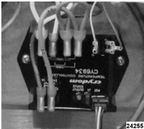
Fig. 8
WATER LEVEL CONTROL

WARNING
Disconnect the electrical power to the machine and follow lockout / tagout procedures.
- Remove CONTROL BOX COVER.
- Disconnect lead wires from the water level control.
- Remove screws securing the water level control to panel.
- Reverse procedure to install and check for proper operation.

natural_image
Close-up of an electronic circuit board with wires and components, no visible text or symbolsFig. 9
MAIN TRANSFORMER

WARNING
Disconnect the electrical power to the machine and follow lockout / tagout procedures.
- Remove CONTROL BOX COVER.
- Disconnect lead wires from the transformer.
- Remove screws securing the transformer to panel.
- Reverse procedure to install and check for proper operation.

Fig. 10
HEATING ELEMENT

WARNING
Disconnect the electrical power to the machine and follow lockout / tagout procedures.
TILTING KETTLE
- Open pressure relief valve until reservoir jacket is completely vented.
- Remove BOTTOM COVER.
- Remove wire from water level probe (LLCO).
- Place a large container under the kettle. Remove water level probe (LLCO) and open the fill valve (40 & 60 gallon kettles) or remove pipe plug from fill elbow (20 gallon kettles) to vent the jacket and drain liquid from kettle.

Fig. 11
NOTE: If liquid drained from kettle is still clean, save for reuse.
5. Remove heater access cover.

Fig. 12
6. Note lead wire locations and disconnect wires from heating element.
7. Remove mounting bolts securing heating element to kettle.
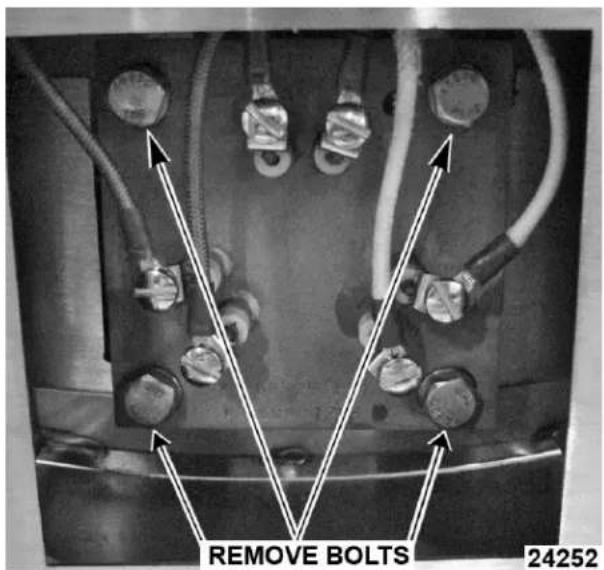
Fig. 13
8. Remove heating element from kettle.
9. Reverse procedure to install. Use a new heating element seal whenever installing heating element. Torque mounting nuts to 40 ft-lbs and tighten in an alternating pattern.
10. Refill jacket with fluid. See FILLING THE RESERVOIR JACKET.
11. Remove air from reservoir jacket as outlined under VENTING.
12. Check for proper operation and leaks around heating element.
STATIONARY KETTLE
- Open pressure relief valve until reservoir jacket is completely vented.
- Remove BOTTOM COVER.
- Remove wire from Water Level Probe (LLCO).
- Place a large container under the kettle. Remove water level probe (LLCO) and open the fill valve (40 & 60 gallon kettles) or remove pipe plug from fill elbow (20 gallon kettles) to vent the jacket and drain liquid from kettle.

Fig. 14
NOTE: If liquid drained from kettle is still clean, save for reuse.
- Remove CONTROL BOX COVER.
- Note lead wire locations and disconnect wires from heating element.
- Remove mounting nuts securing heating element to kettle.

Fig. 15
- Remove heating element from kettle.
-
Reverse procedure to install. Use a new heating element seal whenever installing heating element. Torque mounting bolts to 40 ft-lbs and tighten in an alternating pattern.
-
Refill jacket with fluid. See FILLING THE RESERVOIR JACKET.
- Remove air from reservoir jacket as outlined under VENTING.
NOTE: Step 12 is applicable for flange change on production units starting with serial number break 46-3030197.
- Torque all flange bolts to 38 Ft/Lbs. in 3 passes as shown in Fig. 16.
NOTICE
It is recommended to heat kettle up to boil for one hour. After kettle cools down to -20 to -30 HG and recheck torque to verify 38 Ft/Lbs.
A. 1st pass 13 ft/lbs.
B. 2nd pass 26 ft/lbs.
C. 3rd pass 38 ft/lbs.

Fig. 16
- Check for proper operation and leaks around heating element.
WATER LEVEL PROBE (LLCO)

WARNING
Disconnect the electrical power to the machine and follow lockout / tagout procedures.
-
Open pressure relief valve until reservoir jacket is completely vented.
-
Remove BOTTOM COVER.
- Disconnect lead wires from the water level probe.

Fig. 17
- Place a large container under kettle to catch liquid that drains from kettle.
NOTE: If liquid drained from kettle is still clean, save for reuse.
- Remove component from bottom of kettle.
- Reverse procedure to install.
NOTE: Clean threads and apply pipe thread sealant when replacing water level probe.
- Refill jacket with fluid. See FILLING THE RESERVOIR JACKET.
- Remove air from reservoir jacket as outlined under VENTING.
- Check for proper operation.
TEMPERATURE SENSOR

WARNING
Disconnect the electrical power to the machine and follow lockout / tagout procedures.
- Open pressure relief valve until reservoir jacket is completely vented.
- Remove BOTTOM COVER.
- Place a large container under the kettle to catch liquid that drains from kettle.
NOTE: If liquid drained from kettle is still clean, save for reuse.
4. Remove component from bottom of kettle.
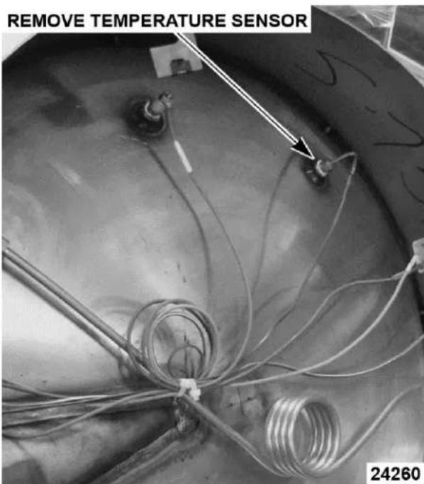
Fig. 18
- Reverse procedure to install.
NOTE: Clean threads and apply pipe thread sealant when replacing temperature sensor. - Refill jacket with fluid. See FILLING THE RESERVOIR JACKET.
- Remove air from reservoir jacket as outlined under VENTING.
- Check for proper operation.
PRESSURE SWITCH

WARNING
Disconnect the electrical power to the machine and follow lockout / tagout procedures.
- Open pressure relief valve until reservoir jacket is completely vented.
- Remove BOTTOM COVER.
- Disconnect lead wires from the pressure switch.
- Place a large container under the kettle to catch liquid that drains from kettle.
NOTE: If liquid drained from kettle is still clean, save for reuse.
- Disconnect compression fitting from elbow near the pressure switch.
- Remove top nut on brass fitting to remove pressure switch from mounting bracket.
- Remove component from bottom of kettle.

Fig. 19
- Reverse procedure to install.
NOTE: Pressure switch setting is fixed and should not be adjusted. Clean threads and apply pipe thread sealant when replacing pressure switch. - Refill jacket with fluid. See FILLING THE RESERVOIR JACKET.
- Remove air from reservoir jacket as outlined under VENTING.
- Check for proper operation.
POTENTIOMETER
WARNING
Disconnect the electrical power to the machine and follow lockout / tagout procedures.
- Remove CONTROL BOX COVER.
-
Disconnect potentiometer wire from temperature control.
-
Pull temperature dial from potentiometer shaft and remove seal nut.

Fig. 20
- Remove potentiometer from control panel.
- Reverse procedure to install and check for proper operation.
NOTE: When installing, ensure potentiometer alignment tab is seated in positioning bracket.

Fig. 21
SWITCH ASSEMBLY

WARNING
Disconnect the electrical power to the machine and follow lockout / tagout procedures.
-
Remove CONTROL BOX COVER.
-
Note lead wire location and disconnect wires from switch.
- Press down on tabs to free switch from housing.

Fig. 22
- Reverse procedure to install.
GEARBOX (TILT MODELS ONLY)
WARNING
Disconnect the electrical power to the machine and follow lockout / tagout procedures.
- Place a pallet jack under the kettle of the unit.
NOTE: Place pallet jack under kettle and not under the tubular frame.
NOTE: Place 2x4 or 4x4s on the pallet jack if needed to reach the bottom of the kettle. - Remove CONTROL BOX COVER.
- Note location of wiring and remove element, pressure switch wires and unplug the sensor plug.
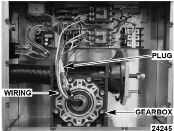
Fig. 23
- Remove the four bolts holding the gearbox to the component box.
- Lift the kettle just high enough to slide the gearbox off of the shaft and clear the component box lip.
NOTE: Be careful not to damage the wiring as you remove gearbox from shaft.
- Remove the positive stop plate assembly from the old gearbox and install it on the new one.

Fig. 24
- Install new gearbox in kettle.
- Lower the gearbox until it touches component box housing.
NOTE: Only lower the gearbox enough to align the holes and bolt the gearbox down.
- Lower the kettle and remove pallet jack.
- Connect the wiring.
- Check operation of kettle.
TILT BEARING

WARNING
Disconnect the electrical power to the machine and follow lockout / tagout procedures.
- Place pallet jack under kettle.
NOTE: Make sure pallet jack is under kettle and not under the tubular frame.
NOTE: Place 2x4 or 4x4s on the pallet jack if needed to obtain the proper height.
- Loosen set screws on bearing assembly.
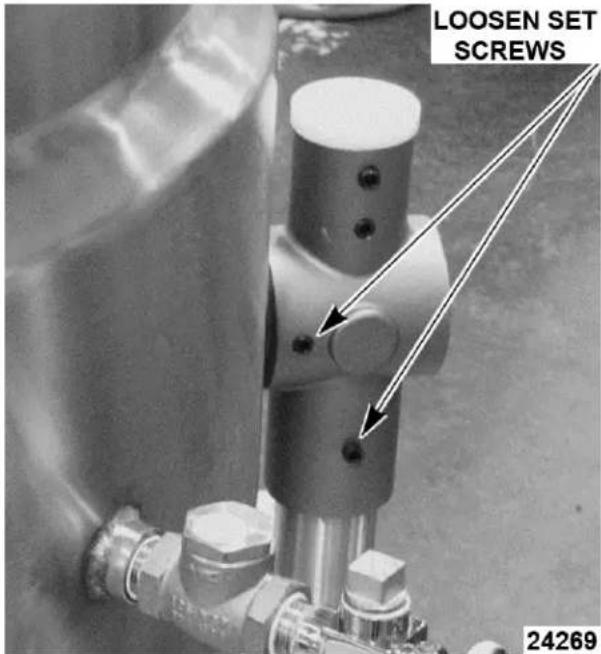
Fig. 25
- Lift kettle high enough to pull bearing assembly off of stand.
- Slide bearing assembly off of kettle shaft.
- Reverse procedure to install new bearing assembly.
SERVICE PROCEDURES AND ADJUSTMENTS
WARNING
Certain procedures in this section require electrical test or measurements while power is applied to the machine. Exercise extreme caution at all times. If test points are not easily accessible, disconnect power and follow lockout / tagout procedures, attach test equipment and reapply power to the test.
- Place kettle in full upright position. (tilt kettles only)
- Set temperature dial to lowest setting. Kettle must be below 110^ F before verifying the potentiometer output to the controller is good over the full range of temperature dial travel.
- Access TEMPERATURE CONTROLLER.
- Check all lead wires for secure connections to the controller terminals. Wiring harness lead wires must be connected to T1-T2 and T3-T4 for proper input to controller.
- Re-connect power to the machine.
- Turn power switch on.
- Verify temperature controller is receiving 120VAC at terminals T1-T3 and T2-T4 and machine is properly grounded.
- Slowly turn temperature dial to the highest setting and monitor heat light over the full range of travel.
A. Verify heat light (amber) comes on and heating element is energized.
B. If heat light does not remain on or flashes momentarily as temperature setting is slowly increased, verify condition of potentiometer as outlined under POTENTIOMETER TEST.
NOTE: Temperature controller will de-energize internal relay and turn off the output status LED if the circuitry detects an open thermocouple. LED will begin to flash 3 times, pause, then repeat the flash sequence to indicate the open thermocouple condition.
C. If heat light and heating element do not turn on.
1) Verify condition of thermocouple as outlined under THERMOCOUPLE TEST.
2) Verify output from terminal T8 on controller as outlined in the steps below.
- Disconnect lead wire from terminal T7 on the controller.
A. Verify 120VAC between lead wire from T7 and X1 on the output of main transformer. If correct, re-connect lead wire to terminal T7 and continue with procedure.
B. If incorrect, check pressure switch (1PS) and water level controller (WLC LLCO).
- Verify 120VAC between T8 and X1 on the output of main transformer. If correct, output from controller is functioning properly.
A. If incorrect, install a replacement temperature controller and check for proper operation.
POTENTIOMETER TEST
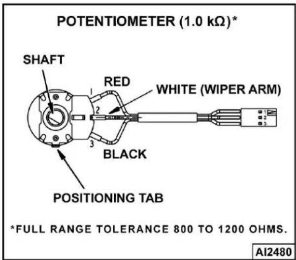
Fig. 27
- Remove POTENTIOMETER.
- Turn potentiometer shaft fully counterclockwise to the lowest setting.
- Set VOM to measure resistance.
- Connect meter leads to the white and black lead wires on potentiometer terminals.
A. Resistance should measure approximately zero ohms.
- Slowly turn potentiometer shaft clockwise over the full range of travel and monitor resistance change on the meter.
A. Resistance should measure 800 to 1200 ohms with shaft turned fully clockwise.
B. If the resistance value increased smoothly without sudden drops or spikes and the full travel resistance value is within tolerance then potentiometer is functioning properly.
C. If the resistance value did not increase smoothly but had drops or spikes over the full travel range then potentiometer is not functioning properly. Install a replacement potentiometer and check for proper operation.
THERMOCOUPLE TEST

Fig. 28
- Access TEMPERATURE CONTROLLER.
- Remove thermocouple lead wires from temperature controller.
- Check thermocouple for a measurable resistance (approximately 5 to 10 ohms at room temperature). If meter reads an overload (OL) condition (open), or zero ohms (short) replace the thermocouple and check temperature controller for proper operation.
VENTING
NOTE: This procedure outlines venting the reservoir jacket to remove air for proper heat transfer to the kettle contents.

Fig. 29
- With the kettle at room temperature, verify pressure gauge is in the vacuum zone and reading 25 to 30 in. Hg.
A. If vacuum is below minimum listed, air must be removed from reservoir jacket. Continue with procedure to vent as necessary.
- Place kettle in full upright position.
- Turn power switch on.
- Set temperature dial to highest setting. Allow kettle to heat until the heat indicator light turns off.
- Open pressure relief valve for approximately 10 seconds.
- Turn power switch off and allow kettle to cool (room temperature).
| MODEL VOLTAGE KW PER ELEMENT | CURRENT PER ELEMENT | RESISTANCE PER ELEMENT (OHMS) | ||
| K20EL/K20ELT | 208 4 19.2 10.8 | |||
| 240 16 22.2 10.8 | ||||
| 480 12 14.4 19.2 | ||||
| K40EL/K40ELT | 208 6 28.8 7.2 | |||
| 240 6 25.0 9.6 | ||||
| 480 6 21.7 12.8 | ||||
| K60EL/K60ELT | 208 8 38.5 5.4 | |||
| 240 8 33.3 7.2 | ||||
| 480 8 28.9 6.0 | ||||
- Verify pressure gauge reading is within the correct vacuum range.
A. If reading is below minimum listed or will not maintain proper vacuum, check all threaded fittings extending from the kettle couplings (right and rear) for leaks and tightness.
1) Check pressure relief valve for leaks from poor valve seating or built up debris. Manually operate the valve several times to reseat. Repeat venting procedure.
2) If pressure relief valve is malfunctioning, install a replacement and check for proper operation.
HEATING ELEMENT
- Access HEATING ELEMENT.
- Measure voltage at heating element terminals and verify it against the data plate voltage.
A. If voltage is incorrect, find the source of the problem.
- If voltage is correct, check current draw (amps) through the heating element lead wires. If current draw is correct then heating element is ok. See table below for proper values.
NOTE: Checking current draw is the preferred method over a resistance check when an amp clamp meter is available.
A. If current draw is not correct then, replace heating element.
4. Check for proper operation.
| MODEL VOLTAGE KW PER ELEMENT | CURRENT PER ELEMENT | RESISTANCE PER ELEMENT (OHMS) | |
| NOTE: Values in table are nominal. Tolerance is ±10 %. | |||
KETTLE TILT ADJUSTMENT (TILT MODELS ONLY)
NOTE: Perform this procedure whenever the kettle is not returning to a horizontal position when upright, or when kettle is not tilting past 90^ to empty contents.
- With kettle fully upright, the top of kettle should be horizontal when viewed from either side.
- Turn crank handle clockwise to tilt the kettle until it stops. Kettle should be tilted past 90^ to allow contents to drain.
- If adjustment is necessary, continue with procedure.
- Remove CONTROL BOX COVER.
- Return kettle to fully upright position.
A. The inner jam nut should be in solid contact with positive stop traveller.
B. To adjust upright position (horizontal):
1) Loosen outer jam nut 2 to 3 turns counterclockwise and turn the inner jam nut in the same direction and amount.
2) Turn crank handle to position the top of kettle horizontally.
3) Turn inner jam nut clockwise until it stops against the positive stop traveller. Tighten outer jam nut to secure the stop position.
C. Turn crank handle to verify operation. Repeat adjustment as necessary.

Kettle Fully Upright - Traveller Contacts Inner Jam Nut
- Fully tilt the kettle until crank handle stops.
A. Verify positive stop traveller is in solid contact with stop plate.
B. To adjust fully tilted position:
1) Remove shoulder screw from stop plate.
2) Remove tilt switch bracket from stop plate.

Kettle Fully Tilted - Traveller Contacts Stop Plate
3) Turn crank handle clockwise to tilt the kettle and empty its contents. Kettle should be tilted approximately 95^ to 100^ .
4) Turn positive stop traveller on the positive stop shaft (threaded) until it contacts the stop plate.
5) Adjust position of positive stop traveller as needed to align the shoulder screw mounting hole to the threaded hole in stop plate. Install shoulder screw.
6) Turn crank handle to verify operation. Repeat adjustment as necessary.
7) Install tilt switch bracket.
- Install control panel cover.
FILLING THE RESERVOIR JACKET
NOTE: The reservoir water level must be maintained high enough to submerge the heating element. If low water light comes on during use, the level may be below water level probe (LLCO) and must be replenished before heating can continue. The low water light will come on when kettle is tilted (tilt models only).
NOTICE
When filling reservoir jacket, use only distilled water and heat transfer fluid. The ratio is 2:1, 2 parts distilled water, 1 part Heat Transfer Fluid.
Partial Refill
- Place kettle in full upright position. (tilt kettle only)
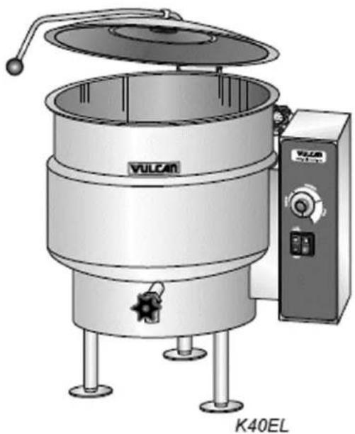
natural_image
Illustration of a VULCAN K40EL mixing machine with control panel and side legs (no text or symbols on the device itself)Fig. 32
-
Turn power switch on. If low water light is on, continue with procedure.
-
Set temperature dial to lowest setting.
WARNING
Pressure Relief Valve Exhaust. DO NOT connect to building water, gas, or steam supply. DO NOT block or restrict.
WARNING
Hot steam. The kettle and its parts are hot. Use care when operating, cleaning or servicing the kettle.
- Open pressure relief valve until reservoir jacket is completely vented.
- Remove 1/2" pipe plug from the reservoir jacket fill elbow at back of kettle. Open fill valve. (40 and 60 gallon kettles only)
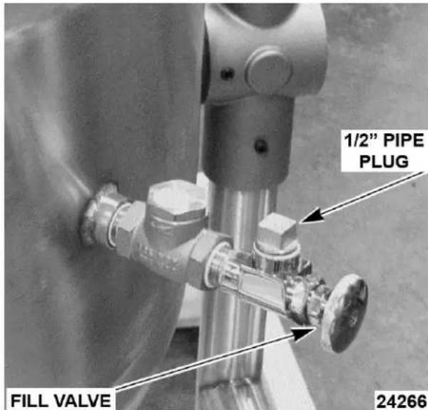
K40EL/K40ELT and K60EL/K60ELT

K20ELT, K20ELT
A. Insert funnel into the opening and slowly add a mixture of water and heat transfer fluid until low water light turns off (LLCO probe is satisfied).
B. Set the thermostat and power switch to OFF position.
C. Continue adding a mixture of water and heat transfer fluid to bring fluid to the proper operating level per the amount listed in the RESERVOIR JACKET VOLUME table below.
NOTE: Heat Transfer Fluid: Thermodyne 90395 GLYCOL, Heat Transfer Fluid, 1 gallon, available at Parts Town or DOWFROST™ Propylene Glycol at ChemWorld.
-
Clean pipe plug threads and apply thread sealant. Install pipe plug and tighten to prevent leaks. Close fill valve. (40 and 60 gallon kettles only)
-
Turn power switch on and verify low water light is off. If low water light is on, there may be a problem with the water level control circuit. See TROUBLESHOOTING.
-
Remove air from reservoir jacket as outlined under VENTING.
- Check kettle for proper operation.
| Model Water | Heat Transfer FluidFood GradeAntifreeze | Total | Low LevelLight OFF | Light OFFTo Fill | |
| K20EL / K20ELT | 8 4 12 9 3 | ||||
| K40EL / K40ELT | 12 6 18 10 8 | ||||
| K60EL / K60ELT | 14 7 21 12 9 | ||||
Complete Draining and Refill
NOTE: Appearance of fluid will no longer be clear after usage in kettle.

WARNING
Disconnect the electrical power to the machine and follow lockout / tagout procedures.
WARNING
Pressure Relief Valve Exhaust. DO NOT connect to building water, gas, or steam supply. DO NOT block or restrict.
WARNING
Hot steam. The kettle and its parts are hot. Use care when operating, cleaning or servicing the kettle.
- Disconnect power supply and set temperature dial to lowest setting.
- Open pressure relief valve until reservoir jacket is completely vented.
- Remove BOTTOM COVER.
- Place a large container under kettle to catch liquid.
- Remove WATER LEVEL PROBE (LLCO).
- Remove 1/2" pipe plug from reservoir jacket fill elbow (rear of kettle) to facilitate draining and provide opening for re-fill. (Open fill valve on 40 and 60 gallon kettles)
NOTE: Clean threads and apply sealant before reinstalling pipe fittings.
-
Re-install water level probe.
-
To Refill.
A. Remove pressure gauge to allow reservoir jacket to vent during fill procedure.
B. Insert funnel into the reservoir jacket fill elbow. Slowly fill the jacket according to the volumes listed in the RESERVOIR JACKET VOLUME table below.
A. Remove pressure gauge to allow reservoir jacket to vent during fill procedure. B. Insert funnel into the reservoir jacket fill elbow. Slowly fill the jacket according to the volumes listed in the RESERVOIR JACKET VOLUME table below.
-
Install pipe plug and pressure gauge. Tighten to prevent leaks.
-
Reapply power and turn power switch on and verify low water light is off. If low water light is on, there may be a problem with the water level control circuit. See troubleshooting.
-
Remove air from reservoir jacket as outlined under VENTING.
-
Install covers.
-
Check kettle for proper operation and leaks.
| RESERVOIR JACKET VOLUME | |||
| Model Total Fluid Volume (Qt) Water (Qt) Heat Transfer Fluid (Qt) | |||
| K20EL/K20ELT 12.0 8.0 | 4.0 | ||
| K40EL/K40ELT 18.0 12.0 | 6.0 | ||
| K60EL/K60ELT 21.0 14.0 | 7.0 | ||
| COMPONENT FUNCTION | |
| Water Level Control (WLC LLCO) .... | Low water level control. Monitors condition of the WLC LLCO water level probe. Protects kettle from a low water condition in the reservoir jacket and removes power from heating circuit when kettle is tilted. |
| Probe, Water Level (LLCO) .... | Low Level Cut-Off (LLCO) probe connected to WLC (LLCO). Controls power to heating circuit. |
| Contactor (1CON) Limiting .... | Connects one side of heating element to power. Energized whenever WLC (LLCO) coil is energized (WLC LLCO contacts closed). |
| Contactor (2CON) Regulating .... | Connects heating element to power. On constantly when temperature controller is calling for heat (temperature controller contacts closed). |
| Element, Heating .... | Heats reservoir jacket fluid. The heat in the fluid is then transferred to kettle. |
| Fuse, (1FU & 2FU) .... | Slow blow 3A fuse. Located on primary side of main transformer (1T). Protects control circuitry from over-currents. |
| Switch (1PAS), Pressure .... | Pressure cut-out protection for the reservoir jacket. Range is between 38 to 42 PSI. Removes power from control circuit if pressure in the jacket rises above switch setting. |
| Transformer (1T), Main .... | Step down transformer from line voltage to 120VAC control circuit voltage. |
| Switch (1S), Power ... | Controls 120VAC to kettle control circuit |
| Temperature Controller .... | Cycles power to regulating contactor (2CON) to maintain the set point temperature. An external set point potentiometer is used for temperature adjustments. |
| Lamp (1LT), Power ... | Amber (AM) colored lamp. On when power switch is on. |
| Lamp (2LT), Low Water .... | Red (RD) colored lamp. On when water level in the reservoir jacket drops below water level (LLCO) probe or when kettle is tilted (tilting models only). |
| Lamp (3LT), Heat .... | Amber (AM) colored lamp. On when temperature controller is calling for heat. |
COMPONENT LOCATION


24271
TILTING KETTLE COMPONENTS
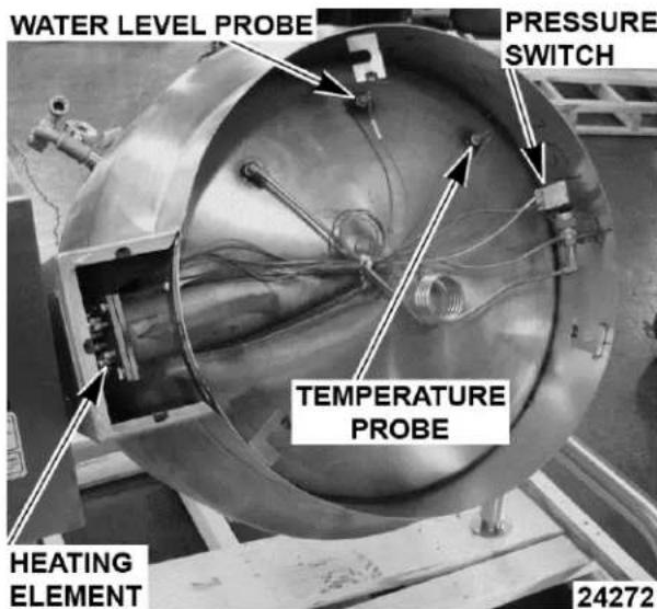
STATIONARY AND TILTING KETTLE BOTTOM COMPONENTS
WATER LEVEL CONTROL (WLC LLCO)
The water level control provides low level cut-off protection to shut off the heat source in case the fluid
level in the kettle reservoir jacket drops below the WLC LLCO probe. A single low level cut-off probe (LLCO) is connected to the control.
The water level control has input voltage of 120VAC across terminals L1 and L2 which powers the primary side of the transformer on the board. One side of the
transformer secondary is powered through a series path to chassis ground. The other side of the transformer secondary (12VAC) is connected to the LLCO coil and the LLCO LED. The grounded potential is carried through the water in the reservoir jacket to the LLCO probe. When the kettle is in the full upright position and the reservoir jacket fluid is at the proper level, the fluid is in constant contact with the LLCO probe and the circuit is completed.
When the power switch is turned ON, power is supplied to the water level control. With the kettle in the full upright position and the fluid level in the reservoir jacket in contact with the LLCO probe, the LLCO relay coil is energized. The LLCO relay contacts WLC LLCO-NC open, WLC LLCO-NO close and the LLCO LED turns on. When the kettle is tilted to empty the contents, the fluid is no longer in contact with the LLCO probe and the circuit is open. The LLCO relay coil is de-energized and LLCO LED turns off.

Fig. 38

Fig. 39
A. Kettle connected to correct voltage supply and is properly grounded.
1) 120VAC potential across X2 and X1 on secondary of main transformer.
B. Power switch and light (1LT) (amber) are off.
C. Low water light (2LT) (red) is off.
D. Pressure switch (1PAS) contacts closed.
E. Temperature dial at lowest setting (potentiometer fully CCW).
1) Internal relay contacts N.O. are open.
F. Kettle at room temperature and in the full upright position.
- Power switch turned ON.
A. Power light (1LT) (amber) comes on.
B. Power from secondary of main transformer to control circuit thru pressure switch (1PAS) N.C. contacts.
- Water level control (WLC) energized.
A. WLC LLCO probe satisfied (fluid in kettle reservoir jacket at proper level).
1) LLCO LED comes on.
B. WLC LLCO N.C. contacts open. Low water light (2LT) (red) remains off.
C. WLC LLCO N.O. contacts close.
1) Limiting contactor (1CON) energized (power to one side of heating elements).
2) Power to temperature controller.
- Set the temperature dial to call for heat (warm/simmer/boil).
A. 120VAC output from T8 on temperature controller.
1) Heat light (3LT) (amber) comes on.
2) Regulating contactor (2CON)
energized and heating elements are powered.
- Kettle reaches set point temperature.
A. Voltage output removed from T8 on temperature controller.
1) Heat light (3LT) (amber) goes out.
2) Regulating contactor (2CON) de-energized and powered is removed from heating elements.
- Kettle heat cycles with the temperature controller.
- Kettle tilted to empty contents.
A. WLC LLCO probe no longer satisfied (fluid in kettle reservoir jacket not in contact with probe). Water level control (WLC) LLCO relay de-energized.
1) LLCO LED turns off.
B. WLC (LLCO) N.C. contacts close and low water light (2LT) (red) comes on.
C. WLC (LLCO) N.O. contacts open and power is removed from heating circuit.
- Kettle returned to upright position. Water level control (WLC) circuit returns to normal operation and heating cycle resumes. Kettle heating will continue to cycle with the temperature controller until the temperature dial is turned fully CCW or power switch is turned OFF.
SCHEMATIC DIAGRAM

flowchart
graph TD
    A["Power Switch (1S)"] --> B["FUSE (1FU)"]
    B --> C["MAIN TRANSFORMER (1T)*"]
    C --> D["X2"]
    D --> E["X1"]
    E --> F["POWER (1LT)"]
    F --> G["AM"]
    G --> H["LOW WATER (2LT)"]
    H --> I["RD"]
    I --> J["REGULATING CONTACTOR (2CON)"]
    J --> K["HEAT (3LT)"]
    K --> L["AM"]
    L --> M["POWER SWITCH (1S)"]
    M --> N["OFF"]
    N --> O["PRESSURE SWITCH (1PAS)"]
    O --> P["Pressure Switch (1S)"]
    P --> Q["WLC (LLCO)"]
    Q --> R["LIT"]
    R --> S["LOW WATER (2LT)"]
    S --> T["LOW WATER (2LT)"]
    T --> U["LIT"]
    U --> V["LOW WATER (2LT)"]
    V --> W["LIT"]
    W --> X["LIT"]
    X --> Y["LIT"]
    Y --> Z["LIT"]
    Z --> AA["LIT"]
    AA --> AB["LIT"]
    AB --> AC["LIT"]
    AC --> AD["LIT"]
    AD --> AE["LIT"]
    AE --> AF["LIT"]
    AF --> AG["LIT"]
    AG --> AH["LIT"]
    AH --> AI["LIT"]
    AI --> AJ["LIT"]
    AJ --> AK["LIT"]
    AK --> AL["LIT"]
    AL --> AM["LIT"]
    AM --> AN["LIT"]
    AN --> AO["LIT"]
    AO --> AP["LIT"]
    AP --> AQ["LIT"]
    AQ --> AR["LIT"]
    AR --> AS["LIT"]
    AS --> AT["LIT"]
    AT --> AU["LIT"]
    AU --> AV["LIT"]
    AV --> AW["LIT"]
    AW --> AX["LIT"]
    AX --> AY["LIT"]
    AY --> AZ["LIT"]
    AZ --> BA["LIT"]
    BA --> BB["LIT"]
    BB --> BC["LIT"]
    BC --> BD["LIT"]
    BD --> BE["LIT"]
    BE --> BF["LIT"]
    BF --> BG["LIT"]
    BG --> BH["LIT"]
    BH --> BI["LIT"]
    BI --> BJ["LIT"]
    BJ --> BK["LIT"]
    BK --> BL["LIT"]
    BL --> BM["LIT"]
    BM --> BN["LIT"]
    BN --> BO["LIT"]
    BO --> BP["LIT"]
    BP --> BQ["LIT"]
    BQ --> BR["LIT"]
    BR --> BS["LIT"]
    BS --> BT["LIT"]
    BT --> BU["LIT"]
    BU --> BV["LIT"]
    BV --> BW["LIT"]
    BW --> BX["LIT"]
    BX --> BY["LIT"]
    BY --> BZ["LIT"]
Fig. 40
WIRING DIAGRAMS
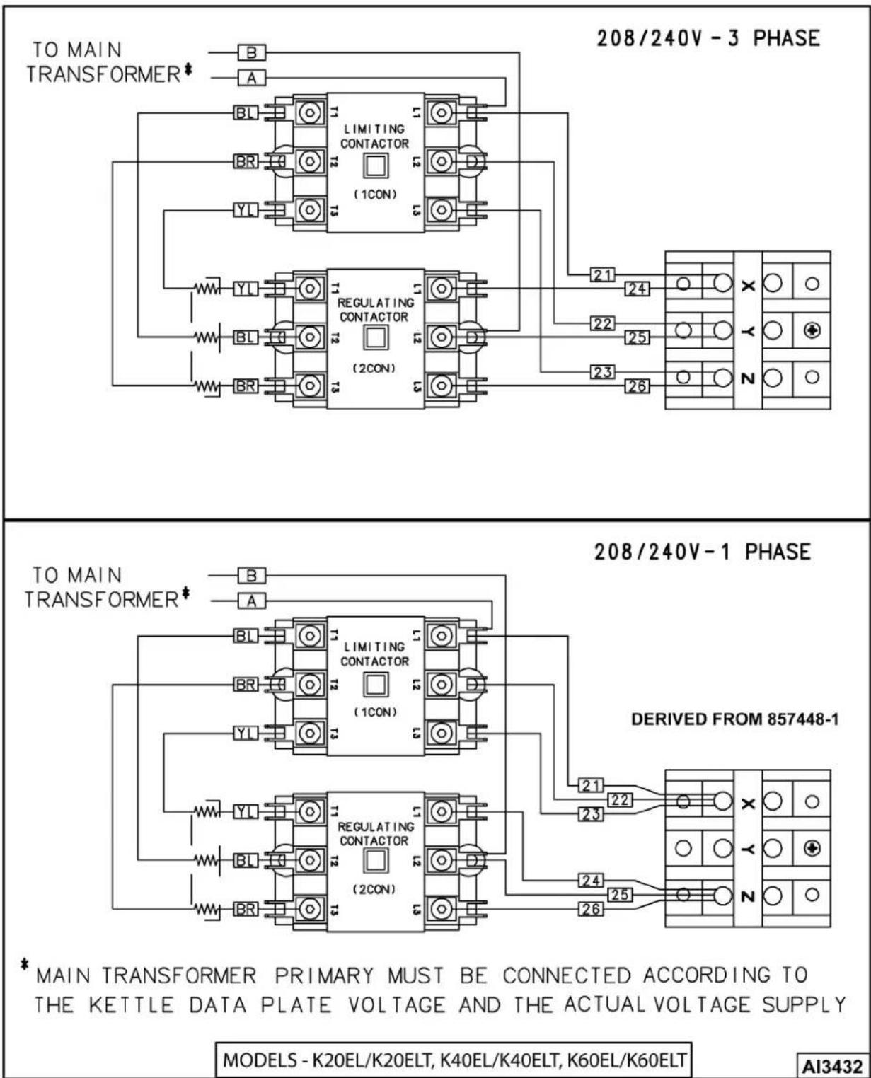
Fig. 41

Fig. 42
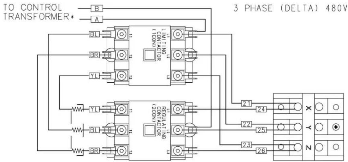
*PRIMARY TAPS OF CONTROL TRANSFORMER MUST BE CONNECTED ACCORDING TO THE APPLIANCE DATA PLATE VOLTAGE MARKING AND ACTUAL CONNECTED SUPPLY

Models - K20EL/K20ELT, K40EL/K40ELT, K60EL/K60ELT AI3434
Fig. 43
TROUBLESHOOTING
TROUBLESHOOTING
| SYMPTOM POSSIBLE CAUSES | |
| Kettle does not heat, power light is lit, heat light is lit, low water light is not lit. | 1. Limiting contactor (1CON) malfunction.2. Regulating contactor (2CON) malfunction.3. Heating element malfunction. |
| Kettle does not heat, power light is lit, low water light is lit, heat light is not lit. | 1. Fluid level in reservoir jacket below water level probe (LLCO).2. Water level probe (LLCO) wiring connection malfunction; or probe coated (not sensing fluid); or probe malfunction.3. Water level control malfunction. |
| Kettle does not heat, power light is lit, low water light is not lit, heat light is not lit. | 1. Pressure switch (1PAS) malfunction.2. Temperature sensor malfunction; potentiometer malfunction or temperature controller malfunction.3. Interconnecting wiring malfunction. |
| Kettle does not heat, power light is not lit. | 1. Main circuit breaker off; or control circuit fuse F1 or F2 open.2. Supply voltage incorrect.3. Main transformer (1T) malfunction.4. Power switch off or malfunction.5. Interconnecting wiring malfunction. |
| Kettle heats up slow or will not boil product. | 1. No vacuum in reservoir jacket when kettle is cold.2. Supply voltage incorrect.3. Heating element malfunction.4. Temperature sensor malfunction; or potentiometer malfunction; or temperature controller malfunction. |
- Electric Stationary and Tilting Kettles
- - NOTICE -
- TABLE OF CONTENTS
- December 2020
- July 2018
- October 2017
- GENERAL
- INTRODUCTION
- Stationary and Tilting Kettles
- TOOLS
- Standard
- Special
- SPECIFICATIONS
- Reservoir Jacket Fluid
- OPERATION, CLEANING AND MAINTAINENCE
- REMOVAL AND REPLACEMENT OF PARTS
- CONTROL BOX COVER
- WARNING
- BOTTOM COVER
- COMPONENT PANELS
- HEATING CONTACTORS
- WATER LEVEL CONTROL
- MAIN TRANSFORMER
- HEATING ELEMENT
- TILTING KETTLE
- STATIONARY KETTLE
- NOTICE
- WATER LEVEL PROBE (LLCO)
- TEMPERATURE SENSOR
- PRESSURE SWITCH
- POTENTIOMETER
- SWITCH ASSEMBLY
- GEARBOX (TILT MODELS ONLY)
- TILT BEARING
- SERVICE PROCEDURES AND ADJUSTMENTS
- POTENTIOMETER TEST
- THERMOCOUPLE TEST
- VENTING
- KETTLE TILT ADJUSTMENT (TILT MODELS ONLY)
- FILLING THE RESERVOIR JACKET
- Partial Refill
- Complete Draining and Refill
- COMPONENT LOCATION
- WATER LEVEL CONTROL (WLC LLCO)
- TROUBLESHOOTING
Brand : Vulcan
Model : K20ELT
Category : Kettle