
UTS6H - Interrupteur de transfert électrique APC - Free user manual and instructions
Find the device manual for free UTS6H APC in PDF.


| Product Type | Universal Transfer Switch (UTS) |
| Brand | APC by Schneider Electric |
| Model | UTS6H |
| Input Voltage (Utility) | 120 V AC single phase |
| Rated Current (Generator Input) | 30 A |
| Number of Circuits | 6 (all 120 V AC) |
| Frequency Range | 47 Hz to 63 Hz |
| Backup Power Sources | Generator (Backup1) and UPS (Backup2) |
| Generator Start Mode | Manual or automatic (with optional kit) |
| Display | LCD, 2 lines x 20 characters |
| Dimensions (H x W x D) | 39.4 x 49.8 x 8.3 cm (15.5 x 19.6 x 3.3 in) |
| Weight | 21.5 lbs (9.75 kg) |
| Operating Temperature | -25°C to 40°C (-13°F to 104°F) |
| Mounting | Wall mount (surface or flush) |
| Circuit Protection | UL-Listed Class CC fuses (15 A or 20 A) |
| Convenience Outlet | NEMA 5-15, 120 V, 15 A |
| Key Features | Adaptive Load Management (ALM), Automatic Load Transfer, Voltage Sensitivity, Security Mode, Bypass Mode |
| Warranty | 2 years limited |
| Regulatory Compliance | FCC Class B |
| Included Accessories | Power cord, fuses, wire nuts, ring lugs, strain relief clamp, mounting hardware |
Frequently Asked Questions - UTS6H APC
User questions about UTS6H APC
0 question about this device. Answer the ones you know or ask your own.
Ask a new question about this device
Download the instructions for your Interrupteur de transfert électrique in PDF format for free! Find your manual UTS6H - APC and take your electronic device back in hand. On this page are published all the documents necessary for the use of your device. UTS6H by APC.
USER MANUAL UTS6H APC
Site Preparation and Installation Guide
Universal Transfer Switch
UTS6
UTS6H
UTS6BI
UTS10BI
UTS10BI

About this product
The APC ^® by Schneider Electric Universal Transfer Switch (UTS) is a fully automatic transfer switch for use in optional standby systems in homes or small businesses. This unit provides safe, convenient power for up to ten circuits in the home or office. Power is derived from one or two independent backup sources. Backup sources being a generator, an uninterruptible power supply (UPS), a solar inverter, or another alternative energy source.
When connected to home appliances, computers, or entertainment equipment the backup power sources provide power during utility power outages. When a UPS is used in the configuration, connected equipment (load), can be protected from utility brownouts, sags, surges, and power outages. The UPS provides continuous power from the internal battery until utility power returns to safe levels or the battery is fully discharged.
The models supported by this manual vary in appearance and have some variation in function.
Individual model functionality will be addressed in this manual.

Protect your investment
Fill out the Warranty Registration Card found in the documentation package, or register your purchase online at www.apc.com:
- This will guarantee that the owner receive all of the information and special offers qualified for as the owner of this product.
- This will confirm the owners right to maximum protection under the Warranty terms and conditions.
- This will confirm yourself as the owner of the product in the event of fire, theft or loss.
Recommended Tools Recommended Cables
• Phillips screw driver
- standard screw driver
- wire cutter/stripper for 10-12 gauge wire
- utility knife
- insulated pliers
• Robertson #3 square head bit crimping tool
UTS6/6BI/10BI models
UF 10-3 power cable or equivalent of sufficient length to connect the UTS to a fixed generator or a remote L14 connector.
A larger gauge cable may be needed depending on the rated current of the connected generator.
UTS6H models
UF 10-2 power cable or equivalent of sufficient length to connect the UTS to a fixed generator or a remote L5 connector.
Inventory
Inspect the UTS upon receipt. Notify the carrier and dealer if there is damage.
The packaging is recyclable; save it for reuse or dispose of it properly.
Check the package contents:
| All Units | Additional contents for UTS6/UTS6H/UTS6BI | Additional contents for UTS10BI |
| UTS Hardware: Hardware: | ||
| UTS-to-UPS power cord • male-to-male .25 inch bypass FastOns (six) | • male-to-male .25 inch bypass FastOns (ten) | |
| Site Preparation and Installation Guide | • .50 in x .27 in plastic ID spacers (four) | • .50 in x .27 in plastic ID spacers (four) |
| Quick Install Guide • 20 A, 600 Vac class CC fuse (one) • 20 A, 600 Vac class CC fuse (one) | ||
| Operation Manual • 2 x 10 AWG solid wire nuts (six) | • 2 x 10 AWG solid wire nuts (ten) | |
| Warranty Registration card | ||
| Flat head screws (three) | ||
| Ring lug #8 AWG 10-12 (one) | ||
| Ring lug #8 AWG 14-16 (one) | ||
| Locknut with strain relief cable clamp (one) | ||
Safety and Regulatory Information - save this information
Read the Site Preparation and Installation Guide and the Operation Manual before installing and operating the UTS.
Read, understand, and follow the Safety Precautions in this manual.
Safety Precautions
- Adhere to all national and local electrical codes when installing, configuring and operating the UTS.
• Installation of the UTS must be performed by a licensed electrician. - Prior to installing the UTS have a licensed electrician check that the wiring in the home or office meets all local and national electrical codes.
- Use only outlet mounted AFCI and GFCI circuit interrupters with the UTS.
- This unit must be connected to a properly grounded utility power source.
- Do not install or operate this unit near a source of water or in an environment where the relative humidity could exceed 95% (non-condensing).
- DO NOT operate a generator inside a building. Operating a generator inside a building can cause death by asphyxiation.
- DO NOT allow the total load connected to the UTS to exceed the limits listed in this document.
- There are no user serviceable components in this unit. Removing the cover from this unit by unqualified persons can present a shock hazard and may void the warranty.
• Periodically inspect all power cords to ensure: - secure connections
– proper routing to ensure cords are not pinched, frayed, or stepped on - If the UTS is damaged, disconnect the main circuit breaker and contact APC at www.apc.com.

Warning: Stop using the unit immediately if any of the following conditions arise.
- Conduit or receptacles have been damaged
- Objects have fallen into the unit
•Liquid has spilled into the unit
•The unit has been exposed to rain
•The unit has been dropped or damaged in any way
•The unit does not operate properly
Contact APC at www.apc.com, to arrange service for the unit.
Specifications
| UTS Specifications UTS6/UTS6H UTS6BI UTS10BI | |||
| Electrical | |||
| Input - Utility | |||
| Input line Circuit: 12 AWG | Neutral: 10 AWG | Circuit: 12 AWGNeutral: 10 AWG | Circuit: 12 AWGTwo Neutral: 10 AWG |
| Voltage range 84 Vac to 142 Vac | 84 Vac to 142 Vac | to 142 Vac | |
| Nominal voltage 120 Vac/240 Vac single phase | 120 Vac/240 Vac single phase | 120 Vac/240 Vac single phase | |
| Rated voltage 120 Vac | 120 Vac & 240 Vac | 120 Vac & 240 Vac | |
| Allowable frequency | 47 Hz to 63 Hz | 47 Hz to 63 Hz | 47 Hz to 63 Hz |
| Rated current | 20 A per circuit | 20 A per circuit | 20 A per circuit |
| Input - Backup1 (Generator) | |||
| Nominal voltage | UTS6 model:120 Vac/240 Vac split phaseUTS6H model:120 Vac single phase | 120 Vac/240 Vac split phase | 120 Vac/240 Vac split phase |
| Rated voltage | 120 Vac | 120 Vac & 240 Vac | 120 Vac & 240 Vac |
| Frequency | 47 Hz to 63 Hz | 47 Hz to 63 Hz | 47 Hz to 63 Hz |
| Rated Current UTS6 model: | 20 AUTS6H model:30 A | 20 A | 30 A50 A hardwired |
| Maximum voltage | 84 Vrms to 142 Vrms | 84 Vrms to 142 Vrms | 84 Vrms to 142 Vrms |
| Input - Backup2 (UPS) | |||
| Input line IEC 320 male | IEC 320 male | IEC 320 male | |
| Nominal voltage | 120 Vac single phase | 120 Vac single phase | 120 Vac single phase |
| Rated voltage | 120 Vac | 120 Vac | 120 Vac |
| Frequency | 47 Hz to 63 Hz | 47 Hz to 63 Hz | 47 Hz to 63 Hz |
| Rated Current | 15 A | 15 A | 15 A |
| Maximum voltage range | 84 Vrms to 142 Vrms | 84 Vrms to 142 Vrms | 84 Vrms to 142 Vrms |
Output
| Nominal voltage120 Vac circuits | 120 Vac six total 120 Vac | four total 120 Vac eight total | |
| Nominal voltage240 Vac circuits | N/A 240 Vac | one across Phase A & B | 240 Vacone across Phase A & B |
| Current per circuit 20 A maximum | 20 A maximum 20 A maximum | ||
| Current for circuits combined 60 A maximum | 60 A maximum | 100 A maximum | |
| Convenience outlet type | NEMA 5-15 female120 Vac 15 A | NEMA 5-15 female120 Vac 15 A | NEMA 5-15 female120 Vac 15 A |
| ProtectionAPC recommends that a licensed electrician replace blown fuses. | All models use UL-Listed Class CC Branch rated fuses 15 A or 20 A | ||
| Approved 15 A fuses Use ONLY | Y Ferraz-Shawmut ATMR15 | ||
| Approved 20 A fuses Use ONLY | Y Ferraz-Shawmut ATMR20 | ||
Environmental
| Operating temperature -25°C to | 40°C | -25°C to 40°C | -25°C to 40°C |
| -13°F to 104°F | -13°F to 104°F | -13°F to 104°F | |
| Operating humidity | 5% to 95% | 5% to 95% | 5% to 95% |
| Storage temperature -40°C to 8 | 5°C | -40°C to 85°C | -40°C to 85°C |
| -40°F to 185°F | -40°F to 185°F | -40°F to 185°F | |
| Operating Elevation, maximum | 3000 m (10,000 ft) | 3000 m (10,000 ft) | 3000 m (10,000 ft) |
| Storage elevation, maximum | 15000 m (50,000 ft) | 15000 m (50,000 ft) | 15000 m (50,000 ft) |
Physical - install the UTS within one foot of the building circuit breaker panel
| Unit dimensions | 39.4 x 49.8 x 8.3 cm15.5 x 19.6 x 3.3 in | 39.4 x 49.8 x 8.3 cm15.5 x 19.6 x 3.3 in | 39.4 x 59.4 x 8.3 cm15.5 x 23.4 x 3.3 in |
| Unit weight | 21.5 lbs | 21.5 lbs | 27.5 lbs |
| Packaged dimensions | 18.7 x 22.9 x 8.4 in | 18.7 x 22.9 x 8.4 in | 18.7 x 26.8 x 8.4 in |
| Packaged weight | 25 lbs | 25 lbs | 31 lbs |
Generator Interface - Automatic, Remote Start/Stop
| Generator Start/Stop | Individual separate relay contact closure; programmable, normally open (NO) and normally closed (NC) | ||
| Start Delay | 30 sec to 60 min | 30 sec to 60 min | 30 sec to 60 min |
| Stop Delay | 30 sec to 60 min | 30 sec to 60 min | 30 sec to 60 min |
| Generator Exercise (Test) | Every two weeks | Every two weeks | Every two weeks |
Options & Accessories
| APC UTS Automatic Remote Start/Stop Kit |
Spare fuses
UTS Configurable Features
| Feature Description | |
| Uninterruptible Power Supply | ·provides UPS backup for uninterrupted operation and power protection·provides backup power until the generator comes on line |
| Adaptive Load Management (ALM) | Provides automatic shut off (referred to as load shedding), of select circuits during blackout conditions·prevents power surges and overload conditions from stalling a generator, or tripping circuits·increases generator efficiency by 20% or more during prolonged power outages·automatically reconnects loads once the overload conditions have been corrected |
| Load Transfer | Provides automatic transfer of select loads between a generator and a UPS·minimizing power interruptions due to overload conditions·maximizing power availability |
| Time Management & Load Shedding | Time management feature sets maximum and minimum times for ALM to runRefer to theConfiguration and Setupsection in this manual for detailed functionality |
| Voltage Sensitivity | Settings determine how the UTS reacts to momentary power fluctuationsMEDIUM - factory defaultLOW - useful when frequent, small power fluctuations DO NOT require UTS interventionHIGH - recommended ONLY for loads that are very sensitive to small, brief power fluctuations |
| Security Mode also referred to as vacation mode | When security mode is set to ON, the UTS automatically cycles power to circuits at a rate of two hours on and two hours offRecommended for use on strategic light circuits during vacations |
| Bypass Mode | During bypass mode operation all circuits utilize utility power ONLY·Backup power sources are not utilized regardless of the quality or condition of utility power·Overload protection remains available during bypass mode operation |
| Liquid Crystal Display (LCD) | ·During initial setup and configuration the LCD displays the particular setting or value that is to be entered or changed·During regular operation the LCD is used with various LED indicators and push buttons providing UTS status messages, warnings·During regular operation the LCD is used with various LED indicators and push buttons to perform required actions |
| Automatic Start/Stop Operation | Semiautomatic operation: The UTS automatically switches to generator power once the generator has been connected and turned on.Fully automatic, compatible, remote controlled, auto stop/start generators require:·APC UTS Generator Hardwiring Interface Kit·APC UTS Automatic Remote Start/Stop KitFor ordering details contact APC through the Web site, www.apc.com. |
Select a location
Select a suitable location that meets the environmental specifications and safety requirements of the UTS. Refer to the Specifications table in this manual.
This unit is intended for wall mounting, either recessed into the wall for a flush mounting, or surface mounted on the wall. The unit has built in brackets for mounting. Refer to the UTS Installation section in this manual for details.
The UTS must be installed within one foot of the building circuit breaker panel.
Determine circuit usage
The circuits in the circuit breaker panel should be labeled indicating the load each circuit supports. If the circuits are not labeled, APC recommends working with a licensed electrician to label them.
With the assistance of a licensed electrician:
- determine which circuits support the most vital loads in the home, and should be connected to the UTS.
- determine which lights, appliances, and electrical devices are most essential and should have a backup power supply in the event of a power outage.
- discuss what backup power sources are to be connected to the UTS.
- discuss the capabilities of the backup power sources to be connected to the UTS.
A Quick Install Guide is supplied with the UTS. In this guide find:
- the UTS Wiring Plan table that should be filled in with the electrician. This table will provide an overview of circuits, connected loads, and voltage requirements for use when configuring the UTS.
- the Backup Power Sources Configuration table that should be filled in with the electrician. This table will provide an overview of the backup power sources to be connected, and basic information concerning the power source and configuration of the supporting circuits.

Note: Special note regarding Circuit1.
- Circuit1 loads will receive backup power ONLY from the BACKUP1 (GENERATOR) power source.
- The Convenience Outlet is powered by Circuit1.
The wattage of any load connected to the Convenience Outlet on the UTS is added to the wattage of any load connected to Circuit1.
Backup power sources
Refer to the Specifications table in this manual for information on UTS circuit specifications.
Generators
Review the specifications and other important information for the generator to be connected to the UTS. This information will determine the configuration of the UTS circuits.
Refer to the Specifications table in this manual for compatible generator specifications.
Generator Load Balance
Follow these steps to ensure load balance for the generator. UTS6/UTS6BI/UTS10BI models only
- Determine the total power rating required if all connected loads were to run continuously and simultaneously.
a. Most home appliances operate for short periods of time. ALM intelligently manages the loads. Refer to the Operation Manual for a complete description of ALM functionality.
b. With ALM enabled, a generator should be capable of delivering approximately 20% or more average energy than with ALM disabled. With ALM enabled, the actual power rating of the generator can be much be less than the total power rating.
- Estimate the total power for phase 1 and the total power for phase 2. If the total power for the phases are not equal or close to equal, then some of the loads must be swapped between the phases or be moved to another circuit not supported by the generator. This will better balance the power between the phases and ensure optimum generator operation.
Uninterruptible Power Supply (UPS)
A UPS provides:
- backup power during a power outage
- protection for connected loads from possible damage caused by power fluctuations
Refer to the Specifications table in this manual for compatible UPS specifications.
Installation
Adhere to all national and local electrical codes.
This unit is intended for wall mounting, either recessed into the wall for a flush mounting, or surface mounted on the wall. The unit has built in tabs for mounting. Spacers are supplied in the accessories kit, for use in installations where the wall will have wallboard applied after the UTS installation is complete.

Caution: The UTS must be installed within one foot of the building circuit breaker panel. If the UTS must be located further than one foot from the circuit breaker panel, a licensed electrician must extend the wiring using standard electrical wiring conduit and junction boxes.
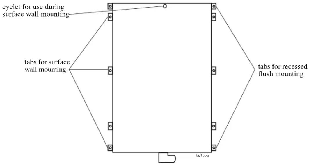
Surface mount installation
- Hang the UTS on a nail using the mounting eyelet located on the rear of the unit.
- Locate two 16 inch on center wall studs within one foot of the building circuit breaker panel.
- Mark the wall identifying the location of the mounting tabs.
- Secure the UTS to the wall using six screws appropriate for the UTS weight and the wall material on which the unit is being installed.
- Proceed to the section in this manual, Connect UTS to circuit breaker panel.
Flush mount installation
- Remove the six surface mounting tabs on the UTS using pliers to break the tabs off.
- Remove the square drive screws that secure the cover to the UTS, and remove the cover.
- Locate two 16 inch on center wall studs within one foot of the building circuit breaker panel.
- Mark the wall identifying the desired location for the UTS.
- Cut an opening in the wall to accommodate the UTS: 21.3 in x 14.25 in (54.1 cm x 36.2 cm).
- Mark the wall identifying the location of the mounting tabs.
- Position the UTS in the opening. Secure the UTS to the wall using four screws appropriate for the UTS weight and the wall material on which the unit is being installed. Use spacers supplied in the accessories kit, for installations where the wall will have wallboard applied after the UTS installation is complete.
- Replace the UTS cover removed in Step 2.
- Proceed to the section in this manual, Connect UTS to circuit breaker panel.
Connect the UTS to the circuit breaker panel
- Disconnect power to the circuit breaker panel.
- Remove the knockout on the building circuit breaker panel enclosure.
- Insert the wires extending from the UTS flexible conduit, through the hole created by the knockout in the circuit breaker panel enclosure.
- Secure the flexible conduit using the locknut on the flexible conduit.
Hardware the generator to the UTS
Prepare the power cable
- Remove the square, drive screws that secure the cover to the UTS and remove the cover.
- Strip 4 inches of insulation off the cable. This will reveal insulated conductors and one uninsulated ground conductor.
- Trim 2 inches off each of the insulated conductors. Strip .25 inch of insulation off each of the trimmed conductors.
- Select the appropriate size ring lug (supplied), and crimp it to the uninsulated ground conductor.
Hardware the terminal block

Note: For easy installation, remove the terminal block from the UTS chassis.
- Remove the two slotted nuts securing the terminal block to the UTS.
- Slide the terminal block off the threaded studs.
- Remove the knockout located on the right side of the UTS as you face it.
- Install the strain relief cable clamp (supplied). Secure the clamp with the locknut (supplied).
UTS6/6BI/10BI
Route the power cable through the strain relief installed previously. Insert the white, red and black power cable conductors into the terminal block assembly.
Tighten the screws. Torque to 10-16 in-lbs.

UTS6H
Route the power cable through the strain relief installed previously. Insert the white and black power cable conductors into the terminal block assembly.
Tighten the screws. Torque to 10-16 in-lbs.
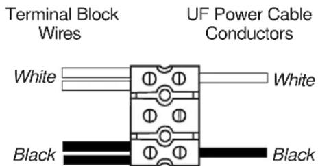
Install the terminal block in the UTS
- Slide the terminal block assembly over the two studs in the UTS. Secure the terminal block with two slotted nuts removed previously.
- Remove the nut from the ground terminal on the UTS chassis. Connect the ground wire to the ground terminal on the chassis. Secure the ground wire with the nut removed previously. Torque to 11-13 in lbs.
- UTS6/6BI/10BI models: Connect the power cable to a fixed generator or to a remote L14 connector used for a portable generator.
UTS6H models: Connect the power cable to a fixed generator or to a remote L5 connector used for a portable generator. - Install the UTS cover. Secure the cover to the UTS with the square drive screws removed previously.
- To verify that the power cable is connected and functioning properly, start the generator and check that the Generator LED on the UTS is illuminated.
- Verify that all loads connected to the UTS are receiving power.
UTS circuits
UTS6/UTS6H
Circuit

120 Vac circuits ONLY
UTS6BI
Circuit
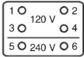
Together, circuits 5 and 6 form a dedicated 240 Vac circuit. DO NOT use these circuits as individual 120 Vac circuits.
UTS10BI
Circuit

Together, circuits 9 and 10 form a dedicated 240 Vac circuit. DO NOT use these circuits as individual 120 Vac circuits.

Note: UTS6/UTS6H - Utilizing all of the UTS circuits is not necessary. However, Circuits 5 and 6 must be connected to the building circuit panel and must receive power for the UTS to function. Circuits 5 and 6 must be connected to circuits that are in opposite phases so that 240 Vac is present across the circuits 5 and 6.
UTS6BI/UTS10BI - Utilizing all of the UTS circuits is not necessary. However, circuits 9 and 10 that together form a dedicated 240 Vac circuit must be connected to a 2-pole, 20 A circuit breaker and must receive power for the UTS to function.
120 Vac circuit wiring
Consult the UTS Wiring Plan table in the Quick Install Guide that was filled in previously.
- Locate the circuit breaker on the circuit breaker panel to be connected to circuit1 of the UTS.
- Switch the circuit breaker OFF.
- Loosen the screw securing the electrical wire, and remove the wire. DO NOT trim this wire.
- Locate wires 1 IN and 1 OUT in the bundle of wires coming from the UTS. Route these wires to the circuit breaker identified in Step 1.
- Strip off 5/8 inch insulation from the end of the wire labeled 1 OUT.
- Insert the stripped 1 OUT wire and the wire previously disconnected from the circuit breaker into a wire nut supplied in accessories kit. Twist the wire nut to ensure an electrical connection between the two wires. Tuck the wires inside the circuit breaker panel.
- Strip off 5/8 inch insulation from the end of the wire labeled 1 IN.
- Insert the stripped end of the 1 IN wire into the circuit breaker and tighten the screw to secure the wire.
- Identify the remaining 120 Vac circuits to be connected to the UTS. Repeat steps 2 through 6 for each circuit.
240 Vac circuit wiring
Consult the UTS Wiring Plan table in the Quick Install Guide that was filled in previously.
The UTS6 and UTS6H provide 120 Vac circuits only. The UTS6BI utilizes circuits 5 and 6 as a dedicated 240 Vac circuit. The UTS10BI utilizes circuits 9 and 10 as a dedicated 240 Vac circuit.
- Locate the 240 Vac, 2-pole circuit breakers on the circuit breaker panel. A 2-pole circuit breaker has an interlock that forces the two circuits to open and close together.
- Switch the circuit breakers OFF.
-
Loosen the screws securing the electrical wires, and remove the wires from the circuit breaker. DO NOT trim these wires.
-
For a UTS6BI, locate wires 5 IN, 5 OUT and 6 IN, 6 OUT in the bundle of wires coming from the UTS. Route these wires to the circuit breaker identified in Step 1.
-
For a UTS10BI, locate wires 9 IN, 9 OUT and 10 IN, 10 OUT in the bundle of wires coming from the UTS. Route these wires to the circuit breaker identified in Step 1.
-
Strip off 5/8 inch insulation from the ends of the wires in the bundle coming from the UTS:
a. for a UTS6BI, 5 OUT and 6 OUT
b. for a UTS10BI, 9 OUT and 10 OUT
- a) Insert the stripped 5 OUT wire (UTS6BI), and the wire previously disconnected from the circuit breaker into a wire nut supplied in accessories kit. Twist the wire nut to ensure an electrical connection between the two wires. Tuck the wires inside the circuit breaker panel. Repeat this process with the 6 OUT wire and the second circuit breaker in the 2-pole configuration.
b) Insert the stripped 9 OUT wire (UTS10BI), and the wire previously disconnected from the circuit breaker into a wire nut supplied in accessories kit. Twist the wire nut to ensure an electrical connection between the two wires. Tuck the wires inside the circuit breaker panel. Repeat this process with the 10 OUT wire and the second circuit breaker in the 2-pole configuration.
- Strip off 5/8 inch insulation from the ends of the wires in the bundle coming from the UTS:
a. for a UTS6BI, 5 IN and 6 IN
b. for a UTS10BI, 9 IN and 10 IN
- a) Insert the stripped end of the 5 IN wire (UTS6BI), into the circuit breaker and tighten the screw to secure the wire. Repeat this process with the 6 IN wire and the second circuit breaker in the 2-pole configuration. b) Insert the stripped end of the 9 IN wire (UTS10BI), into the circuit breaker and tighten the screw to secure the wire. Repeat this process with the 10 IN wire and the second circuit breaker in the 2-pole configuration.
Wiring schematics UTS6

Wiring schematics UTS6H
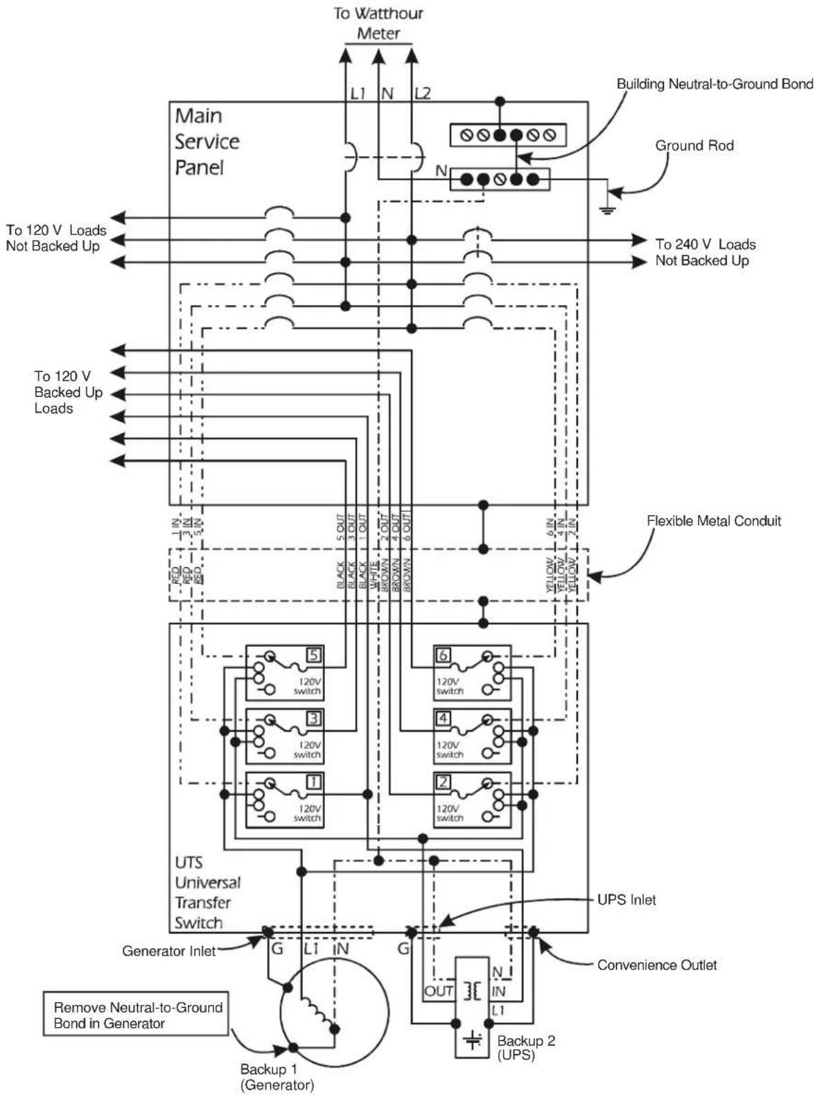
Wiring schematics UTS6BI

Wiring schematics UTS10BI

The UTS controls and indicators are located on the front of the UTS.

Control or Indicator Description
| 1 | LCD • Displays two lines with 20 | characters per line• Displays UTS status, warnings, general information• Displays the value or setting that is being entered or changed during configuration and setup |
| 2 | System Status button | Cycles the UTS through the default or selected system status options |
| 3 | System Setup button Used to configure the UTS system options | |
| 4 | Circuit Status button | Cycles the UTS through the circuits displaying the status of each on the LCD |
| 5 | Circuit Setup button Used to configure the UTS individual circuit options | |
| 6 | Down/Up arrow buttons | Used to scroll through steps for configuration and to scroll between status and informational displays |
| 7 | Source LEDsUtilityGeneratorUPS | • Solid green LED illumination indicates that the power source is ON and is functioning normally• No LED illumination indicates that the power source is OFF or is outside specified limits• A flashing green LED indicates that a fault condition exists for that power source, and should be corrected |
| 8 | Circuit LEDs The number of circuit LEDs varies dependent on the model of UTS• Red LED illumination indicates that the UTS circuit is receiving power from one of the power sources• No illumination indicates that circuit is receiving no power• A flashing red LED indicates that a fault condition exists and should be corrected | |
The power connectors are located on the front of the UTS.
UTS10BI

Connect Power to the UTS
Verify circuit connections
- Reconnect power to the circuit breaker panel and switch ON all of the circuit breakers.
- Confirm the following:
a. UTS6/UTS6H - confirm that the circuits supporting the UTS circuits 5 and 6 are switched ON
b. UTS6BI - confirm that the 2-pole circuit supporting the UTS circuits 5 and 6 is switched ON
c. UTS10BI - confirm that the 2-pole circuit supporting the UTS circuits 9 and 10 is switched ON
Connect the UTS power cord to utility power
When the UTS is connected to utility power these two messages appear on the LCD screen and the Utility Source LED will illuminate.
APC - LEGENDARY RELIABILITY
UTS UNIVERSAL TRANSFER SWITCH
Initial Setup
After several initializing LCD screens appear and the Utility Source LED illuminates, the LCD will display this message:
UTS Setup Wizard
STARTING UTS WIZARD - ANY KEY TO CONTINUE
The Setup Wizard enables the user to:
• view the factory default parameter settings for the UTS
• change the parameters for the UTS
- reset all parameters to the factory default settings

Note: The settings and values selected will change immediately after an arrow button is pressed.
The LCD will revert back to the starting display message after 30 seconds with no activity.
Backup1 Source Type
The factory default setting is GENERATOR. The generator inlet located on the front of the UTS provides connectivity for a backup power source. The system setup has three options for backup power:
BACKUP1 SOURCE TYPE? GENERATOR
- Generator
• U P S - Other
Use the down/up arrow keys to select the preferred backup power source. APC recommends the use of a generator for BACKUP1.
Backup1 (Generator) Power Rating
Use the down/up arrow keys to set the correct power rating for the backup power source connected to the UTS.
GEN POWER RATING: 0-12000 WATTS
There are three levels for rapid rating increment changes. Press and hold the status system button to adjust the power rating and to move through the three levels described here.
Level 1 increases or decreases the rating by 5 Watts.
Level 2 increases or decreases the rating by 10 Watts.
Level 3 increases or decreases the rating by 100 Watts.
Generator Start Mode
Press the System Setup button. For generators featuring manual start, use the MANUAL setting. Press the down or up arrow key to change to AUTO setting.
GEN START AUTO/MAN? MANUAL
For generators featuring automatic start, use the AUTO setting.
The UTS has a remote automatic start/stop function for use with generators having the following features:
- automatic start
- automatic choke
- remote start/stop capability
Refer to the documentation in the Generator Automatic Start/Stop Kit for automatic generator configuration instructions.
Backup2 Source Type
The factory default setting is UPS. The backup2 power source inlet, located on the front of the UTS is labeled UPS Inlet as a UPS is the preferred BACKUP2 power source.
BACKUP2 SOURCE TYPE? UPS
The system setup has three options for backup power:
- Generator
- UPS (recommended BACKUP2 power source)
- Other
Use the down/up arrow keys to select the preferred backup power source.

NOTE: It is recommended that a UPS be used as BACKUP2 SOURCE TYPE. A UPS provides continuous battery backup power during utility brownouts, sags, surges, and power outages.
Without the use of a UPS, fully automatic operation of the UTS cannot be guaranteed.
If a UPS is not selected for the BACKUP2 power source be sure that the UNINTERRUPTIBLE option under Circuit Setup Option 2 is not selected.
Backup2 (UPS) Power Rating
Once the BACKUP2 SOURCE TYPE has been selected, that source type will appear in the power rating display message. Use the down/up arrow keys to set the correct power rating for the backup2 power source connected to the UTS.
UPS POWER RATING? 0-1800 WATTS
There are three levels for rapid rating increment changes. Press and hold the down or up arrow key to adjust the power rating and to move through the three levels described here. To revert back to level 1 release the down arrow key then press and hold the down arrow key.
Level 1 increases or decreases the rating by 5 Watts.
Level 2 increases or decreases the rating by 10 Watts.
Level 3 increases or decreases the rating by 100 Watts.
Circuit 1 setup
Use the down/up arrow keys to scroll through the list of load types. Select the load type to be supported by circuit 1.
CKT1 LOAD TYPE? LIGHT
Circuit 2 setup
Use the down/up arrow keys to scroll through the list of load types. Select the load type to be supported by circuit 2.
Repeat this process for all of the circuits.

NOTE: UTS6/UTS6H - provide 120 Vac circuits only
UTS6BI - together, circuits 5 and 6 form a dedicated 240 Vac circuit. DO NOT use these circuits as individual 120 Vac circuits.
UTS10BI - Together, circuits 9 and 10 form a dedicated 240 Vac circuit. DO NOT use these circuits as individual 120 Vac circuits.
Once all of the UTS parameters have been set, the Setup Wizard ends indicating that the UTS is setup and ready to operate.
EXITING WIZARD UTS IS SETUP & READY
System Status Verification
The UTS system status and the status of up to three power sources can be viewed by pressing the System Status button located on the front of the UTS. To navigate through the system status menus, press the System Status button after viewing the information on the LCD.
LCD displays the input voltages from the UTILITY through the main load center for PHASE1 and PHASE2.
UTILITY PHASE1: 120V
UTILITY PHASE2: 120V
LCD displays the SYSTEM LOAD (total power), that is being drawn through the UTS AND the power drawn by each phase - PH1 and PH2
This information provides verification that the phases are balanced.
SYSTEM LOAD: 2400W
PH1: 1050W PH2: 1350W
LCD displays the BACKUP1 source voltages for GEN PHASE1 and GEN PHASE2.
GEN PHASE1: 117V
GEN PHASE2: 118V
LCD displays the BACKUP1 source power outputs for GEN PHASE1 and GEN PHASE2.
GEN PHASE1: 480W
GEN PHASE2: 750W
LCD displays the UPS VOLTAGE and UPS LOAD for the BACKUP2 source (normally a UPS).
UPS VOLTAGE: 120V
UPS POWER: 200W
LCD displays the MODEL# (model number), and SN# (serial number) of the UTS.
MODEL#: UTS10BI
SN#: JB06008004272
LCD displays the FW VER (firmware version) installed in the UTS.
UTS FW VER: 1
UI FW VER: 1
LCD displays the MFG DATE (date of manufacture) for the UTS.
MFG DATE: xx/xx/xxxx
Circuit status verification
The status of each circuit on the UTS can be viewed by pressing the Circuit Status button located on the front of the UTS. To navigate through the circuits, press the Circuit Status button after viewing the status of each circuit.
Example: CK1SRC (circuit1 source) indicates the power source (utility power), plus the status of circuit1: number of Amps, number of kWh, and number of Watts.
CK1SRC: UTILITY AMP: 1
KWH: 2:35 WATTS: 120
UTS10BI

Generator

WARNING: Home generator backup systems should be installed by a licensed electrician.
Locate the generator outside a building and at least 10 feet away from buildings, windows, and doors. Failure to follow this safety rule may result in illness or death from breathing carbon monoxide.
The generator must have three to four feet of space around all sides and the top to ensure proper ventilation.
Locate the generator on a dry, level surface protected from rain and excessive dust.
Fuel for gas operated generators must be stored in approved containers, and in well ventilated conditions.
Refer to the generator user documentation for additional safety precautions.
For generators featuring automatic start, use the AUTO setting.
The UTS has a remote automatic start/stop function for use with generators having the following features:
- automatic start
- automatic choke
- remote start/stop capability
Contact APC at www.apc.com to order the APC Generator Automatic Start/Stop Kit.
To hardwire a generator to the UTS, contact APC at www.apc.com to order the APC UTS Automatic Remote Start/Stop Kit.
For details on generator installation and specifications refer to the generator documentation.
Recommended Generator to UTS Connectors and Cables
| UTS Model Connector | Type Cable | |
| UTS6/UTS6BI L14-20 Rubber jacketed cable | Four 12 AWG stranded connectors | |
| UTS6H L5-30 Rubber jacketed cable | Three 10 AWG stranded connectors | |
| UTS10BI L14-30 Rubber jacketed cable | Four 10 AWG stranded connectors | |
UPS
The UTS is equipped with a standard IEC 320, 120 Vac inlet specifically intended for use with a UPS. Use the power cord supplied in the accessories kit to connect the UPS to the UTS.
The UTS is equipped with a standard NEMA 5-15, 120 Vac Convenience outlet for connecting a UPS or another selected load to the UTS. The Convenience outlet can utilize utility power or generator power, providing an uninterruptible power supply during a power outage or fluctuation.
If any circuits are to be configured as uninterruptible, a UPS must be used as the Backup2 power source. The UPS input cord should plug into the convenience outlet to allow the UPS battery to charge while operating on generator power.
For details on UPS installation and specifications refer to the UPS documentation.
Other backup power sources
The UTS can utilize backup power sources other than a generator and a UPS. Contact APC at www.apc.com for information on alternative backup power sources.
Troubleshooting
Use this chart to solve minor UTS problems.
Refer to www.apc.com for assistance with complex UTS problems.
Problem and Possible Cause Solution
| Problem: The UTS conduit is too long or too short | |
| Cause: The UTS was not installed at the recommended one foot distance from the building circuit breaker panel. | Conduit too long: have a licensed electrician cut the conduit to shorten the length.Conduit too short: have a licensed electrician add conduit to the existing conduit utilizing the proper use of wire nuts and junction boxes. Adhere to all national and local electrical codes. |
| Problem: The amperage of a circuit must be changed to accommodate the connected load | |
| Cause: A 15 A fuse is installed in the circuit, but the connected load requires the use of a 20 A fuse.Cause: A 20 A fuse is installed in the circuit, but the connected load requires the use of a 15 A fuse. | Remove the UTS cover and replace the existing fuse with a fuse of correct amperage.Use the Circuit Setup button to reset the affected circuit. Failure to reset the amperage for the affected circuit will cause nuisance circuit tripping, or a UTS overload condition. |
| Problem: The UTS does not turn on | |
| Cause: Incorrect wiring to circuits. | UTS6/UTS6H - Utilizing all of the UTS circuits is not necessary. However, Circuits 5 and 6 must be connected to the building circuit panel and must receive power from opposite phases for the UTS to function.UTS6BI/UTS10BI - Utilizing all of the UTS circuits is not necessary. However, the dedicated 240 Vac circuits must be connected to the building circuit panel and must receive power for the UTS to function. |
| Problem: The UTS does not receive power from the generator | |
| Cause: The generator has been incorrectly connected to the UTS. | Check to be sure the correct wiring configuration has been used. |
| Cause: The generator output is not 120 Vac/240 Vac single phase. This is not applicable to the UTSS6H. | Check the specifications of the generator. Only 120 Vac/240 Vac single phase generators can be used with the UTS. |
| Problem: The UTS does not receive power from the UPS | |
| Cause: The UPS is overloaded and has shutdown. | Disconnect the circuits set as uninterruptible one at a time until the UPS begins operating. |
| Problem: The load does not receive power during a power outage | |
| Cause: A UTS configuration error is present. | Check the UTS system and circuit configurations and correct any errors.Common errors include:circuits set as uninterruptible when there is no UPS connected to the UTS.ALM is enabled and the settings are out of specified range.Refer to the Operation Manual for details on ALM settings. |
Problem and Possible Cause Solution
| Problem: UTS configuration errors are found | |
| Cause: Initial UTS configuration is found to be incorrect. | Reset the UTS to the factory defaults and begin the setup process again. Use the System Setup button to scroll through the system setup options. Stop at RESET TO FACTORY DEFAULTS. Use the down/up arrow keys to start the Setup Wizard. |
| Problem: A circuit is mislabeled while using the Setup Wizard | |
| Cause: An error is made while configuring the UTS circuits. | Reset the UTS to the factory defaults and begin the setup process again. Use the System Setup button to scroll through the system setup options. Stop at RESET TO FACTORY DEFAULTS. Use the down/up arrow keys to start the Setup Wizard.Change the circuit labels. Refer to Circuit Configuration and Setup in the Operation Manual for details. |
| Problem: The circuit switches click on and off as power is supplied intermittently to some loads | |
| Cause: The neutral wire is missing or configured incorrectly. | Connect the neutral wire correctly. |
| Problem: There is no power to some loads while operating on utility power, and the overload warning appears on the LCD | |
| Cause: The current going through the UTS exceeds the maximum rated specifications. | Reduce the load. |
UTS Wiring Plan
| Load Description | Load Voltage120 V/240 V | Breaker Number | Load PowerWatts or Amps | UTSCircuitsEven Odd | Notes | |
| Even Circuits Total: | ||||||
| Odd Circuits Total: | ||||||
| Total Power: | ||||||
Backup Power Sources Configuration
| Type | Power | Make/Model | Overload Delay1 | Start Relay2 | Stop Relay2 | Start Delay2 | Stop Delay2 | |
| UPS/Gen/Other | Watts | - | Seconds | Normally open/closed | Seconds or Minutes | |||
| BACKUP1 | ||||||||
| BACKUP2 | ||||||||
| Note1 : Refer to the System Configuration and Setup section in the Operation ManualNote2 : These entries apply only to auto start generators. | ||||||||
The tables on this page and the previous page are intended to be filled in and taped to the inside cover of the building circuit breaker panel enclosure.
UTS6/UTS6H
| Circuit No. Load | Description |
| 1 | |
| 2 | |
| 3 | |
| 4 | |
| 5 | |
| 6 |
UTS6BI
| Circuit No. Load | Description |
| 1 | |
| 2 | |
| 3 | |
| 4 | |
| 5/6 |
UTS10BI
| Circuit No. Load | Description |
| 1 | |
| 2 | |
| 3 | |
| 4 | |
| 5 | |
| 6 | |
| 7 | |
| 8 | |
| 9/10 |
Service
If the unit requires service do not return it to the dealer. Follow these steps:
-
Review the problems discussed in Troubleshooting to eliminate common problems.
-
If the problem persists, contact APC Customer Support through the
APC Web site, www.apc.com.
- Note the model number of the unit, the serial number located on the front of the unit, and the date purchased. If you call APC Customer Support, a technician will ask you to describe the problem and attempt to solve it over the phone. If this is not possible, the technician will issue a Returned Material Authorization Number (RMA#).
-
If the unit is under warranty, repairs are free.
– Procedures for servicing or returning products may vary internationally. Refer to the APC Web site for country specific instructions. -
Pack the unit in its original packaging. If this is not available:
-
Pack the unit carefully to avoid damage in transit. Never use Styrofoam beads for packaging.
– Damage sustained in transit is not covered under warranty. -
Mark the RMA# on the outside of the package.
-
Return the unit by insured, prepaid carrier to the address given to you by Customer Support.
Regulatory Information
Radio Frequency Warnings
FCC Class B Compliance Notice
This equipment has been tested and found to comply with the limits for a Class B digital device, pursuant to Part 15 of the FCC Rules. These limits are designed to provide reasonable protection against harmful interference in a residential installation. This equipment generates, uses and, can radiate radio frequency energy and if not installed and used in accordance with the instructions, may cause harmful interference to radio communications. However, there is no guarantee that interference will not occur in a particular installation. If this equipment does cause harmful interference to radio and television reception, which can be determined by turning the equipment off and on, the user is encouraged to try to correct the interference by one or more of the following measures.
- Reorient or relocate the receiving antenna.
- Increase the separation between the equipment and receiver.
- Connect the equipment into an outlet on a circuit different from that to which the receiver is connected.
- Consult the dealer or an experienced radio/TV technician for help.
Two-Year Warranty
The limited warranty provided by American Power Conversion (APC®) in this statement of Limited Factory Warranty applies only to products you purchase for your commercial or industrial use in the ordinary course of your business.
Terms of warranty
APC warrants its products to be free from defects in materials and workmanship for a period of two years from the date of purchase. The obligation of APC under this warranty is limited to repairing or replacing, at its sole discretion, any such defective products. This warranty does not apply to equipment that has been damaged by accident, negligence or misapplication or has been altered or modified in any way. Repair or replacement of a defective product or part thereof does not extend the original warranty period. Any parts furnished under this warranty may be new or factory-remanufactured.
Non-transferable warranty
This warranty extends only to the original purchaser who must have properly registered the product. The product may be registered at the APC Web site, www.apc.com.
Exclusions
APC shall not be liable under the warranty if its testing and examination disclose that the alleged defect in the product does not exist or was caused by end user or any third person misuse, negligence, improper installation or testing. Further, APC shall not be liable under the warranty for unauthorized attempts to repair or modify wrong or inadequate electrical voltage or connection, inappropriate on-site operation conditions, corrosive atmosphere, repair, installation, start-up by non-APC designated personnel, a change in location or operating use, exposure to the elements, Acts of God, fire, theft, or installation contrary to APC recommendations or specifications or in any event if the APC serial number has been altered, defaced, or removed, or any other cause beyond the range of the intended use.
THERE ARE NO WARRANTIES, EXPRESS OR IMPLIED, BY OPERATION OF LAW OR OTHERWISE, OF PRODUCTS SOLD, SERVICED OR FURNISHED UNDER THIS AGREEMENT OR IN CONNECTION HEREWITH. APC DISCLAIMS ALL IMPLIED WARRANTIES OF MERCHANTABILITY, SATISFACTION AND FITNESS FOR A PARTICULAR PURPOSE. APC EXPRESS WARRANTIES WILL NOT BE ENLARGED, DIMINISHED, OR AFFECTED BY AND NO OBLIGATION OR LIABILITY WILL ARISE OUT OF, APC RENDERING OF TECHNICAL OR OTHER ADVICE OR SERVICE IN CONNECTION WITH THE PRODUCTS. THE FOREGOING WARRANTIES AND REMEDIES ARE EXCLUSIVE AND IN LIEU OF ALL OTHER WARRANTIES AND REMEDIES. THE WARRANTIES SET FORTH ABOVE CONSTITUTE APC SOLE LIABILITY AND PURCHASER EXCLUSIVE REMEDY FOR ANY BREACH OF SUCH WARRANTIES. APC WARRANTIES EXTEND ONLY TO PURCHASER AND ARE NOT EXTENDED TO ANY THIRD PARTIES.
IN NO EVENT SHALL APC, ITS OFFICERS, DIRECTORS, AFFILIATES OR EMPLOYEES BE LIABLE FOR ANY FORM OF INDIRECT, SPECIAL, CONSEQUENTIAL OR PUNITIVE DAMAGES, ARISING OUT OF THE USE, SERVICE OR INSTALLATION, OF THE PRODUCTS, WHETHER SUCH DAMAGES ARISE IN CONTRACT OR TORT, IRRESPECTIVE OF FAULT, NEGLIGENCE OR STRICT LIABILITY OR WHETHER APC HAS BEEN ADVISED IN ADVANCE OF THE POSSIBILITY OF SUCH DAMAGES. SPECIFICALLY, APC IS NOT LIABLE FOR ANY COSTS, SUCH AS LOST PROFITS OR REVENUE, LOSS OF EQUIPMENT, LOSS OF USE OF EQUIPMENT, LOSS OF SOFTWARE, LOSS OF DATA, COSTS OF SUBSTITUENTS, CLAIMS BY THIRD PARTIES, OR OTHERWISE.
NO SALESMAN, EMPLOYEE OR AGENT OF APC IS AUTHORIZED TO ADD TO OR VARY THE TERMS OF THIS WARRANTY. WARRANTY TERMS MAY BE MODIFIED, IF AT ALL, ONLY IN WRITING SIGNED BY AN APC OFFICER AND LEGAL DEPARTMENT.
Warranty claims
Customers with warranty claims issues may access the APC customer support network through the Support page of the APC Web site, www.apc.com/support. Select your country from the country selection pull-down menu. Open the Support tab at the top of the Web page to obtain contact information for customer support in your region.
APC Worldwide Customer Support
Customer support for this or any other APC product is available at no charge in any of the following ways:
- Visit the APC Web site to access documents in the APC Knowledge Base and to submit customer support requests.
- www.apc.com (Corporate Headquarters)
Connect to localized APC Web sites for specific countries, each of which provides customer support information. - www.apc.com/support/
Global support searching APC Knowledge Base and using e-support. - Contact the APC Customer Support Center by telephone or e-mail.
- Local, country-specific centers: go to www.apc.com/support/contact for contact information.
For information on how to obtain local customer support, contact the APC representative or other distributors from whom you purchased your APC product.
- Site Preparation and Installation Guide
- Universal Transfer Switch
- About this product
- Protect your investment
- Recommended Tools Recommended Cables
- UTS6/6BI/10BI models
- UTS6H models
- Inventory
- Safety and Regulatory Information - save this information
- Safety Precautions
- Select a location
- Determine circuit usage
- Note: Special note regarding Circuit1.
- Backup power sources
- Generators
- Generator Load Balance
- Uninterruptible Power Supply (UPS)
- Installation
- Adhere to all national and local electrical codes.
- Surface mount installation
- Flush mount installation
- Connect the UTS to the circuit breaker panel
- Hardware the generator to the UTS
- Prepare the power cable
- Hardware the terminal block
- UTS6/6BI/10BI
- UTS6H
- Install the terminal block in the UTS
- UTS circuits
- Vac circuit wiring
- Vac circuit wiring
- Connect Power to the UTS
- Verify circuit connections
- Connect the UTS power cord to utility power
- Initial Setup
- UTS Setup Wizard
- Backup1 Source Type
- Backup1 (Generator) Power Rating
- Generator Start Mode
- Backup2 Source Type
- Backup2 (UPS) Power Rating
- Circuit 1 setup
- Circuit 2 setup
- System Status Verification
- Circuit status verification
- Generator
- UPS
- Other backup power sources
- Troubleshooting
- Service
- Regulatory Information
- Radio Frequency Warnings
- FCC Class B Compliance Notice
- Two-Year Warranty
- Terms of warranty
- Non-transferable warranty
- Exclusions
- Warranty claims
- APC Worldwide Customer Support
Brand : APC
Model : UTS6H
Category : Interrupteur de transfert électrique