DXTC18X426A-20 - Air Conditioning Daizuki - Free user manual and instructions
Find the device manual for free DXTC18X426A-20 Daizuki in PDF.


| Brand | Daizuki |
| Model | DXTC18X426A-20 |
| Product Type | Split Air Conditioner (Inverter) |
| Cooling Capacity (BTU/h) | 18,000 |
| Power Supply (V/Hz/Ph) | 220-240V / 50Hz / 1Ph |
| Refrigerant Type | R32 |
| Indoor Unit Dimensions (WxHxD in mm) | 900 x 300 x 200 (approx) |
| Outdoor Unit Dimensions (WxHxD in mm) | 770 x 550 x 300 (approx) |
| Indoor Unit Weight (kg) | 12 |
| Outdoor Unit Weight (kg) | 35 |
| Max Pipe Length (m) | 25 |
| Max Height Difference (m) | 10 |
| Pipe Size Liquid/Gas (inch) | 1/4" / 1/2" |
| Modes | Auto, Cool, Dry, Heat, Fan only, ECO, Turbo |
| Fan Speeds | Auto, Low, Mid, High, Mute |
| Timer | 24-hour programmable ON/OFF timer |
| Sleep Function | Yes, with sleep curve for 10 hours |
| Wi-Fi Control | Optional (Smart Life / Gubei app compatible) |
| Self-Cleaning | Yes (anti-frost and anti-bacterial) |
| Air Filter | Washable, easy access |
| Energy Efficiency | Inverter technology, high SEER |
| Warranty | Standard manufacturer warranty (check manual) |
Frequently Asked Questions - DXTC18X426A-20 Daizuki
User questions about DXTC18X426A-20 Daizuki
0 question about this device. Answer the ones you know or ask your own.
Ask a new question about this device
Download the instructions for your Air Conditioning in PDF format for free! Find your manual DXTC18X426A-20 - Daizuki and take your electronic device back in hand. On this page are published all the documents necessary for the use of your device. DXTC18X426A-20 by Daizuki.
USER MANUAL DXTC18X426A-20 Daizuki
Inverter air conditioner
Service Manual
Models
DXTC09C416-20/DXTC09C416-20
DXTC09E426-20/DXTC09C426-20
DXTC12E416-20/DXTC12C416-20
DXTC12E426-20/DXTC12C426-20
DXTC18E426A-20/DXTC18C426A-20
DXTC24E426A-20/DXTC24C426A-20
DXTC36E426A-17/DXTC36C426A-17
CONTENTS
Part I Technical Information....3
- Important Notice .... 3
- Refrigeration cycle diagram 4
- Electric Diagram....5
3.1 Wiring diagram 5
3.2 Remote Controller 12
- Electronic Controller Introduction ...... 13
4.1 Electronic Controller 13
4.2 WIFI OPERATION MAUAL 19
PART II Installation and Maintenance 20
- Notes for installation and maintenance.... 20
2 Installation 27
2.1 Installation Dimension Diagram 27
2.2 Accessory 28
2.3 Tools 28
2.4 Position.... 29
2.5 Electricity and wiring 29
2.6 IDU Installation.... 29
2.7 ODU Installation.... 32
2.8 Vacuum and gas leakage test.... 33
2.9 Final test 33
- Maintenance 34
3.1 Failure code 34
3.2 Trouble shooting.... 36
- Disassembly IDU & ODU 59
4.1. IDU Disassembly 59
4.2 ODU Assembly 63
APPENDIX 69
Appendix 1 The comparison table of Celsius-Fahrenheit temperature....69
Appendix 2 The Pipe length and Gas charging 69
Appendix 3 Pipes Flaring 70
Appendix 4 THERMISTOR TEMPERATURE CHARACTERISTICS....71
Part I Technical Information
1. Important Notice
This service manual is intended for use by individuals possessing adequate backgrounds of electrical, electronic and mechanical experience. Any attempt to repair the appliance may result in personal injury and property damage. The manufacturer or seller cannot be responsible for the interpretation of this information, nor can it assume any liability in connection with its use.
The information, specifications and parameter are subject to change due to technical modification or improvement without any prior notice. The accurate specifications are presented on the nameplate label.
2. Refrigeration cycle diagram
Cool only
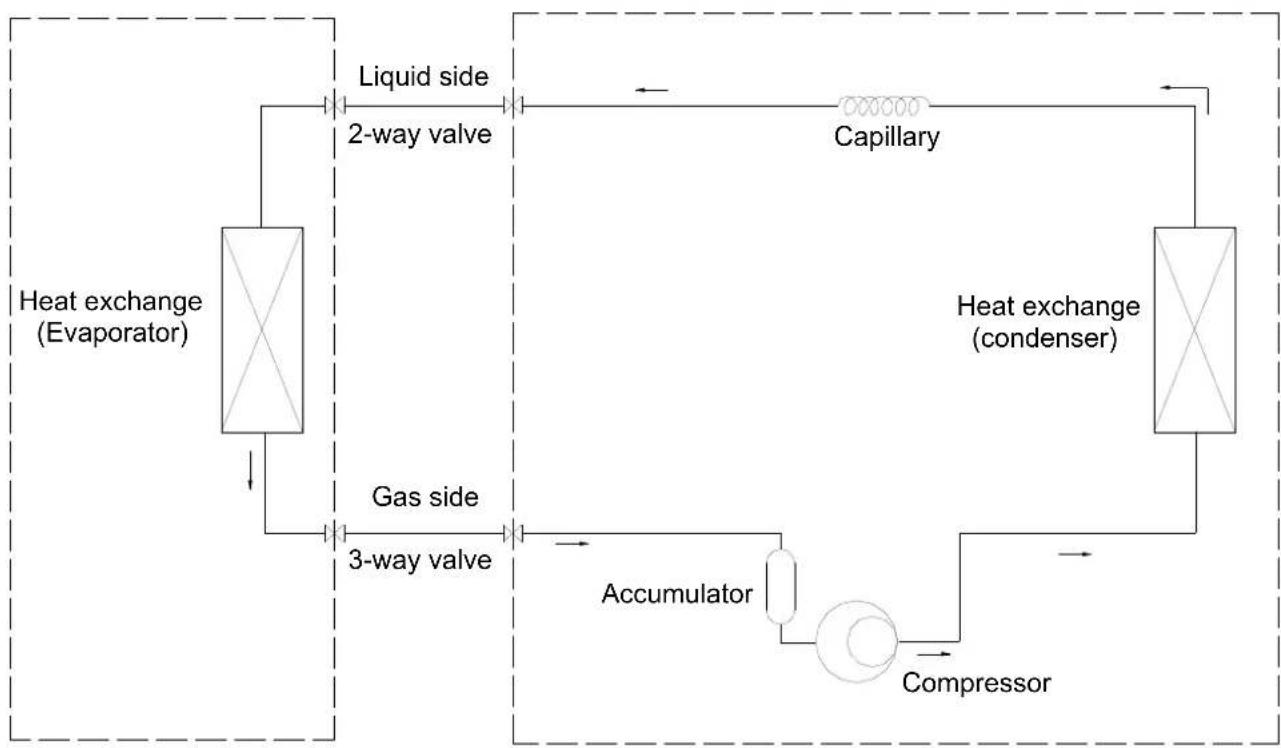
flowchart
graph TD
    A["Heat exchange (Evaporator)"] --> B["2-way valve"]
    B --> C["Liquid side"]
    C --> D["Capillary"]
    D --> E["Heat exchange (condenser)"]
    E --> F["Compressor"]
    F --> G["Accumulator"]
    G --> H["3-way valve"]
    H --> I["Gas side"]
    I --> J["3-way valve"]
    J --> K["Heat exchange (Evaporator)"]
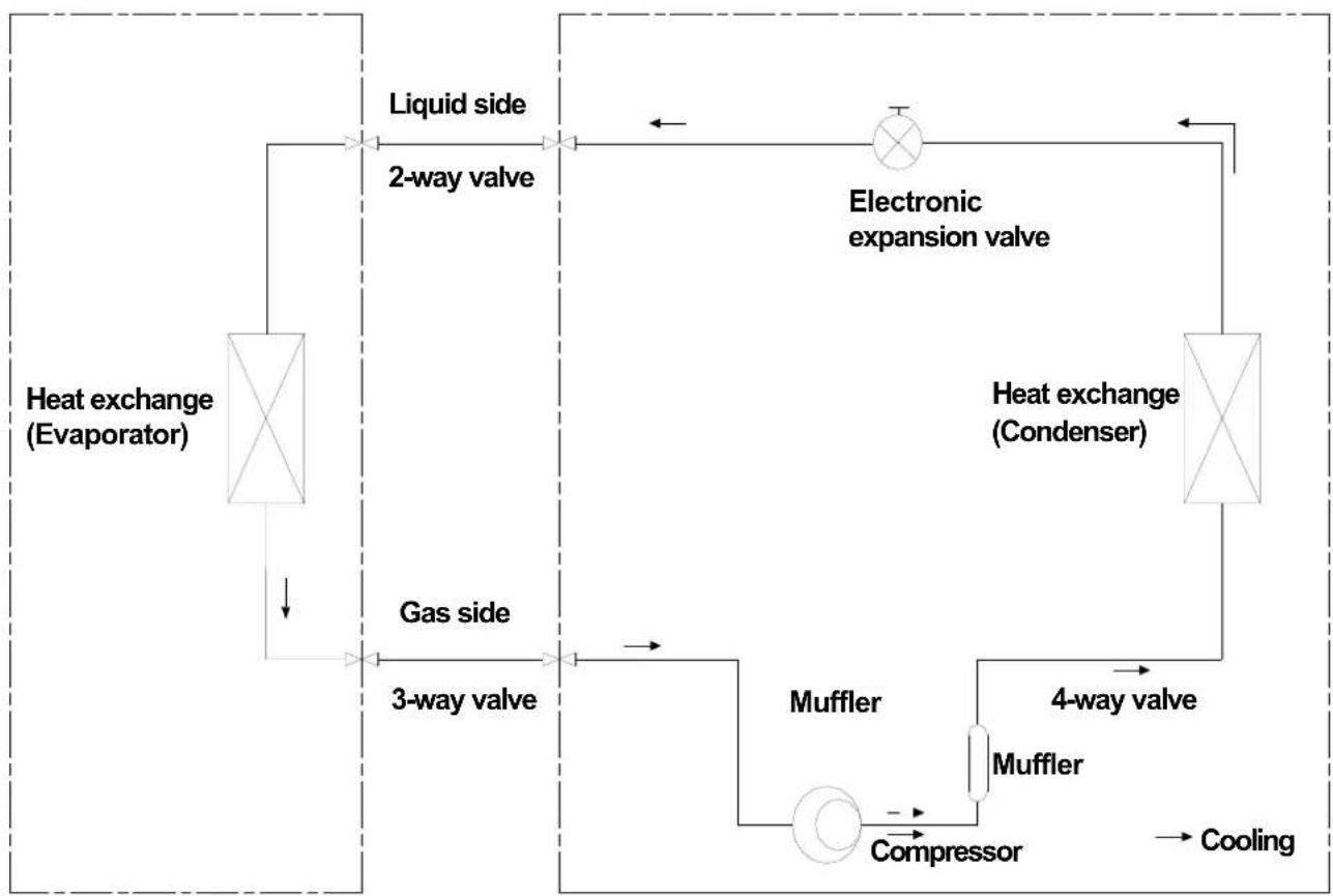
flowchart
graph TD
    A["Heat exchange (Evaporator)"] --> B["Liquid side"]
    B --> C["2-way valve"]
    C --> D["Electric expansion valve"]
    D --> E["Heat exchange (Condenser)"]
    E --> F["4-way valve"]
    F --> G["Compressor"]
    G --> H["Cooling"]
    I["3-way valve"] --> J["Muffler"]
    J --> G
    K["Gas side"] --> L["Muffler"]
    L --> G
3. Electric Diagram
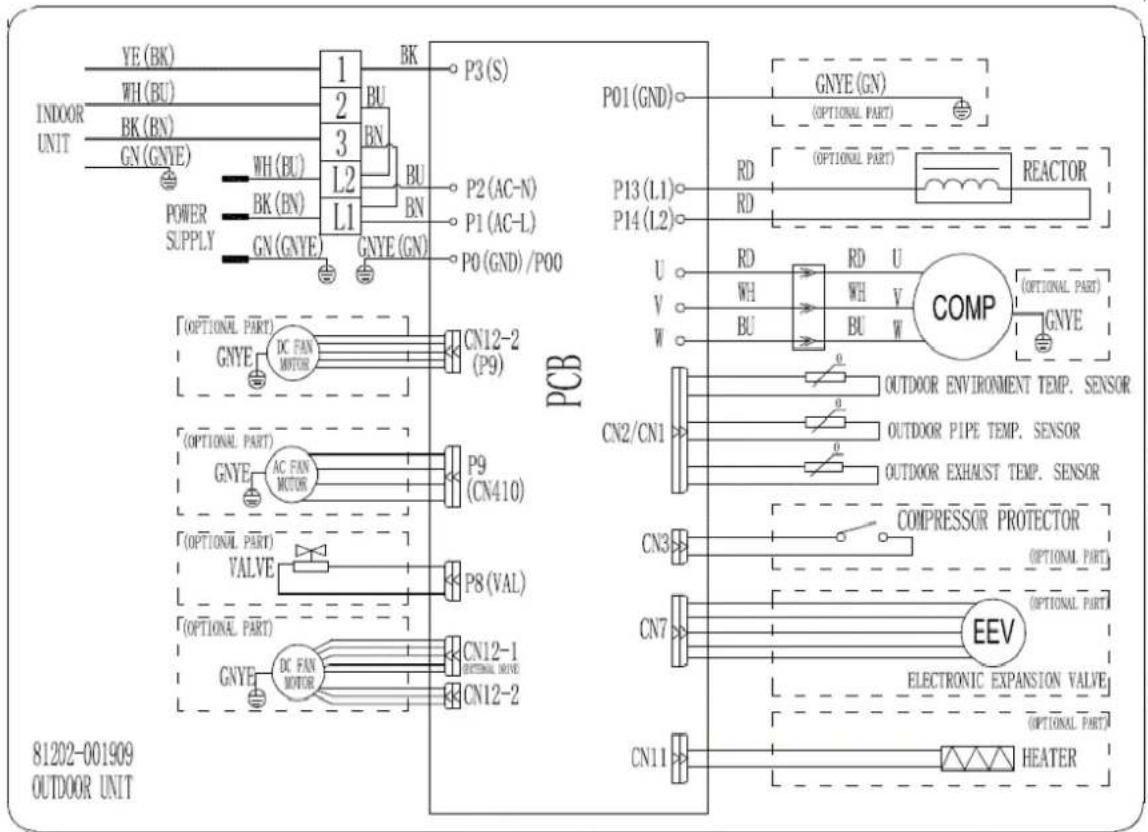
3.1 Wiring diagram
INDOOR MODEL: DXTC09E426-20
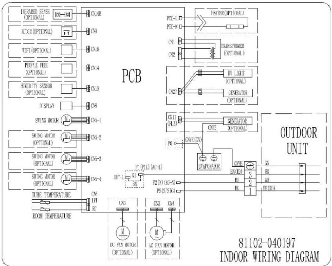
flowchart
graph TD
    subgraph PCB
        A["INFRARED SENSE (OPTIONAL)"] --> B["CN14B"]
        C["AUDIO (OPTIONAL)"] --> D["CN9"]
        E["WIFI (OPTIONAL)"] --> F["CN16"]
        G["PEOPLE FEEL (OPTIONAL)"] --> H["CN14"]
        I["HUMIDITY SENSOR (OPTIONAL)"] --> J["CN19"]
        K["DISPLAY"] --> L["CN8"]
        M["SWING MOTOR"] --> N["CN5-1"]
        O["SWING MOTOR (OPTIONAL)"] --> P["CN5-2"]
        Q["SWING MOTOR (OPTIONAL)"] --> R["CN5-3"]
        S["SWING MOTOR (OPTIONAL)"] --> T["CN5-4"]
        U["TUBE TEMPERATURE"] --> V["CN6 IPT RT"]
        W["ROOM TEMPERATURE"] --> X["CN6"]
    end

    subgraph OUTDOOR UNIT
        Y["HEATER (OPTIONAL)"] --> Z["CN1"]
        AA["TRANSFORMER (OPTIONAL)"] --> AB["CN2"]
        AC["UV LIGHT (OPTIONAL)"] --> AD["CN27"]
        AE["GENERATOR (OPTIONAL)"] --> AF["CN11 (FLZ)"]
        AG["GENERATOR (OPTIONAL)"] --> AH["GNE"]
        AI["GNE (GN)"] --> AJ["P0"]
        AK["EVAPORATOR"] --> AL["P1 (P1L) (AC-L)"]
        AM["P2 (N) (AC-N)"] --> AN["P2 (N) (AC-N)"]
        AO["PS (S/SIG)"] --> AP["PS (S/SIG)"]
        AQ["BN (RD)"] --> AR["BU"]
        AS["BK"] --> AT["BK"]
        AU["GN"] --> AV["HK"]
        AW["WH"] --> AX["YE (RD)"]
    end

    style PCB fill:#f9f,stroke:#333
    style OUTDOOR UNIT fill:#ccf,stroke:#333
    style 81102-040197 INDoor WIRING DIAGRAM
OUTDOOR MODEL: DXTC09C426-20
INDOOR MODEL: DXTC09C416-20
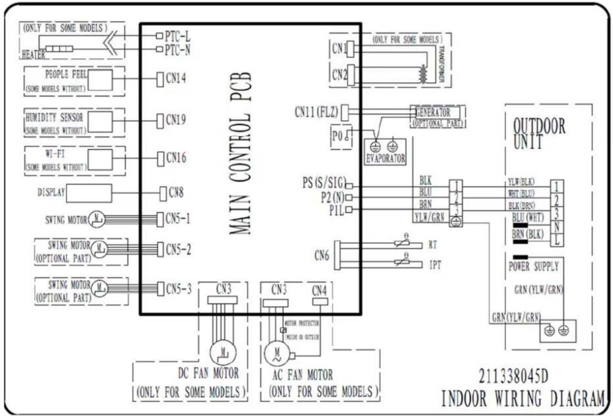
flowchart
graph TD
    A["MAIN CONTROL PCB"] --> B["OUTDOOR UNIT"]
    A --> C["INDOOR WIRING DIAGRAM"]
    subgraph Power Supply
        D["POWER SUPPLY"]
        E["GRN (YLW/GRN)"]
        F["GRN (YLW/GRN)"]
    end

    subgraph Control
        G["DC FAN MOTOR (ONLY FOR SOME MODELS)"]
        H["AC FAN MOTOR (ONLY FOR SOME MODELS)"]
        I["MOTOR PROTECTION (MODE OR OUTSIDE)"]
        J["M"]
    end

    subgraph Outdoor
        K["BLK BLU BRN YLW/GRN"]
        L["PT IPT"]
        M["PTC-L PTC-N"]
        N["CN1"]
        O["CN2"]
        P["CN11 (FLZ)"]
        Q["GENERATOR (OPTIONAL PART)"]
        R["PS (S/SIG)"]
        S["P2 (N)"]
        T["P1L"]
        U["CN6"]
    end

    style A fill:#f9f,stroke:#333
    style B fill:#ccf,stroke:#333
    style C fill:#cfc,stroke:#333
    style D fill:#fcc,stroke:#333
    style E fill:#fcc,stroke:#333
    style F fill:#fcc,stroke:#333
    style G fill:#fff,stroke:#333
    style H fill:#fff,stroke:#333
    style I fill:#fff,stroke:#333
    style J fill:#fff,stroke:#333
    style K fill:#fff,stroke:#333
    style L fill:#fff,stroke:#333
    style M fill:#fff,stroke:#333
    style N fill:#fff,stroke:#333
    style O fill:#fff,stroke:#333
    style P fill:#fff,stroke:#333
    style Q fill:#fff,stroke:#333
    style R fill:#fff,stroke:#333
    style S fill:#fff,stroke:#333
    style T fill:#fff,stroke:#333
    style U fill:#fff,stroke:#333
    style V fill:#fff,stroke:#333
    style W fill:#fff,stroke:#333
    style X fill:#fff,stroke:#333
    style Y fill:#fff,stroke:#333
    style Z fill:#fff,stroke:#333
OUTDOOR MODEL: DXTC09C416-20
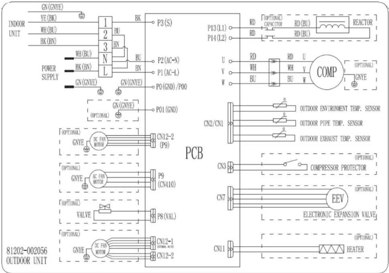
INDOOR MODEL: DXTC12E416-20
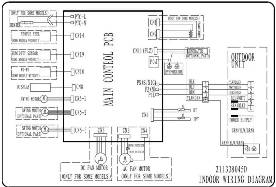
flowchart
graph TD
    A["MAIN CONTROL PCB"] --> B["OUTDOOR UNIT"]
    A --> C["DC FAN MOTOR (ONLY FOR SOME MODELS)"]
    A --> D["AC FAN MOTOR (ONLY FOR SOME MODELS)"]
    A --> E["SWING MOTOR (OPTIONAL PART)"]
    A --> F["SWING MOTOR (OPTIONAL PART)"]
    A --> G["DISPLAY"]
    A --> H["WI-FI (SOME MODELS WITHOUT)"]
    A --> I["HUMIDITY SENSOR (SOME MODELS WITHOUT)"]
    A --> J["PEOPLE FEEL (SOME MODELS WITHOUT)"]
    A --> K["HEATER"]
    A --> L["ONLY FOR SOME MODELS"]

    M["OUTDOOR UNIT"] --> N["POWER SUPPLY GRN (YLW/GRN)"]
    M --> O["GRN (YLW/GRN)"]

    P["OUTDOOR UNIT"] --> Q["BLK BLU BRN YLW/GRN"]
    P --> R["RT IPT"]

    S["OUTDOOR UNIT"] --> T["BLK (BRN) BLU (WHT) BRN (BLK)"]
    S --> U["YLW (BLK) WHT (BLU) BLK (BRN)"]
    S --> V["N L"]

    W["OUTDOOR UNIT"] --> X["PTO"]
    W --> Y["P0"]
    W --> Z["P1L"]
    W --> AA["P2 (N)"]
    W --> AB["PS (S/SIG)"]

    AC["OUTDOOR UNIT"] --> AD["TRAFSFORMER"]
    AC --> AE["GENERATOR (OPT(ONAL PART)"]

    AF["OUTDOOR UNIT"] --> AG["INVOICE"]

    AH["OUTDOOR UNIT"] --> AI["INVOICE"]

    AJ["OUTDOOR UNIT"] --> AK["INVOICE"]

    AL["OUTDOOR UNIT"] --> AM["INVOICE"]

    AN["OUTDOOR UNIT"] --> AO["INVOICE"]

    AP["OUTDOOR UNIT"] --> AQ["INVOICE"]

    AR["OUTDOOR UNIT"] --> AS["INVOICE"]

    AT["OUTDOOR UNIT"] --> AU["INVOICE"]

    AV["OUTDOOR UNIT"] --> AW["INVOICE"]

    AX["OUTDOOR UNIT"] --> AY["INVOICE"]

    AZ["OUTDOOR UNIT"] --> BA["INVOICE"]

    BB["OUTDOOR UNIT"] --> BC["INVOICE"]

    BD["OUTDOOR UNIT"] --> BE["INVOICE"]

    BF["OUTDOOR UNIT"] --> BG["INVOICE"]

    BH["OUTDOOR UNIT"] --> BI["INVOICE"]

    BJ["OUTDOOR UNIT"] --> BK["INVOICE"]

    BL["OUTDOOR UNIT"] --> BM["INVOICE"]

    BN["OUTDOOR UNIT"] --> BO["INVOICE"]

    BP["OUTDOOR UNIT"] --> BQ["INVOICE"]

    BQ --> BR["INVOICE"]

    BS["OUTDOOR UNIT"] --> BT["INVOICE"]

    BU["OUTDOOR UNIT"] --> BV["INVOICE"]

    BW["OUTDOOR UNIT"] --> BX["INVOICE"]

    BY["OUTDOOR UNIT"] --> CA["INVOICE"]

    CB["OUTDOOR UNIT"] --> CC["INVOICE"]

    CD["OUTDOOR UNIT"] --> CE["INVOICE"]

    CF["OUTDOOR UNIT"] --> CG["INVOICE"]

    DH["OUTDOOR UNIT"] --> DI["INVOICE"]

    DJ["OUTDOOR UNIT"] --> DE["INVOICE"]

    EF["OUTDOOR UNIT"] --> GF["INVOICE"]

    DG["OUTDOOR UNIT"] --> DH
    DH --> BI
    BI --> BJ
    BJ --> BK
    BK --> BL
    BL --> BM
    BM --> BN
    BN --> BO
    BO --> BP
    BP --> BR
    BR --> CA
    CA --> DC
    DC --> DT
    DT --> DV
    DV --> DW
    DW --> BX
    BX --> BX
    BX --> BX
    BX --> BX
    BX --> BX
    BX --> BX
    BX --> BX
    BX --> BX
    BX --> BX
    BX --> BX
    BX --> BX
    BX --> BX
    BX --> BX
    BX --> BX
    BX --> BX
    BX --> BX
    BX --> BX
    BX --> BX
    BX --> BX
    BX --> BX
    BX --> BX
    AX["OUTDOOR UNIT"] --> AY
    AX --> BC
    AX --> BL
    AX --> BN
    AX --> CO
    AX --> Y
    AX --> Z
    AX --> AA
    AX --> AB
    AX --> AC
    AX --> AD
    AX --> AE
    AX --> AF
OUTDOOR MODEL: DXTC12C416-20
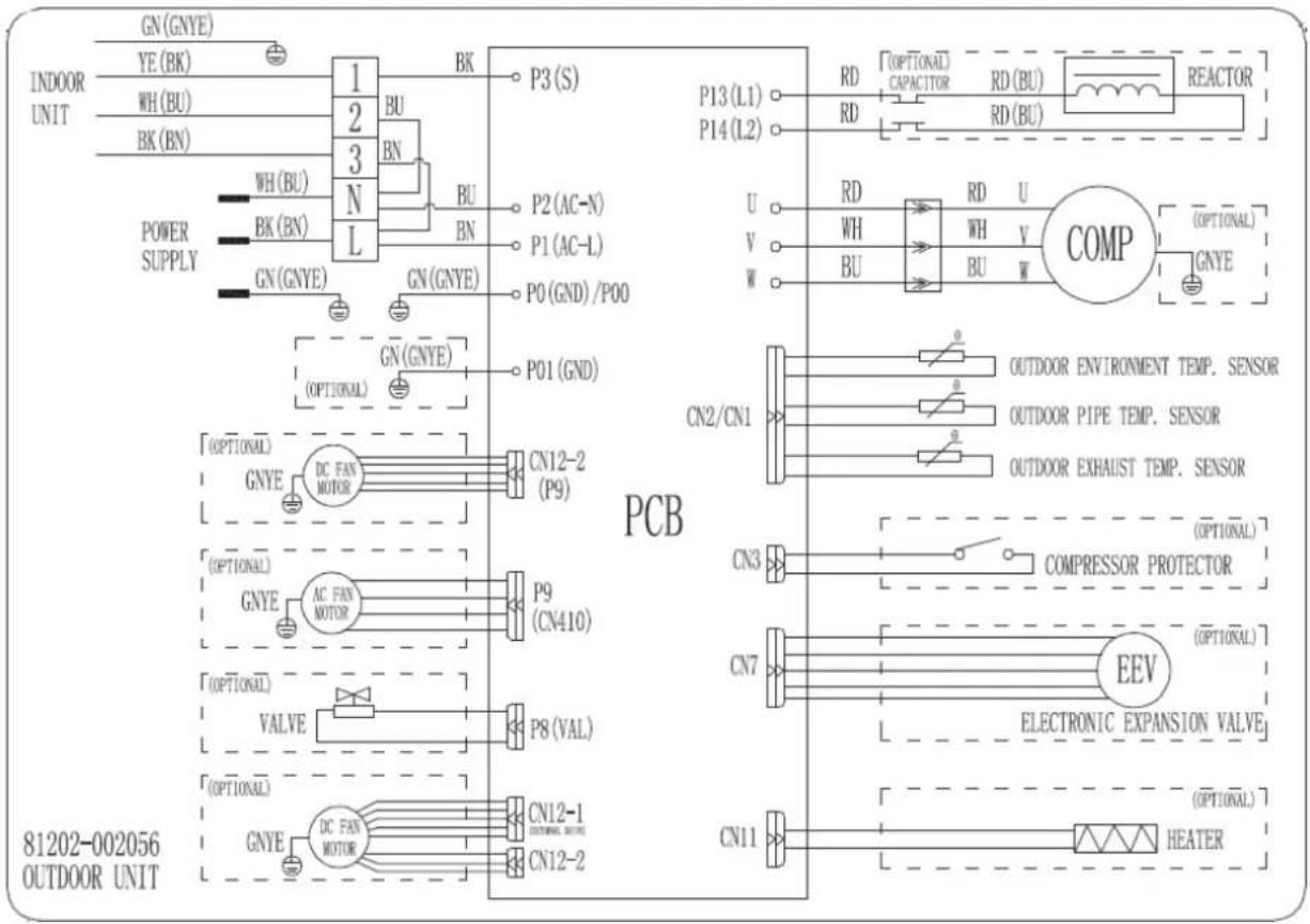
INDOOR MODEL: DXTC12E426-20
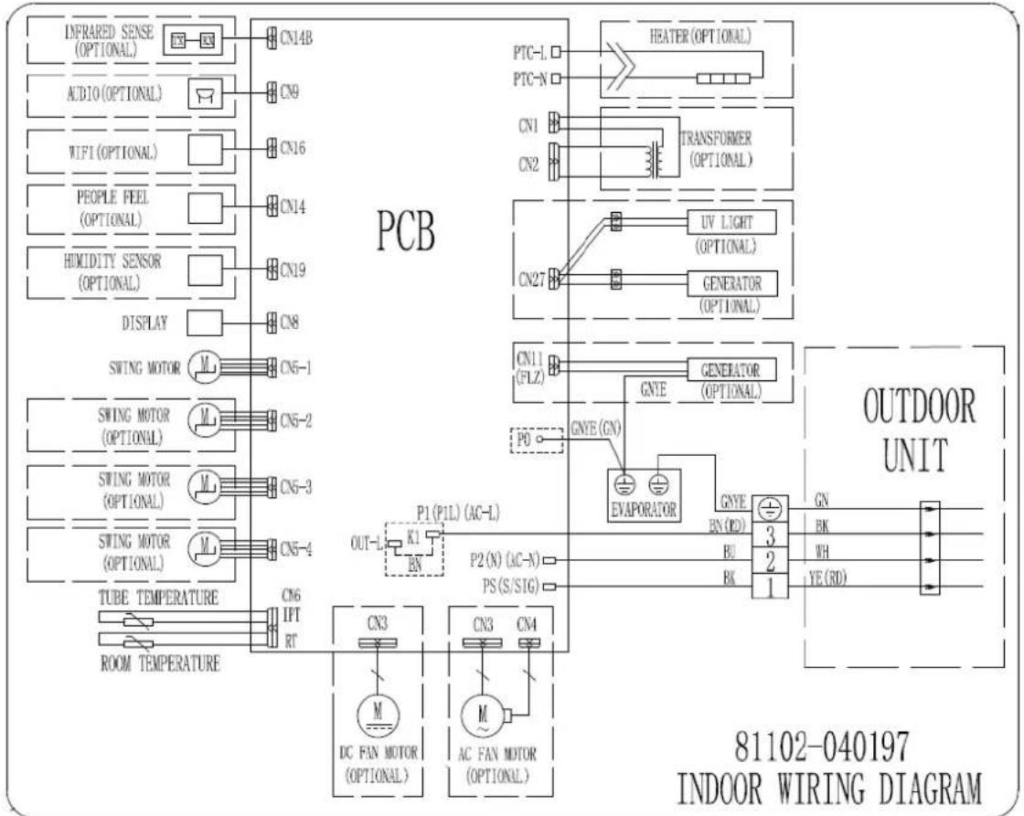
flowchart
graph TD
    subgraph PCB
        A["INFRARED SENSE (OPTIONAL)"] --> B["CN14B"]
        C["AUDIO (OPTIONAL)"] --> D["CN9"]
        E["WIFI (OPTIONAL)"] --> F["CN16"]
        G["PEOPLE FEEL (OPTIONAL)"] --> H["CN14"]
        I["HUMIDITY SENSOR (OPTIONAL)"] --> J["CN19"]
        K["DISPLAY"] --> L["CN8"]
        M["SWING MOTOR"] --> N["CN5-1"]
        O["SWING MOTOR (OPTIONAL)"] --> P["CN5-2"]
        Q["SWING MOTOR (OPTIONAL)"] --> R["CN5-3"]
        S["SWING MOTOR (OPTIONAL)"] --> T["CN5-4"]
        U["TUBE TEMPERATURE"] --> V["CN6 IPT RT"]
        W["ROOM TEMPERATURE"] --> X["CN3 DC FAN MOTOR (OPTIONAL)"]
    end

    subgraph OUTDOOR UNIT
        Y["HEATER (OPTIONAL)"] --> Z["CN1"]
        AA["TRANSFORMER (OPTIONAL)"] --> AB["CN2"]
        AC["UV LIGHT (OPTIONAL)"] --> AD["CN27"]
        AE["GENERATOR (OPTIONAL)"] --> AF["CN11 (FLZ)"]
        AG["GENERATOR (OPTIONAL)"] --> AH["GNE"]
        AI["GNE (CN)"] --> AJ["EVAPORATOR"]
        AK["GNEY"] --> AL["BN (RD)"]
        AM["BU"] --> AN["BK"]
        AO["3"] --> AP["GN"]
        AQ["2"] --> AR["BK"]
        AS["YE (RD)"] --> AT["1"]
    end

    style PCB fill:#f9f,stroke:#333
    style OUTDOOR UNIT fill:#ccf,stroke:#333
    style PCB fill:#cfc,stroke:#333
    style OutdoorUNIT fill:#fcc,stroke:#333
OUTDOOR MODEL: DXTC12C426-20
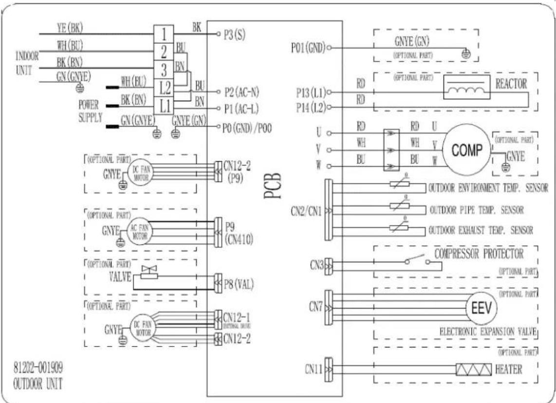
INDOOR MODEL: DXTC18E426A-20
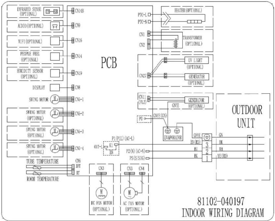
flowchart
graph TD
    subgraph PCB
        A["INFRARED SENSE (OPTIONAL)"] --> B["CN14B"]
        C["ACIO (OPTIONAL)"] --> D["CN9"]
        E["WIFI (OPTIONAL)"] --> F["CN16"]
        G["PEOPLE FEEL (OPTIONAL)"] --> H["CN14"]
        I["HIMIDITY SENSOR (OPTIONAL)"] --> J["CN19"]
        K["DISPLAY"] --> L["CN8"]
        M["SWING MOTOR"] --> N["M"]
        O["SWING MOTOR (OPTIONAL)"] --> P["M"]
        Q["SWING MOTOR (OPTIONAL)"] --> R["M"]
        S["SWING MOTOR (OPTIONAL)"] --> T["M"]
        U["TUBE TEMPERATURE"] --> V["CN6 IPT RT"]
        W["ROOM TEMPERATURE"] --> X["CN3"]
        Y["DC FAN MOTOR (OPTIONAL)"] --> Z["M"]
        AA["AC FAN MOTOR (OPTIONAL)"] --> AB["M"]
    end

    subgraph Outdoor Unit
        AC["HEATER (OPTIONAL)"] --> AD["PTC-L"]
        AE["TRANSFORMER (OPTIONAL)"] --> AF["PTC-N"]
        AG["UV LIGHT (OPTIONAL)"] --> AH["CN1"]
        AI["GENERATOR (OPTIONAL)"] --> AJ["CN2"]
        AK["GNTE GENERATOR (OPTIONAL)"] --> AL["CN27"]
        AM["GNYE (GN)"] --> AN["P0"]
        AO["EVAPORATOR"] --> AP["GNYE BN (RD)"]
        AQ["BU BK"] --> AR["3 2 1"]
        AS["YE (RD)"] --> AT["GN BK WH YE (RD)"]
    end

    style PCB fill:#f9f,stroke:#333
    style Outdoor Unit fill:#ccf,stroke:#333
    style PCB fill:#cfc,stroke:#333
    style Outdoor Unit fill:#fcc,stroke:#333
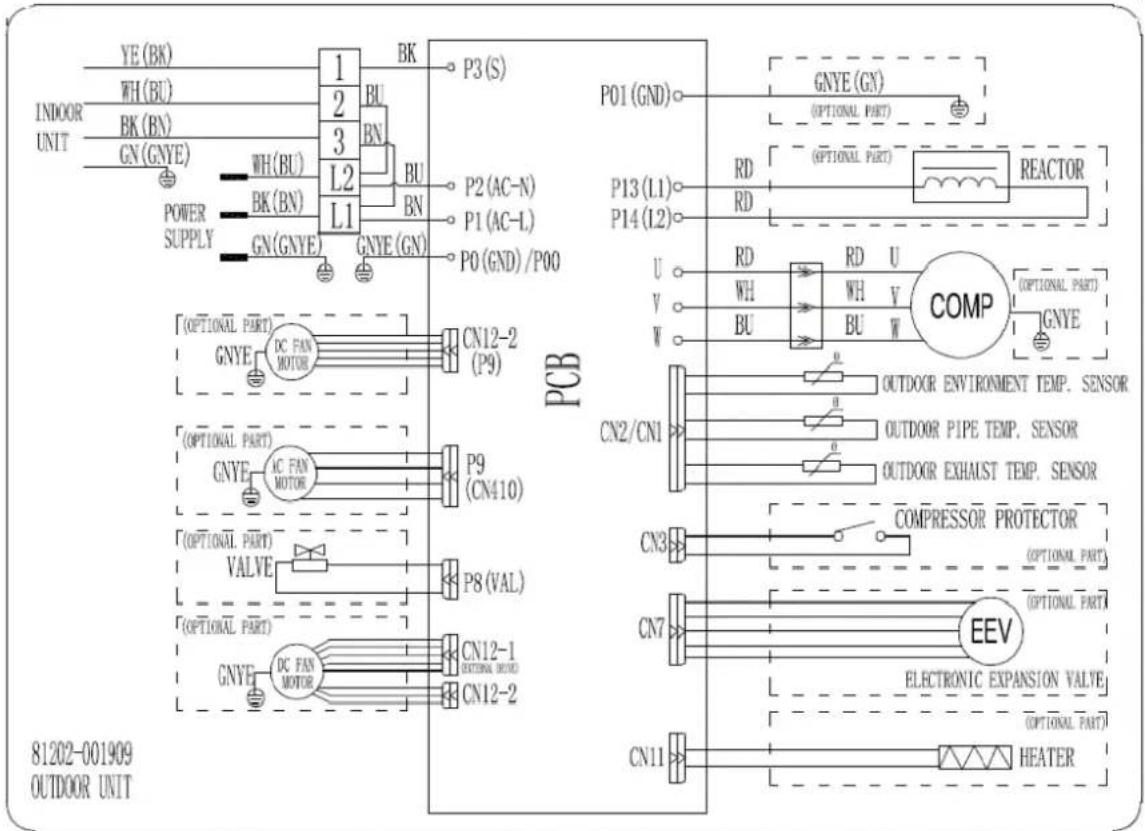
OUTDOOR MODEL: DXTC18C426A-20
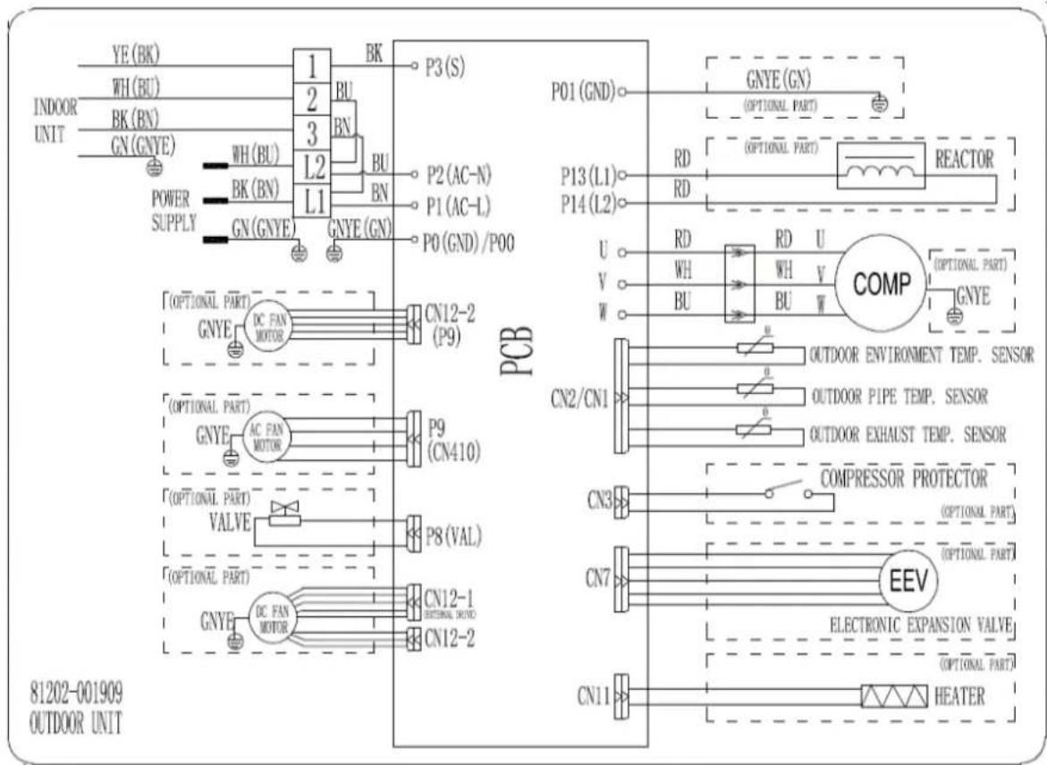
![YE (BK) WH (BU) INDOOR UNIT BK (BN) GN (GNYE) WH (BU) POWER SUPPLY BK (BN) GN (GNYE) 1 2 3 L2 L1 BK BU LN P3 (S) P2 (AC-N) P1 (AC-L) P0 (GND) / P00 PCB P01 (GND) GNYE (GN) (OPTIONAL PART) P13 (L1) RD RD REACTOR U VD VW RD RD U WH WH V BU W COMP (OPTIONAL PART) OUTDOOR ENVIRONMENT TEMP. SENSOR CN2/CN1 OUTDOOR PIPE TEMP. SENSOR OUTDOOR EXHAUST TEMP. SENSOR CN3 COMPRESSOR PROTECTOR (OPTIONAL PART) CN7 EEV ELECTRONIC EXPANSION VALVE (OPTIONAL PART) CN11 HEATER [OPTIONAL PART] GNYE DC FAN MOTOR CN12-2 (P9) [OPTIONAL PART] GNYE AC FAN MOTOR P9 (CN410) [OPTIONAL PART] VALVE P8 (VAL) [OPTIONAL PART] GNYE DC FAN MOTOR CN12-1 OPTIONAL MODE CN12-2 81202-001909 OUTDOOR UNIT](/content/2026/05/955994/images/6e666c92693de76ce10970b509f578f7744b0b530e56b7129ca50354975a4c11.jpg)
INDOOR MODEL: DXTC24E426A-20
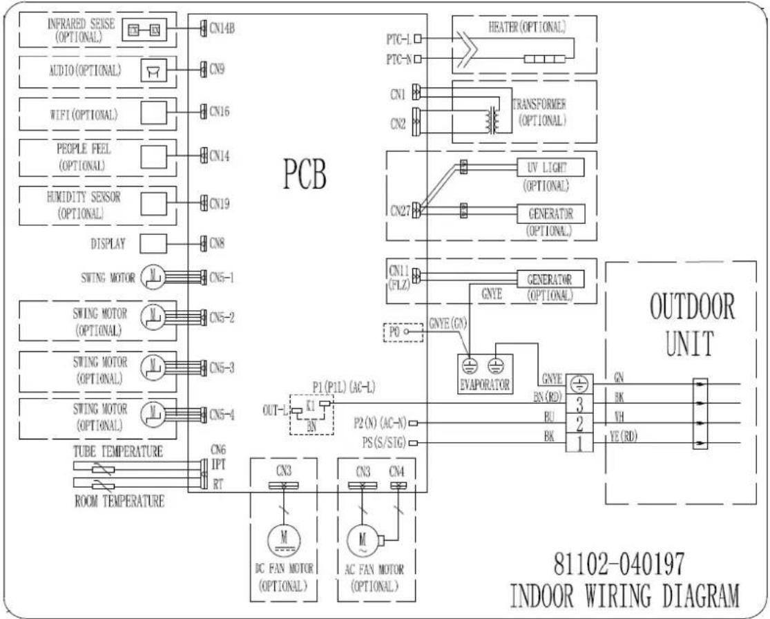
flowchart
graph TD
    subgraph PCB
        A["INFRARED SENSE (OPTIONAL)"] --> B["CN14B"]
        C["AUDIO (OPTIONAL)"] --> D["CN9"]
        E["WIFI (OPTIONAL)"] --> F["CN16"]
        G["PEOPLE FEEL (OPTIONAL)"] --> H["CN14"]
        I["HUMIDITY SENSOR (OPTIONAL)"] --> J["CN19"]
        K["DISPLAY"] --> L["CN8"]
        M["SWING MOTOR"] --> N["CN5-1"]
        O["SWING MOTOR (OPTIONAL)"] --> P["CN5-2"]
        Q["SWING MOTOR (OPTIONAL)"] --> R["CN5-3"]
        S["SWING MOTOR (OPTIONAL)"] --> T["CN5-4"]
        U["TUBE TEMPERATURE"] --> V["CN6 IPT RT"]
        W["ROOM TEMPERATURE"] --> X["CN3"]
        Y["DC FAN MOTOR (OPTIONAL)"] --> Z["CN3 CN4"]
        AA["AC FAN MOTOR (OPTIONAL)"] --> AB["M"]
        AC["P0"] --> AD["GNYE (GN)"]
        AE["P1 (P1L) (AC-L)"] --> AF["K1 BN"]
        AG["P2 (N) (AC-N)"] --> AH["PS(S/STG)"]
        AI["EVAPORATOR"] --> AJ["GNYE BN(RD)"]
        AK["GENERATOR (OPTIONAL)"] --> AL["UV LIGHT (OPTIONAL)"]
        AM["TRANSFORMER (OPTIONAL)"] --> AN["CN1"]
        AO["PTC-L"] --> AP["HEATER (OPTIONAL)"]
        AQ["PTC-N"] --> AR["Transformer (OPTIONAL)"]
        AS["CN2"] --> AT["CON2"]
        AU["CN27"] --> AV["UV LIGHT (OPTIONAL)"]
        AW["GENERATOR (OPTIONAL)"] --> AX["CON11 (FLZ)"]
        AY["PO"] --> AZ["GNYE (GN)"]
        BA["OUTDOOR UNIT"] --> BB["GN BK VH YE(RD)"]
    end
    style PCB fill:#f9f,stroke:#333
    style OutdoorUnit fill:#ccf,stroke:#333
    style IndoorSensors fill:#cfc,stroke:#333
OUTDOOR MODEL: DXTC24C426A-20
INDOOR MODEL: DXTC36E426A-17
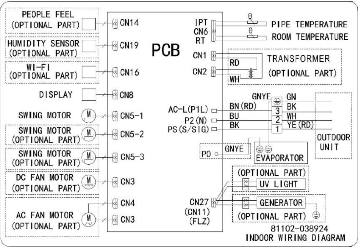
flowchart
graph TD
    A["PEOPLE FEEL (OPTIONAL PART)"] --> B["CN14"]
    C["HUMIDITY SENSOR (OPTIONAL PART)"] --> D["CN19"]
    E["WI-FI (OPTIONAL PART)"] --> F["CN16"]
    G["DISPLAY"] --> H["CN8"]
    I["SWING MOTOR"] --> J["M"]
    K["SWING MOTOR (OPTIONAL PART)"] --> L["M"]
    M["SWING MOTOR (OPTIONAL PART)"] --> N["M"]
    O["DC FAN MOTOR (OPTIONAL PART)"] --> P["M"]
    Q["AC FAN MOTOR (OPTIONAL PART)"] --> R["M"]
    B --> S["PIPE TEMPERATURE ROOM TEMPERATURE"]
    D --> T["TRANSFORMER (OPTIONAL PART)"]
    F --> T
    H --> U["AC-L(P1L)"]
    H --> V["P2(N)"]
    H --> W["PS(S/SIG)"]
    U --> X["GNYE"]
    V --> Y["BN(RD)"]
    V --> Z["BU"]
    V --> AA["BK"]
    W --> AB["GNYE"]
    W --> AC["EVAPORATOR"]
    X --> AD["OUTDOOR UNIT"]
    Y --> AE["(OPTIONAL PART)"]
    Z --> AF["UV LIGHT"]
    AA --> AG["GENERATOR"]
    AB --> AH["81102-038924 INDOOR WIRING DIAGRAM"]
OUTDOOR MODEL: DXTC36C426A-17
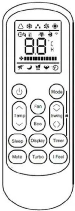
3.2 Remote Controller
REMOTE CONTROL
Remote control DISPLAY
| No. | Symbols | Meaning |
| 1 | Auto Mode | |
| 2 | Cooling Mode | |
| 3 | Dry Mode | |
| 4 | Fan only Mode | |
| 5 | Heating Mode | |
| 6 | ECO Mode | |
| 7 | Timer | |
| 8 | Temperature indicator | |
| 9 | Fan speed:Auto/ low/mid/ high | |
| 10 | Mute function | |
| 11 | TURBO function | |
| 12 | Up-down auto swing | |
| 13 | Left-right auto swing | |
| 14 | SLEEP function | |
| 15 | I FEEL function | |
| 16 | Signal indicator | |
| 17 | Child-Lock |
4. Electronic Controller Introduction
4.1 Electronic Controller
RT----Room Temperature.
IPT----Indoor Pipe (Coil) Temperature.
ST----Indoor Setting Temperature.
OPT---Outdoor Pipe Temperature.
OAT---Outdoor Ambient Temperature.
ODT---Outdoor Discharge Temperature.
CRT---Compensated Room Temperature.
IDU--- Indoor unit
ODU---Outdoor unit.
Note: When AC finishing installation, because of the air ventilation and the distance of temperature test sensor to different location of the house, the temperature for IDU PCB control need compensation.
-
Cooling mode. CRT=RT;
-
Heating mode. CRT=RT-3°C----Split AC.
4.1.1 Auto mode
-
The set temperature can be adjusted from 16-31°C on auto mode, the operation of fan speed and vane position according to preset.
-
Operation
When unit set to auto mode, it will work on cooling, heating or fan mode totally according to t --the temperature difference between RT and ST shown as table:
| Mode Δt=RT-ST | |
| COOLING | Δt >1°C |
| FAN | -1°C≤Δt≤ 1°C |
| HEATING | Δt<-1°C |
4.1.2 Cooling mode
- Temperature control :16-31°C, and the operation of fan speed and vane position according to preset.
2. Compressor and process control
1). When RT-ST≥0.5°C, the compressor starts up working, AC operates as customer preset;
2). When
a. RT-ST≤-3°C and compressor keeps 2 min continuously; or
b. RT-ST≤-2°C and compressor works in lowest frequency for 5 min continuously; or
c. RT-ST≤-1°C and compressor works in lowest frequency for 10 min continuously,
The compressor stops operation.
3). The compressor frequency control: Based on relation of RT & ST, and the changing speed of RT.
4). The compressor will also stop working while unit:
a. switched off.
b. under protection.
c. changed to fan mode.
5). Under normal operation, the compressor can be stopped by program only working after 7 min once it starts up.
6). In the process of unit operation, once the compressor ceased, it should be 3 min delay for the next procedure.
3. ODU Fan motor control:
1). While unit:
a. switched off.
b. under protection.
c. to the set temperature.
After compressor ceased, the fan motor stops working according to the temperature of OPT and OAT, the max delay for the motor should be less than 160s.
2). When switch on unit on cooling mode, ODU fan motor will delay 5s after compressor starts up.
- When ODU failure or stops for protection, IDU works as preset.
5. Anti-frosting protection
Control the unit operation frequency and the frequency changing rate to achieve anti-frosting protection.
1). Frequency Slowly Increasing(FSI):
a. If 6^ ≤ IPT < 7^ , the frequency increasing rate is 1Hz/60s, slowly increasing operation speed.
b. When IPT≥7°C, unit quit from protection.
2). Frequency Limitation:
If 5^ ≤ IPT < 6^ , the compressor frequency forbidden to increase
3). Normal Frequency Decreasing (NFD):
If 3^ ≤ IPT < 4^ , the frequency decreasing rate is 8Hz/90s, until to the lower frequency limit.
4). Fast Frequency Decreasing (FFD):
If 2^ ≤ IPT < 3^ , the frequency decreasing rate is 16Hz/90s , until to the lower frequency limit.
5). Unit stop:
a. When IPT<1°C for 3min continuously, unit stops working for anti-defrosting protection.
b. While IPT>6°C, and the unit stopped for 3 min already, can the unit recover to operation.
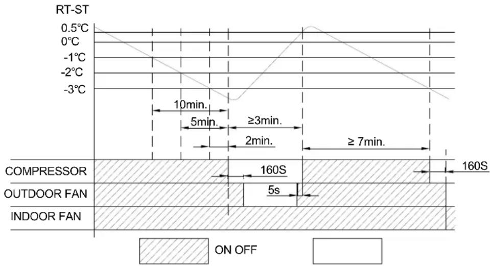
line
| Time Period | Temperature (°C) | |-------------|------------------| | 10min | -3 | | 5min | -2 | | ≥3min | -1 | | 2min | 0 | | ≥7min | 1 | | 160S | 2 | | 160S | 5 | | ON OFF | 0.5 |4.1.3 Dry mode
- Temperature control: 16\~31°C.
Fan speed: low
Vane blade position: as customer preset
- When ODU failure or stops for protection, IDU works as preset.
- Failure protection: as cooling mode.
- Energy saving and sleep mode: Invalid.
4.1.4 Heating mode
- Temperature control: 16-31°C.
2. Compressor and process control.
1). When ST-CRT≥0.5°C, the compressor starts up working, AC operates as customer preset;;
2). When
a. ST-CRT≤-3°C and compressor keeps 2 min continuously; or
b. ST-CRT≤-2°C and compressor works in lowest frequency for 5 min continuously; or
c. RT-CRT≤-1°C and compressor works in lowest frequency for 10 min continuously,
The compressor stops operation.
3). The compressor frequency control: Based on relation of RT & ST, and the changing speed of RT.
4). The compressor will also stop working while unit:
a. switched off.
b. under protection.
c. changed to fan mode.
5). Under normal operation, the compressor can be stopped by program only working after 7 min once it starts up.
6). In the process of unit operation, once the compressor ceased, it should be 3 min delay for the next procedure.
- IDU time delay: When compressor stops or unit switches off while in heating mode, IDU fan motor will work for a few seconds more to prevent overheat.
4: ODU Fan motor control:
1). While unit:
a. To be switched off
b. Under protection.
c. To the set temperature
After compressor ceased, the fan motor stops working according to the temperature of OPT and OAT, the max delay for the motor should be less than 160s.
2). When switch on unit on heating mode, ODU fan motor will delay 5s after compressor starts up
3). in the process of defrosting, the fan motor will stop operation 48s delay after compressor stopped.
4). defrosting finish, the compressor stops operation, the fan motor will start working simultaneously.
5. 4-way valve control
1). On Cooling/Dry/Fan mode, 4-way valve: OFF, when unit switched on heating mode, 4-way valve: ON.
2). When heating mode switched off, or changed from heating to other modes, the 4-way valve will be OFF 2 min delay after the compressor stops working.
3). Unit stops working caused by any kind of protection, the 4-way valve will be OFF 4 min delay.
4). In the process of defrosting, 4-way valve will be OFF 43s delay after compressor stopped.
5). When defrosting finish, the compressor stops operation, 4-way valve will be ON after 43s delay.
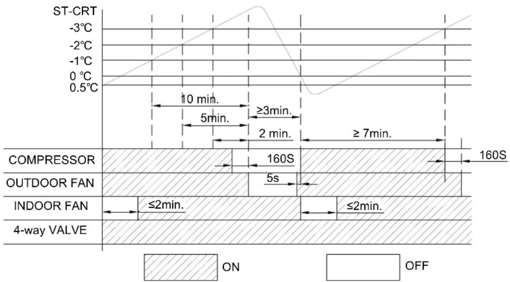
other
| Time Interval | Label | Value | | ------------- | ------------- | --------- | | 10 min. | COMPRESSOR | 160S | | 2 min. | OUTDOOR FAN | 5s | | ≥3 min. | COMPRESSOR | 160S | | ≥7 min. | OUTDOOR FAN | 160S | | ≤2 min. | INDOOR FAN | ≤2min. | | ≤2 min. | 4-way VALVE | ≤2min. |6. Defrost
Note: t1: compressor continuous works time.
t2: AC unit operation first time going to defrost circle.
t3: compressor accumulated working time (when OPT ≤ 3^ unit starts to count the time for t3).
When AC unit working to:
t1≥t2, or
t3≤t1<t2.
and also the temperature (related to OAT & OPT) tested 3 min continuously meets for defrosting.
Defrosting start up: Compressor stops working, and re-starts to working after 50s delay;
Conditions for quitting defrosting
After defrosting 60s, and OAT≥12°C; or
OAT < -5^ , and OPT ≥ 8^ for 80s continuously; or
The defrosting for 10 min.
When AC meet any of condition a, b or c, defrosting finish.
| COMPRESSOR | 50S | 50S | |||
| 4-way VALVE | 43S | 43s | |||
| OUTDOOR FAN | 48S | Defrosting max time | |||
ON
OFF
Defrosting end off: Compressor stops working, and re-starts to working after 50s delay;
7. Cold air prevention:
This function intends to prevent cold air from being discharged when the heating operation starts up
1). IDU fan motor cold air prevention
.When RT<24°C:
a. If ITP>31°C while compressor works for 5 min, fan motor will work according to preset fan speed.
b. If IPT≤31°C, fan motor stops working while compressor operation within 2min, if IPT≥27°C, fan motor works in low speed 2 min, then change to preset speed.
When RT≥24°C:
a. Within 2 min after compressor start up working, once IPT>27°C, fan motor will change to preset speed.
b. After compressor starts working 2 min, fan motor change to preset speed directly.
2). Vane blade operation for cold air prevention.
If the vane works on status of non-swing: While IPT increase to a special degree, the vane blade will change the position to:
Default angle; or
Previous position; or
Customer preset.
The above operation can work one time only, when compressor stops working, the unit will once again inspect the function. If the vane works on swing: When IDU quits from cold air prevention, vane operate as preset.
8. "8°C" Heating
When function effective, it will make sure the room temperature not lower than 8^ C, unit works on heating mode.
4.1.5 Fan mode
- The temperature setting: 16\~31°C,
Fan speed and vane position: as preset. The function for remote controller 58E only. - For above function, when unit preset to be auto fan mode, the fan motor will change its operation speed based on the temperature difference of ambient and preset temperature.
- ODU always OFF.

line
| Fan Condition | Temperature Change (°C) | | :--- | :--- | | High fan | 2 | | Mid fan | 0 | | Low fan | -4 | | 4°C | 4 | | 2°C | 0 | δt comes down; δt goes up4.1.6 Timer
The unit has times control, when the unit meet the timer preset, it will be switched on or off automatically.
TIMER ON
1). TIMER ON can be set only when the air conditioner is OFF.
2). Press TIMER on the remote control ONCE to enter time setting.
3). Press "▲" or "▼" to set the time for unit to start working.
4). Set other function as MODE, FAN SPEED, SWING etc.
5). Press TIMER ONCE AGAIN to confirm the TIME ON setting
TIMER OFF
1). TIMER OFF can be set only when the air conditioner is ON.
2). Press TIMER on the remote control ONCE to enter time setting.
3). Press "▲" or "▼" to set the time for unit to stop working.
4). Press TIMER ONCE AGAIN to confirm the TIME OFF setting
Note: In case of no selection for the time setting within 10s, the timer function will be OFF automatically.
4.1.7 Sleeping mode
While AC works in sleeping mode, the light of POWER SUPPLY and SLEEP always ON, and the temperature display will be OFF after 15s.
In this mode, the AC unit works according to the SLEEP CURVE as designed.
Sleeping mode the unit can work 10 hours continuously, after that it will quit from this mode and work as previous presetting.
4.1.8 Emergency switch
When the EMERGENCY switch is pressed one time, COOLING mode is selected and if it pressed again within 3s, HEATING mode selected, while press once again, the unit will be switched off.
When the remote controller out of function, batteries lost power, for example, the EMERGENCY button in the front of indoor unit can be used for function test.
NOTE: Do not press the EMERGEMCY switch during normal operation.
4.1.9 Auto-restart function
While air conditioner is operating in one mode, all of its operation data, such as working mode, preset temperature etc. would be memorized into IC by main PCB. If power supply cut off due to reasons and recover again, the AUTO-RESTART function will set synchronously and the air conditioner would work at the same mode as before.
Note: The function setting:
Within 3 min while power on unit, set the unit on cooling mode, set temperature 30^ C, and mid fan speed, press the ECO button 10 times within 8s, the AUTO-RESTART will be activated.
4.1.10 Protection
4.1.10.1 Overload protection
1. Overload protection for Cooling or Dry mode
1). if:
a. OPT≥62°C, unit stops working for overload protection.
b. OPT<55°C, after compressor stopped for 3 min, can the unit be started to operate.
2). When OPT ≥ 55^ , the compressor will be frequency limited/reduced for over load protection.
3). If unit have 6 times of over load stop-working protection continuously, this protection can't be recovered unless press ON/OFF button, and unit will show failure code.
In the process of operation, once the compressor runs continuously more than 6 min, the counter of over load stop-working protection will be reset to zero and start a new counting process.
The failure and times for protection will eliminate immediately once the unit to be switched off, on fan mode or changed to be heating mode from others.
Note: If the defective failure can't be recovered, the failure can't eliminate even if operation mode changed.
2. Overload protection for Heating mode
1). If:
a. IPT≥62°C, unit stops working for overload protection.
b. IPT<55°C, after compressor stopped for 3 min, can the unit be started to operate.
2). When IPT≥55°C, the compressor will be frequency limited/reduced for over load protection.
3). If unit have 6 times of over load stop-working protection continuously, this protection can't be recovered unless press ON/OFF button, and unit will show failure code.
In the process of operation, once the compressor runs continuously more than 6 min, the counter of over load stop-working protection will be reset to zero and start a new counting process.
The failure and times for protection will eliminate immediately once the unit to be switched off, on fan mode or changed to be heating mode from others.
Note: If the defective failure can't be recovered, the failure can't eliminate even if operation mode changed.
4.1.10.2 The compressor discharge temperature protection
- If ODT≥115°C, unit stops working for over temperature protection;
While ODT<100°C, & after compressor stopped for 3 min, the unit can be started to operate.
- If ODT≥100°C, the compressor will be frequency limited/reduced for over temperature protection.
- If unit have 6 times of discharge over temperature stop working protection continuously, this protection can't be recovered unless press ON/OFF button, and unit will show failure code.
In the process of operation, once the compressor runs continuously more than 6 min, the counter of discharge over temperature stop working protection will be reset to zero and start a new counting process.
The failure and times for protection will eliminate immediately once the unit to be switched off, or changed to fan mode.
Note: If the defective failure can't be recovered, the failure can't eliminate even if operation mode changed.
4.1.10.3 The current protection
- If the unit A/C working current more than Limited current ( L_c ), the compressor will be frequency limited / reduced for over current protection.
- When unit A/C working current more than Stopped current ( I_sc ), AC unit stops working. Only when the compressor stops for 3 min can the unit be recovered operation.
- If unit have 6 times of over current stop-working protection continuously, this protection can't be recovered unless press ON/OFF button.
In the process of unit operation, once the compressor runs continuously more than 6 min, the counter of stop-working protection will be reset to zero and re-start a new counting process.
Note: For different models, lc and lsc have different programmed value.
4.1.10.4 IPM overheating protection
- When IPM temperature T_IPM ≥ 87^ , the compressor will be frequency limited / reduced for IPM over temperature protection.
- When T_IPM ≥ 95^ , the AC unit stops working for AC system protection.
If T_IPM<87^ , and after compressor stopped for 3 min, can the unit be started to operate.
- If unit have 6 times of IPM over temperature stop working protection continuously, this protection can't be recovered unless press ON/OFF button, and unit will show failure code.
In the process of operation, once the compressor runs continuously more than 6 min, the counter of over load stop working protection will be reset to zero and re-start a new counting process.
The failure and times for protection will eliminate immediately once the unit to be switched off, or changed to fan mode.
Note: If the defective failure can't be recovered, the failure can't eliminate even if operation mode changed.
4.1.11 Complementary
4.1.11.1 Energy saving (ECO)
Function effective on Cooling and Heating mode only.
On cooling mode, the set temperature range from 26°C to 31°C, on heating mode, from 16°C to 25°C.
4.1.11.2 TURBO
Function effective on Cooling, Heating, Fan and Auto modes, and fan speed operates on highest.
4.1.11.3 The communication control
If ODU PCB can't get signal feedback from IDU for 2 min continuously, AC unit stops working and shows E0 error code as IDU/ODU communication failure.
Once the IDU & ODU communication recovery, and also the compressor stopped for 3 min already, can the unit be recovered to operate.
4.2.2 Download and installation
Customer can scan the QR in the user manual or from appliance APP store to download the APP and install it in the cell phone, while installation achieved, there would be an icon as picture created on the desktop. Register the account and add the device to system, customer can control the air conditioner by internet or LAN.
TUYA APP


natural_image
Purple square icon with a white house symbol and the text 'Smart Life' below it (no additional text or symbols)GUBEI APP


Intelligence AC
PART II Installation and Maintenance
1. Notes for installation and maintenance Safety Precautions
Important!
Please read the safety of precautions carefully before installation and maintenance. The following contents are very important for installation and maintenance. Please follow the instructions bellow.
● The installation or maintenance must accord with the instructions.
● Comply with all national electrical codes and local electrical codes.
● Pay attention to the warnings and cautions in this manual.
● All installation and maintenance shall be performed by distributor or qualified person.
- All electric work must be performed by licensed technician according to local regulations and instructions given in this manual.
- Be caution during installation and maintenance. Prohibit incorrect operation to prevent electric shock, casualty and other accidents.
Warnings
Electrical safety Precautions.
1) Cut off the power supply of air conditioner before checking and maintenance.
2) The air conditioner must apply specialized circuit and prohibit share the same circuit with other appliances.
3) The air conditioner should be installed in suitable location and ensure the power plug is touchable.
4) Make sure each wiring terminal is connected firmly during installation and maintenance.
5) Have the unit adequately grounded. The grounding wire can't be used for other purposes.
6) Must apply protective accessories such as protective boards, cable-cross loop and wire clip.
7) The live wire, neutral wire and grounding wire of power supply must be corresponding to the live wire, neutral wire and grounding wire of the air conditioner.
8) The power cord and power connection wires can't be pressed by hard objects.
9) If power cord or connection wire is broken, it must be replaced by qualified person.
10) If the power cord or connection wire is not long enough, please get the specialized power cord or connection wire from the manufacture or distributor. Prohibit prolong the wire by yourself.
11) For the air conditioner without plug, an air switch must be installed in the circuit. The air switch should be all-pole parting and the contact parting distance should be more then 3mm.
12) Make sure all wires and pipes are connected properly and the valves are opened before energizing.
13) Check if there is electric leakage on the unit body. If yes, please eliminate the electric leakage.
14) Replace the fuse with a new one of the same specification if it is burnt down, don't replace it with a cooper wire or conducting wire.
15) If the unit is to be installed in a humid place, the circuit breaker must be installed.
Installation Safety Precaution
1) Select the installation location according to the requirement of this manual. (See the requirements in installation part).
2) Handle unit transportation with care, the unit should not be carried by only one person if it is more than 20kg.
3) When installing the indoor unit and outdoor unit, a sufficient fixing bolt must be installed, make sure the installation supporter is firm.
4) Ware safety belt if the height of working is above 2m.
5) Use equipped components or appointed components during installation.
6) Make sure no foreign objects are left in the unit after finishing installation.
Improper installation may lead to fire hazard, explosion, electric shock or injury.
Safety precautions for Installing and Relocating the unit.
To ensure safety, please be mindful of the following precautions.

Warnings
When installing or relocating the unit, be sure to keep the refrigerant circuit free from air or substances other than the specified refrigerant.
Any presence of air or other foreign substance in the refrigerant circuit will cause system pressure rise or compressor rupture, resulting in injury.
When installing or moving this unit, do not charge the refrigerant which is not comply with that on the nameplate or unqualified refrigerant.
Otherwise, it may cause abnormal operation, wrong action, mechanical malfunction or even series safety accident. When refrigerant needs to be recovered during relocating or repairing the unit, be sure that the unit is running in cooling mode. Then, fully close the valve at high pressure side (two-way valve). About 30-40 seconds later, fully close the valve at low pressure side (3-way valve), immediately stop the unit and disconnect power. Please note that the time for refrigerant recover should not exceed 1 minute.
If refrigerant recovery takes too much time, may be cause compressor overheat, resulting in injury.
During refrigerant recovery, make sure that two-way valve and 3-way valve are fully closed and power is disconnected before detaching the connecting pipe.
If compressor starts running when the valves is open and connecting pipe is not yet connected, air will be sucked in and cause pressure rise and then compressor overheat or gas leak, resulting in injury.
When installing the unit, make sure that connecting pipe is securely connected before the compressor starts running. If compressor starts running when the valves is open and connecting pipe is not yet connected, air will be sucked in and cause pressure rise and then compressor overheat or gas leak, resulting in injury.
Prohibit installing the unit at the place where there may be leaked corrosive gas or flammable gas.
If there leaked gas around the unit, it may cause explosion and other accidents.
Do not use extension cords for electrical connections. If the electric wire is not long enough, please contact a local service center authorized and ask for a proper electric wire.
Poor connection may lead to electric shock or fire.
Use the specified types of wires for electrical connections between the indoor and outdoor units. Firmly clamp the wires so that their terminals receive no external stresses.
Electric wires with insufficient capacity, wrong wire connections and insecure wire terminals may cause electric shock or fire.
Introduction R32, R290 air conditioner installation
1) Introduction to Refrigerants R32 & R290
The refrigerants used for air conditioners are environmentally friendly hydrocarbons R32 and R290. The two kinds of refrigerants are combustible and odorless. Moreover, they can burn and explode under certain condition. However, there will be no risk of burning and explosion if you comply with the following table to install your air conditioner in a room with an appropriate area and use it correctly.
Compared with ordinary refrigerants, Refrigerants R32 & R290 are environmentally friendly and do not destroy the ozone sphere and that their values of greenhouse effect are also very low.
2) R32/R290 air conditioner installation area requirement
$$ \mathrm{m} 1 = (4 \mathrm{m} ^ {3}) \times \text { L F L }, \mathrm{m} 2 = (2 6 \mathrm{m} ^ {3}) \times \text { L F L }, \mathrm{m} 3 = (1 3 0 \mathrm{m} ^ {3}) \times \text { L F L } $$
Where LFL is the lower flammable limit in kg/m ^3 , R290 LFL is 0.038kg/m ^3 , R32 LFL is 0.306kg/m ^3 .
For the appliances with a charge amount m1
The maximum charge in a room shall be in accordance with the flowing: M_=2.5×(LFL)^(5/4)× h_0× A^1/2
The required minimum floor area A_min to install an appliance with refrigerant charge M(kg) shall be in accordance with following: A_ = (M / (2.5 × (LFL)^(5/4) × h^0)) 2
Where:
M_max is the allowable maximum charge in a room, in kg;
M is the refrigerant charge amount in appliance, in kg;
A_min is the required minimum room area, in m2;
A is the room area, in m2;
LFL is the lower flammable limit, in kg/m3;
h0 is the installation height of the appliance, in meters for calculating M_max or A_min , 1.8 m for wall mounted;
Table GG.1 - Maximum charge (kg)
Category LFL(kg/m3) h0(m) Floor area (m2)Maximum charge (kg) 4 7 10 15 20 30 R290 0.038 0.6 0.05 0.07 0.08 0.1 0.1 1 0.18 1 0.08 0.11 0.03 0.06 0.09 0.2 1.8 0.15 0.2 0.24 0.29 0.34 0.41 2.2 0.18 0.24 0.29 0.36 0.41 0.51 0.65 R32 0.306 0.6 0.68 0.9 1.08 1.32 1.53 1.87 1 1.14 1.51 1.8 2.2 2.54 3.12 1.8 2.05 2.71 3.24 3.97 4.58 5.61 7.254 2.2 2.5 3.31 3.96 4.85 5.6 6.86 8.85
Table GG.2 - Minimum room area (m2)
Category LFL(kg/m3) h0(m) Charge amount (M) (kg)Minimum room area (m2) R290 0.038 0.152kg 0.228kg 0.304kg 0.456kg 0.608kg 0.76kg 0.988kg 0.6 / 82 146 328 584 912 1 / 30 53 118 210 328 555 1.8 / 9 16 36 65 101 171 2.2 / 6 11 24 43 68 115 R32 0.306 1.224kg 1.836kg 2.448kg 3.672kg 4.896kg 6.12kg 7.956kg 0.6 / 29 51 116 206 321 1 / 10 19 42 74 116 196 1.8 / 3 6 13 23 36 2.2 / 2 4 9 15 24 40
Caution:
- Please contact the nearest after-sale service center when maintenance is necessary. At the time of maintenance, the maintenance personnel must strictly comply with the Operation Manual provided by the corresponding manufacturer and any non-professional is prohibited to maintain the air conditioner.
- It is necessary to comply with the provisions of gas-related national laws and regulations.
- It is necessary to clear away the refrigerant in the system when maintaining or scrapping an air conditioner.
- When filling the combustible refrigerant, any of your rude operations may cause serious injury or injuries to human body or bodies and object or objects.
● A leak test must be done after the installation is completed.
- It is a must to do the safety inspection before maintaining or repairing an air conditioner using combustible refrigerant in order to ensure that the fire risk is reduced to minimum.
3) Installation Safety
Installation Safety Principles
Site Safety


Open Flames Prohibited
Ventilation Necessary
Operation Safety
Open Flames Prohibited


Mind Static Electricity Must wear protective clothing and anti-static gloves Don't use mobile phone Installation Safety
● Refrigerant Leak Detector
● Appropriate Installation Location

The left picture is the schematic diagram of a refrigerant leak detector.
Caution:
● The installation should be in a well-ventilated condition location.
- When you installing or maintaining an air conditioner using Refrigerant R32/R290, the location should be free fire from open or any other goods temperature higher than 370°C for R290/548°C for R32 which easily produces open fire include welding, smoking, drying oven.
- When installing an air conditioner of R32/R290, it is necessary to take appropriate anti-static measures such as wear anti-static clothing and gloves.
- It is necessary to choose the location for installation or maintenance where in the air inlets and outlets of the indoor and outdoor units should be not surrounded by obstacles or close to any heat source or combustible and/or explosive environment.
- If the indoor unit suffers refrigerant leak during the installation, it is necessary to immediately turn off the valve of the outdoor unit and all the personnel should go out till the refrigerant leaks completely for 15 minutes. If the product is damaged, it is a must to carry such damaged product back to the maintenance station and it is prohibited to weld the refrigerant pipe or conduct other operations on the user's site.
- It is necessary to choose the place where the inlet and outlet air of the indoor unit is even.
\- It is necessary to avoid the places where there are other electrical products, power switch plugs and sockets, kitchen cabinet, bed, sofa and other valuables right under the lines on two sides of the indoor unit.
Special tools:
Tool Name Requirement(s) for Use Mini Vacuum Pump It should be an explosion-proof vacuum pump; can ensure certain precision and its vacuum degree should be lower than 10Pa. Filling Device It should be a special explosion-proof filling device; have certain precision and its filling deviation should be less than 5g. Leak Detector It should be calibrated regularly; and its annual leak rate should not exceed 10g. Concentration Detector A) The maintenance site should be equipped with a fixed-type combustible refrigerant concentration detector and connected to a safeguard alarm system; its error must be not more than 5%.B) The installation site should be equipped with a portable combustible refrigerant concentration detector which can realize two-level audible and visual alarm; its error must be not more than 10%.C) The concentration detectors should be calibrated regularly.D) It is necessary to check and confirm the functions before using the concentration detectors. Pressure Gauge A) The pressure gauges should be calibrated regularly.B) The pressure gauge used for Refrigerant 22 can be used for Refrigerants R290 and R161; the pressure gauge used for R410A can be used for Refrigerant 32. Fire Extinguisher It is necessary to carry fire extinguisher(s) when installing and maintaining an air conditioner. On the maintenance site, there should be two or more kinds of dry powder, carbon dioxide and foam fire extinguishers and that such fire extinguishers should be placed at stipulated positions, with eye-catching labels and in handy places.
Maintenance
1). Inspections before maintenance.
(1) Inspection of maintenance environment
- There should be no leaked refrigerant in the room before operation.
- It is only allowed to operate in a room which meets the area requirement on the nameplate.
- It is necessary to make the room keep a continuous ventilation state at the time of maintenance.
- The room in the maintenance should be free from fire or welding, smoking, drying oven or any other goods temperature higher than 370°C (R290)/548°C (R32) which easily produces fire.
- During the maintenance, it is necessary to ensure that any person's any mobile phone or any electronic product with radiation in the room is powered off.
- The maintenance area should be equipped with a drying powder or carbon dioxide fire extinguisher and that such fire extinguisher can work.
(2) Inspection of maintenance equipment
- Check the maintenance equipment is applicable to the refrigerant or not and it is only allowed to use the professional equipment recommended by the air conditioner manufacturer.
- Check the refrigerant leak detector whether has been calibrated. The set maximum alarm concentration of the refrigerant leak detector should not exceed 25% of the lower explosion limit (LEL), the refrigerant leak detector must be working during maintenance.
2) Inspection of air conditioner
- It is necessary to ensure that the air conditioner is in reliable ground connection before maintenance.
- Make sure powered supply to air conditioner is off. Before maintenance, it is necessary to cut off the power and discharge the capacitor power which used in the air conditioner. If it is a must to need the power supply during the maintenance, it is necessary to do ongoing leak detection at the most dangerous position/point in order to avoid potential danger.
- Check the warning labels on the air conditioner whether are in good condition. It is necessary to replace the damaged or smeared warning labels.
3). Leak inspection before maintenance
Before maintenance, use the leak detector or concentration detector (pump-type) recommended by
the corresponding air conditioner manufacturer to check the air conditioner leak or not.
Warning
If leak may exist, it is necessary to move all the fire out from the site or extinguish fire and then immediately shut off the air conditioner. Meanwhile, it is necessary to make sure well-ventilated.
4). Safety principles during the maintenance
- At the time of maintenance, it is necessary to ensure well-ventilation on the site.
- It is prohibited to use fire including welding, smoking or other purposes. It is prohibited to use mobile phones.
- At the time of maintenance, if the relative humidity is lower than 40%, it is necessary to wear anti-static clothing and gloves.
\- If the combustible refrigerant is found leaking during the maintenance, it is a must to immediately take forced ventilation and plug up the leak source.
\- If the product is damaged to the extent that it is a must to open the refrigerating system for maintenance, it is a must to carry the product back to the maintenance station for maintenance. (It is prohibited to weld the refrigerant pipe and do other operations on the user's site.)
\- It is necessary to return the air conditioner to its initial state if it is necessary to provide visiting service again due to lacking spare part during the maintenance. Moreover, it is a must to ensure that the refrigerating system is in secure ground connection.
\- If it is necessary to provide visiting service with a refrigerant cylinder, the volume of refrigerant filled in such refrigerant cylinder should not exceed the stipulated value. When such cylinder is stored in a vehicle or placed on the installation or maintenance site, it is necessary to place it vertically and securely and keep it away from any place where there is any heat source, combustion source, radiation source or electrical equipment.
5). Requirements for the site of maintenance-station
● The maintenance location should be well-ventilated, with leveled ground and not in a basement.
- The maintenance should be divided into welding and non-welding areas both of which should be labeled clearly. There should be a certain safety distance between the two areas. The maintenance location should be equipped with ventilating and air-exhausting equipment to prevent the refrigerant gas from aggregating.
- It is necessary to provide some relevant instruments such as combustible refrigerant leak detector and have a leak detecting instrument management system. It is necessary to confirm that the leak detector can work normally before maintenance.
- The main power switch should be set outside the maintenance location and equipped with protective (explosion-proof) devices.
- It is necessary to provide firefighting devices such as dry powder or carbon dioxide fire extinguisher appropriate for extinguishing the electrical fire and keep such firefighting devices in a usable condition.
- Temporary wires and sockets are prohibited on the maintenance location.
6). Requirements for fill the refrigerants
- It is necessary to use nitrogen to clear the cyclic system before operating the refrigerating system and vacuumize the outdoor unit for 30 minutes at least.
- It is necessary to ensure that there is no cross contamination among different refrigerants when the refrigerant filling device is used. The total length including the refrigerant pipeline should be as short as possible in order to reduce the residual refrigerant inside such pipeline.
- It is necessary to vertically place the refrigerant storage tanks.
- It is necessary to ensure that the refrigerating system is in ground connection before the refrigerant is filled.
- When filling the refrigerant, it is necessary to fill corresponding type and volume of refrigerant as per the requirements on the product nameplate and overfilling is prohibited.
- It is necessary to seal the system in a safe sealing way after maintaining the refrigerating system.
- It is necessary to ensure that the maintenance will not damage or reduce the safety protection grade of the original system.
7). In-maintenance welding
- It is necessary to ensure that the maintenance location is well-ventilated.
- Before welding the outdoor unit, it is a must to confirm that the refrigerating system has been drained and the system has been cleaned and ensure that there has been no refrigerant in the outdoor unit.
- It is necessary to close the stop valve of the outdoor unit when using a welding gun to do the maintenance work such as cutting and welding.
8). Maintenance of electrical components
- It is necessary to use a special leak detector to check whether the maintained electrical parts location have the leak refrigerant.
- It is not allowed to refit, remove or cancel any component with the safety protection function after finishing the maintenance process.
- When maintaining the sealed parts, it is necessary to turn off the power of air conditioner before opening the sealing cover. When power supply is needed, it is necessary to do the ongoing leak detection at the most dangerous position in order to prevent potential danger.
- It is necessary to specially note that the maintenance of electrical components will not affect the replacement of protective cover.
- In order to ensure that the sealing function is not damaged after maintenance or the sealing material will not lose the effect of preventing the combustible gas leak due to ageing. So the substitute components should meet the requirements recommended by the air conditioner manufacturer.
Warning
Before doing the trial operation after finishing the maintenance, it is a must to use a practical leak detector to inspect the leakage and reliability of ground connection in order to ensure that no refrigerant leakage and reliable ground connection.
The refrigerant storage tanks should be separately placed in a well-ventilated place at the temperature ranging from -10^ to 50^ and label them with warning labels.
9). Emergency Accident Handling
A maintenance station should establish emergency handling plans. It is necessary to take appropriate precautionary measures in work. For example, it is prohibited to enter the location with any kindling material and it is prohibited to wear clothing or shoes which easily produce static.
Handling suggestions when a large amount of combustible refrigerant leaks:
- It is necessary to immediately operate the ventilating equipment while cutting off other power supply and evacuating the affected personnel urgently from the location.
- It is necessary to inform near residents of evacuating for over 20 meters from the location, make an alarm call, set the emergency area and prohibit irrelevant personnel and vehicles from approaching.
- The professional firefighters should wear anti-static clothing to handle the emergency on the site and cut off the source of leak.
- It is necessary to use nitrogen for blowing the site, especially the low-lying positions, clear away the residual combustible refrigerant gas from any area nearby and surrounding the leak point and use a handheld detector for detection and not clear the alarm until the concentration of refrigerant is zero.
2 Installation
2.1 Installation Dimension Diagram

2.2 Accessory
Remote controller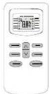
Remote controller supporter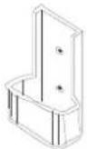
Batteries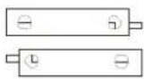
Vinyl tape
Drain hose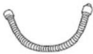
Hole cover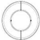
Screw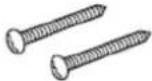
Insulation material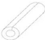
2.3 Tools
Tool name Picture Tool name Picture Tool name Picture Standard Wrench 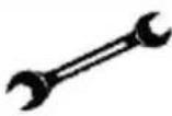
Pipe Cutter 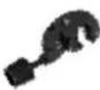
Vacuum Pump 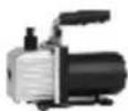
Adjustable/Crescent Wrench 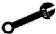
Screw drivers (Phillips & Flat blade) 
Safety Glasses 
Torque Wrench 
Manifold and Gauges 
Work Gloves 
Hex Keys or Allen Wrenches 
Level 
Refrigerant  S
SDrill & Drill Bits 
Flaring tool 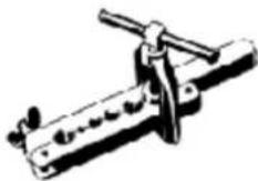
Micron Gauge 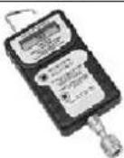
Hole Saw 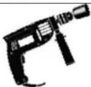
Clamp on Amp Meter 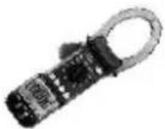
2.4 Position
Indoor unit
● Install the indoor unit level on a strong wall that is not subject to vibrations
- The inlet and outlet ports should not be obstructed: the air should be able to blow all over the room.
- Do not install the unit near a source of heat, steam or flammable gas.
- Do not install the unit in too windy or dusty places.
- Do not install the unit where people often pass. Select a place where the air discharge and operating sound level will not disturb the neighbors.
● Install the unit where connection between indoor and outdoor unit is as easy as possible.
● Install the unit where it is easy to drain the condensed water.
- Check the machine operation regularly and leave the necessary spaces as shown in the picture.
- Install the indoor unit where the filter can be easily accessible.
OUTDOOR UNIT
- Do not install the outdoor unit near sources of heat, steam or flammable gas.
- Do not install the unit in too windy or dusty places.
- Do not install the unit where people often pass. Select a place where the air discharge and operating sound level will not disturb the neighbors.
- Avoid installing the unit where it will be exposed to direct sunlight (other wise use a protection, if necessary, that should not interfere with the air flow).
- Leave the spaces as shown in the picture for
● The air to circulate freely.
● Install the outdoor unit in a safe and solid place.
- If the outdoor unit is subject to vibration, place rubber gaskets onto the feet of the unit.
- Install the indoor unit in the room to be air conditioning, avoiding to installation in corridors or communal areas.
- Install the indoor unit at a height of at least 2.5m from the ground.
Minimum space to be left (mm) showing in the picture.
2.5 Electricity and wiring
Safety precaution
1) Must follow the electric safety regulations when installing the unit.
2) According to the local safety regulations, use qualified power supply circuit and air switch.
3) Make sure the power supply matches with the requirement of air conditioner. Unstable power supply or incorrect wiring may result in electric shock, fire hazard or malfunction. Please install proper power supply cables before using the air conditioner.
The power cord should be selected according to the following specifications sheet.
Appliance Amps(A) Wire Size (mm2) 5 0 10 1.0 13 1.5 18 1.6 25 2.0 30 2.5
2.6 IDU Installation
To install, proceed as follows:
2.6.1 Installation of the mounting plate.
1) By using a level, put the mounting plate in a perfect square position vertically and horizontally.
2) Drill 32mm deep holes in the wall to fix the plate.
3) Insert the plastic anchors into the hole.
4) Fix the mounting plate by using the provided tapping screws.
5) Check that the mounting plate is correctly fixed.

9K(770X)

12K(770X)

18K(900X)

24K(1010X)

36K(1186A)

natural_image
Technical line drawing of a mechanical component with mounting holes and internal channels (no text or symbols)
Note: The shape of the mounting plate may be different from the one above, but installation method is similar.
2.6.2 Drilling a hole in the wall for the piping
1) Decide where to drill the hole in the wall for the piping (if necessary) according to the position of the mounting plate
2) Install a flexible flange through the hole in the wall to keep the latter intact and clean.
Indoors

Out doors
The hole must slope downwards towards the exterior. Note: Keep the drain pipe down towards the direction of the wall hole, otherwise leakage may occur.
1.6.3 Electrical connections---Indoor unit
1). Lift the front panel.
2). Take off the cover as indicated in the picture (by removing a screw or by breaking the hooks).
3). For the electrical connections, see the circuit diagram on the right part of the unit under the front panel.
4). Connect the cable wires to the screw terminals by following the numbering, Use wire size suitable to the electric power input (see name plate on the unit) and according to all current national safety code requirements.
5). The cable connecting the outdoor and indoor units must be suitable for outdoor use.
6). The plug must be accessible also after the appliance has been installed so that it can be pulled out if necessary.
7). An efficient earth connection must be ensured.
8). If the power cable is damaged, it must be replaced by an authorized Service Centre.

★ Refrigerant piping connection
The piping can be run in the 3 directions indicated by numbers in the picture. When the piping is run in direction 1 or 3, cut a notch along the groove on the side of the indoor unit with a cutter.
Run the piping in the direction of the wall hole and bind the copper pipes, the drain pipe and the power cables together with the tape with the drain pipe at the bottom, so that water can flow freely.

1.6.4 Connecting the pipes.
- Do not remove the cap from the pipe until connecting it, to avoid dampness or dirt from entering.
- If the pipe is bent or pulled too often, it will become stiff. Do not bend the pipe more than three times at one point.
- When extending the rolled pipe, straighten the pipe by unwinding it gently as shown in the picture.


natural_image
Pure diagram of a coiled tube with directional arrows, no text or symbols present
Extending the rolled pipe
2.6.5 Connections to the indoor unit
1). Remove the indoor unit pipe cap (check that there is no debris inside).
2). Insert the fare nut and create a flange at the extreme end of the connection pipe.

3). Tighten the connections by using two wrenches working in opposite directions.

Capacity(Btu/h) Pipe Size (Torque) Gas Liquid 7/9/12K 3/8" (4.2kg.m) 1/4" (1.8kg.m) 18K 1/2" (5.5kg.m) 1/4" (1.8kg.m) 24K 5/8" (6.6kg.m) 3/8" (4.2kg.m) 36K 5/8" (6.6kg.m) 1/4" (1.8kg.m)
Wrap the insulation material around the connecting portion.
\- Overlap the connection pipe insulation material and the indoor unit pipe insulation material. Bind them together with vinyl tape so that there is no gap.

Wrap the area which accommodates the rear piping housing section with vinyl tape.

\- Bundle the piping and drain hose together by wrapping them with vinyl tape over the range within which they fit into the rear piping housing section.

2.6.6 Indoor unit condensed water drainage
The indoor unit condensed water drainage is fundamental for the success of the installation.
1). Place the drain hose below the piping, taking care not to create siphons.
2). The drain hose must slant downwards to aid drainage.
3). Do not bend the drain hose or leave it protruding or twisted and do not put the end of it in water. If an extension is connected to the drain hose, ensure that it is lagged when it passes into the indoor unit.
4). If the piping is installed to the right, the pipes, power cable and drain hose must be lagged and secured onto the rear of the unit with a pipe connection.
When extending the drain hose at the indoor unit, install the drain pipe.

\- Insert the pipe connection into the relative slot.
\- Press to join the pipe connection to the base.

2.7 ODU Installation
● The outdoor unit should be installed on a solid wall and fastened securely.
● The following procedure must be observed before connecting the pipes and connecting cables : decide which is the best position on the wall and leave enough space to be able to carry out maintenance easily.
● Fasten the support to the wall using screw anchors which are particularly suited to the type of wall;
- Use a larger quantity of screw anchors than normally required for the weight they have to bear to avoid vibration during operation and remain fastened in the same position for years without the screws becoming loose.
● The unit must be installed following the national regulations.
Outdoor unit condensed water drainage
(only for heat pump models)
The condensed water and the ice formed in the outdoor unit during heating operation can be drained away through the drain pipe.
1) Fasten the drain port in the 25mm hole placed in the part of the unit as shown in the picture.
2) Connect the drain port and the drain pipe.
Pay attention that water is drained in a suitable place.

Electronic connections
1. Take the cover away.
2. Connect the cable wires to the terminal board using the same numbering as in the indoor unit.
3. For the electrical connections, see the wiring diagram on the back of the cover
4. Fasten the cables with a cable-clamp.
5. An efficient earth connection must be ensured.
6. Replace the covers.
Wiring diagram on the back of the cover

Connecting the pipe
Screw the flare nuts to the outdoor unit coupling with the same tightening procedures described for the indoor unit.
Note: If the tightening torque is not sufficient, there will probably be some leakage. With excessive tightening torque there will also be some leakage, as the flange could be damaged.

flowchart
graph TD
    A["connection pipes"] --> B["flare nuts"]
    B --> C["liquid tap"]
    C --> D["gas tap"]
    D --> E["indoor unit"]
    E --> F["gas valve"]
    F --> G["service port nut"]
    G --> H["protection caps"]
    I["Liquid valve tap"] --> F
    style A fill:#f9f,stroke:#333
    style B fill:#ccf,stroke:#333
    style C fill:#cfc,stroke:#333
    style D fill:#fcc,stroke:#333
    style E fill:#cff,stroke:#333
    style F fill:#ffc,stroke:#333
    style G fill:#cfc,stroke:#333
    style H fill:#fcc,stroke:#333
2.8 Vacuum and gas leakage test
1. Use vacuum Pump
1) Air and humidity left inside the refrigerant circuit can cause compressor malfunction. After having connected the indoor and outdoor units, bleed the air and humidity from the refrigerant circuit by using a vacuum pump.
2) Open the piezometer and operation for 10-15minutes to check if the pressure of piezometer remains in -0.1Mpa.
3) Close the vacuum pump and maintain this status for 1-2min to check if the pressure of piezometer remains in -0.1Mpa. If the pressure decrease, there may be leakage.
4) Remove the piezometer, open the valve core of liquid valve and gas valve completely.
5) Tighten the screw caps of valve and refrigerant charging vent.

2. Leakage Detection
1). With leakage detection.
Check if there is leakage with leakage detection.
2). With soap water. If leakage detection is not available, please use soap water for leakage detection. Apply soap water at the suspected position and keep the soap water for more than 3min. If there are air bubbles coming out of this position, there a leakage.
2.9 Final test
1 Preparation of test operation.
- The client approves the air conditioner installation.
- Specify the important notes for air conditioner to the client.
2 Method of test operation
- Put through the power, press ON/OFF button on the remote controller to start operation.
- Press MODE button the select AUTO, COOL, DRY, FAN and HEAT to check whether the operation is normal or not.
If ambient temperature is lower than 16^ , the air conditioner can't start cooling.
3. Maintenance
3.1 Failure code
Code Reason Remark E0 IDU & ODU Communication failure The IDU & ODU wiring connection correct? E1 IDU Room Temperature sensor failure. (IDU RT failure) IDU sensor and PCB. E2 IDU Coil temperature sensor failure. (IDU IPT failure) IDU sensor and PCB. E3 ODU Coil temperature sensor failure. (OPT) ODU coil sensor and ODU PCB E4 AC Cooling system abnormal Gas leakage? 2-way or 3-way valve blocked etc. E5 IDU/ODU mismatched failure (specially performance test on the production line) / E6 IDU PG Fan motor / DC fan motor works abnormal (IDU failure) Fan motor, fan blade and PCB. E7 ODU Ambient Temperature sensor failure ODU ambient sensor and ODU PCB. E8 ODU Discharge Temperature sensor failure. ODU discharge sensor and ODU PCB. E9 IPM / Compressor driving control abnormal. ODU PCB , compressor, etc. EA ODU Current Test circuit failure ODU PCB broken? Eb The Communication abnormal of Main PCB and Display board (IDU failure) Display board and main PCB. EE ODU EEPROM failure. 1. ODU PCB broken?2. Try to re-power on AC unit. EF ODU DC fan motor failure. Fan motor, ODU PCB. EU ODU Voltage test circuit abnormal. ODU PCB. P0 IPM module protection. ODU PCB P1 Over / under voltage protection. 1. ODU PCB broken?2. Power supply abnormal? P2 Over current protection. 1. ODU PCB broken?2. Power supply abnormal? P4 ODU Discharge pipe Over temperature protection. Please check the troubleshooting for detail. P5 Sub-cooling protection on Cooling mode. Please check the troubleshooting for detail. P6 Overheating protection on Cooling mode. Please check the troubleshooting for detail. P7 Overheating protection on Heating mode. Please check the troubleshooting for detail. P8 Outdoor Over temperature/Under temperature protection. Please check the troubleshooting for detail. P9 Compressor driving protection (Load abnormal). Please check the troubleshooting for detail. PA Communication failure for TOP flow unit/Preset mode conflict. (IDU failure) Please check the troubleshooting for detail. F0 Infrared Customer feeling test sensor failure. (IDU failure) Querying by press remote controller F1 Electric Power test module failure. (IDU failure) Querying by press remote controller F2 Discharge temperature sensor failure PROTECTION. Please check the troubleshooting for detail. F3 ODU coil temperature failure PROTECTION.. Please check the troubleshooting for detail. F4 Cooling system gas flow abnormal PROTECTION. Please check the troubleshooting for detail. F5 PFC PROTECTION Please check the troubleshooting for detail. F6 The Compressor lack of phase / Anti-phase PROTECTION. Please check the troubleshooting for detail. F7 IPM Module temperature PROTECTION Please check the troubleshooting for detail. F8 4-Way Value reversing abnormal.. Please check the troubleshooting for detail. F9 The module temperature test circuit failure. ODU PCB FA The compressor Phase-current test circuit failure. ODU PCB Fb Limiting/Reducing frequency for Over load protection on Cooling/Heating mode. Querying by press remote controller FC Limiting/Reducing frequency for High power consumption protection. Querying by press remote controller FE Limiting/Reducing frequency for Module current protection ( phase current of compressor). Querying by press remote controller FF Limiting/Reducing frequency for Module temperature protection. Querying by press remote controller FH Limiting/Reducing frequency for Compressor driving protection. Querying by press remote controller FP Limiting/Reducing frequency for anti-condensation protection. Querying by press remote controller FU Limiting/Reducing frequency for anti-frost protection. Querying by press remote controller Fj Limiting/Reducing frequency for Discharge over temperature protection. Querying by press remote controller Fn Limiting/Reducing frequency for ODU AC Current protection. Querying by press remote controller Fy Gas leakage protection Please check the troubleshooting for detail. bf TVOC sensor failure (IDU failure, optional) Querying by press remote controller bc PM2.5 sensor failure (IDU failure, optional) Querying by press remote controller bj Humidity sensor failure. (IDU failure) Querying by press remote controller
Note: Remote controller FAILURE CODE Querying function
As shown in the failure codes, some of the codes (Fb\~bj) need to press remote control for inspection.
While unit on operation, press the ECO button 8 times with 8 seconds, the buzzer BIBI 2 times, you can inspect the special failure code as Fb \~Fn, bj etc.
3.2 Trouble shooting
3.2.1 E0 ---IDU & ODU communication failure

flowchart
graph TD
    A["Start"] --> B["Display E0"]
    B --> C{IDU wiring connection correct?}
    C -->|No| D["Check and re-connect"]
    C -->|Yes| E{Check communication wiring and the connection, in good condition?}
    D -->|No| F["Replace/ re-connect"]
    D -->|Yes| G{E0 disappear?}
    F -->|No| H{E0 disappear?}
    F -->|Yes| I["End"]
    G -->|No| J{ODU wiring Connection correct?}
    J -->|No| K["Check and re-connect"]
    J -->|Yes| L{ODU main power supply from IDU?}
    K -->|No| M{Check voltage from IDU terminal btw L, N. is there 220V?}
    M -->|No| N["Replace IDU PCB"]
    M -->|Yes| O{Is the ODU PCB LED5 ON?}
    N -->|No| P["Replace ODU PCB"]
    N -->|Yes| Q["End"]
    O -->|Yes| R{E0 disappear?}
    R -->|No| S{E0 disappear?}
    R -->|Yes| T["Check the power supply connection"]
    T --> U["Replace or reconnect"]
    U --> V["Flash"]
    S --> V
    S --> W{Is the ODU PCB LED5 ON?}
    W -->|No| X["ON constantly"]
    W -->|Yes| Y["End"]
    X --> Z["Replace ODU PCB"]
    Y --> AA["End"]
Remark: 1. if the communication wiring 1(S) is not well connected, the ODU LED5 will light ON always.
2. When unit works normal, there is a variable DC voltage (0\~24V) btw 1(S) & N. and LED5 flashes.
3.2.2 E1, E2 ---IDU Room temperature sensor and/or coil temperature sensor failure.

flowchart
graph TD
    A["Start"] --> B["Display E1 or E2"]
    B --> C{Is the sensor well connected to PCB}
    C -->|No| D["Re-connect"]
    D --> E{E1/E2 disappear?}
    E -->|Yes| F{Multi-meter check the sensor, is it open or short circuit?}
    E -->|No| G["Replace the sensor"]
    G --> H{The malfunction eliminated?}
    H -->|Yes| I["End"]
    H -->|No| F
    F -->|Yes| G
    F -->|No| J["Replace IDU PCB"]
    J --> K["End"]
3.2.3 E4 --- AC Cooling system abnormal (Gas not enough)

flowchart
graph TD
    A["Start"] --> B["Display E4"]
    B --> C["Check the pressure"]
    C --> D{AC pressure correct? (cooling:0.8-1.3Mpa,/ heating 2.0-3.6Mpa)}
    D -->|Yes| E{Check the sensor short or open?}
    D -->|No| F{Check the valves open or not}
    F -->|Yes| G["Lower than 0.8 Mpa in cooling, 2.0 Mpa in heating, is not enough"]
    F -->|No| H["Open the valves"]
    E -->|Yes| I["Add gas"]
    E -->|No| J["Replace the main PCB"]
    I --> K["E4 display?"]
    K -->|Yes| L["System block"]
    K -->|No| M["End"]
    L --> N["Maintain the system"]
3.2.4 E6----IDU ventilation failure (PG and DC fan motor only)

flowchart
graph TD
    A["Start"] --> B["Display E6"]
    B --> C["Turn the fan blades by hand while power-off"]
    C --> D{Can the fan blades run smoothly?}
    D -->|No| E["Adjust the motor and blade assembly so that rotor can run smoothly."]
    D -->|Yes| F{Fan motor well connected to PCB}
    E --> G{E6 disappear?}
    G -->|No| H["End"]
    G -->|Yes| I["Check and reconnect"]
    I --> J{E6 disappear?}
    J -->|No| K["End"]
    J -->|Yes| L{Multi-meter check resistance of fan motor, is there open or short circuit of winding?}
    L -->|Yes| M["Replace fan motor"]
    M --> N{E6 disappear?}
    N -->|No| K
    N -->|Yes| O["End"]
    O --> P["Replace IDU PCB"]
    P --> Q["End"]
3.2.5 E3, E7 or E8----ODU Coil temperature sensor, Ambient temperature sensor or Discharge temperature sensor failure.
When any of the sensor resistance open or short circuit, unit will display failure code as E3/E7 or E8, IDU and ODU turns off. When the sensor resistance recovery, unit revert to be standby, customer can switch on the unit directly.

flowchart
graph TD
    A["Start"] --> B["Display E3, E7 or E8"]
    B --> C{Is the sensor well connected to ODU PCB?}
    C -->|No| D["Re connect"]
    D --> E{Problem solved?}
    E -->|Yes| F["Replace sensor"]
    E -->|No| G{Multi-meter check the sensor resistance. Open or short circuit?}
    G -->|Yes| H["Replace sensor"]
    G -->|No| I["End"]
    H --> J{Problem solved?}
    J -->|Yes| K["Replace ODU PCB"]
    J -->|No| L["End"]
    I --> M["End"]
3.2.6 E9---ODU IPM / Compressor drive fault
If unit have 6 times stopping works for IPM protection (P0) continuously, it will display E9 error, and unit can't be recovered to operation, except press ON/OFF button.

flowchart
graph TD
    A["Display E9"] --> B{Re-power on unit running for 30 min, and check the failure code display}
    B -->|No| C["Normal protection"]
    B -->|Yes| D["Display F9 or FA first then E9"]
    D --> E["Replace ODU PCB"]
    B --> F["Display F5,F6,or F7 first then E9"]
    F --> G["Solution as F5,F6,or F7"]
    B --> H["Display P0 or P2 first then E9"]
    H --> I["Solution as P0 or P2"]
    B --> J{Failure disappear?}
    J -->|No| K["Replace compressor"]
    J -->|Yes| L["End"]
    K --> M["End"]
Remark:
1. F9 code
Reason: The IPM module temperature test circuit failure.
Solution: Replace the ODU PCB.
2. FA code
Reason: The compressor phase-current test circuit failure.
Solution: Replace the ODU PCB.
3.2.7 EF---ODU DC fan motor failure

flowchart
graph TD
    A["Shut off"] --> B{Check the fan blade by hand, can it rotate freely}
    B -->|No| C["Re install the DC motor"]
    C --> D{Works normal?}
    D -->|Yes| E["End"]
    D -->|No| F{Fan motor well connect to PCB}
    F -->|Yes| G["Re-connect"]
    F -->|No| H{Works normal?}
    H -->|Yes| I["End"]
    H -->|No| J{Works normal?}
    J -->|Yes| K["Check the fan motor, can it operate or not."]
    K --> L{Works normal?}
    L -->|Yes| M["End"]
    L -->|No| N["Replace fan motor"]
    N --> O{Works normal?}
    O -->|No| P["Replace ODU PCB"]
    O -->|Yes| Q["End"]
    Q --> R["End"]
3.2.8 EU---ODU voltage test sensor failure
After power relay works, when tested voltage effective value less than 50V for 3s continuously, unit will display EU.

flowchart
graph TD
    A["Start"] --> B["Display EU"]
    B --> C{Test voltage btw ODU terminal L/N, more than 50V~?}
    C -->|No| D["Check while voltage become normal"]
    D --> E{Unit works?}
    E -->|Yes| F["Replace ODU PCB"]
    E -->|No| G["End"]
    F --> H["End"]
    G --> C
3.2.9 P0---IPM protection
When overheat or overcurrent for IPM, AC unit will display P0protection.

flowchart
graph TD
    A["Display P0"] --> B{Restart unit. It works normal?}
    B -->|No| C{Wiring connection U/V/W correct?}
    C -->|Yes| D["Re-connect"]
    C -->|No| E["P0 disappear?"]
    E --> F{Can compressor start up?}
    F -->|No| G{test voltage btw U/V/W, (normally from DC 20~200V.)}
    F -->|Yes| H{ODU fan motor no works or too slowly?}
    H -->|No| I{AC pressure correct? (cooling:0.8-1.3Mpa,/ heating 2.0-3.6Mpa)}
    H -->|Yes| J["Replace ODU fan motor"]
    I -->|No| K{Is the condenser and/or evaporator too dirty?}
    I -->|Yes| L["Clean it"]
    K -->|Yes| M{Capillary blocked?}
    K -->|No| N["Replace capillary"]
    L -->|Yes| O["End"]
    M -->|No| P["Replace compressor"]
    M -->|Yes| Q["End"]
    N --> R["End"]
3.2.10 P1--- Over / under voltage protection
1. Test voltage between L &N, When the power supply V>AC260V or VAC155V.
2. Test voltage on the big size electrolytic capacitor of ODU PCB, When DC busbar voltage V>DC420V or V
flowchart
graph TD
    A["Display P1"] --> B{Is the power supply voltage btw145-260V?}
    B -->|No| C["Wait until the AC voltage recovery"]
    B -->|Yes| D{Is the power supply voltage btw145-260V?}
    C --> D
    D -->|No| E{Is the busbar voltage btw150-420V?}
    D -->|Yes| F["Replace ODU PCB"]
    E -->|No| G["Wait until the busbar voltage recovery"]
    E -->|Yes| H{Unit works normal?}
    G --> H
    H -->|No| E
    H -->|Yes| I["End"]
3.2.11 P2---Over Current protection
When the AC unit running current more than I_max , it will stop and display P2 protection.
Note: for different AC model, I_max has difference valve.

flowchart
graph TD
    A["Display P2"] --> B{ODU fan motor works?}
    B -->|No| C["Replace fan motor"]
    B -->|Yes| D{IDU filter or ODU condenser too dirty?}
    C --> D
    D -->|Yes| E["Clean IDU filter or condenser"]
    D -->|No| F["Re-start the unit, P2 disappear?"]
    E --> F
    F --> G["Replace ODU PCB"]
    G --> H["End"]
3.2.12 P4 ---ODU Discharge temperature overheating protection

flowchart
graph TD
    A["Display P4"] --> B{ODU temperature higher than 60°C?}
    B -->|Yes| C["Normal protection"]
    B -->|No| D{Unit operate?}
    D -->|No| E{ODU location acceptable?}
    E -->|No| F{Enough space for ventilation?}
    F -->|Yes| G["Adjust ODU installation"]
    F -->|No| H{Condenser too dirty? or filter blocked?}
    H -->|Yes| I["Clean IDU filter or ODU condenser."]
    H -->|No| J{IDU/ODU fan motor running slowly or stopped?}
    J -->|No| K{Fan blade blocked?}
    K -->|Yes| L["Adjust"]
    K -->|No| M["Replace fan motor or PCB"]
    L --> N{Problem solved?}
    N -->|Yes| O{Capillary blocked?}
    N -->|No| P{Is the unit gas pressure normal? (cooling0.8-1.3Mpa, heating2.0-3.6Mpa)}
    O -->|Yes| Q["Change gas"]
    O -->|No| R["Replace ODU"]
    Q --> S{Problem solved?}
    S -->|Yes| T["End"]
    S -->|No| R
    S -->|No| U["Replace ODU"]
3.2.13 P5---Sub-cooling protection on Cooling/Dry mode
On Cooling or Dry mode, when IDU evaporator coil temperature IPT<1°C continuously for 3 min after compressor start up for 6 min, CPU will switch off outdoor unit and show P5 failure code.

flowchart
graph TD
    A["Display P5"] --> B["Switch on unit after minutes"]
    B --> C{Display P5}
    C -->|Yes| D{IDU filter dirty?}
    C -->|No| E["Normal"]
    D -->|Yes| F["Clean filter"]
    D -->|No| G{P5 disappear?}
    G -->|Yes| H{IDU air inlet blocked?}
    G -->|No| I{Can fan blade rotate freely?}
    H -->|Yes| J["Clean"]
    H -->|No| I
    I -->|Yes| K{P5 disappear?}
    I -->|No| L{Fan motor works too slow or stopped}
    J -->|Yes| M["Check and repair fan blade"]
    J -->|No| N{P5 disappear?}
    K -->|Yes| O["Replace motor"]
    K -->|No| P{Fan motor defect?}
    L -->|Yes| Q["Replace motor"]
    L -->|No| P
    M --> R{Sensor IPT abnormal?}
    N --> R
    O --> R
    P --> R
    Q --> S["Replace sensor"]
    R --> T["End"]
    S --> U["Replace IDU PCB"]
    T --> U
    U --> V["End"]
    style A fill:#f9f,stroke:#333
    style V fill:#ccf,stroke:#333
3.2.14 P6---Overheating protection on Cooling mode
On Cooling or Dry mode, when ODU condenser coil temperature OPT ≥ 62^ C , MCU will switch off outdoor unit and show P6 failure code.

flowchart
graph TD
    A["Display P6"] --> B{ODU fan motor works normal?}
    B -->|No| C{Fan motor broken?}
    B -->|Yes| D{Sensor loosing from connector?}
    C -->|Yes| D
    C -->|No| E["Replace fan motor"]
    E --> F{P6 disappear?}
    F -->|Yes| D
    F -->|No| G{P6 disappear?}
    G -->|Yes| H["Re-connect sensor"]
    G -->|No| I{The sensor open or short circuit?}
    H --> I
    I -->|Yes| J["Replace OPT sensor"]
    I -->|No| K{P6 disappear?}
    J --> L["Replace ODU PCB"]
    K --> M["End"]
    L --> N["End"]
3.2.15 P7---Overheating protection on Cooling mode
On heating mode, when IDU evaporator coil temperature IPT≥62°C, ODU PCB will switch off outdoor unit and show
P7 failure code.

flowchart
graph TD
    A["Display P7"] --> B{ODU fan motor works normal?}
    B -->|No| C{Fan motor broken?}
    B -->|Yes| D["Replace fan motor"]
    C -->|No| E{P7 disappear?}
    C -->|Yes| F{Sensor loosing from connector?}
    D --> F
    E -->|No| F
    F -->|Yes| G["Re-connect sensor"]
    F -->|No| H{P7 disappear?}
    G --> H
    H -->|Yes| I{The sensor open or short circuit?}
    H -->|No| J["Replace IPT sensor"]
    I -->|Yes| K["Replace IDU PCB"]
    I -->|No| L["End"]
    J --> M["P7 disappear?"]
    K --> M
    L --> M
3.2.16 P8---Outdoor Overtemperature/Under-temperature protection
When environment temperature as below condition, the compressor will stop working, after 200s delay, the IDU will show P8 failure code.
(1). On Cooling or Dry mode: ODU ambient temperature: OAT<-20°C or OAT>63°C;
(2). On Heating mode:
a. OAT≥40°C
b. 30^ C < OAT ≤ 40^ C and RT > 35^ C

flowchart
graph TD
    A["Display P8"] --> B{Ambient temperature under spec. range?}
    B -->|No| C{No enough space for ODU ventilation?}
    B -->|Yes| D{P8 disappear?}
    C -->|Yes| D
    C -->|No| E["Change ODU location"]
    E --> F{P8 disappear?}
    F -->|No| D
    F -->|Yes| G{The sensor open or short circuit?}
    G -->|No| H["Replace OAT sensor"]
    H --> I{P8 disappear?}
    I -->|No| G
    I -->|Yes| J["Replace ODU PCB"]
    J --> K["End"]
    G -->|Yes| L["Replace OAT sensor"]
3.2.17 P9---The compressor driving protection (the compressor load abnormal)
When compressor start up or in the process of operation, if:
(1). MCU can't test the feedback signal from compressor, or
(2). Tested a abnormal signal from compressor, or
(3). The compressor startup abnormal.
The outdoor unit will shut off, and show P9 protection.
(The unit will re-startup 6 times continuously, if it still can't work normal, then show P9 code)

flowchart
graph TD
    A["Display P9"] --> B{Check the compressor wires U/V/W sequence & connection, CORRECT?}
    B -->|No| C["Re-correct wires"]
    C --> D{Still P9?}
    D -->|Yes| E{Starts up the unit less than 3 minutes while it stopped?}
    D -->|No| F["End"]
    E -->|Yes| G["Normal protection as the High pressure and Low pressure not balance."]
    G --> H["Re-start after 3minutes"]
    H --> I{Still P9?}
    I -->|Yes| J["Replace ODU PCB"]
    I -->|No| K["End"]
    J --> L["End"]
3.2.18 F4---Cooling system Gas flow abnormal protection
When compressor startup, unit will check the variation of IDU coil temperature. If there is mistake installer forgetting to open the 2-way or 3-way valve on ODU, the gas can't flow in the cooling system, it will show F4 protection.

flowchart
graph TD
    A["Start"] --> B["Display F4"]
    B --> C{Check the 2-way valve and 3-way valve opened?}
    C -->|Yes| D["Open the valve"]
    D --> E{F4 disappear?}
    E -->|No| F{The IPT sensor open or short?}
    E -->|Yes| G["Replace the sensor"]
    G --> H["End"]
    C -->|No| F
    F -->|Yes| G
3.2.19 F5---PFC Protection
PFC Overcurrent protection

flowchart
graph TD
    A["F5 Code"] --> B{Display F5 by random?}
    B -->|Yes| C["Check the power supply, is it abnormal? (this is normal protection)"]
    B -->|No| D["Display F5 frequently"]
    D --> E["Switch off the unit for 3 minutes and re-switch on"]
    E --> F{Still F5?}
    F -->|Yes| G["Replace ODU PCB"]
    F -->|No| H["End"]
    G --> H
3.2.20 F6 The Compressor Lack of phase / Anti-phase protection.
If ODU PCB can't test one, or even three phase of compressor current, it will show F6 protection.

flowchart
graph TD
    A["Display F6"] --> B{Check compressor wiring connector, is it well connected?}
    B -->|No| C["Re-connect"]
    B -->|Yes| D{The Compressor wiring in good quality?}
    C --> D
    D -->|No| E["Replace the wires"]
    D -->|Yes| F["Compressor phase-current test circuit failure"]
    E --> G{Problem solved?}
    F --> G
    G -->|No| H["Replace compressor"]
    G -->|Yes| I["End"]
    H --> J{Problem solved?}
    J -->|No| D
    J -->|Yes| K["End"]
3.2.21 F7---Module temperature protection.
IPM overtemperature protection, when IPM temperature more than 95°C, it will show F7.

flowchart
graph TD
    A["Display F7"] --> B{IPM well contact to heat sink?}
    B -->|No| C{Any dust or gap btw IPM & heat sink?}
    C -->|Yes| D["Clean or adjust the gap btw IPM and heat sink"]
    C -->|No| E{Check the screw fully fasten?}
    E -->|Yes| F["F7 disappear?"]
    E -->|No| G["Fix the screw"]
    D --> F
    F --> H{ODU cooling system abnormal? Compressor with big running current? (9,12K:6-7A, 18,24K:7-9A)}
    H -->|Yes| I{Low pressure normal? (0.8-1.2Mpa)}
    I -->|No| J{Is the 2/3way valve fully opened?}
    J -->|Yes| K["Open the valve"]
    J -->|No| L{Capillary blocked?}
    L -->|Yes| M["Replace capillary"]
    L -->|No| N{Condenser / evaporator dirty?}
    N -->|Yes| O["Clean condenser / evaporator"]
    N -->|No| P["End"]
    K --> Q["F7 disappear?"]
    M --> Q
    O --> Q
    Q --> R["IPM temperature circuit abnormal?"]
    R --> S["Replace ODU PCB"]
    S --> T["End"]
3.2.22 F8---4-Way Value Reversing abnormal
On heating mode, if IDU Coil temperature tested lower than Room temperature 5^ C or even more after compressor works for 8min, unit will show F8 code.

flowchart
graph TD
    A["Display F8"] --> B{the 4-way valve wiring connection correct?}
    B -->|No| C["Re-connect"]
    C --> D{F8 disappear?}
    D -->|Yes| E{Is there 220V voltage on the 4-way valve?}
    D -->|No| F{Multimeter test the valve coil resistance, does it open or short circuit?}
    F -->|Yes| G["Replace 4-way valve coil"]
    F -->|No| H["End"]
    G --> I{F8 disappear?}
    I -->|Yes| E
    I -->|No| J["Replace ODU PCB"]
    J --> K["End"]
    E -->|Yes| L["End"]
    E -->|No| M["End"]
9.2.23 Fy--- Gas leakage protection
After compressor works in high frequency for 9 min, if the temperature on IDU evaporator & ODU condenser has only a little variation comparing previous, but, the compressor discharge temperature on high level, then the unit will show Fy failure code.

flowchart
graph TD
    A["Display Fy"] --> B{Check the pipe connection, any gas leakage?}
    B -->|No| C["Check the room & evaporator coil temperature."]
    B -->|Yes| D["Repair and charge new gas as SPEC."]
    D --> E{Is the temperature difference more than 2°C btw RT & IPT after unit start 10min?}
    E -->|No| F{Any of the evaporator pipe blocked}
    E -->|Yes| G{Problem solved?}
    G -->|Yes| H["Replace the indoor PCB"]
    G -->|No| I{The sensor well connect to PCB?}
    I -->|No| J["Replace the evaporator"]
    I -->|Yes| K{Is malfunction eliminated?}
    K -->|Yes| L["End"]
    K -->|No| M["Replace the sensor"]
    I -->|Yes| N["Re-connect"]
    N --> K
    K -->|No| O["Replace the sensor open or short circuit?"]
    O --> P["End"]
4. Disassembly IDU & ODU
4.1. IDU Disassembly
Steps Reference photo 1. Before disassembly The orginal status. 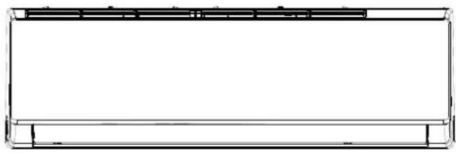
2. Disassembly front panel, display board and WIFI module. A. Open front panel.B. Remove one screw and take the displa box out from the panel.C. Release panel axis which shown in re arrows out from middle frame and take th panel out.D. Unscrew and take the WIFI module ou from middle frame. 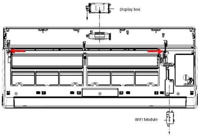
3. Remove the louver. Unlock the louver lockers (clip), bend the louver slightly by hands and remove it out from middle frame and stepping motor. 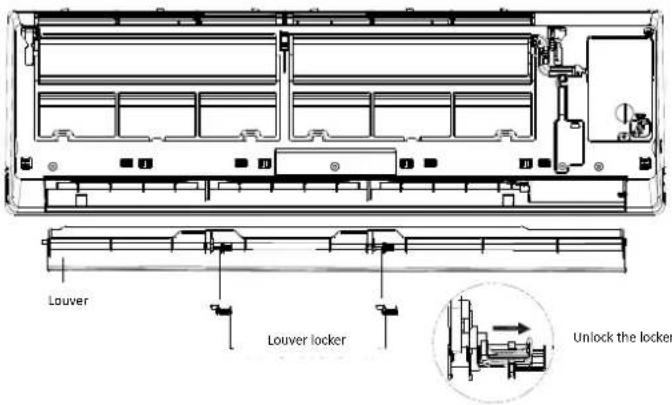
4. Remove the electric control box cover Unfix one screw on the cover of electric box, and remove the cover. 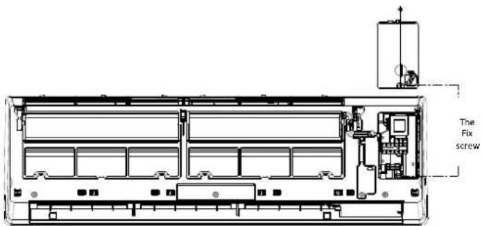
5. Remove the filter Push the filter upwards a little, you can take it out from unit. 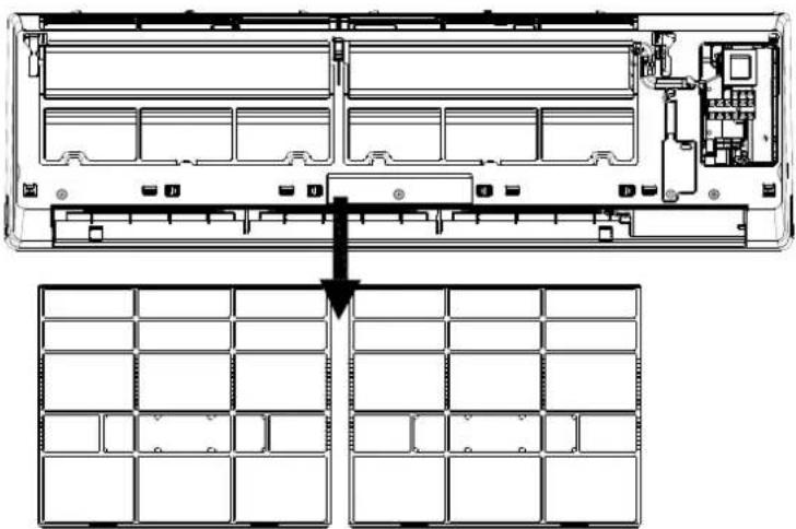
6. Disassembly the middle frame. A. Open the screw cover, and infix screw with cross screwdriver.B. Remove the middle frame by loosing the clasps with the unit base as shown in the picture and take the frame out. 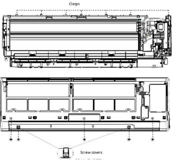
7. Disassembly the electric control box.
A. Remove the RT & IPT out from evaporator;
B. Unscrew all the earth ground wirings on the evaporator.
C. Take all the connectors out from PCB.
D. Unfix one screw of the control box with unit BASE FRAME, and take the control box out from unit.
Note: The right picture for your reference only, for the exact model the wiring connection may have a little difference.


8. Remove the PIPE COVER
Loosing the lower edge of the PIPE COVER from BASE FRAME, and take the COVER out from unit.

9. Disassembly the evaporator A. Unfix 2 screws of left side shown as picture.B. Unfix 2 screws of right side on motor cover/right support plate.C. Take the evaporator out from unit by uplifting the IUPUT/OUTPUT pipes slightly. 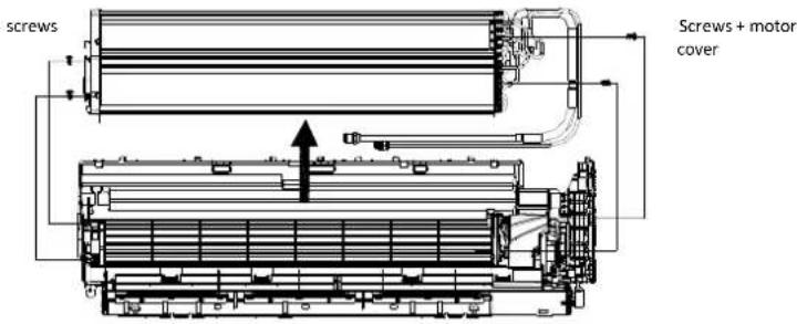
10. Remove the MOTOR COVER Unfix 4 screws on the motor cover with base frame. 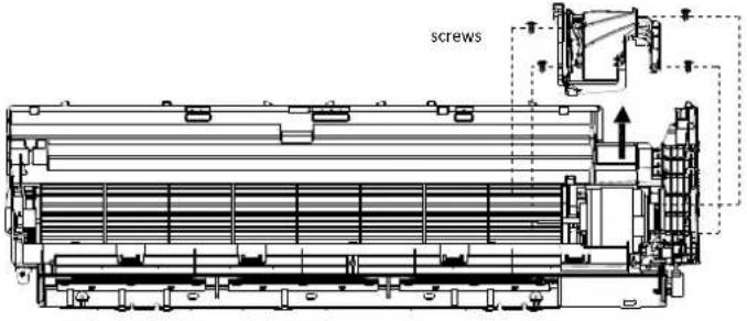
11. Disassembly fan motor and fan blade. A. Uplift the fan blade and fan motor, take the base frame out.B. Unfix one screw on the axis of fan motor, and you can get fan blade and fan motor separately. 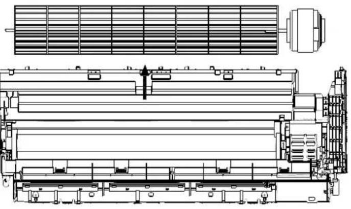

4.2 ODU Assembly
Step Reference step1: Remove the PCB Cover, valve Cover and top cover A 1). Unfix one screw on the PCB cover, you can take the cover out from unit.2). Unfix one screw on the valve cover, you can take it out easily. 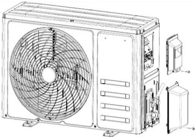
B Unfix screws btw the top cover with front panel, left and right plate, then you can take the top cover out. 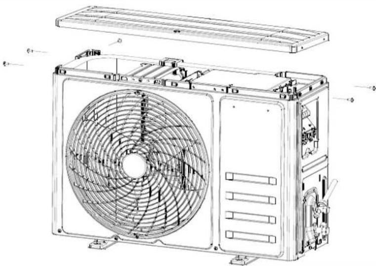
step2: Disassemble the Fan Guard and Front Panel A Unfix screws on front panel with fan guard. 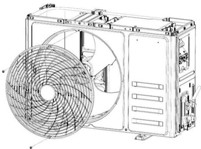
B ODU middle separate plate and base plate, uplift front panel you can take it out from unit. 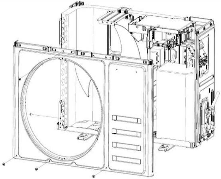
step3: Disassemble the Left and Right plate. A Unfix screws btwRight Plateand theElectric Boxassembly,ValvePlate,Base Plate,then you can takethe Right plate out. 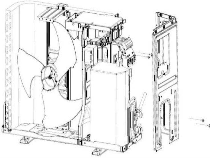
B Unfix screws btwLeft Plate, Baseplate andCondenser plate,you can take the leftplate out. 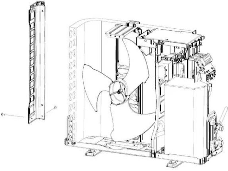
step4: Disassemble the Axis Fan Blade A Unscrew the fan blade nut, and take the blade out. 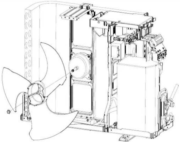
step5: Disassemble the electric box Unfix screw btw Electric Box and motor supporter etc. loosen the wiring clamp, then you can take the control box out. 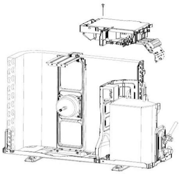
step6: take out the noise cotton
A Shown as picture to take the cotton out 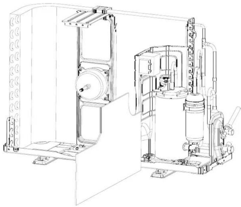
step7: Disassemble the separate plate Unfix the screw btw separate plate and unit, and take it out 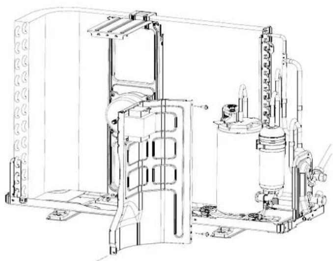
step8: Disassemble the 2 and 3-way valve Unfix screw btw Valve plate and base, you can take the 2-way and 3-way valve out by welding.Note:1). The welding can only place while no gas in the unit.2). Pay attention to the fire to prevent any injury. 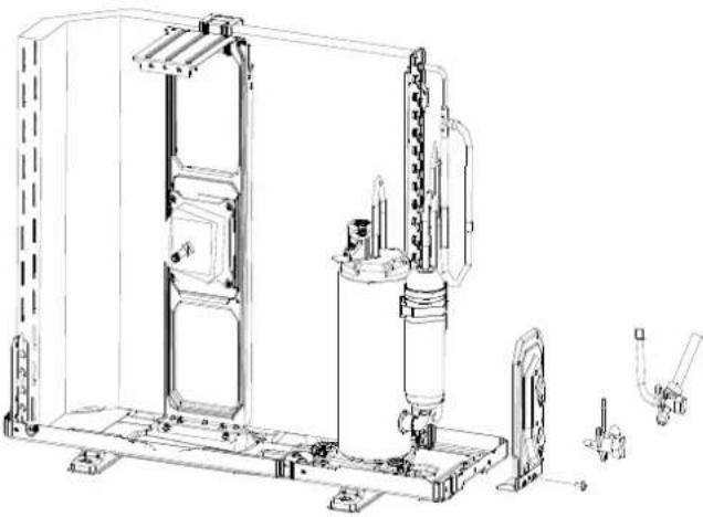
step9: Disassemble exhaust pipe and air return pipe assembly Take exhaust pipe and air return pipe assembly out from system by welding.Make sure no hurt to the compressor and nameplate, etc. 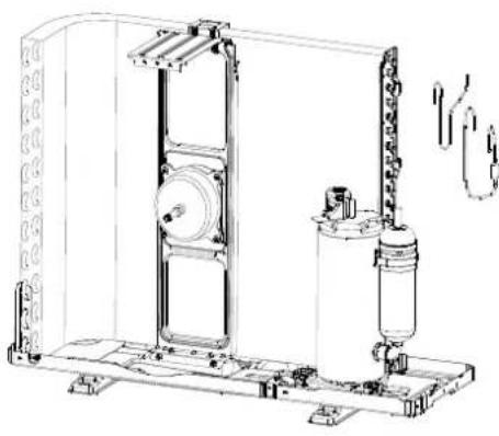
step10: Disassemble the compressor. Unscrew the nuts and take the compressor out. 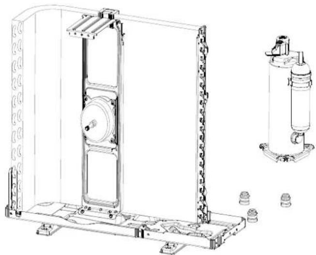
step11: Remove the fan motor and fan supporter.
Unfix screws btw fan motor with supporter, and supporter with base plate.
Note:
Pay attention to the motor wiring, it can't be taken out by force.

natural_image
Technical line drawing of a mechanical assembly with no visible text or symbols
APPENDIX
Appendix 1 The comparison table of Celsius-Fahrenheit temperature
Fahrenheit diplay temperature (°F) Fahrenheit (°F) Celsius (°C) Fahrenheit diplay temperature (°F) Fahrenheit (°F) Celsius (°C) Fahrenheit diplay temperature (°F) Fahrenheit (°F) Celsius (°C) 61 60.8 16 69/70 69.8 21 78/79 78.8 62/63 62.6 17 71/72 71.6 22 80/81 80.6 64/65 64.4 18 73/74 73.4 23 82/83 82.4 66/67 66.2 19 75/76 75.2 24 84/85 84.2 68 68 20 77 77 25 86 86
Appendix 2 The Pipe length and Gas charging

Mode Standard length (m) Refrigerant piping Max. length (m) A Additional refrigerant charging: Xg= B * (A-5m) B 9K 5.0 25 20 g/m 12K 5.0 25 20 g/m 18K 5.0 25 30 g/m 24K 5.0 25 30 g/m 30K 5.0 25 30 g/m 36K 5.0 25 30 g/m
Appendix 3 Pipes Flaring
Main cause for gas leakage is due to defect in flaring work. Carry out correct flaring work in the following procedure.
A. Cut the pipes and the cable.
1) Use the piping kit accessory or the pipes purchased locally.
2) Measure the distance between the indoor and the outdoor unit.
3) Cut the pipes a little longer than measured distance.
4) Cut the cable 1.5m longer than the pipe length.

B. Burrs removal
1) Completely remove all burrs from the cut cross section of pipe/tube.
2) Put the end of the copper tube/pipe in a down ward direction as you remove burrs in order to avoid dropping burrs into the tubing.

C. Flaring work
\- Carry out flaring work using flaring tool as shown below.
Outside diameter A mm inch mm ø6.35 1/4 1.0~1.3 ø9.52 3/8 0.8~1.0 ø12.7 1/2 0.5~0.8 ø15.88 5/8 0.5~0.8
Firmly hold copper pipe in a die in the dimension shown in the table above.

D. Check
1) Compare the flared work with figure below.
2) If flare is noted to be defective, cut off the flared section and do flaring work again.

Appendix 4 THERMISTOR TEMPERATURE CHARACTERISTICS
1). Indoor unit and outdoor exchange temperature and outside air temperature sensor temperature characteristics
TEMP. (°C) Resistance (k Ohm) Voltage of resistance TEMP. (°C) Resistance (k Ohm) Voltage of resistance TEMP. (°C) Resistance (k Ohm) Voltage of resistance -30 63.513 4.628 15 7.447 2.968 60 1.464 1.115 -29 60.135 4.609 16 7.148 2.918 61 1.418 1.088 -28 56.956 4.589 17 6.863 2.868 62 1.374 1.061 -27 53.963 4.568 18 6.591 2.819 63 1.331 1.035 -26 51.144 4.547 19 6.332 2.769 64 1.290 1.009 -25 48.488 4.524 20 6.084 2.720 65 1.250 0.984 -24 45.985 4.501 21 5.847 2.671 66 1.212 0.960 -23 43.627 4.477 22 5.621 2.621 67 1.175 0.936 -22 41.403 4.452 23 5.404 2.572 68 1.139 0.913 -21 39.305 4.426 24 5.198 2.524 69 1.105 0.890 -20 37.326 4.399 25 5.000 2.475 70 1.072 0.868 -19 35.458 4.371 26 4.811 2.427 71 1.040 0.847 -18 33.695 4.343 27 4.630 2.379 72 1.009 0.825 -17 32.030 4.313 28 4.457 2.332 73 0.979 0.805 -16 30.458 4.283 29 4.292 2.285 74 0.950 0.785 -15 28.972 4.252 30 4.133 2.238 75 0.922 0.765 -14 27.567 4.219 31 3.981 2.192 76 0.895 0.746 -13 26.239 4.186 32 3.836 2.146 77 0.869 0.728 -12 24.984 4.152 33 3.697 2.101 78 0.843 0.710 -11 23.795 4.117 34 3.563 2.057 79 0.819 0.692 -10 22.671 4.082 35 3.435 2.012 80 0.795 0.675 -9 21.606 4.045 36 3.313 1.969 81 0.773 0.658 -8 20.598 4.008 37 3.195 1.926 82 0.751 0.641 -7 19.644 3.969 38 3.082 1.883 83 0.729 0.625 -6 18.732 3.930 39 2.974 1.842 84 0.709 0.610 -5 17.881 3.890 40 2.870 1.800 85 0.689 0.595 -4 17.068 3.850 41 2.770 1.760 86 0.669 0.580 -3 16.297 3.808 42 2.674 1.720 87 0.651 0.566 -2 15.565 3.766 43 2.583 1.681 88 0.633 0.552 -1 14.871 3.723 44 2.494 1.642 89 0.615 0.538 0 14.212 3.680 45 2.410 1.604 90 0.598 0.525 1 13.586 3.635 46 2.328 1.567 91 0.582 0.512 2 12.991 3.590 47 2.250 1.530 92 0.566 0.499 3 12.426 3.545 48 2.174 1.495 93 0.550 0.487 4 11.889 3.499 49 2.102 1.459 94 0.535 0.475 5 11.378 3.452 50 2.032 1.425 95 0.521 0.463 6 10.893 3.406 51 1.965 1.391 96 0.507 0.452 7 10.431 3.358 52 1.901 1.357 97 0.493 0.441 8 9.991 3.310 53 1.839 1.325 98 0.480 0.430 9 9.573 3.262 54 1.779 1.293 99 0.467 0.419 10 9.174 3.214 55 1.721 1.262 100 0.455 0.409 11 8.795 3.165 56 1.666 1.231 12 8.433 3.116 57 1.613 1.201 13 8.089 3.067 58 1.561 1.172 14 7.760 3.017 59 1.512 1.143
Resistance at 25°C:5 kΩ.

TH1: indoor room temperature sensor and outside air temperature sensor
TH2: indoor exchange temperature sensor and outside exchange temperature sensor
Before measuring resistance, disconnect connectors as shown above.
1) Outdoor unit sensor temperature characteristics
TEMP. (°C) R min (k Ohm) R(t) (k Ohm) R max (k Ohm) TEMP. (°C) R min (k Ohm) R(t) (k Ohm) R max (k Ohm) TEMP. (°C) R min (k Ohm) R(t) (k Ohm) R max (k Ohm) -30 283.3 322.9 367.7 24 19.36 20.89 22.52 78 2.563 2.654 -29 267.4 304.4 346.3 25 18.55 20 21.54 79 2.481 2.567 -28 252.5 287.1 307.4 26 17.77 19.14 20.6 80 2.402 2.484 2.567 -27 238.5 270.9 307.4 27 17.03 18.32 19.7 81 2.327 2.404 2.483 -26 225.4 255.7 289.8 28 16.32 17.55 18.85 82 2.254 2.327 2.401 -25 213.1 241.4 273.3 29 15.65 16.81 18.04 83 2.183 2.253 2.323 -24 201.5 228 257.9 30 15 16.1 17.27 84 2.115 2.182 2.248 -23 190.6 215.5 243.4 31 14.39 15.43 16.54 85 2.05 2.113 -22 180.3 203.6 229.8 32 13.81 14.79 15.34 86 1.985 2.047 2.109 -21 170.7 192.5 217 33 13.25 14.18 15.17 87 1.922 1.983 -20 161.6 182.1 205 34 12.72 13.6 14.54 88 1.861 1.922 1.983 -19 153.1 172.3 193.7 35 12.21 13.05 13.93 89 1.802 1.862 1.923 -18 145 163.1 183.2 36 11.72 12.52 13.36 90 1.746 1.805 1.865 -17 137.5 154.4 173.2 37 11.26 12.01 12.81 91 1.692 1.75 -16 130.3 146.2 163.9 38 10.82 11.53 12.29 92 1.639 1.697 1.755 -15 123.6 138.5 155.1 39 10.29 11.07 11.78 93 1.589 1.646 1.703 -14 117.3 131.3 146.8 40 9.986 10.63 11.31 94 1.54 1.596 1.653 -13 111.3 124.4 139 41 9.6 10.21 10.85 95 1.493 1.549 1.604 -12 105.6 118 131.7 42 9.231 9.813 10.42 96 1.448 1.502 1.558 -11 100.3 111.9 124.7 43 8.878 9.43 10 97 1.404 1.458 1.512 -10 95.24 106.2 118.2 44 8.54 9.064 9.612 98 1.362 1.415 1.469 -9 90.49 100.8 112.1 45 8.217 8.714 9.233 99 1.321 1.373 1.426 -8 85.99 95.68 106.3 46 7.908 8.38 8.872 100 1.284 1.335 1.387 -7 81.75 90.86 100.8 47 7.612 8.06 8.526 101 1.245 1.296 1.348 -6 77.74 86.31 95.74 48 7.328 7.754 8.196 102 1.209 1.258 1.309 -5 73.94 82.01 90.88 49 7.057 7.461 7.88 103 1.173 1.222 1.272 -4 70.35 77.95 86.29 50 6.797 7.18 7.578 104 1.139 1.187 1.236 -3 66.96 74.11 81.96 51 6.548 6.912 7.289 105 1.105 1.153 1.202 -2 63.74 70.48 77.87 52 6.309 6.655 7.013 106 1.073 1.12 1.168 -1 60.69 67.05 74 53 6.08 6.409 6.748 107 1.042 1.089 1.136 0 57.81 63.8 540.34 5.861 6.173 6.495 108 1.013 1.058 1.104 1 55.08 60.72 66.88 55 5.651 5.947 6.253 109 0.9833 1.028 1.074 2 52.49 57.81 63.61 56 5.449 5.73 6.02 110 0.9553 0.9997 3 50.03 55.05 60.52 57 5.255 5.522 5.798 111 0.9283 0.9719 1.045 4 47.71 52.44 57.59 58 5.07 5.323 5.585 112 0.9021 0.9451 0.9892 5 45.5 49.97 54.82 59 4.891 5.132 5.381 113 0.8765 0.9191 0.9626 6 43.41 47.62 52.260 4.72 4.949 5.101 114 0.8524 0.894 0.9367 7 41.42 45.4 49.71 61 4.556 4.774 4.997 115 0.8087 0.8595 0.9117 8 39.53 43.2 622.33 4.398 4.605 4.817 116 0.8059 0.8461 0.8875 9 37.74 41.29 45.12 63 4.247 4.448 4.644 117 0.7837 0.8233 0.8641 10 36.04 39.39 43.01 64 4.101 4.288 4.479 118 0.7623 0.8012 0.8413 11 34.42 37.59 41 65 3.961 4.139 4.32 119 0.7415 0.7798 0.8193 12 32.89 35.87 39.1 66 3.827 3.995 4.167 120 13 31.43 34.25 37.29 67 3.698 3.858 4.021 121 0.702 0.7386 14 30.04 32.71 35.58 68 122 0.6631 0.7195 0.7572 15 29.72 31.24 33.95 69 123 0.6649 0.7007 0.7378 16 70 3.339 3.476 3.616 124 0.6472 0.6824 0.7189 17 71 3.229 3.359 3.491 125 0.6301 0.6647 0.7006 18 25.13 27.26 29.55 72 3.122 3.246 3.372 126 0.6135 0.6476 0.6829 19 24.05 26.07 28.23 73 3.02 3.138 3.257 127 0.5974 0.6309 0.6657 20 23.02 24.93 26.97 74 2.921 3.033 3.146 128 0.5818 0.6148 0.649 21 22.04 23.84 25.77 75 2.827 2.933 3.04 129 0.5667 0.5991 0.6328 22 21.1 22.81 24.63 76 2.735 2.836 2.938 130 0.5521 0.5839 0.6171 23 20.21 21.83 23.55 77 2.647 2.743 2.84
R—Resistance
Resistance at 25°C:20 kΩ

TH3: Outdoor unit discharge pipe sensor
Before measuring resistance, disconnect connectors as shown above.
| Category | LFL(kg/m3) | h0(m) | Floor area (m2)Maximum charge (kg) | ||||||
| 4 | 7 | 10 | 15 | 20 | 30 | ||||
| R290 | 0.038 | 0.6 | 0.05 | 0.07 | 0.08 | 0.1 | 0.1 | 1 | 0.18 |
| 1 | 0.08 | 0.11 | 0.03 | 0.06 | 0.09 | 0.2 | |||
| 1.8 | 0.15 | 0.2 | 0.24 | 0.29 | 0.34 | 0.41 | |||
| 2.2 | 0.18 | 0.24 | 0.29 | 0.36 | 0.41 | 0.51 | 0.65 | ||
| R32 | 0.306 | 0.6 | 0.68 | 0.9 | 1.08 | 1.32 | 1.53 | 1.87 | |
| 1 | 1.14 | 1.51 | 1.8 | 2.2 | 2.54 | 3.12 | |||
| 1.8 | 2.05 | 2.71 | 3.24 | 3.97 | 4.58 | 5.61 | 7.254 | ||
| 2.2 | 2.5 | 3.31 | 3.96 | 4.85 | 5.6 | 6.86 | 8.85 | ||
| Category | LFL(kg/m3) | h0(m) | Charge amount (M) (kg)Minimum room area (m2) | ||||||
| R290 | 0.038 | 0.152kg | 0.228kg | 0.304kg | 0.456kg | 0.608kg | 0.76kg | 0.988kg | |
| 0.6 | / | 82 | 146 | 328 | 584 | 912 | |||
| 1 | / | 30 | 53 | 118 | 210 | 328 | 555 | ||
| 1.8 | / | 9 | 16 | 36 | 65 | 101 | 171 | ||
| 2.2 | / | 6 | 11 | 24 | 43 | 68 | 115 | ||
| R32 | 0.306 | 1.224kg | 1.836kg | 2.448kg | 3.672kg | 4.896kg | 6.12kg | 7.956kg | |
| 0.6 | / | 29 | 51 | 116 | 206 | 321 | |||
| 1 | / | 10 | 19 | 42 | 74 | 116 | 196 | ||
| 1.8 | / | 3 | 6 | 13 | 23 | 36 | |||
| 2.2 | / | 2 | 4 | 9 | 15 | 24 | 40 | ||
Caution:
- Please contact the nearest after-sale service center when maintenance is necessary. At the time of maintenance, the maintenance personnel must strictly comply with the Operation Manual provided by the corresponding manufacturer and any non-professional is prohibited to maintain the air conditioner. - It is necessary to comply with the provisions of gas-related national laws and regulations. - It is necessary to clear away the refrigerant in the system when maintaining or scrapping an air conditioner. - When filling the combustible refrigerant, any of your rude operations may cause serious injury or injuries to human body or bodies and object or objects. ● A leak test must be done after the installation is completed. - It is a must to do the safety inspection before maintaining or repairing an air conditioner using combustible refrigerant in order to ensure that the fire risk is reduced to minimum.3) Installation Safety
Installation Safety Principles Site Safety    Open Flames Prohibited Ventilation NecessaryOperation Safety
Open Flames Prohibited     Mind Static Electricity Must wear protective clothing and anti-static gloves Don't use mobile phone Installation Safety ● Refrigerant Leak Detector ● Appropriate Installation Location  The left picture is the schematic diagram of a refrigerant leak detector.Caution:
● The installation should be in a well-ventilated condition location. - When you installing or maintaining an air conditioner using Refrigerant R32/R290, the location should be free fire from open or any other goods temperature higher than 370°C for R290/548°C for R32 which easily produces open fire include welding, smoking, drying oven. - When installing an air conditioner of R32/R290, it is necessary to take appropriate anti-static measures such as wear anti-static clothing and gloves. - It is necessary to choose the location for installation or maintenance where in the air inlets and outlets of the indoor and outdoor units should be not surrounded by obstacles or close to any heat source or combustible and/or explosive environment. - If the indoor unit suffers refrigerant leak during the installation, it is necessary to immediately turn off the valve of the outdoor unit and all the personnel should go out till the refrigerant leaks completely for 15 minutes. If the product is damaged, it is a must to carry such damaged product back to the maintenance station and it is prohibited to weld the refrigerant pipe or conduct other operations on the user's site. - It is necessary to choose the place where the inlet and outlet air of the indoor unit is even. \- It is necessary to avoid the places where there are other electrical products, power switch plugs and sockets, kitchen cabinet, bed, sofa and other valuables right under the lines on two sides of the indoor unit. Special tools:| Tool Name Requirement(s) for Use | |
| Mini Vacuum Pump | It should be an explosion-proof vacuum pump; can ensure certain precision and its vacuum degree should be lower than 10Pa. |
| Filling Device | It should be a special explosion-proof filling device; have certain precision and its filling deviation should be less than 5g. |
| Leak Detector | It should be calibrated regularly; and its annual leak rate should not exceed 10g. |
| Concentration Detector | A) The maintenance site should be equipped with a fixed-type combustible refrigerant concentration detector and connected to a safeguard alarm system; its error must be not more than 5%.B) The installation site should be equipped with a portable combustible refrigerant concentration detector which can realize two-level audible and visual alarm; its error must be not more than 10%.C) The concentration detectors should be calibrated regularly.D) It is necessary to check and confirm the functions before using the concentration detectors. |
| Pressure Gauge | A) The pressure gauges should be calibrated regularly.B) The pressure gauge used for Refrigerant 22 can be used for Refrigerants R290 and R161; the pressure gauge used for R410A can be used for Refrigerant 32. |
| Fire Extinguisher | It is necessary to carry fire extinguisher(s) when installing and maintaining an air conditioner. On the maintenance site, there should be two or more kinds of dry powder, carbon dioxide and foam fire extinguishers and that such fire extinguishers should be placed at stipulated positions, with eye-catching labels and in handy places. |
Maintenance
1). Inspections before maintenance.
(1) Inspection of maintenance environment
- There should be no leaked refrigerant in the room before operation. - It is only allowed to operate in a room which meets the area requirement on the nameplate. - It is necessary to make the room keep a continuous ventilation state at the time of maintenance. - The room in the maintenance should be free from fire or welding, smoking, drying oven or any other goods temperature higher than 370°C (R290)/548°C (R32) which easily produces fire. - During the maintenance, it is necessary to ensure that any person's any mobile phone or any electronic product with radiation in the room is powered off. - The maintenance area should be equipped with a drying powder or carbon dioxide fire extinguisher and that such fire extinguisher can work.(2) Inspection of maintenance equipment
- Check the maintenance equipment is applicable to the refrigerant or not and it is only allowed to use the professional equipment recommended by the air conditioner manufacturer. - Check the refrigerant leak detector whether has been calibrated. The set maximum alarm concentration of the refrigerant leak detector should not exceed 25% of the lower explosion limit (LEL), the refrigerant leak detector must be working during maintenance.2) Inspection of air conditioner
- It is necessary to ensure that the air conditioner is in reliable ground connection before maintenance. - Make sure powered supply to air conditioner is off. Before maintenance, it is necessary to cut off the power and discharge the capacitor power which used in the air conditioner. If it is a must to need the power supply during the maintenance, it is necessary to do ongoing leak detection at the most dangerous position/point in order to avoid potential danger. - Check the warning labels on the air conditioner whether are in good condition. It is necessary to replace the damaged or smeared warning labels.3). Leak inspection before maintenance
Before maintenance, use the leak detector or concentration detector (pump-type) recommended by the corresponding air conditioner manufacturer to check the air conditioner leak or not.Warning
If leak may exist, it is necessary to move all the fire out from the site or extinguish fire and then immediately shut off the air conditioner. Meanwhile, it is necessary to make sure well-ventilated.4). Safety principles during the maintenance
- At the time of maintenance, it is necessary to ensure well-ventilation on the site. - It is prohibited to use fire including welding, smoking or other purposes. It is prohibited to use mobile phones. - At the time of maintenance, if the relative humidity is lower than 40%, it is necessary to wear anti-static clothing and gloves. \- If the combustible refrigerant is found leaking during the maintenance, it is a must to immediately take forced ventilation and plug up the leak source. \- If the product is damaged to the extent that it is a must to open the refrigerating system for maintenance, it is a must to carry the product back to the maintenance station for maintenance. (It is prohibited to weld the refrigerant pipe and do other operations on the user's site.) \- It is necessary to return the air conditioner to its initial state if it is necessary to provide visiting service again due to lacking spare part during the maintenance. Moreover, it is a must to ensure that the refrigerating system is in secure ground connection. \- If it is necessary to provide visiting service with a refrigerant cylinder, the volume of refrigerant filled in such refrigerant cylinder should not exceed the stipulated value. When such cylinder is stored in a vehicle or placed on the installation or maintenance site, it is necessary to place it vertically and securely and keep it away from any place where there is any heat source, combustion source, radiation source or electrical equipment.5). Requirements for the site of maintenance-station
● The maintenance location should be well-ventilated, with leveled ground and not in a basement. - The maintenance should be divided into welding and non-welding areas both of which should be labeled clearly. There should be a certain safety distance between the two areas. The maintenance location should be equipped with ventilating and air-exhausting equipment to prevent the refrigerant gas from aggregating. - It is necessary to provide some relevant instruments such as combustible refrigerant leak detector and have a leak detecting instrument management system. It is necessary to confirm that the leak detector can work normally before maintenance. - The main power switch should be set outside the maintenance location and equipped with protective (explosion-proof) devices. - It is necessary to provide firefighting devices such as dry powder or carbon dioxide fire extinguisher appropriate for extinguishing the electrical fire and keep such firefighting devices in a usable condition. - Temporary wires and sockets are prohibited on the maintenance location.6). Requirements for fill the refrigerants
- It is necessary to use nitrogen to clear the cyclic system before operating the refrigerating system and vacuumize the outdoor unit for 30 minutes at least. - It is necessary to ensure that there is no cross contamination among different refrigerants when the refrigerant filling device is used. The total length including the refrigerant pipeline should be as short as possible in order to reduce the residual refrigerant inside such pipeline. - It is necessary to vertically place the refrigerant storage tanks. - It is necessary to ensure that the refrigerating system is in ground connection before the refrigerant is filled. - When filling the refrigerant, it is necessary to fill corresponding type and volume of refrigerant as per the requirements on the product nameplate and overfilling is prohibited. - It is necessary to seal the system in a safe sealing way after maintaining the refrigerating system. - It is necessary to ensure that the maintenance will not damage or reduce the safety protection grade of the original system.7). In-maintenance welding
- It is necessary to ensure that the maintenance location is well-ventilated. - Before welding the outdoor unit, it is a must to confirm that the refrigerating system has been drained and the system has been cleaned and ensure that there has been no refrigerant in the outdoor unit. - It is necessary to close the stop valve of the outdoor unit when using a welding gun to do the maintenance work such as cutting and welding.8). Maintenance of electrical components
- It is necessary to use a special leak detector to check whether the maintained electrical parts location have the leak refrigerant. - It is not allowed to refit, remove or cancel any component with the safety protection function after finishing the maintenance process. - When maintaining the sealed parts, it is necessary to turn off the power of air conditioner before opening the sealing cover. When power supply is needed, it is necessary to do the ongoing leak detection at the most dangerous position in order to prevent potential danger. - It is necessary to specially note that the maintenance of electrical components will not affect the replacement of protective cover. - In order to ensure that the sealing function is not damaged after maintenance or the sealing material will not lose the effect of preventing the combustible gas leak due to ageing. So the substitute components should meet the requirements recommended by the air conditioner manufacturer.Warning
Before doing the trial operation after finishing the maintenance, it is a must to use a practical leak detector to inspect the leakage and reliability of ground connection in order to ensure that no refrigerant leakage and reliable ground connection. The refrigerant storage tanks should be separately placed in a well-ventilated place at the temperature ranging from -10^ to 50^ and label them with warning labels.9). Emergency Accident Handling
A maintenance station should establish emergency handling plans. It is necessary to take appropriate precautionary measures in work. For example, it is prohibited to enter the location with any kindling material and it is prohibited to wear clothing or shoes which easily produce static. Handling suggestions when a large amount of combustible refrigerant leaks: - It is necessary to immediately operate the ventilating equipment while cutting off other power supply and evacuating the affected personnel urgently from the location. - It is necessary to inform near residents of evacuating for over 20 meters from the location, make an alarm call, set the emergency area and prohibit irrelevant personnel and vehicles from approaching. - The professional firefighters should wear anti-static clothing to handle the emergency on the site and cut off the source of leak. - It is necessary to use nitrogen for blowing the site, especially the low-lying positions, clear away the residual combustible refrigerant gas from any area nearby and surrounding the leak point and use a handheld detector for detection and not clear the alarm until the concentration of refrigerant is zero.2 Installation
2.1 Installation Dimension Diagram
2.2 Accessory
| Remote controller | Remote controller supporter | Batteries | Vinyl tape |
| Drain hose | Hole cover | Screw | Insulation material |
2.3 Tools
| Tool name | Picture | Tool name | Picture | Tool name | Picture |
| Standard Wrench | | Pipe Cutter | | Vacuum Pump | |
| Adjustable/Crescent Wrench | | Screw drivers (Phillips & Flat blade) | | Safety Glasses | |
| Torque Wrench | | Manifold and Gauges | | Work Gloves | |
| Hex Keys or Allen Wrenches | | Level | | Refrigerant | S |
| Drill & Drill Bits | | Flaring tool | | Micron Gauge | |
| Hole Saw | | Clamp on Amp Meter | |
2.4 Position
Indoor unit
● Install the indoor unit level on a strong wall that is not subject to vibrations - The inlet and outlet ports should not be obstructed: the air should be able to blow all over the room. - Do not install the unit near a source of heat, steam or flammable gas. - Do not install the unit in too windy or dusty places. - Do not install the unit where people often pass. Select a place where the air discharge and operating sound level will not disturb the neighbors. ● Install the unit where connection between indoor and outdoor unit is as easy as possible. ● Install the unit where it is easy to drain the condensed water. - Check the machine operation regularly and leave the necessary spaces as shown in the picture. - Install the indoor unit where the filter can be easily accessible.OUTDOOR UNIT
- Do not install the outdoor unit near sources of heat, steam or flammable gas. - Do not install the unit in too windy or dusty places. - Do not install the unit where people often pass. Select a place where the air discharge and operating sound level will not disturb the neighbors. - Avoid installing the unit where it will be exposed to direct sunlight (other wise use a protection, if necessary, that should not interfere with the air flow). - Leave the spaces as shown in the picture for ● The air to circulate freely. ● Install the outdoor unit in a safe and solid place. - If the outdoor unit is subject to vibration, place rubber gaskets onto the feet of the unit. - Install the indoor unit in the room to be air conditioning, avoiding to installation in corridors or communal areas. - Install the indoor unit at a height of at least 2.5m from the ground. Minimum space to be left (mm) showing in the picture.2.5 Electricity and wiring
Safety precaution
1) Must follow the electric safety regulations when installing the unit. 2) According to the local safety regulations, use qualified power supply circuit and air switch. 3) Make sure the power supply matches with the requirement of air conditioner. Unstable power supply or incorrect wiring may result in electric shock, fire hazard or malfunction. Please install proper power supply cables before using the air conditioner. The power cord should be selected according to the following specifications sheet.| Appliance Amps(A) | Wire Size (mm2) |
| 5 | 0 |
| 10 1.0 | |
| 13 | 1.5 |
| 18 | 1.6 |
| 25 | 2.0 |
| 30 | 2.5 |
2.6 IDU Installation
To install, proceed as follows:
2.6.1 Installation of the mounting plate.
1) By using a level, put the mounting plate in a perfect square position vertically and horizontally. 2) Drill 32mm deep holes in the wall to fix the plate. 3) Insert the plastic anchors into the hole. 4) Fix the mounting plate by using the provided tapping screws. 5) Check that the mounting plate is correctly fixed.  9K(770X)  12K(770X)  18K(900X)  24K(1010X)  36K(1186A) natural_image
Technical line drawing of a mechanical component with mounting holes and internal channels (no text or symbols)2.6.2 Drilling a hole in the wall for the piping
1) Decide where to drill the hole in the wall for the piping (if necessary) according to the position of the mounting plate 2) Install a flexible flange through the hole in the wall to keep the latter intact and clean. Indoors  Out doors The hole must slope downwards towards the exterior. Note: Keep the drain pipe down towards the direction of the wall hole, otherwise leakage may occur.1.6.3 Electrical connections---Indoor unit
1). Lift the front panel. 2). Take off the cover as indicated in the picture (by removing a screw or by breaking the hooks). 3). For the electrical connections, see the circuit diagram on the right part of the unit under the front panel. 4). Connect the cable wires to the screw terminals by following the numbering, Use wire size suitable to the electric power input (see name plate on the unit) and according to all current national safety code requirements. 5). The cable connecting the outdoor and indoor units must be suitable for outdoor use. 6). The plug must be accessible also after the appliance has been installed so that it can be pulled out if necessary. 7). An efficient earth connection must be ensured. 8). If the power cable is damaged, it must be replaced by an authorized Service Centre. ★ Refrigerant piping connection
The piping can be run in the 3 directions indicated by numbers in the picture. When the piping is run in direction 1 or 3, cut a notch along the groove on the side of the indoor unit with a cutter. Run the piping in the direction of the wall hole and bind the copper pipes, the drain pipe and the power cables together with the tape with the drain pipe at the bottom, so that water can flow freely. 1.6.4 Connecting the pipes.
- Do not remove the cap from the pipe until connecting it, to avoid dampness or dirt from entering. - If the pipe is bent or pulled too often, it will become stiff. Do not bend the pipe more than three times at one point. - When extending the rolled pipe, straighten the pipe by unwinding it gently as shown in the picture.  natural_image
Pure diagram of a coiled tube with directional arrows, no text or symbols present2.6.5 Connections to the indoor unit
1). Remove the indoor unit pipe cap (check that there is no debris inside). 2). Insert the fare nut and create a flange at the extreme end of the connection pipe.  3). Tighten the connections by using two wrenches working in opposite directions. | Capacity(Btu/h) | Pipe Size (Torque) | |
| Gas | Liquid | |
| 7/9/12K 3/8" (4.2kg.m) 1/4" (1.8kg.m) | ||
| 18K 1/2" (5.5kg.m) 1/4" (1.8kg.m) | ||
| 24K 5/8" (6.6kg.m) 3/8" (4.2kg.m) | ||
| 36K 5/8" (6.6kg.m) 1/4" (1.8kg.m) | ||
Wrap the insulation material around the connecting portion.
\- Overlap the connection pipe insulation material and the indoor unit pipe insulation material. Bind them together with vinyl tape so that there is no gap.  Wrap the area which accommodates the rear piping housing section with vinyl tape.  \- Bundle the piping and drain hose together by wrapping them with vinyl tape over the range within which they fit into the rear piping housing section. 2.6.6 Indoor unit condensed water drainage
The indoor unit condensed water drainage is fundamental for the success of the installation. 1). Place the drain hose below the piping, taking care not to create siphons. 2). The drain hose must slant downwards to aid drainage. 3). Do not bend the drain hose or leave it protruding or twisted and do not put the end of it in water. If an extension is connected to the drain hose, ensure that it is lagged when it passes into the indoor unit. 4). If the piping is installed to the right, the pipes, power cable and drain hose must be lagged and secured onto the rear of the unit with a pipe connection. When extending the drain hose at the indoor unit, install the drain pipe.  \- Insert the pipe connection into the relative slot. \- Press to join the pipe connection to the base. 2.7 ODU Installation
● The outdoor unit should be installed on a solid wall and fastened securely. ● The following procedure must be observed before connecting the pipes and connecting cables : decide which is the best position on the wall and leave enough space to be able to carry out maintenance easily. ● Fasten the support to the wall using screw anchors which are particularly suited to the type of wall; - Use a larger quantity of screw anchors than normally required for the weight they have to bear to avoid vibration during operation and remain fastened in the same position for years without the screws becoming loose. ● The unit must be installed following the national regulations.Outdoor unit condensed water drainage
(only for heat pump models)
The condensed water and the ice formed in the outdoor unit during heating operation can be drained away through the drain pipe. 1) Fasten the drain port in the 25mm hole placed in the part of the unit as shown in the picture. 2) Connect the drain port and the drain pipe. Pay attention that water is drained in a suitable place. Electronic connections
1. Take the cover away. 2. Connect the cable wires to the terminal board using the same numbering as in the indoor unit. 3. For the electrical connections, see the wiring diagram on the back of the cover 4. Fasten the cables with a cable-clamp. 5. An efficient earth connection must be ensured. 6. Replace the covers. Wiring diagram on the back of the cover Connecting the pipe
Screw the flare nuts to the outdoor unit coupling with the same tightening procedures described for the indoor unit. Note: If the tightening torque is not sufficient, there will probably be some leakage. With excessive tightening torque there will also be some leakage, as the flange could be damaged. flowchart
graph TD
A["connection pipes"] --> B["flare nuts"]
B --> C["liquid tap"]
C --> D["gas tap"]
D --> E["indoor unit"]
E --> F["gas valve"]
F --> G["service port nut"]
G --> H["protection caps"]
I["Liquid valve tap"] --> F
style A fill:#f9f,stroke:#333
style B fill:#ccf,stroke:#333
style C fill:#cfc,stroke:#333
style D fill:#fcc,stroke:#333
style E fill:#cff,stroke:#333
style F fill:#ffc,stroke:#333
style G fill:#cfc,stroke:#333
style H fill:#fcc,stroke:#333
2.8 Vacuum and gas leakage test
1. Use vacuum Pump
1) Air and humidity left inside the refrigerant circuit can cause compressor malfunction. After having connected the indoor and outdoor units, bleed the air and humidity from the refrigerant circuit by using a vacuum pump. 2) Open the piezometer and operation for 10-15minutes to check if the pressure of piezometer remains in -0.1Mpa. 3) Close the vacuum pump and maintain this status for 1-2min to check if the pressure of piezometer remains in -0.1Mpa. If the pressure decrease, there may be leakage. 4) Remove the piezometer, open the valve core of liquid valve and gas valve completely. 5) Tighten the screw caps of valve and refrigerant charging vent. 2. Leakage Detection
1). With leakage detection. Check if there is leakage with leakage detection. 2). With soap water. If leakage detection is not available, please use soap water for leakage detection. Apply soap water at the suspected position and keep the soap water for more than 3min. If there are air bubbles coming out of this position, there a leakage.2.9 Final test
1 Preparation of test operation.
- The client approves the air conditioner installation. - Specify the important notes for air conditioner to the client.2 Method of test operation
- Put through the power, press ON/OFF button on the remote controller to start operation. - Press MODE button the select AUTO, COOL, DRY, FAN and HEAT to check whether the operation is normal or not. If ambient temperature is lower than 16^ , the air conditioner can't start cooling.3. Maintenance
3.1 Failure code
| Code | Reason | Remark |
| E0 | IDU & ODU Communication failure The IDU & ODU | wiring connection correct? |
| E1 | IDU Room Temperature sensor failure. (IDU RT failure) | IDU sensor and PCB. |
| E2 | IDU Coil temperature sensor failure. (IDU IPT failure) | IDU sensor and PCB. |
| E3 | ODU Coil temperature sensor failure. (OPT) ODU coil sensor and ODU PCB | |
| E4 | AC Cooling system abnormal | Gas leakage? 2-way or 3-way valve blocked etc. |
| E5 | IDU/ODU mismatched failure (specially performance test on the production line) | / |
| E6 | IDU PG Fan motor / DC fan motor works abnormal (IDU failure) | Fan motor, fan blade and PCB. |
| E7 | ODU Ambient Temperature sensor failure | ODU ambient sensor and ODU PCB. |
| E8 | ODU Discharge Temperature sensor failure. | ODU discharge sensor and ODU PCB. |
| E9 | IPM / Compressor driving control abnormal. | ODU PCB , compressor, etc. |
| EA | ODU Current Test circuit failure ODU PCB broken? | |
| Eb | The Communication abnormal of Main PCB and Display board (IDU failure) | Display board and main PCB. |
| EE | ODU EEPROM failure. | 1. ODU PCB broken?2. Try to re-power on AC unit. |
| EF | ODU DC fan motor failure. Fan motor, ODU PCB. | |
| EU | ODU Voltage test circuit abnormal. ODU PCB. | |
| P0 | IPM module protection. ODU PCB | |
| P1 | Over / under voltage protection. | 1. ODU PCB broken?2. Power supply abnormal? |
| P2 | Over current protection. | 1. ODU PCB broken?2. Power supply abnormal? |
| P4 | ODU Discharge pipe Over temperature protection. | Please check the troubleshooting for detail. |
| P5 | Sub-cooling protection on Cooling mode. | Please check the troubleshooting for detail. |
| P6 | Overheating protection on Cooling mode. | Please check the troubleshooting for detail. |
| P7 | Overheating protection on Heating mode. | Please check the troubleshooting for detail. |
| P8 | Outdoor Over temperature/Under temperature protection. | Please check the troubleshooting for detail. |
| P9 | Compressor driving protection (Load abnormal). | Please check the troubleshooting for detail. |
| PA | Communication failure for TOP flow unit/Preset mode conflict. (IDU failure) | Please check the troubleshooting for detail. |
| F0 | Infrared Customer feeling test sensor failure. (IDU failure) | Querying by press remote controller |
| F1 | Electric Power test module failure. (IDU failure) | Querying by press remote controller |
| F2 | Discharge temperature sensor failure PROTECTION. | Please check the troubleshooting for detail. |
| F3 | ODU coil temperature failure PROTECTION.. | Please check the troubleshooting for detail. |
| F4 | Cooling system gas flow abnormal PROTECTION. | Please check the troubleshooting for detail. |
| F5 PFC PROTECTION Please check the troubleshooting for detail. | ||
| F6 | The Compressor lack of phase / Anti-phase PROTECTION. | Please check the troubleshooting for detail. |
| F7 IPM Module temperature PROTECTION Please check the troubleshooting for detail. | ||
| F8 4-Way Value reversing abnormal.. Please check the troubleshooting for detail. | ||
| F9 The module temperature test circuit failure. ODU PCB | ||
| FA | The compressor Phase-current test circuit failure. | ODU PCB |
| Fb | Limiting/Reducing frequency for Over load protection on Cooling/Heating mode. | Querying by press remote controller |
| FC | Limiting/Reducing frequency for High power consumption protection. | Querying by press remote controller |
| FE | Limiting/Reducing frequency for Module current protection ( phase current of compressor). | Querying by press remote controller |
| FF | Limiting/Reducing frequency for Module temperature protection. | Querying by press remote controller |
| FH | Limiting/Reducing frequency for Compressor driving protection. | Querying by press remote controller |
| FP | Limiting/Reducing frequency for anti-condensation protection. | Querying by press remote controller |
| FU | Limiting/Reducing frequency for anti-frost protection. | Querying by press remote controller |
| Fj | Limiting/Reducing frequency for Discharge over temperature protection. | Querying by press remote controller |
| Fn | Limiting/Reducing frequency for ODU AC Current protection. | Querying by press remote controller |
| Fy Gas leakage protection Please check the troubleshooting for detail. | ||
| bf | TVOC sensor failure (IDU failure, optional) | Querying by press remote controller |
| bc | PM2.5 sensor failure (IDU failure, optional) | Querying by press remote controller |
| bj | Humidity sensor failure. (IDU failure) | Querying by press remote controller |
Note: Remote controller FAILURE CODE Querying function
As shown in the failure codes, some of the codes (Fb\~bj) need to press remote control for inspection. While unit on operation, press the ECO button 8 times with 8 seconds, the buzzer BIBI 2 times, you can inspect the special failure code as Fb \~Fn, bj etc.3.2 Trouble shooting
3.2.1 E0 ---IDU & ODU communication failure
flowchart
graph TD
A["Start"] --> B["Display E0"]
B --> C{IDU wiring connection correct?}
C -->|No| D["Check and re-connect"]
C -->|Yes| E{Check communication wiring and the connection, in good condition?}
D -->|No| F["Replace/ re-connect"]
D -->|Yes| G{E0 disappear?}
F -->|No| H{E0 disappear?}
F -->|Yes| I["End"]
G -->|No| J{ODU wiring Connection correct?}
J -->|No| K["Check and re-connect"]
J -->|Yes| L{ODU main power supply from IDU?}
K -->|No| M{Check voltage from IDU terminal btw L, N. is there 220V?}
M -->|No| N["Replace IDU PCB"]
M -->|Yes| O{Is the ODU PCB LED5 ON?}
N -->|No| P["Replace ODU PCB"]
N -->|Yes| Q["End"]
O -->|Yes| R{E0 disappear?}
R -->|No| S{E0 disappear?}
R -->|Yes| T["Check the power supply connection"]
T --> U["Replace or reconnect"]
U --> V["Flash"]
S --> V
S --> W{Is the ODU PCB LED5 ON?}
W -->|No| X["ON constantly"]
W -->|Yes| Y["End"]
X --> Z["Replace ODU PCB"]
Y --> AA["End"]
3.2.2 E1, E2 ---IDU Room temperature sensor and/or coil temperature sensor failure.
flowchart
graph TD
A["Start"] --> B["Display E1 or E2"]
B --> C{Is the sensor well connected to PCB}
C -->|No| D["Re-connect"]
D --> E{E1/E2 disappear?}
E -->|Yes| F{Multi-meter check the sensor, is it open or short circuit?}
E -->|No| G["Replace the sensor"]
G --> H{The malfunction eliminated?}
H -->|Yes| I["End"]
H -->|No| F
F -->|Yes| G
F -->|No| J["Replace IDU PCB"]
J --> K["End"]
3.2.3 E4 --- AC Cooling system abnormal (Gas not enough)
flowchart
graph TD
A["Start"] --> B["Display E4"]
B --> C["Check the pressure"]
C --> D{AC pressure correct? (cooling:0.8-1.3Mpa,/ heating 2.0-3.6Mpa)}
D -->|Yes| E{Check the sensor short or open?}
D -->|No| F{Check the valves open or not}
F -->|Yes| G["Lower than 0.8 Mpa in cooling, 2.0 Mpa in heating, is not enough"]
F -->|No| H["Open the valves"]
E -->|Yes| I["Add gas"]
E -->|No| J["Replace the main PCB"]
I --> K["E4 display?"]
K -->|Yes| L["System block"]
K -->|No| M["End"]
L --> N["Maintain the system"]
3.2.4 E6----IDU ventilation failure (PG and DC fan motor only)
flowchart
graph TD
A["Start"] --> B["Display E6"]
B --> C["Turn the fan blades by hand while power-off"]
C --> D{Can the fan blades run smoothly?}
D -->|No| E["Adjust the motor and blade assembly so that rotor can run smoothly."]
D -->|Yes| F{Fan motor well connected to PCB}
E --> G{E6 disappear?}
G -->|No| H["End"]
G -->|Yes| I["Check and reconnect"]
I --> J{E6 disappear?}
J -->|No| K["End"]
J -->|Yes| L{Multi-meter check resistance of fan motor, is there open or short circuit of winding?}
L -->|Yes| M["Replace fan motor"]
M --> N{E6 disappear?}
N -->|No| K
N -->|Yes| O["End"]
O --> P["Replace IDU PCB"]
P --> Q["End"]
3.2.5 E3, E7 or E8----ODU Coil temperature sensor, Ambient temperature sensor or Discharge temperature sensor failure.
When any of the sensor resistance open or short circuit, unit will display failure code as E3/E7 or E8, IDU and ODU turns off. When the sensor resistance recovery, unit revert to be standby, customer can switch on the unit directly. flowchart
graph TD
A["Start"] --> B["Display E3, E7 or E8"]
B --> C{Is the sensor well connected to ODU PCB?}
C -->|No| D["Re connect"]
D --> E{Problem solved?}
E -->|Yes| F["Replace sensor"]
E -->|No| G{Multi-meter check the sensor resistance. Open or short circuit?}
G -->|Yes| H["Replace sensor"]
G -->|No| I["End"]
H --> J{Problem solved?}
J -->|Yes| K["Replace ODU PCB"]
J -->|No| L["End"]
I --> M["End"]
3.2.6 E9---ODU IPM / Compressor drive fault
If unit have 6 times stopping works for IPM protection (P0) continuously, it will display E9 error, and unit can't be recovered to operation, except press ON/OFF button. flowchart
graph TD
A["Display E9"] --> B{Re-power on unit running for 30 min, and check the failure code display}
B -->|No| C["Normal protection"]
B -->|Yes| D["Display F9 or FA first then E9"]
D --> E["Replace ODU PCB"]
B --> F["Display F5,F6,or F7 first then E9"]
F --> G["Solution as F5,F6,or F7"]
B --> H["Display P0 or P2 first then E9"]
H --> I["Solution as P0 or P2"]
B --> J{Failure disappear?}
J -->|No| K["Replace compressor"]
J -->|Yes| L["End"]
K --> M["End"]
Remark:
1. F9 code
Reason: The IPM module temperature test circuit failure. Solution: Replace the ODU PCB.2. FA code
Reason: The compressor phase-current test circuit failure. Solution: Replace the ODU PCB.3.2.7 EF---ODU DC fan motor failure
flowchart
graph TD
A["Shut off"] --> B{Check the fan blade by hand, can it rotate freely}
B -->|No| C["Re install the DC motor"]
C --> D{Works normal?}
D -->|Yes| E["End"]
D -->|No| F{Fan motor well connect to PCB}
F -->|Yes| G["Re-connect"]
F -->|No| H{Works normal?}
H -->|Yes| I["End"]
H -->|No| J{Works normal?}
J -->|Yes| K["Check the fan motor, can it operate or not."]
K --> L{Works normal?}
L -->|Yes| M["End"]
L -->|No| N["Replace fan motor"]
N --> O{Works normal?}
O -->|No| P["Replace ODU PCB"]
O -->|Yes| Q["End"]
Q --> R["End"]
3.2.8 EU---ODU voltage test sensor failure
After power relay works, when tested voltage effective value less than 50V for 3s continuously, unit will display EU. flowchart
graph TD
A["Start"] --> B["Display EU"]
B --> C{Test voltage btw ODU terminal L/N, more than 50V~?}
C -->|No| D["Check while voltage become normal"]
D --> E{Unit works?}
E -->|Yes| F["Replace ODU PCB"]
E -->|No| G["End"]
F --> H["End"]
G --> C
3.2.9 P0---IPM protection
When overheat or overcurrent for IPM, AC unit will display P0protection. flowchart
graph TD
A["Display P0"] --> B{Restart unit. It works normal?}
B -->|No| C{Wiring connection U/V/W correct?}
C -->|Yes| D["Re-connect"]
C -->|No| E["P0 disappear?"]
E --> F{Can compressor start up?}
F -->|No| G{test voltage btw U/V/W, (normally from DC 20~200V.)}
F -->|Yes| H{ODU fan motor no works or too slowly?}
H -->|No| I{AC pressure correct? (cooling:0.8-1.3Mpa,/ heating 2.0-3.6Mpa)}
H -->|Yes| J["Replace ODU fan motor"]
I -->|No| K{Is the condenser and/or evaporator too dirty?}
I -->|Yes| L["Clean it"]
K -->|Yes| M{Capillary blocked?}
K -->|No| N["Replace capillary"]
L -->|Yes| O["End"]
M -->|No| P["Replace compressor"]
M -->|Yes| Q["End"]
N --> R["End"]
3.2.10 P1--- Over / under voltage protection
1. Test voltage between L &N, When the power supply V>AC260V or Vgraph TD
A["Display P1"] --> B{Is the power supply voltage btw145-260V?}
B -->|No| C["Wait until the AC voltage recovery"]
B -->|Yes| D{Is the power supply voltage btw145-260V?}
C --> D
D -->|No| E{Is the busbar voltage btw150-420V?}
D -->|Yes| F["Replace ODU PCB"]
E -->|No| G["Wait until the busbar voltage recovery"]
E -->|Yes| H{Unit works normal?}
G --> H
H -->|No| E
H -->|Yes| I["End"]
3.2.11 P2---Over Current protection
When the AC unit running current more than I_max , it will stop and display P2 protection. Note: for different AC model, I_max has difference valve. flowchart
graph TD
A["Display P2"] --> B{ODU fan motor works?}
B -->|No| C["Replace fan motor"]
B -->|Yes| D{IDU filter or ODU condenser too dirty?}
C --> D
D -->|Yes| E["Clean IDU filter or condenser"]
D -->|No| F["Re-start the unit, P2 disappear?"]
E --> F
F --> G["Replace ODU PCB"]
G --> H["End"]
flowchart
graph TD
A["Display P4"] --> B{ODU temperature higher than 60°C?}
B -->|Yes| C["Normal protection"]
B -->|No| D{Unit operate?}
D -->|No| E{ODU location acceptable?}
E -->|No| F{Enough space for ventilation?}
F -->|Yes| G["Adjust ODU installation"]
F -->|No| H{Condenser too dirty? or filter blocked?}
H -->|Yes| I["Clean IDU filter or ODU condenser."]
H -->|No| J{IDU/ODU fan motor running slowly or stopped?}
J -->|No| K{Fan blade blocked?}
K -->|Yes| L["Adjust"]
K -->|No| M["Replace fan motor or PCB"]
L --> N{Problem solved?}
N -->|Yes| O{Capillary blocked?}
N -->|No| P{Is the unit gas pressure normal? (cooling0.8-1.3Mpa, heating2.0-3.6Mpa)}
O -->|Yes| Q["Change gas"]
O -->|No| R["Replace ODU"]
Q --> S{Problem solved?}
S -->|Yes| T["End"]
S -->|No| R
S -->|No| U["Replace ODU"]
3.2.13 P5---Sub-cooling protection on Cooling/Dry mode
On Cooling or Dry mode, when IDU evaporator coil temperature IPT<1°C continuously for 3 min after compressor start up for 6 min, CPU will switch off outdoor unit and show P5 failure code. flowchart
graph TD
A["Display P5"] --> B["Switch on unit after minutes"]
B --> C{Display P5}
C -->|Yes| D{IDU filter dirty?}
C -->|No| E["Normal"]
D -->|Yes| F["Clean filter"]
D -->|No| G{P5 disappear?}
G -->|Yes| H{IDU air inlet blocked?}
G -->|No| I{Can fan blade rotate freely?}
H -->|Yes| J["Clean"]
H -->|No| I
I -->|Yes| K{P5 disappear?}
I -->|No| L{Fan motor works too slow or stopped}
J -->|Yes| M["Check and repair fan blade"]
J -->|No| N{P5 disappear?}
K -->|Yes| O["Replace motor"]
K -->|No| P{Fan motor defect?}
L -->|Yes| Q["Replace motor"]
L -->|No| P
M --> R{Sensor IPT abnormal?}
N --> R
O --> R
P --> R
Q --> S["Replace sensor"]
R --> T["End"]
S --> U["Replace IDU PCB"]
T --> U
U --> V["End"]
style A fill:#f9f,stroke:#333
style V fill:#ccf,stroke:#333
3.2.14 P6---Overheating protection on Cooling mode
On Cooling or Dry mode, when ODU condenser coil temperature OPT ≥ 62^ C , MCU will switch off outdoor unit and show P6 failure code. flowchart
graph TD
A["Display P6"] --> B{ODU fan motor works normal?}
B -->|No| C{Fan motor broken?}
B -->|Yes| D{Sensor loosing from connector?}
C -->|Yes| D
C -->|No| E["Replace fan motor"]
E --> F{P6 disappear?}
F -->|Yes| D
F -->|No| G{P6 disappear?}
G -->|Yes| H["Re-connect sensor"]
G -->|No| I{The sensor open or short circuit?}
H --> I
I -->|Yes| J["Replace OPT sensor"]
I -->|No| K{P6 disappear?}
J --> L["Replace ODU PCB"]
K --> M["End"]
L --> N["End"]
3.2.15 P7---Overheating protection on Cooling mode
On heating mode, when IDU evaporator coil temperature IPT≥62°C, ODU PCB will switch off outdoor unit and show P7 failure code. flowchart
graph TD
A["Display P7"] --> B{ODU fan motor works normal?}
B -->|No| C{Fan motor broken?}
B -->|Yes| D["Replace fan motor"]
C -->|No| E{P7 disappear?}
C -->|Yes| F{Sensor loosing from connector?}
D --> F
E -->|No| F
F -->|Yes| G["Re-connect sensor"]
F -->|No| H{P7 disappear?}
G --> H
H -->|Yes| I{The sensor open or short circuit?}
H -->|No| J["Replace IPT sensor"]
I -->|Yes| K["Replace IDU PCB"]
I -->|No| L["End"]
J --> M["P7 disappear?"]
K --> M
L --> M
3.2.16 P8---Outdoor Overtemperature/Under-temperature protection
When environment temperature as below condition, the compressor will stop working, after 200s delay, the IDU will show P8 failure code. (1). On Cooling or Dry mode: ODU ambient temperature: OAT<-20°C or OAT>63°C; (2). On Heating mode: a. OAT≥40°C b. 30^ C < OAT ≤ 40^ C and RT > 35^ C flowchart
graph TD
A["Display P8"] --> B{Ambient temperature under spec. range?}
B -->|No| C{No enough space for ODU ventilation?}
B -->|Yes| D{P8 disappear?}
C -->|Yes| D
C -->|No| E["Change ODU location"]
E --> F{P8 disappear?}
F -->|No| D
F -->|Yes| G{The sensor open or short circuit?}
G -->|No| H["Replace OAT sensor"]
H --> I{P8 disappear?}
I -->|No| G
I -->|Yes| J["Replace ODU PCB"]
J --> K["End"]
G -->|Yes| L["Replace OAT sensor"]
3.2.17 P9---The compressor driving protection (the compressor load abnormal)
When compressor start up or in the process of operation, if: (1). MCU can't test the feedback signal from compressor, or (2). Tested a abnormal signal from compressor, or (3). The compressor startup abnormal. The outdoor unit will shut off, and show P9 protection. (The unit will re-startup 6 times continuously, if it still can't work normal, then show P9 code) flowchart
graph TD
A["Display P9"] --> B{Check the compressor wires U/V/W sequence & connection, CORRECT?}
B -->|No| C["Re-correct wires"]
C --> D{Still P9?}
D -->|Yes| E{Starts up the unit less than 3 minutes while it stopped?}
D -->|No| F["End"]
E -->|Yes| G["Normal protection as the High pressure and Low pressure not balance."]
G --> H["Re-start after 3minutes"]
H --> I{Still P9?}
I -->|Yes| J["Replace ODU PCB"]
I -->|No| K["End"]
J --> L["End"]
3.2.18 F4---Cooling system Gas flow abnormal protection
When compressor startup, unit will check the variation of IDU coil temperature. If there is mistake installer forgetting to open the 2-way or 3-way valve on ODU, the gas can't flow in the cooling system, it will show F4 protection. flowchart
graph TD
A["Start"] --> B["Display F4"]
B --> C{Check the 2-way valve and 3-way valve opened?}
C -->|Yes| D["Open the valve"]
D --> E{F4 disappear?}
E -->|No| F{The IPT sensor open or short?}
E -->|Yes| G["Replace the sensor"]
G --> H["End"]
C -->|No| F
F -->|Yes| G
3.2.19 F5---PFC Protection
PFC Overcurrent protection flowchart
graph TD
A["F5 Code"] --> B{Display F5 by random?}
B -->|Yes| C["Check the power supply, is it abnormal? (this is normal protection)"]
B -->|No| D["Display F5 frequently"]
D --> E["Switch off the unit for 3 minutes and re-switch on"]
E --> F{Still F5?}
F -->|Yes| G["Replace ODU PCB"]
F -->|No| H["End"]
G --> H
3.2.20 F6 The Compressor Lack of phase / Anti-phase protection.
If ODU PCB can't test one, or even three phase of compressor current, it will show F6 protection. flowchart
graph TD
A["Display F6"] --> B{Check compressor wiring connector, is it well connected?}
B -->|No| C["Re-connect"]
B -->|Yes| D{The Compressor wiring in good quality?}
C --> D
D -->|No| E["Replace the wires"]
D -->|Yes| F["Compressor phase-current test circuit failure"]
E --> G{Problem solved?}
F --> G
G -->|No| H["Replace compressor"]
G -->|Yes| I["End"]
H --> J{Problem solved?}
J -->|No| D
J -->|Yes| K["End"]
3.2.21 F7---Module temperature protection.
IPM overtemperature protection, when IPM temperature more than 95°C, it will show F7. flowchart
graph TD
A["Display F7"] --> B{IPM well contact to heat sink?}
B -->|No| C{Any dust or gap btw IPM & heat sink?}
C -->|Yes| D["Clean or adjust the gap btw IPM and heat sink"]
C -->|No| E{Check the screw fully fasten?}
E -->|Yes| F["F7 disappear?"]
E -->|No| G["Fix the screw"]
D --> F
F --> H{ODU cooling system abnormal? Compressor with big running current? (9,12K:6-7A, 18,24K:7-9A)}
H -->|Yes| I{Low pressure normal? (0.8-1.2Mpa)}
I -->|No| J{Is the 2/3way valve fully opened?}
J -->|Yes| K["Open the valve"]
J -->|No| L{Capillary blocked?}
L -->|Yes| M["Replace capillary"]
L -->|No| N{Condenser / evaporator dirty?}
N -->|Yes| O["Clean condenser / evaporator"]
N -->|No| P["End"]
K --> Q["F7 disappear?"]
M --> Q
O --> Q
Q --> R["IPM temperature circuit abnormal?"]
R --> S["Replace ODU PCB"]
S --> T["End"]
3.2.22 F8---4-Way Value Reversing abnormal
On heating mode, if IDU Coil temperature tested lower than Room temperature 5^ C or even more after compressor works for 8min, unit will show F8 code. flowchart
graph TD
A["Display F8"] --> B{the 4-way valve wiring connection correct?}
B -->|No| C["Re-connect"]
C --> D{F8 disappear?}
D -->|Yes| E{Is there 220V voltage on the 4-way valve?}
D -->|No| F{Multimeter test the valve coil resistance, does it open or short circuit?}
F -->|Yes| G["Replace 4-way valve coil"]
F -->|No| H["End"]
G --> I{F8 disappear?}
I -->|Yes| E
I -->|No| J["Replace ODU PCB"]
J --> K["End"]
E -->|Yes| L["End"]
E -->|No| M["End"]
9.2.23 Fy--- Gas leakage protection
After compressor works in high frequency for 9 min, if the temperature on IDU evaporator & ODU condenser has only a little variation comparing previous, but, the compressor discharge temperature on high level, then the unit will show Fy failure code. flowchart
graph TD
A["Display Fy"] --> B{Check the pipe connection, any gas leakage?}
B -->|No| C["Check the room & evaporator coil temperature."]
B -->|Yes| D["Repair and charge new gas as SPEC."]
D --> E{Is the temperature difference more than 2°C btw RT & IPT after unit start 10min?}
E -->|No| F{Any of the evaporator pipe blocked}
E -->|Yes| G{Problem solved?}
G -->|Yes| H["Replace the indoor PCB"]
G -->|No| I{The sensor well connect to PCB?}
I -->|No| J["Replace the evaporator"]
I -->|Yes| K{Is malfunction eliminated?}
K -->|Yes| L["End"]
K -->|No| M["Replace the sensor"]
I -->|Yes| N["Re-connect"]
N --> K
K -->|No| O["Replace the sensor open or short circuit?"]
O --> P["End"]
4. Disassembly IDU & ODU
4.1. IDU Disassembly
| Steps | Reference photo |
| 1. Before disassembly | |
| The orginal status. | |
| 2. Disassembly front panel, display board and WIFI module. | |
| A. Open front panel.B. Remove one screw and take the displa box out from the panel.C. Release panel axis which shown in re arrows out from middle frame and take th panel out.D. Unscrew and take the WIFI module ou from middle frame. | |
| 3. Remove the louver. | |
| Unlock the louver lockers (clip), bend the louver slightly by hands and remove it out from middle frame and stepping motor. | |
| 4. Remove the electric control box cover | |
| Unfix one screw on the cover of electric box, and remove the cover. | |
| 5. Remove the filter | |
| Push the filter upwards a little, you can take it out from unit. | |
| 6. Disassembly the middle frame. | |
| A. Open the screw cover, and infix screw with cross screwdriver.B. Remove the middle frame by loosing the clasps with the unit base as shown in the picture and take the frame out. | |
7. Disassembly the electric control box.
A. Remove the RT & IPT out from evaporator; B. Unscrew all the earth ground wirings on the evaporator. C. Take all the connectors out from PCB. D. Unfix one screw of the control box with unit BASE FRAME, and take the control box out from unit. Note: The right picture for your reference only, for the exact model the wiring connection may have a little difference.  8. Remove the PIPE COVER
Loosing the lower edge of the PIPE COVER from BASE FRAME, and take the COVER out from unit. | 9. Disassembly the evaporator | |
| A. Unfix 2 screws of left side shown as picture.B. Unfix 2 screws of right side on motor cover/right support plate.C. Take the evaporator out from unit by uplifting the IUPUT/OUTPUT pipes slightly. | |
| 10. Remove the MOTOR COVER | |
| Unfix 4 screws on the motor cover with base frame. | |
| 11. Disassembly fan motor and fan blade. | |
| A. Uplift the fan blade and fan motor, take the base frame out.B. Unfix one screw on the axis of fan motor, and you can get fan blade and fan motor separately. | |
4.2 ODU Assembly
| Step | Reference | |
| step1: Remove the PCB Cover, valve Cover and top cover | ||
| A | 1). Unfix one screw on the PCB cover, you can take the cover out from unit.2). Unfix one screw on the valve cover, you can take it out easily. | |
| B | Unfix screws btw the top cover with front panel, left and right plate, then you can take the top cover out. | |
| step2: Disassemble the Fan Guard and Front Panel | ||
| A | Unfix screws on front panel with fan guard. | |
| B | ODU middle separate plate and base plate, uplift front panel you can take it out from unit. | |
| step3: Disassemble the Left and Right plate. | ||
| A | Unfix screws btwRight Plateand theElectric Boxassembly,ValvePlate,Base Plate,then you can takethe Right plate out. | |
| B | Unfix screws btwLeft Plate, Baseplate andCondenser plate,you can take the leftplate out. | |
| step4: Disassemble the Axis Fan Blade | |||
| A | Unscrew the fan blade nut, and take the blade out. | | |
| step5: Disassemble the electric box | |||
| Unfix screw btw Electric Box and motor supporter etc. loosen the wiring clamp, then you can take the control box out. | | ||
| step6: take out the noise cotton | |||
| A | Shown as picture to take the cotton out | |
| step7: Disassemble the separate plate | ||
| Unfix the screw btw separate plate and unit, and take it out | | |
| step8: Disassemble the 2 and 3-way valve | ||
| Unfix screw btw Valve plate and base, you can take the 2-way and 3-way valve out by welding.Note:1). The welding can only place while no gas in the unit.2). Pay attention to the fire to prevent any injury. | | |
| step9: Disassemble exhaust pipe and air return pipe assembly | ||
| Take exhaust pipe and air return pipe assembly out from system by welding.Make sure no hurt to the compressor and nameplate, etc. | | |
| step10: Disassemble the compressor. | ||
| Unscrew the nuts and take the compressor out. | | |
step11: Remove the fan motor and fan supporter.
Unfix screws btw fan motor with supporter, and supporter with base plate. Note: Pay attention to the motor wiring, it can't be taken out by force. natural_image
Technical line drawing of a mechanical assembly with no visible text or symbolsAPPENDIX
Appendix 1 The comparison table of Celsius-Fahrenheit temperature| Fahrenheit diplay temperature (°F) | Fahrenheit (°F) | Celsius (°C) | Fahrenheit diplay temperature (°F) | Fahrenheit (°F) | Celsius (°C) | Fahrenheit diplay temperature (°F) | Fahrenheit (°F) | Celsius (°C) | |
| 61 | 60.8 | 16 | 69/70 | 69.8 | 21 | 78/79 | 78.8 | ||
| 62/63 | 62.6 | 17 | 71/72 | 71.6 | 22 | 80/81 | 80.6 | ||
| 64/65 | 64.4 | 18 | 73/74 | 73.4 | 23 | 82/83 | 82.4 | ||
| 66/67 | 66.2 | 19 | 75/76 | 75.2 | 24 | 84/85 | 84.2 | ||
| 68 | 68 | 20 | 77 | 77 | 25 | 86 | 86 | ||
| Mode | Standard length (m) | Refrigerant piping Max. length (m) A | Additional refrigerant charging: Xg= B * (A-5m) B |
| 9K | 5.0 25 20 | g/m | |
| 12K | 5.0 25 20 | g/m | |
| 18K | 5.0 25 30 | g/m | |
| 24K | 5.0 25 30 | g/m | |
| 30K | 5.0 25 30 | g/m | |
| 36K | 5.0 25 30 | g/m |
Appendix 3 Pipes Flaring
Main cause for gas leakage is due to defect in flaring work. Carry out correct flaring work in the following procedure. A. Cut the pipes and the cable. 1) Use the piping kit accessory or the pipes purchased locally. 2) Measure the distance between the indoor and the outdoor unit. 3) Cut the pipes a little longer than measured distance. 4) Cut the cable 1.5m longer than the pipe length. B. Burrs removal
1) Completely remove all burrs from the cut cross section of pipe/tube. 2) Put the end of the copper tube/pipe in a down ward direction as you remove burrs in order to avoid dropping burrs into the tubing. C. Flaring work
\- Carry out flaring work using flaring tool as shown below.| Outside diameter A | ||
| mm | inch | mm |
| ø6.35 | 1/4 | 1.0~1.3 |
| ø9.52 | 3/8 | 0.8~1.0 |
| ø12.7 | 1/2 | 0.5~0.8 |
| ø15.88 | 5/8 | 0.5~0.8 |
D. Check
1) Compare the flared work with figure below. 2) If flare is noted to be defective, cut off the flared section and do flaring work again. Appendix 4 THERMISTOR TEMPERATURE CHARACTERISTICS
1). Indoor unit and outdoor exchange temperature and outside air temperature sensor temperature characteristics| TEMP. (°C) | Resistance (k Ohm) | Voltage of resistance | TEMP. (°C) | Resistance (k Ohm) | Voltage of resistance | TEMP. (°C) | Resistance (k Ohm) | Voltage of resistance |
| -30 | 63.513 4.628 | 15 7.447 2.968 60 | 1.464 1.115 | |||||
| -29 | 60.135 4.609 | 16 7.148 2.918 61 | 1.418 1.088 | |||||
| -28 | 56.956 4.589 | 17 6.863 2.868 62 | 1.374 1.061 | |||||
| -27 | 53.963 4.568 | 18 6.591 2.819 63 | 1.331 1.035 | |||||
| -26 | 51.144 4.547 | 19 6.332 2.769 64 | 1.290 1.009 | |||||
| -25 | 48.488 4.524 | 20 6.084 2.720 65 | 1.250 0.984 | |||||
| -24 | 45.985 4.501 | 21 5.847 2.671 66 | 1.212 0.960 | |||||
| -23 | 43.627 4.477 | 22 5.621 2.621 67 | 1.175 0.936 | |||||
| -22 | 41.403 4.452 | 23 5.404 2.572 68 | 1.139 0.913 | |||||
| -21 | 39.305 4.426 24 | 5.198 2.524 | 69 1.105 0.890 | |||||
| -20 | 37.326 4.399 25 | 5.000 2.475 | 70 1.072 0.868 | |||||
| -19 | 35.458 4.371 26 | 4.811 2.427 | 71 1.040 0.847 | |||||
| -18 | 33.695 4.343 27 | 4.630 2.379 | 72 1.009 0.825 | |||||
| -17 | 32.030 4.313 28 | 4.457 2.332 | 73 0.979 0.805 | |||||
| -16 | 30.458 4.283 29 | 4.292 2.285 | 74 0.950 0.785 | |||||
| -15 | 28.972 4.252 30 | 4.133 2.238 | 75 0.922 0.765 | |||||
| -14 | 27.567 4.219 31 | 3.981 2.192 | 76 0.895 0.746 | |||||
| -13 | 26.239 4.186 32 | 3.836 2.146 | 77 0.869 0.728 | |||||
| -12 | 24.984 4.152 33 | 3.697 2.101 | 78 0.843 0.710 | |||||
| -11 | 23.795 4.117 34 | 3.563 2.057 | 79 0.819 0.692 | |||||
| -10 | 22.671 4.082 35 | 3.435 2.012 | 80 0.795 0.675 | |||||
| -9 | 21.606 4.045 36 | 3.313 1.969 | 81 0.773 0.658 | |||||
| -8 | 20.598 4.008 37 | 3.195 1.926 | 82 0.751 0.641 | |||||
| -7 | 19.644 3.969 38 | 3.082 1.883 | 83 0.729 0.625 | |||||
| -6 | 18.732 3.930 39 | 2.974 1.842 | 84 0.709 0.610 | |||||
| -5 | 17.881 3.890 40 | 2.870 1.800 | 85 0.689 0.595 | |||||
| -4 | 17.068 3.850 41 | 2.770 1.760 | 86 0.669 0.580 | |||||
| -3 | 16.297 3.808 42 | 2.674 1.720 | 87 0.651 0.566 | |||||
| -2 | 15.565 3.766 43 | 2.583 1.681 | 88 0.633 0.552 | |||||
| -1 | 14.871 3.723 44 | 2.494 1.642 | 89 0.615 0.538 | |||||
| 0 | 14.212 3.680 45 | 2.410 1.604 | 90 0.598 0.525 | |||||
| 1 | 13.586 3.635 46 | 2.328 1.567 | 91 0.582 0.512 | |||||
| 2 | 12.991 3.590 47 | 2.250 1.530 | 92 0.566 0.499 | |||||
| 3 | 12.426 3.545 48 | 2.174 1.495 | 93 0.550 0.487 | |||||
| 4 | 11.889 3.499 49 | 2.102 1.459 | 94 0.535 0.475 | |||||
| 5 | 11.378 3.452 50 | 2.032 1.425 | 95 0.521 0.463 | |||||
| 6 | 10.893 3.406 51 | 1.965 1.391 | 96 0.507 0.452 | |||||
| 7 | 10.431 3.358 52 | 1.901 1.357 | 97 0.493 0.441 | |||||
| 8 | 9.991 3.310 53 | 1.839 1.325 | 98 0.480 0.430 | |||||
| 9 | 9.573 3.262 54 | 1.779 1.293 | 99 0.467 0.419 | |||||
| 10 | 9.174 3.214 55 | 1.721 1.262 | 100 0.455 0.409 | |||||
| 11 | 8.795 3.165 56 | 1.666 1.231 | ||||||
| 12 | 8.433 3.116 57 | 1.613 1.201 | ||||||
| 13 | 8.089 3.067 58 | 1.561 1.172 | ||||||
| 14 | 7.760 3.017 59 | 1.512 1.143 |
1) Outdoor unit sensor temperature characteristics
| TEMP. (°C) | R min (k Ohm) | R(t) (k Ohm) | R max (k Ohm) | TEMP. (°C) | R min (k Ohm) | R(t) (k Ohm) | R max (k Ohm) | TEMP. (°C) | R min (k Ohm) | R(t) (k Ohm) | R max (k Ohm) |
| -30 | 283.3 | 322.9 | 367.7 | 24 | 19.36 | 20.89 | 22.52 | 78 | 2.563 | 2.654 | |
| -29 | 267.4 | 304.4 | 346.3 | 25 | 18.55 | 20 | 21.54 | 79 | 2.481 | 2.567 | |
| -28 | 252.5 | 287.1 | 307.4 | 26 | 17.77 | 19.14 | 20.6 | 80 | 2.402 | 2.484 | 2.567 |
| -27 | 238.5 | 270.9 | 307.4 | 27 | 17.03 | 18.32 | 19.7 | 81 | 2.327 | 2.404 | 2.483 |
| -26 | 225.4 | 255.7 | 289.8 | 28 | 16.32 | 17.55 | 18.85 | 82 | 2.254 | 2.327 | 2.401 |
| -25 | 213.1 | 241.4 | 273.3 | 29 | 15.65 | 16.81 | 18.04 | 83 | 2.183 | 2.253 | 2.323 |
| -24 | 201.5 | 228 | 257.9 | 30 | 15 | 16.1 | 17.27 | 84 | 2.115 | 2.182 | 2.248 |
| -23 | 190.6 | 215.5 | 243.4 | 31 | 14.39 | 15.43 | 16.54 | 85 | 2.05 | 2.113 | |
| -22 | 180.3 | 203.6 | 229.8 | 32 | 13.81 | 14.79 | 15.34 | 86 | 1.985 | 2.047 | 2.109 |
| -21 | 170.7 | 192.5 | 217 | 33 13.25 | 14.18 | 15.17 | 87 | 1.922 | 1.983 | ||
| -20 | 161.6 | 182.1 | 205 | 34 | 12.72 | 13.6 | 14.54 | 88 | 1.861 | 1.922 | 1.983 |
| -19 | 153.1 | 172.3 | 193.7 | 35 | 12.21 | 13.05 | 13.93 | 89 | 1.802 | 1.862 | 1.923 |
| -18 | 145 | 163.1 | 183.2 | 36 | 11.72 | 12.52 | 13.36 | 90 | 1.746 | 1.805 | 1.865 |
| -17 | 137.5 | 154.4 | 173.2 | 37 | 11.26 | 12.01 | 12.81 | 91 | 1.692 | 1.75 | |
| -16 | 130.3 | 146.2 | 163.9 | 38 | 10.82 | 11.53 | 12.29 | 92 | 1.639 | 1.697 | 1.755 |
| -15 | 123.6 | 138.5 | 155.1 | 39 | 10.29 | 11.07 | 11.78 | 93 | 1.589 | 1.646 | 1.703 |
| -14 | 117.3 | 131.3 | 146.8 | 40 | 9.986 | 10.63 | 11.31 | 94 | 1.54 | 1.596 | 1.653 |
| -13 | 111.3 | 124.4 | 139 | 41 | 9.6 | 10.21 | 10.85 | 95 | 1.493 | 1.549 | 1.604 |
| -12 | 105.6 | 118 | 131.7 | 42 | 9.231 | 9.813 | 10.42 | 96 | 1.448 | 1.502 | 1.558 |
| -11 | 100.3 | 111.9 | 124.7 | 43 | 8.878 | 9.43 | 10 | 97 | 1.404 | 1.458 | 1.512 |
| -10 | 95.24 | 106.2 | 118.2 | 44 | 8.54 | 9.064 | 9.612 | 98 | 1.362 | 1.415 | 1.469 |
| -9 | 90.49 | 100.8 | 112.1 | 45 | 8.217 | 8.714 | 9.233 | 99 | 1.321 | 1.373 | 1.426 |
| -8 | 85.99 | 95.68 | 106.3 | 46 | 7.908 | 8.38 | 8.872 | 100 | 1.284 | 1.335 | 1.387 |
| -7 | 81.75 | 90.86 | 100.8 | 47 | 7.612 | 8.06 | 8.526 | 101 | 1.245 | 1.296 | 1.348 |
| -6 | 77.74 | 86.31 | 95.74 | 48 | 7.328 | 7.754 | 8.196 | 102 | 1.209 | 1.258 | 1.309 |
| -5 | 73.94 | 82.01 | 90.88 | 49 | 7.057 | 7.461 | 7.88 | 103 | 1.173 | 1.222 | 1.272 |
| -4 | 70.35 | 77.95 | 86.29 | 50 | 6.797 | 7.18 | 7.578 | 104 | 1.139 | 1.187 | 1.236 |
| -3 | 66.96 | 74.11 | 81.96 | 51 | 6.548 | 6.912 | 7.289 | 105 | 1.105 | 1.153 | 1.202 |
| -2 | 63.74 | 70.48 | 77.87 | 52 | 6.309 | 6.655 | 7.013 | 106 | 1.073 | 1.12 | 1.168 |
| -1 | 60.69 | 67.05 | 74 | 53 | 6.08 | 6.409 | 6.748 | 107 | 1.042 | 1.089 | 1.136 |
| 0 | 57.81 | 63.8 | 540.34 | 5.861 | 6.173 | 6.495 | 108 | 1.013 | 1.058 | 1.104 | |
| 1 | 55.08 | 60.72 | 66.88 | 55 | 5.651 | 5.947 | 6.253 | 109 | 0.9833 | 1.028 | 1.074 |
| 2 | 52.49 | 57.81 | 63.61 | 56 | 5.449 | 5.73 | 6.02 | 110 | 0.9553 | 0.9997 | |
| 3 | 50.03 | 55.05 | 60.52 | 57 | 5.255 | 5.522 | 5.798 | 111 | 0.9283 | 0.9719 | 1.045 |
| 4 | 47.71 | 52.44 | 57.59 | 58 | 5.07 | 5.323 | 5.585 | 112 | 0.9021 | 0.9451 | 0.9892 |
| 5 | 45.5 | 49.97 | 54.82 | 59 | 4.891 | 5.132 | 5.381 | 113 | 0.8765 | 0.9191 | 0.9626 |
| 6 | 43.41 | 47.62 | 52.260 | 4.72 | 4.949 | 5.101 | 114 | 0.8524 | 0.894 | 0.9367 | |
| 7 | 41.42 | 45.4 | 49.71 | 61 | 4.556 | 4.774 | 4.997 | 115 | 0.8087 | 0.8595 | 0.9117 |
| 8 | 39.53 | 43.2 | 622.33 | 4.398 | 4.605 | 4.817 | 116 | 0.8059 | 0.8461 | 0.8875 | |
| 9 | 37.74 | 41.29 | 45.12 | 63 | 4.247 | 4.448 | 4.644 | 117 | 0.7837 | 0.8233 | 0.8641 |
| 10 | 36.04 | 39.39 | 43.01 | 64 | 4.101 | 4.288 | 4.479 | 118 | 0.7623 | 0.8012 | 0.8413 |
| 11 | 34.42 | 37.59 | 41 | 65 | 3.961 | 4.139 | 4.32 | 119 | 0.7415 | 0.7798 | 0.8193 |
| 12 | 32.89 | 35.87 | 39.1 | 66 3.827 | 3.995 | 4.167 | 120 | ||||
| 13 | 31.43 | 34.25 | 37.29 | 67 | 3.698 | 3.858 | 4.021 | 121 | 0.702 | 0.7386 | |
| 14 | 30.04 | 32.71 | 35.58 | 68 | 122 | 0.6631 | 0.7195 | 0.7572 | |||
| 15 | 29.72 | 31.24 | 33.95 | 69 | 123 | 0.6649 | 0.7007 | 0.7378 | |||
| 16 | 70 | 3.339 | 3.476 | 3.616 | 124 | 0.6472 | 0.6824 | 0.7189 | |||
| 17 | 71 | 3.229 | 3.359 | 3.491 | 125 | 0.6301 | 0.6647 | 0.7006 | |||
| 18 | 25.13 | 27.26 | 29.55 | 72 | 3.122 | 3.246 | 3.372 | 126 | 0.6135 | 0.6476 | 0.6829 |
| 19 | 24.05 | 26.07 | 28.23 | 73 | 3.02 | 3.138 | 3.257 | 127 | 0.5974 | 0.6309 | 0.6657 |
| 20 | 23.02 | 24.93 | 26.97 | 74 | 2.921 | 3.033 | 3.146 | 128 | 0.5818 | 0.6148 | 0.649 |
| 21 | 22.04 | 23.84 | 25.77 | 75 | 2.827 | 2.933 | 3.04 | 129 | 0.5667 | 0.5991 | 0.6328 |
| 22 | 21.1 | 22.81 | 24.63 | 76 | 2.735 | 2.836 | 2.938 | 130 | 0.5521 | 0.5839 | 0.6171 |
| 23 | 20.21 | 21.83 | 23.55 | 77 | 2.647 | 2.743 | 2.84 | ||||
R—Resistance
Resistance at 25°C:20 kΩ  TH3: Outdoor unit discharge pipe sensor Before measuring resistance, disconnect connectors as shown above.- Inverter air conditioner
- Service Manual
- Models
- CONTENTS
- Part I Technical Information....3
- PART II Installation and Maintenance 20
- APPENDIX 69
- Part I Technical Information
- Important Notice
- Refrigeration cycle diagram
- Electric Diagram
- Wiring diagram
- Remote Controller
- REMOTE CONTROL
- Electronic Controller Introduction
- Electronic Controller
- Auto mode
- Cooling mode
- Compressor and process control
- ODU Fan motor control:
- Anti-frosting protection
- Dry mode
- Heating mode
- Compressor and process control.
- 4: ODU Fan motor control:
- 4-way valve control
- Defrost
- Cold air prevention:
- "8°C" Heating
- Fan mode
- Timer
- TIMER ON
- TIMER OFF
- Sleeping mode
- Emergency switch
- Auto-restart function
- Note: The function setting:
- Protection
- Overload protection
- Overload protection for Cooling or Dry mode
- Overload protection for Heating mode
- The compressor discharge temperature protection
- The current protection
- IPM overheating protection
- Complementary
- Energy saving (ECO)
- TURBO
- The communication control
- Download and installation
- PART II Installation and Maintenance
- Notes for installation and maintenance Safety Precautions
- Important!
- Warnings
- Electrical safety Precautions.
- Installation Safety Precaution
- Introduction R32, R290 air conditioner installation
- 1) Introduction to Refrigerants R32 & R290
- 2) R32/R290 air conditioner installation area requirement
- For the appliances with a charge amount m1
- 3) Installation Safety
- Operation Safety
- Caution:
- Maintenance
- 1). Inspections before maintenance.
- Inspection of maintenance environment
- Inspection of maintenance equipment
- 2) Inspection of air conditioner
- 3). Leak inspection before maintenance
- Warning
- 4). Safety principles during the maintenance
- 5). Requirements for the site of maintenance-station
- 6). Requirements for fill the refrigerants
- 7). In-maintenance welding
- 8). Maintenance of electrical components
- 9). Emergency Accident Handling
- Installation
- Installation Dimension Diagram
- Accessory
- Tools
- Position
- Indoor unit
- OUTDOOR UNIT
- Electricity and wiring
- Safety precaution
- IDU Installation
- To install, proceed as follows:
- Installation of the mounting plate.
- Drilling a hole in the wall for the piping
- Electrical connections---Indoor unit
- ★ Refrigerant piping connection
- Connecting the pipes.
- Connections to the indoor unit
- Wrap the insulation material around the connecting portion.
- Indoor unit condensed water drainage
- ODU Installation
- Outdoor unit condensed water drainage
- (only for heat pump models)
- Electronic connections
- Connecting the pipe
- Vacuum and gas leakage test
- Use vacuum Pump
- Leakage Detection
- Final test
- Preparation of test operation.
- Method of test operation
- Maintenance
- Failure code
- Note: Remote controller FAILURE CODE Querying function
- Trouble shooting
- E0 ---IDU & ODU communication failure
- E1, E2 ---IDU Room temperature sensor and/or coil temperature sensor failure.
- E4 --- AC Cooling system abnormal (Gas not enough)
- E6----IDU ventilation failure (PG and DC fan motor only)
- E3, E7 or E8----ODU Coil temperature sensor, Ambient temperature sensor or Discharge temperature sensor failure.
- E9---ODU IPM / Compressor drive fault
- Remark:
- F9 code
- FA code
- EF---ODU DC fan motor failure
- EU---ODU voltage test sensor failure
- P0---IPM protection
- P1--- Over / under voltage protection
- P2---Over Current protection
- P5---Sub-cooling protection on Cooling/Dry mode
- P6---Overheating protection on Cooling mode
- P7---Overheating protection on Cooling mode
- P8---Outdoor Overtemperature/Under-temperature protection
- P9---The compressor driving protection (the compressor load abnormal)
- F4---Cooling system Gas flow abnormal protection
- F5---PFC Protection
- F6 The Compressor Lack of phase / Anti-phase protection.
- F7---Module temperature protection.
- F8---4-Way Value Reversing abnormal
- Fy--- Gas leakage protection
- Disassembly IDU & ODU
- IDU Disassembly
- Disassembly the electric control box.
- Remove the PIPE COVER
- ODU Assembly
- step11: Remove the fan motor and fan supporter.
- APPENDIX
- Appendix 3 Pipes Flaring
- Burrs removal
- Flaring work
- Check
- Appendix 4 THERMISTOR TEMPERATURE CHARACTERISTICS
- 1) Outdoor unit sensor temperature characteristics
- R—Resistance
Brand : Daizuki
Model : DXTC18X426A-20
Category : Air Conditioning