PTC20 - Ceiling TV Mount Vantage Point - Free user manual and instructions
Find the device manual for free PTC20 Vantage Point in PDF.


| Product Type | Ceiling TV Mount |
| Brand | Vantage Point |
| Model | PTC20 |
| Maximum Weight Capacity | 60 lbs (approx) |
| Material | Steel, Plastic |
| Color | Black or White |
| Mounting Type | Ceiling mount (flat ceilings only) |
| Compatible TV Sizes | Not specified; designed for TVs up to 60 lbs |
| Tilt Adjustment | Yes, three hole positions for angle selection |
| Safety Features | Safety strap included to secure TV |
| Included Components | Ceiling plate, steel frame, platform, dome caps, bearing rings, hardware, safety strap |
| Tools Required | Drill, stud finder, 5/32" drill bit, wrench |
| Installation Requirements | Wood joist construction; not for metal joists or angled/vaulted ceilings |
| Warranty | Lifetime limited warranty against defects |
| Safety Certifications | UL Listed (tested to 4 times max load) |
| Usage | Indoor use only for television mounting |
Frequently Asked Questions - PTC20 Vantage Point
User questions about PTC20 Vantage Point
0 question about this device. Answer the ones you know or ask your own.
Ask a new question about this device
Download the instructions for your Ceiling TV Mount in PDF format for free! Find your manual PTC20 - Vantage Point and take your electronic device back in hand. On this page are published all the documents necessary for the use of your device. PTC20 by Vantage Point.
USER MANUAL PTC20 Vantage Point
Before placing the television on the ceiling mount, slide the safety strap (K) through both front slots on the platform (E), as shown. Have the safety strap (K) hang down from the platform ready for the television placement. Next, with adequate assistance place the television on the ceiling mount and secure the safety strap (K) immediately, as shown.
Δ Deter tampering with the safety strap (K) by locating the strap buckle on the top of the television.
6i04-07/03
All VANTAGE POINT products are manufactured to ensure superior quality, performance and durability for a lifetime of use. Warranty covers the product to be free from defects in the materials and workmanship under normal and reasonable use. Vantage Point Products will repair or replace, at our option, any product which proves to be defective upon our inspection. This warranty will not apply to products which have been lost or damaged by misuse, abuse or accident, altered or repaired in any way by any person or firm other than us, used in violation of instructions or an incorrect assembly nor used in a manner other than specified by us. The warranty is nontransferable to a new owner and may require proof of purchase. All claims must be directly handled with Vantage Point Products Corp.

Television
Ceiling Mount Instructions
For Models PTC13 and PTC20
Preview all Z steps before beginning. Should any portion of these instructions be unclear, contact a qualified contractor, handyman or call us direct at 800-582-9595 for assistance. Do not attempt to install this Vantage Point television ceiling mount if you have any doubts as to its proper installation. CAUTION- This Television Ceiling Mount is intended for use only with maximum weight indicated. Use with heavier than the maximum weights indicated may result in instability causing possible injury. Use of this product for any other purpose unless specified by Vantage Point Products is not recommended. Think safety first!
Δ INDICATES TO NOTE CAUTION, WHICH IF NEGLECTED MAY RESULT IN AN IMPROPER OR UNSTABLE ASSEMBLY.

Vantage Point Products Corp. • P.O. Box 2485, Santa Fe Springs, CA 90670
U.S.A. Tel: 562.946.1718 • Canada Tel: 905.607.9994 • Web Site: www.vanptc.com • Email: cons-serv@vanptc.com
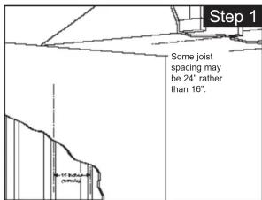
Locate the desired mounting position. Recommended minimum distance from the nearest wall is 20 inches for the PTC20 and 16" for the PTC13. Suggestions: avoid foot traffic areas and consider proximity of power and antenna connections.
Δ Hardware supplied for wood joist construction only! Hardware NOT intended for metal joist installation, please call us direct at 800-582-9595 for further instructions.
Δ This mount is only designed for use on flat ceilings, it will not work on angled or vaulted ceilings!

Use a stud sensor to locate the framing member (joist) near the desired mounting position for the ceiling mount. Using a sharp device (ie. drill bit or ice pick), penetrate the ceiling to identify the true center of the joist. The ceiling plate (C) will cover the holes that are made.
NOTE: The joist members are typically 1-1/2" wide and spaced 16" on center apart. Some joist spacing may be 24" rather than 16" on center.

Use the ceiling plate (C) as a template to mark four holes. Make sure to align the ceiling plate, so that the lag screw mounting holes lie in the center of the joist. Once the holes have been marked, drill four holes, 2-1/4" deep using a 5/32" drill bit. Slide an indexing washer (B) onto a platform bolt (A) and drop the platform bolt and indexing washer assembly through the center hole of the top (concave side) of the ceiling plate (C). Using the lag screws (J), mount the ceiling plate (C) to the ceiling. It is important that all four lag screws (J) are used and tightened down. This will prevent the heads of the lag screws from sticking out, interfering with the plastic cover and will insure the maximum holding strength of the unit.
Δ Caution: Drilling oversized holes may cause the lag screws (L) to pullout and undersized holes may cause breakage of lag screws (L) during installation.

Snap the plastic cover (D) in place over the ceiling plate (C).

Attach the steel frame to the ceiling plate by slipping the plate bolt (A) through the upper hole in the frame(G). Slide an indexing washer (B) onto the end of the "D" shaped bolt, then secure the steel frame in place by screwing a flange nut (H) snugly onto the "D" shaped bolt (A). Tighten the flange nut to desired swivel resistance. When unit is secure, insert dome cap (I) onto the bottom of the circular end of the steel frame (G) as shown in the illustration to the left.
Δ Note: If a VCR bracket is being used, refer to the VCR instructions before assembling the platform to the arm.
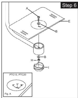
The platform for the PTC13 and the PTC20 has three hole positions to produce different degrees of angle (refer to Fig. A for the desired angle position). Using a platform bolt (A), an indexing washer (B) and a flange nut (H) attach the platform (E) to the circular end of the steel frame arm (G), as shown. Tighten the flange nut (H) to desired swivel resistance. CAREFUL! Do not over tighten nut, or the platform (E) will not rotate. When the platform is secure, insert dome cap (I) to the bottom portion of the circular end of the steel frame arm (G).
Brand : Vantage Point
Model : PTC20
Category : Ceiling TV Mount