
JDF-2S - Juicer Bunn - Free user manual and instructions
Find the device manual for free JDF-2S Bunn in PDF.


| Product Type | Commercial Juice Dispenser |
| Brand | Bunn |
| Model | JDF-2S |
| Power Requirements | 120V AC, 15A, 60Hz (or 220-230V AC, 15A) |
| Refrigerant | R134A, 10 oz (283 g) |
| Water Supply | Cold water, 20-100 psi (138-690 kPa), min 3 fl oz/sec (88.7 mL/sec) |
| Number of Dispense Stations | 2 |
| Dispense Control | Push-and-hold or programmable portion control |
| Portion Control | Yes, programmable per station (max 150 sec) |
| Cooling System | Ice bath with compressor and recirculation pump |
| Cabinet Temperature Range | 35-40°F (1.6-4.4°C) for concentrate storage |
| Ice Bank Formation | Automatic; takes several hours initially |
| Cleaning Frequency | Daily rinse and parts washing; monthly condenser filter cleaning |
| Sanitization Cycle | Semi-automatic or manual; uses Kay 5 sanitizer |
| Maintenance | Annual pump tubing replacement; check water level annually |
| Safety Features | Grounding required, circuit overload protection, CE compliant |
| Warranty | 2 years parts, 1 year labor (extended for electronic boards and compressor) |
| Weight (Estimated) | Approx. 120 lbs (54 kg) |
| Dispense Lockout Switch | Yes, to prevent unauthorized use |
| Program Switch | Yes, for setup and calibration |
Frequently Asked Questions - JDF-2S Bunn
User questions about JDF-2S Bunn
0 question about this device. Answer the ones you know or ask your own.
Ask a new question about this device
Download the instructions for your Juicer in PDF format for free! Find your manual JDF-2S - Bunn and take your electronic device back in hand. On this page are published all the documents necessary for the use of your device. JDF-2S by Bunn.
USER MANUAL JDF-2S Bunn
BUNN-O-MATIC CORPORATION
To ensure you have the latest revision of the Operating Manual, or to view the Illustrated Parts Catalog, Programming Manual, or Service Manual, please visit the Bunn-O-Matic website, at www.bunn.com. This is absolutely FREE, and the quickest way to obtain the latest catalog and manual updates. For Technical Service, contact Bunn-O-Matic Corporation at 1-800-286-6070.

BUNN-O-MATIC COMMERCIAL PRODUCT WARRANTY
Bunn-O-Matic Corp. ("BUNN") warrants equipment manufactured by it as follows:
1) Airpots, thermal carafes, decanters, GPR servers, iced tea/coffee dispensers, MCP/MCA pod brewers thermal servers and Thermofresh servers (mechanical and digital)- 1 year parts and 1 year labor.
2) All other equipment - 2 years parts and 1 year labor plus added warranties as specified below:
a) Electronic circuit and/or control boards - parts and labor for 3 years.
b) Compressors on refrigeration equipment - 5 years parts and 1 year labor.
c) Grinding burrs on coffee grinding equipment to grind coffee to meet original factory screen sieve analysis - parts and labor for 4 years or 40,000 pounds of coffee, whichever comes first.
These warranty periods run from the date of installation BUNN warrants that the equipment manufactured by it will be commercially free of defects in material and workmanship existing at the time of manufacture and appearing within the applicable warranty period. This warranty does not apply to any equipment, component or part that was not manufactured by BUNN or that, in BUNN's judgment, has been affected by misuse, neglect, alteration, improper installation or operation, improper maintenance or repair, non periodic cleaning and descaling, equipment failures related to poor water quality, damage or casualty. In addition, the warranty does not apply to replacement of items subject to normal use including but not limited to user replaceable parts such as seals and gaskets. This warranty is conditioned on the Buyer 1) giving BUNN prompt notice of any claim to be made under this warranty by telephone at (217) 529-6601 or by writing to Post Office Box 3227, Springfield, Illinois 62708-3227; 2) if requested by BUNN, shipping the defective equipment prepaid to an authorized BUNN service location; and 3) receiving prior authorization from BUNN that the defective equipment is under warranty.
THE FOREGOING WARRANTY IS EXCLUSIVE AND IS IN LIEU OF ANY OTHER WARRANTY, WRITTEN OR ORAL, EXPRESS OR IMPLIED, INCLUDING, BUT NOT LIMITED TO, ANY IMPLIED WARRANTY OF EITHER MERCHANTABILITY OR FITNESS FOR A PARTICULAR PURPOSE. The agents, dealers or employees of BUNN are not authorized to make modifications to this warranty or to make additional warranties that are binding on BUNN. Accordingly, statements by such individuals, whether oral or written, do not constitute warranties and should not be relied upon.
If BUNN determines in its sole discretion that the equipment does not conform to the warranty, BUNN, at its exclusive option while the equipment is under warranty, shall either 1) provide at no charge replacement parts and/or labor (during the applicable parts and labor warranty periods specified above) to repair the defective components, provided that this repair is done by a BUNN Authorized Service Representative; or 2) shall replace the equipment or refund the purchase price for the equipment.
THE BUYER'S REMEDY AGAINST BUNN FOR THE BREACH OF ANY OBLIGATION ARISING OUT OF THE SALE OF THIS EQUIPMENT, WHETHER DERIVED FROM WARRANTY OR OTHERWISE, SHALL BE LIMITED, AT BUNN'S SOLE OPTION AS SPECIFIED HEREIN, TO REPAIR, REPLACEMENT OR REFUND.
In no event shall BUNN be liable for any other damage or loss, including, but not limited to, lost profits, lost sales, loss of use of equipment, claims of Buyer's customers, cost of capital, cost of down time, cost of substitute equipment, facilities or services, or any other special, incidental or consequential damages.
392, A Partner You Can Count On, Air Infusion, AutoPOD, AXIOM, BrewLOGIC, BrewMETER, Brew Better Not Bitter, BrewWISE, BrewWIZARD, BUNN Espress, BUNN Family Gourmet, BUNN Gourmet, BUNN Pour-O-Matic, BUNN, BUNN with the stylized red line, BUNNlink, Bunn-OMatic, Bunn-O-Matic, BUNNserve, BUNNSERVE with the stylized wrench design, Cool Froth, DBC, Dr. Brew stylized Dr. design, Dual, Easy Pour, EasyClear, EasyGard, FlavorGard, Gourmet Ice, Gourmet Juice, High Intensity, iMIX, Infusion Series, Intellisteam, My Café, Phase Brew, PowerLogic, Quality Beverage Equipment Worldwide, Respect Earth, Respect Earth with the stylized leaf and coffee cherry design, Safety-Fresh, savemycoffee.com, Scale-Pro, Silver Series, Single, Smart Funnel, Smart Hopper, SmartWAVE, Soft Heat, SplashGard, The Mark of Quality in Beverage Equipment Worldwide, ThermoFresh, Titan, trifecta, Velocity Brew, Air Brew, Beverage Bar Creator, Beverage Profit Calculator, Brew better, not bitter., BUNNSource, Coffee At Its Best, Cyclonic Heating System, Daypart, Digital Brewer Control, Element, Milk Texturing Fusion, Nothing Brews Like a BUNN, Pouring Profits, Signature Series, Sure Tamp, Tea At Its Best, The Horizontal Red Line, Ultra are either trademarks or registered trademarks of Bunn-O-Matic Corporation. The commercial trifecta® brewer housing configuration is a trademark of Bunn-O-Matic Corporation.
CONTENTS
Warranty 2
User Notices 3
Initial Set-Up & Electrical Requirements 4
Plumbing Requirements 4
CE Requirements 4
Door Cover Installation 5
Plumbing Hookup 6
Initial Fill 6
Loading....15
Priming 15
Operating Controls 8
Dispenser Use....10
Portion Control Option....10
Cleaning....12
Adjustments & Optional Settings....14
Function Lists 18
Troubleshooting 20
Coolant Diagram 26
Schematic Wiring Diagram 27
Quick Setup Guide 29
USER NOTICES
Carefully read and follow all notices on the equipment and in this manual. They were written for your protection. All notices are to be kept in good condition. Replace any unreadable or damaged labels.
As directed in the International Plumbing Code of the International Code Council and the Food Code Manual of the Food and Drug Administration (FDA), this equipment must be installed with adequate backflow prevention to comply with federal, state and local codes. For models installed outside the U.S.A., you must comply with the applicable Plumbing/Sanitation Code for your area.
00656.0001
| WARNING | AVERTISSEMENT |
| ·DO NOT OVERLOAD CIRCUIT.· ALWAYS ELECTRICALLY GROUND THE CHASSIS.·DO NOT DEFORM PLUG OR CORD.· FOLLOW NATIONAL AND LOCAL ELECTRICAL CODES.· KEEP COMBUSTIBLES AWAY. | ·NE PAS SURCHARGER LE CIRCUIT.·TOUJOURS NETTRE LE BOFTIER À LA MARRIE.·NE PAS DEFORMER LA PICHE OU LE CORDION.·SE CONFORMER AUX CODES NATIONAL OU LOCAL D'ÉLECTRICIE.·GARDER LES PRODUITS COMBUSTIBLES À DISTANCE. |
| FAILURE TO COMPLY RISKS EQUIPMENT DAMAGE, FIRE OR SHOCK HAZARD. | TOUT MANUOEMENT À BE CONFORMER À CES DIRECTIVES PEUT ENTRARER DES DOMINAGES À L'ÉQUIPENT OU PRODUIT DES DANGERS D'INCENDIE OU D'ÉLECTROCUTION. |
| READ THE ENTIRE OPERATING MANUAL INCLUDING THE LIMIT OF WARRANTY AND LIABILITY BEFORE BUYING OR USING THIS PRODUCT. | VEULLEZ LRE LE MANUEL DE FONCTIONEMENT EN ENTER, Y COMPRIS LES LIMITES DE GARANTES ET RESPONSABLES AVANT D'ACHETER OU D'UTILISER LE PRESENT PRODUIT. |
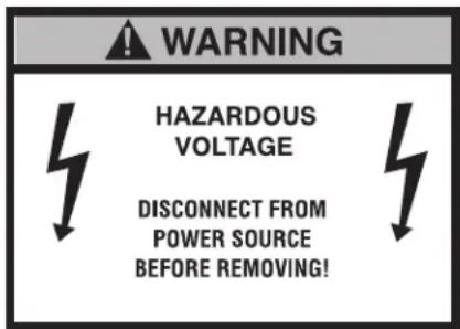
| THIS EQUIPMENT IS ENERGIZED AT ALL TIMES UNLESS ELECTRICALLY DISCONNECTED. | L'ÉQUIPEMENT EST TOUJOURS SOUS TENSION LORSQUIL NEST PAS DÉRANCIE. |
00986.7000
CHARGE
Type R134A, Amount 10 oz (283 gm)
Design Pressures:
High 335 psi (23 bar) (2.31 MPa)
Low 88 psi (6 bar) (0.61 MPa)
33461.0000
JDF-4S
12559.0003
CAUTION: The dispenser is very heavy! Use care when lifting or moving it. Use at least two people to lift or move the dispenser. Place dispenser on a sturdy counter or shelf able to support at least 150 lbs. (68 kg). This dispenser is designed for indoor use only.
Set the dispenser on the counter where it will be used. This dispenser requires a minimum of 4 inches (102 mm) of air clearance at the rear and 8 inches (203 mm) of air clearance above the dispenser. Minimal clearance is required between the dispenser sides and the wall or another appliance. For optimum performance, do not let warm air from surrounding machines blow on the dispenser. Leave some space so the dispenser can be moved for cleaning.
CE REQUIREMENTS
- This appliance must be installed in locations where it can be overseen by trained personnel.
- For proper operation, this appliance must be installed where the temperature is between 5^ to 35^ .
- Appliance shall not be tilted more than 10^ for safe operation.
- An electrician must provide electrical service as specified in conformance with all local and national codes.
- This appliance must not be cleaned by water jet.
- This appliance is not intended for use by persons (including children) with reduced physical, sensory or mental capabilities, or lack of experience and knowledge, unless they have been given instructions concerning use of this appliance by a person responsible for its safety.
- Children should be supervised to ensure they do not play with the appliance.
- If the power cord is ever damaged, it must be replaced by the manufacturer or authorized service personnel with a special cord available from the manufacturer or its authorized service personnel in order to avoid a hazard.
- Machine must not be immersed for cleaning.
ELECTRICAL REQUIREMENTS
CAUTION: The dispenser must be disconnected from the power source until specified in Electrical Hook-Up.
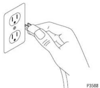
The 120V rated dispensers have an attached cord set and require a 2-wire, grounded, individual branch circuit rated 120 volts ac, 15 amp, single phase, 60Hz. The mating connector must be a NEMA 5-15R.
The 220-230V rated dispenser has an attached cord set and requires an attachment plug cap rated at least 230 volts ac, 15 amp. The attachment plug cap must meet with applicable national/local electrical codes.
Refer to the data plate for exact electrical requirements.
ELECTRICAL HOOK-UP
CAUTION: Improper electrical installation will damage electronic components.
- An electrician must provide electrical service as specified.
- Using a voltmeter, check the voltage and color coding of each conductor at the electrical source.
- Confirm that the refrigeration switch near the main control board is in the OFF position.
- Connect the dispenser to the power source.
- If plumbing is to be hooked up later, be sure the dispenser is disconnected from the power source. If plumbing has been hooked up, the dispenser is ready for Initial Fill.
PLUMBING REQUIREMENTS
This dispenser must be connected to a COLD WATER system with operating pressure between 20 and 100 psi (138 and 690 kPa). This water source must be capable of producing a minimum flow rate of 3 fluid ounces (88.7 milliliters) per second. A shut off valve should be installed in the line before the dispenser. Install a regulator in the line when pressure is greater than 100 psi (690 kPa) to reduce it to 50 psi (345 kPa). The regulator is also necessary if the water source has pressure fluxuations. The main water inlet is a 3/8" (9.52 mm) MFL connection.
NOTE- At least 18 inches (457 mm) of an FDA approved flexible beverage tubing, such as reinforced braided polyethylene, before the dispenser will facilitate movement to clean the countertop. It can be purchased direct from BUNN-O-MATIC (part number 34325.10__ [see Illustrated Parts Catalog for complete part number.]) BUNN-O-MATIC does not recommend the use of saddle valves to install the dispenser. The size and shape of the hole(s) made in the supply line(s) by saddle valves may restrict water flow.
As directed in the International Plumbing Code of the International Code Council and the Food Code Manual of the Food and Drug Administration (FDA), this equipment must be installed with adequate backflow prevention to comply with federal, state and local codes. For models installed outside the U.S.A., you must comply with the applicable Plumbing /Sanitation Code for your area.
DOOR COVER INSTALLATION
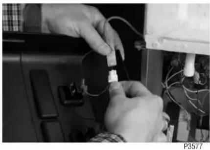
- Install door cover by first plugging the door harness connector into the machine harness connector located at the bottom of the machine door.

natural_image
Close-up of hands connecting a small electronic component to a cable (no visible text or symbols)JDF-2S
P3577
- On Portion Control models, connect membrane switches to Door Circuit Board.
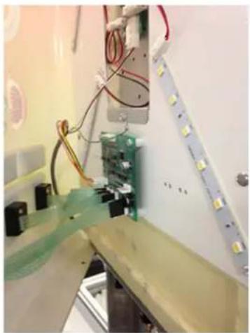
natural_image
Interior view of a laboratory or lab setup with electronic equipment and wiring (no visible text or symbols)JDF-4S Shown
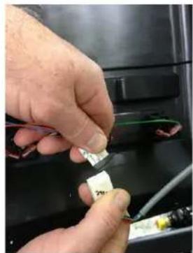
natural_image
Close-up of hands installing a small electronic component with wires, no visible text or symbolsJDF-4S
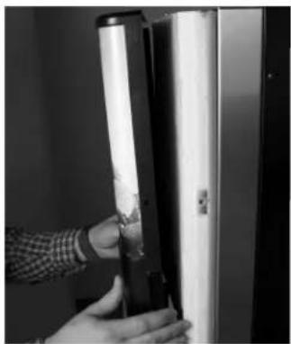
- Install door cover
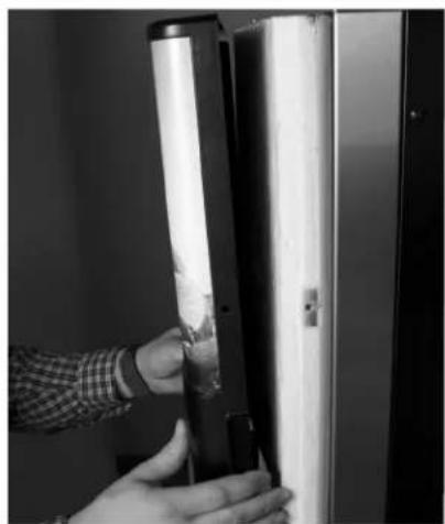
natural_image
Close-up of a hand holding a cylindrical object with a white panel, next to a black panel (no visible text or symbols)JDF-2S & JDF-4S
P3578
- Secure the door cover using 5 screws provided.
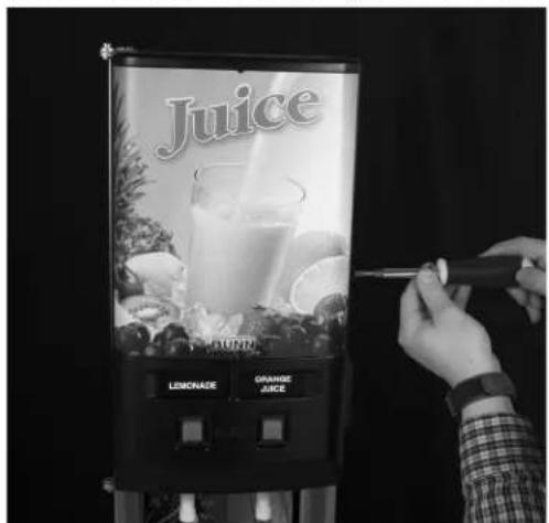
JDF-2S
P3579
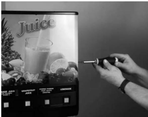
JDF-4S
P3840
PLUMBING HOOKUP
The plumbing connection is located on the rear of the dispenser. A 3/8" (9.52 mm) male flare adapter fitting is supplied, installed on the rear of the dispenser.
NOTE - Water pipe connections and fixtures directly connected to a potable water supply shall be sized, installed and maintained in accordance with federal, state and local codes.
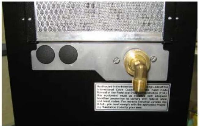
FIG 1 Plumbing Connections - JDF-2S
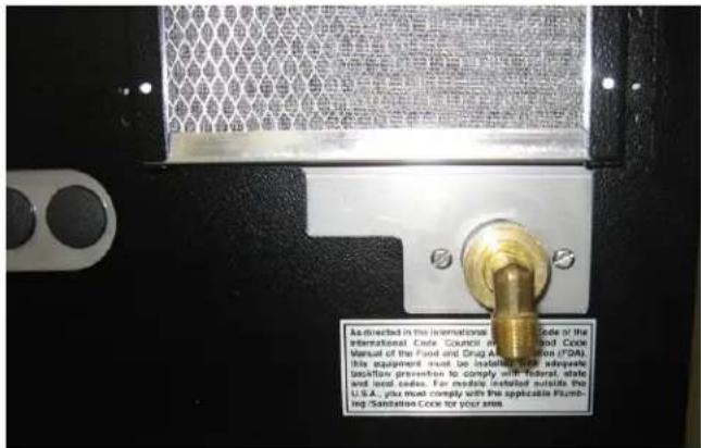
FIG 2 Plumbing Connections - JDF-4S
INITIAL FILL
CAUTION: The dispenser must be disconnected from the power source throughout the initial fill except when specified in the instructions.
- Remove drip tray assembly and splash panel from the dispenser. Replace the drip tray.
- Connect the water source to the back of the dispenser.
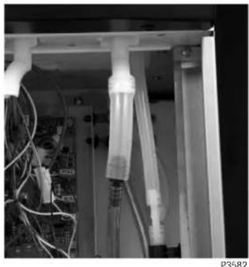
- Pull the fill tube from the dispenser, remove the plug and connect it to the dispense nozzle (Fig. 5 & 6).
- Set the Program Switch (Fig. 7) to the ON position. (On older models without program switch, set the Dispense Lockout Switch (Fig. 13) to the OFF position)
- Connect dispenser to the power source. Press and hold the dispense button for the dispense station that the tube is connected to for 10 seconds, until you hear the water valve turn on. (For Portion Control machines, press and hold the PLUS/STOP switch)
- Monitor the water bath fill level until water starts to trickle from the overflow tube. Then press the dispense button again to stop the fill process.
NOTE: The fill timer may time out before filling is complete. Press and hold the dispense button for 10 seconds to start again if needed.
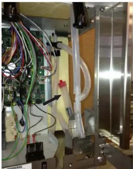
natural_image
Interior view of a laboratory apparatus with electronic components and wiring (no visible text or symbols)FIG 3 Initial Fill Hose - JDF-2S
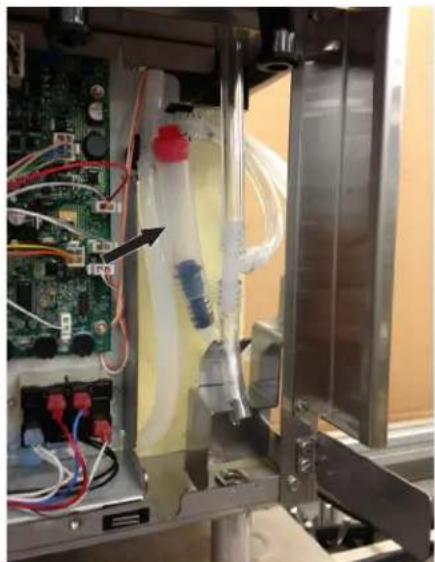
natural_image
Interior view of a medical or laboratory setup with visible tubing, wires, and electronic components (no text or symbols)FIG 4 Initial Fill Hose - JDF-4S
INITIAL FILL (Continued)
-
Turn ON the refrigeration switch near the main control board (Fig. 7). This will start the water bath pump circulation.
-
Check water level in the overflow tube and top off the tank if necessary (Step 5).
-
Disconnect the fill tube and allow excess water to drain into the drip tray. Replace the plug in the end of the fill tube and store back into the dispenser.
-
Set the Program Switch (near main control board) to the OFF position. (On older models without program switch, set the Dispense Lockout Switch to the ON position)
-
Replace the splash panel and drip tray.
-
It will take several hours to create the ice bank required for full dispenser performance. During this time, some further trickling from the water bath is expected due to expansion caused by ice bank formation. While the refrigeration system is creating the ice bank, the dispenser may be readied for use as described in Loading, Priming and Adjustment.
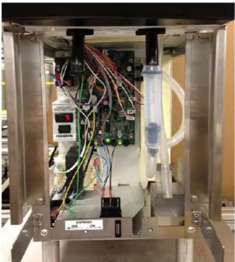
natural_image
Interior view of a laboratory apparatus with electronic equipment and wiring, no visible text or symbolsFIG 5 Initial Fill Connection - JDF-2S
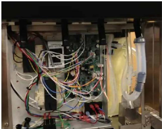
natural_image
Interior view of a medical or laboratory setup with colored wires, tubing, and electronic components (no visible text or symbols)FIG 6 Initial Fill Connection - JDF-4S
OPERATING CONTROLS
Refrigeration Switch
The refrigeration switch is located on the Electrical Panel of the dispenser near the Circuit Board. This switch controls power to the water bath pump and relay contacts for the compressor and condenser fan motor.
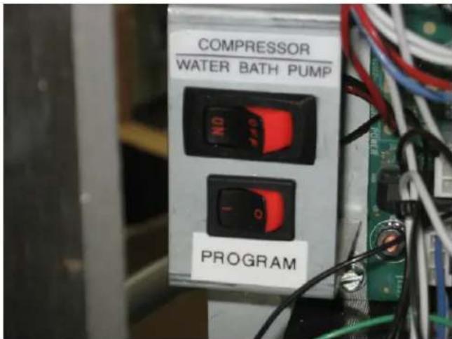
FIG 7 Refrigeration Switch
Product Dispense Switch (Mechanical Switch Machines)
Pressing and holding switch will initiate product flow from the respective nozzle; releasing the switch will stop the flow.
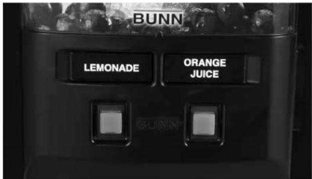
FIG 9 Product Dispense Switches - JDF-2S
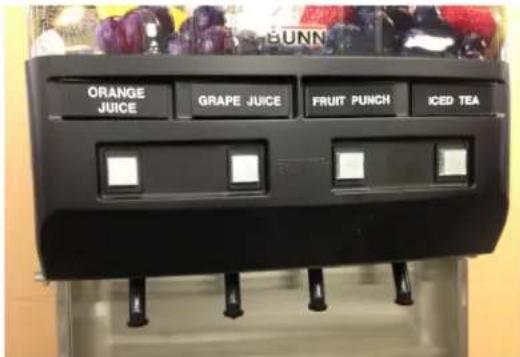
FIG 10 Product Dispense Switches - JDF-4S
OPERATING CONTROLS (Continued)
Product Dispense Switch (Membrane Switch Machines)
A. Product Dispense Switch
Momentarily pressing and releasing one of the switches will initiate a timed dispense. Each station has three different timed dispenses which are preset at the factory. Refer to DISPENSER USE section for preset volumes and adjustment procedures.
B. Plus/Stop Switch
This switch can be used to "top-off" a beverage. Pressing and holding switch will initiate product flow from the respective nozzle; releasing the switch will stop the flow. Momentarily pressing this switch during a timed dispense will stop the flow.
C. Chilled Water Dispense Switch (Optional for JDF-4S only)
Pressing and holding switch will initiate chilled water flow from the nozzle; releasing the switch will stop flow.
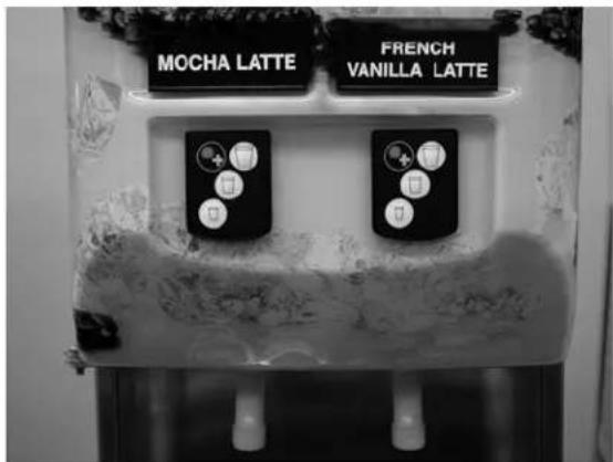
FIG 11 Product Dispense Switches - JDF-2S
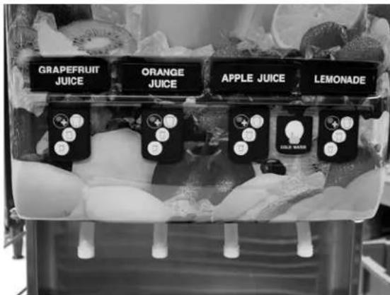
FIG 12 Product Dispense Switches - JDF-4S
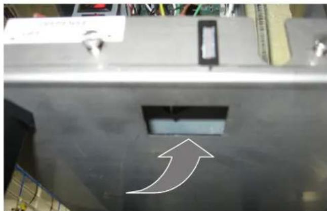
Dispense Lockout Switch
This switch is located at the bottom front of the dispenser just behind the drip tray. It is used to turn ON and OFF the Dispensing function. It is also used for some programming and fill procedures.
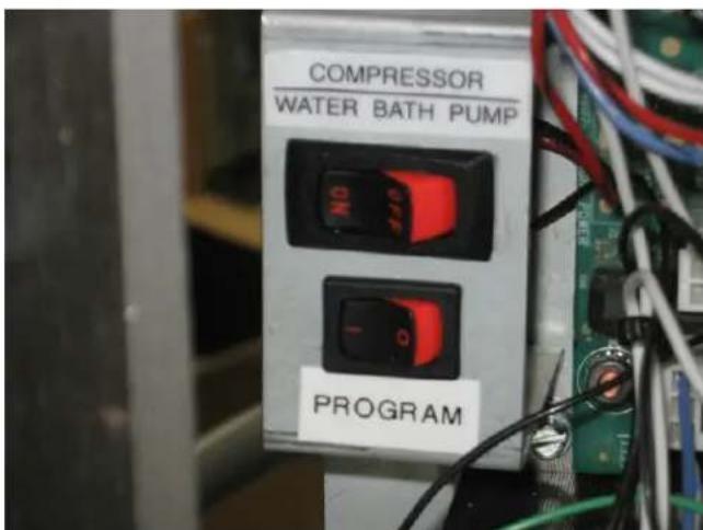
FIG 14 Program Switch
natural_image
Close-up of a metallic mechanical component with a white arrow pointing upward, no visible text or symbolsFIG 13 Dispense Lockout Switch
Program Switch
This switch is located near the main control board next to the refrigeration switch.
OPERATING CONTROLS (Continued)
DISPENSER USE
Press and Hold Dispensing:
- Place a cup on the drip tray beneath the desired dispensing nozzle.
- Press and hold the "Product Dispense" switch until the beverage reaches the desired level, then release.
Portion Control Option (Mechanical Switch Machines)
The dispenser is also equipped with a portion control option. The following steps will guide you through the set up process for this option. Portion control can be set on one or all dispense heads as needed.
- Unplug dispenser from power source.
- Set the Program Switch (near main control board) to the ON position. (On older models without program switch, set the Dispense Lockout Switch to the OFF position)
- Remove drip tray and splash panel from the front of the machine then replace the drip tray.
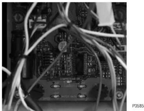
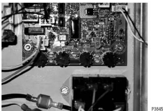
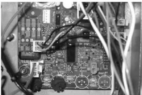
- Press and hold the left most (Station 1) dispense switch while plugging the dispenser into the power source. Continue holding dispense switch(s) until all 4 temperature LED's, Figs. 15 and 16 on the circuit board start flashing slowly (this takes about 5 seconds). Release dispense switch(s).
- Press and release any dispense switch 6 times to enter the portion control set up mode. This will cause the 4 temperature LED's to flash rapidly.
- Place a container under the desired dispense nozzle to measure the portion size.
- Press and hold the desired dispense switch to dispense product until the desired amount of product is achieved. (Maximum dispense time is 150 seconds). Repeat this on all dispense heads as desired.
- Set the Program Switch (near main control board) to the OFF position. (On older models without program switch, set the Dispense Lockout Switch to the ON position)
- Place a container under the dispense nozzle(s) and press the dispense button to confirm that the portion size is set correctly. Repeat steps 1-8 if any changes are needed.
- Replace splash panel.
Note: The portion control dispense can be cancelled during a dispense by pressing the dispense button again. Note: If a portion size is not set for a dispense head while in the portion control set up mode, that dispense head will remain a push and hold dispense head.
Push and Hold Membrane Switch Machines
- To set single portion sizes on a push and hold membrane type dispense switch, follow steps 1 - 10 above.
Portion Control Option (Membrane Switch Machines)
Portion sizes are preset but can be adjusted by following these steps below.
- Set the Program Switch (near main control board) to the ON position. (On older models without program switch, set the Dispense Lockout Switch to the OFF position)
- Press and hold the large and medium buttons on the left most (Station #1) dispense station until you hear the machine "beep" three times.
- Place a measuring container under the station to be adjusted, then press and hold the appropriate dispense switch until the desired amount is dispensed. The machine will record the amount of time that the button is pressed continuously. If the button is released too soon, simply empty the container and start over.
- Repeat step 3 for all stations as desired.
- Turn the program switch to the OFF position.
OPERATING CONTROLS (Continued)
Procedure to return all dispense heads back to Push and Hold mode (Mechanical Switch Machines):
- Unplug dispenser from power source.
- Place Program switch in the ON position.
- Remove drip tray and splash panel from the front of the machine then replace the drip tray.
- For the JDF-2S, press and hold either dispense switch while plugging the dispenser into the power source. For the JDF-4S, press and hold two left dispense switches while plugging the dispenser into the power source. Continue holding dispense switch(s) until all 4 temperature LED's on the circuit board start flashing slowly (this takes about 5 seconds). Release dispense switch(s).
- Press and release any dispense switch three times.
- Place Program switch back into the OFF position.
- Replace splash panel and drip tray.
- Place a container under each dispense nozzle and press dispense buttons to confirm machine is operating in push and hold mode.
natural_image
Close-up of an electronic circuit board with visible traces and components (no readable text or symbols)FIG 15 Temperature LEDs JDF-2S (Early Models)
natural_image
Close-up of an electronic circuit board with visible components and wiring (no readable text or symbols)FIG 16 Temperature LEDs JDF-4S
natural_image
Close-up of an electronic circuit board with visible traces and components (no readable text or symbols)FIG 15A Temperature LEDs JDF-2S (Late Models)
CLEANING & PREVENTIVE MAINTENANCE
Daily: Rinse Procedure
Tools required: 32 oz. (946 ml) minimum empty container
- Open dispenser door. Lift up on product containers and remove them from the machine.
- Close the door, place an empty container under the dispensing nozzle.
- Dispense from each station until clear water flows from the dispense nozzle.
- Open dispenser door and reconnect all product containers.
Daily: Parts Washing
- Remove and wash the dispense nozzle(s), drip tray and drip tray cover in a mild detergent solution. Rinse thoroughly. Use brush (00674.0000) to clean inside and oring area on dispense nozzles.
- Wipe splash panel, areas around dispense nozzle(s), and refrigerated compartment with a clean, damp cloth.
- Use brush and a mild detergent solution to clean inside dispense area where dispense nozzles are removed. Rinse.
Sanitize Process for Semi-Automatic and Manual
Tools required: 1 empty 5 gallon (18.9 L) bucket, 2 packets of Kay 5 sanitizer, and clean, empty concentrate container.
- Remove all concentrate from the dispenser and store in a separate refrigerated compartment.
- Fill clean empty concentrate container(s) with approximately 32 oz. (946 ml) of hot tap water (approximately 140 Deg. F (60 Deg. C). Load the containers of hot water into the dispenser (just like concentrate).
- Place an empty container under the dispense nozzles.
- Press and hold the dispense button at each station until the stream out of the nozzles runs clear (about 30 seconds). Note: the dispenser will not allow all stations to run at the same time.
- Once this is completed, remove the container(s) and empty.
- Remove each dispense nozzle and mixing element and run under hot tap water to remove excess pulp.
- Prepare 2.5 gal. (9.46 L) of sanitizing solution by dissolving 1 packet of Kay 5 sanitizer into 2.5 gal. (9.46 L) of 120 Deg F (48.9 Deg. C) water to ensure 100 ppm of available chlorine.
- Place nozzle(s) and mixing element(s) in a separate 1-quart container of sanitizing solutions and mix thoroughly. Allow the parts to soak for 2 minutes.
- Clean the dispense nozzle receptacle(s) (dispense valves) with the sanitizing solution and a soft bristle brush.
- Clean the concentrate bottle's inlet adapter(s) using the sanitizing solution and a soft bristle brush.
- Replace the mixing element(s) and nozzle(s).
- Fill approximately 128 ounces (3.8 L) of clean sanitizing solution into clean, empty concentrate container(s). Do not use the sanitizing solution used in step 10. Load the container(s) into the dispenser.
- Place the empty 5 gallon bucket under the dispense nozzles.
For Semi-Automatic Sanitizing Prior to S/N JDF0016500:
- a. For the JDF-2S, press and hold both dispense buttons for about 10 seconds to initiate the sanitize cycle. b. For the JDF-4S, press and hold three left most dispense buttons (Stations 1, 2 and 3) for about 10 seconds to initiate the sanitize cycle. The cycle will start with only one of the dispense stations dispensing. Note: The cycle will consist of a 1 minute dispense time (alternating) on each station, then 5 minutes of soak time, then a 2 minute dispense time (alternating) on each station.
For Semi-Automatic Sanitizing Effective S/N JDF0016500 and up:
- Turn the Program Switch in the bottom of the machine to the "ON" position.
a. For the JDF-2S, press the left dispense button 2 times, then press the right dispense button 2 times.
b. For the JDF-4S, press the left most (station 1) dispense button 2 times, then the left center (station 2) button 2 times. The cycle will start with only one of the dispense stations dispensing. Note: The cycle will consist of a 1 minute dispense time (alternating) on each station, then 5 minutes of soak time, then a 2 minute dispense time (alternating) on each station.
For Manual Sanitizing:
- a. Dispense each station for 1 minute.
b. Allow to soak for 5 minutes.
c. Dispense each station for 2 minutes.
NOTE: On Portion Control models, use the plus/stop switches.
-
When the above cycle is complete, Remove the sanitizing solution and replace with concentrate.
-
At each station, press and hold the dispense switch until product appears. Then dispense one 12 ounce (354.9 ml) glass of finished product and discard.
-
Wipe internal and external surfaces with a clean, damp cloth.
CLEANING (cont)
Monthly: Clean Condenser Coils and Filter
- Removable filter can be cleaned in warm soapy water.
- Use a soft bristle brush to clean the build up of dirt in the condenser.
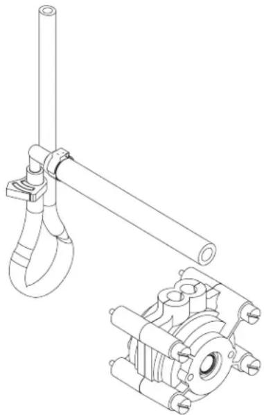
Annually: Check water level in ice bath. Top off if needed. Annually: Replace Pump Tubing
39690.0000 Tube Kit JDF-2S & JDF-4S
39688.0000 Tube Assembly
natural_image
Technical line drawing of a mechanical assembly with no visible text or symbols- Open dispenser door.
- Remove all product containers and place them in a refrigerated (35-40 degrees F [1.6-4.4 degrees C]) environment. Disconnect all connections to ambient products from the bottle adapter.
- Rinse all dispense stations using steps outlined in "DAILY RINSE PROCEDURE".
- Disconnect dispenser from power source.
- Remove the dispense platform cover.
- Disconnect the dispense platform water line(s) from the supply line inside the refrigerated cabinet and disconnect the wiring connection(s) from the cabinet receptacle(s).
- Remove the mounting screw(s) securing the dispense platform(s) to the cabinet.
- Pull the dispense platform(s) completely out of the cabinet and place it on a flat work surface.
- Close the dispenser door.
- Remove the 4 screws securing the pump head.
- Gently pull the pump head apart.
- Gently pull the pump tube from around the pump's rotor.
- Release the clamps securing the old pump tubing to the plastic elbows.
- Pull the plastic elbows from the old pump tubing, and discard the old pump tubing.
- Insert the plastic elbows into the new pump tubing and secure it with the clamps.
- Gently wrap the new pump tubing around the pump's rotor.
- Reassemble the pump housing onto the platform assembly.
- Repeat steps 10 through 17 for the remaining pump(s).
- Replace the dispense platform(s) into the refrigerated cabinet, making sure to reconnect all electrical and water connections.
- Replace the dispense platform cover.
- Turn power on to dispenser.
22 Install containers of rinse water, run each station and check for leaks. Repair leaks as necessary. - Replace product shelf and product containers. Reconnect any connections to ambient product containers.
- Prime the pumps as described in "PRIMING" in the Initial Fill Section.
ADJUSTMENT & OPTIONAL SETTINGS
Water Flow Testing and Adjustment
NOTE: Purge all dispense stations to remove air from water line before making initial adjustments.
- Place a graduated measuring cup or the large chamber of the empty brixing cup (BUNN-O-MATIC part number 33095.0000) under the appropriate dispense nozzle. Place the Program switch in the ON position.
- Press and release the desired "Product Dispense Switch" three times.(On Portion Control models, use the plus/stop switches)
- The selected position will dispense water (no concentrate) only for 3 seconds.
- Measure the water dispensed. Suggested target is 3 ounces (1 ounce per second flow rate.
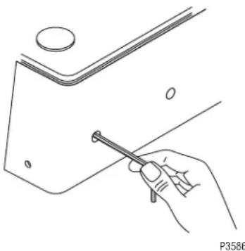
- Adjust the water flow rate Fig 17, (clockwise to increase flow rate; counterclockwise to decrease flow rate) to the corresponding product mix ratio. Chart below provides general brix instructions.
natural_image
Line drawing of a hand holding a pen, with a small circular object above and a diagonal line below (no text or symbols)FIG 17 Adjusting Water Flow Using 1/4" allen wrench
| Mix Ratio Adjust water flow rate to: Product Brix %(water + concentrate) | |||
| 2+1 *3.0 fl. oz (89 ml) Prune per 3-second test Other * | Juice 16.0% | ||
| Orange Juice 11.8%4+1Cranberry Fruit Cocktail 14.0%*3.0 fl. oz (89 ml) Grapefruit Juice per 3-second test5+1Fruit PunchGrape Juice 13.0% | Pineapple Juice 12.8% | ||
| 10.6% | |||
| Lemonade | |||
| Apple Juice 12.0% | |||
| 3+1 through 7+1 | Other * | ||
| Above 7+1per 3-second test | *4.0 fl. oz (118 ml) | Other | * |
| High Viscosity Juiceper 3-second test | 3.0 fl. oz (89 ml) | As Required | - |
*Maximum flow rate may be less depending on the water pressure supply at each location.
Note: Information for specific products listed in this table is to be used for reference only. Consult the product label for exact mix ratio and/or brix %. See product label for target brix %.
6. Repeat steps 1 through 5 as necessary until the correct water flow rate is achieved.
7. Repeat steps 1 through 5 for the remaining dispense positions.
8. Place the Program switch back into the OFF position.
Pump Speed Adjustment
- Disconnect the dispenser from the power source.
- Remove the drip tray.
- Remove the two screws securing the splash panel and remove the splash panel
- Locate the adjustment knobs on the circuit board.
NOTE: Start with the adjustment dial in the nine o'clock position.
- Turn the adjustment knobs clockwise to increase speed and counterclockwise to decrease speed.
NOTE: If splashing occurs while dispensing, reduce water flow rate. Then re-adjust pump speed to achieve proper ratio/brix target.
- The knob positions directly correspond to dispense station locations.
NOTE: Some 2S models have 4 adjustment knobs on the circuit board. For these models use the two left most knobs to make pump speed adjustments. Left most being station #1 (left side dispense) and left center being station #2 (right side dispense).
- Reinstall the splash panel and drip tray and reconnect the dispenser to the power source.
LOADING
Frozen Concentrates
- Thaw the frozen concentrate in a refrigerated 35-40 degrees F (1.6-4.4 degrees C) environment for 36 to 48 hours before use.
NOTE: Loading frozen concentrate in the product cabinet may cause damage to the machine. This damage is not covered by warranty.
- Thoroughly mix the thawed concentrate by vigorously shaking the product container.
- Open the dispenser door.
- Prior to placing the product container in the dispenser, make sure that the o-ring on the container adapter is lubricated. This will ease removal of the container when it becomes necessary.
- Place the product container in the desired position and press it firmly into the bottle adapter opening.
- Open the vent hole in the product container.
Note: Concentrate in the container must be completely thawed and be within the temperature range of 35-40 degrees F (1.6-4.4 degrees C.) Product outside of this temperature range, especially below, will produce an “out of brix” drink.
Ambient Concentrates (Optional)
- Install an Ambient Concentrate Conversion Kit (BUNN-O-MATIC part number 33699.0002) per the instructions provided in the kit.
- Attach the concentrate product hose to the appropriate concentrate line located at the rear of the dispenser.
- Attach the other end of the product hose to the product container through an appropriate fitting.
PRIMING
- Open the dispenser door
- Load concentrate per instructions in section titled Loading.
- Close the dispenser door.
- Place a large container under the appropriate dispense nozzle.
Press and hold the "Product Dispense Switch" Fig 5, until concentrate dispenses from the dispense nozzle.
Note: This may take several seconds, depending on the installation and set pump speed.
ADJUSTMENT & OPTIONAL SETTINGS (cont)
Total Dispense Ratio Set Up Procedure
- Adjust water flow as described in Water Flow Testing and Adjustment. Record water output setting for later reference on each dispense head. Suggested target is 3 ounces.
- Place the Program switch in the ON position.
- Place a measuring container under the dispense nozzle, press and release the DISPENSE button 6 times.
NOTE: For best results, discard the first sample and measure a second sample. Repeat the same practice after every adjustment. - Record the total ounces dispensed.
- Refer to the Brix/Ratio chart below to confirm proper total dispensed amount for ratio desired and water output previously recorded.
- To increase or decrease the product output, refer to Pump Speed Adjustment section.
- Place the Program switch back into the OFF position.
| 3 secondwater dispensein ounces | Ratio Target | ||||||||||||||
| 2:1 | 3:1 | 4:1 | 5:1 | 6:1 | 7:1 | 8:1 | 9:1 | 10:1 | 11:1 | 12:1 | |||||
| 1.5 | 2.25 | 2.00 | 1.88 | 1.80 | 1.75 | 1.71 | 1.69 | 1.67 | 1.65 | 1.64 | 1.63 | ||||
| 1.75 | 2.63 | 2.33 | 2.19 | 2.10 | 2.04 | 2.00 | 1.97 | 1.94 | 1.93 | 1.91 | 1.90 | ||||
| 2.0 | 3.00 | 2.67 | 2.50 | 2.40 | 2.33 | 2.29 | 2.25 | 2.22 | 2.20 | 2.18 | 2.17 | ||||
| 2.25 | 3.38 | 3.00 | 2.81 | 2.70 | 2.63 | 2.57 | 2.53 | 2.50 | 2.48 | 2.45 | 2.44 | ||||
| 2.5 | 3.75 | 3.33 | 3.13 | 3.00 | 2.92 | 2.86 | 2.81 | 2.78 | 2.75 | 2.73 | 2.71 | ||||
| 2.75 | 4.13 | 3.67 | 3.44 | 3.30 | 3.21 | 3.14 | 3.09 | 3.06 | 3.03 | 3.00 | 2.98 | ||||
| 3.0 | 4.50 | 4.00 | 3.75 | 3.60 | 3.50 | 3.43 | 3.38 | 3.33 | 3.30 | 3.27 | 3.25 | ||||
| 3.25 | 4.88 | 4.33 | 4.06 | 3.90 | 3.79 | 3.71 | 3.66 | 3.61 | 3.58 | 3.55 | 3.52 | ||||
| 3.5 | 5.25 | 4.67 | 4.38 | 4.20 | 4.08 | 4.00 | 3.94 | 3.89 | 3.85 | 3.82 | 3.79 | ||||
| 3.75 | 5.63 | 5.00 | 4.69 | 4.50 | 4.38 | 4.29 | 4.22 | 4.17 | 4.13 | 4.09 | 4.06 | ||||
| 4.0 | 6.00 | 5.33 | 5.00 | 4.80 | 4.67 | 4.57 | 4.50 | 4.44 | 4.40 | 4.36 | 4.33 | ||||
| 3 secondwater dispensein milliliters | Ratio Target | ||||||||||||||
| 2:1 | 3:1 | 4:1 | 5:1 | 6:1 | 7:1 | 8:1 | 9:1 | 10:1 | 11:1 | 12:1 | |||||
| 44.4 | 66.5 | 59.1 | 55.5 | 53.2 | 51.8 | 50.7 | 49.9 | 49.3 | 48.8 | 48.4 | 48.1 | ||||
| 51.8 | 77.6 | 69.0 | 64.7 | 62.1 | 60.4 | 59.1 | 58.2 | 57.5 | 56.9 | 56.5 | 56.1 | ||||
| 59.1 | 88.7 | 78.9 | 73.9 | 71.0 | 69.0 | 67.6 | 66.5 | 65.7 | 65.1 | 64.5 | 64.1 | ||||
| 66.5 | 99.8 | 88.7 | 83.2 | 79.8 | 77.6 | 76.0 | 74.9 | 73.9 | 73.2 | 72.6 | 72.1 | ||||
| 73.9 | 110.9 | 98.6 | 92.4 | 88.7 | 86.3 | 84.5 | 83.2 | 82.1 | 81.3 | 80.7 | 80.1 | ||||
| 81.3 | 122.0 | 108.4 | 101.7 | 97.6 | 94.9 | 92.9 | 91.5 | 90.4 | 89.5 | 88.7 | 88.1 | ||||
| 88.7 | 133.1 | 118.3 | 110.9 | 106.5 | 103.5 | 101.4 | 99.8 | 98.6 | 97.6 | 96.8 | 96.1 | ||||
| 96.1 | 144.2 | 128.1 | 120.1 | 115.3 | 112.1 | 109.8 | 108.1 | 106.8 | 105.7 | 104.8 | 104.1 | ||||
| 103.5 | 155.3 | 138.0 | 129.4 | 124.2 | 120.8 | 118.3 | 116.4 | 115.0 | 113.9 | 112.9 | 112.1 | ||||
| 110.9 | 166.4 | 147.9 | 138.6 | 133.1 | 129.4 | 126.7 | 124.8 | 123.2 | 122.0 | 121.0 | 120.1 | ||||
| 118.3 | 177.4 | 157.7 | 147.9 | 141.9 | 138.0 | 135.2 | 133.1 | 131.4 | 130.1 | 129.0 | 128.1 | ||||
ADJUSTMENT & OPTIONAL SETTINGS (cont)
Temperature Compensated Refractometer Method
- Adjust the water flow as described in Water Flow Testing and Adjustment.
- Place an empty container under the appropriate dispense nozzle.
- Press and hold the "Product Dispense Switch" Figs 9 & 10, until water and concentrate begin flowing freely from the dispense nozzle.
- Discard the product caught previously and place the empty container back under the dispense nozzle.
- Press and hold the "Product Dispense Switch" until the cup is filled.
- Stir the contents of the cup, and use the refractometer (according to the manufacturer's instructions) to check the brix %.
- Adjust the pump speed (down to decrease the brix %; up to increase the brix %) to achieve the correct brix % as described in Pump Speed Adjustment.
Optional Cold Water Flow Adjustment
Some dispensers are equipped with an optional cold water dispense valve. It is recommended to adjust the flow rate upon initial set up of the dispenser. The adjustment for the cold water can be located inside the dispenser behind the right service panel. The cold water dispense valve is mounted to the frame just above the ice bath. Attached to this valve is a needle type adjustment valve. Turn the adjustment clockwise to decrease the water flow, and counter-clockwise to increase the water flow.
Dispenser Lockout
Dispense functions of the dispenser can be turned-off to prevent unauthorized use of the dispenser, while keeping the refrigeration system running.
-
Locate the Dispense Lockout switch at the bottom front of the dispenser behind the drip tray.
-
Place the switch in the OFF position to prevent dispensing.
-
Place the switch in the ON position to allow dispensing.
NOTE: This switch will also operate the door lights on models equipped with this feature.
FUNCTION LIST
Circuit Board LED Indicators - JDF-2S (Early Models)
| LED # LED Color Illuminates: | ||
| 1 Green When the compressor should be ON. | ||
| 2 Cabinet Red When the cabinet temperature is above 50 degrees F. | ||
| Flashes slowly when cabinet temperature exceeds 50 degrees F for 4 hours. Dispense functions are locked out under this condition. Power down the dispenser to reset. | ||
| Flashes rapidly if dispense is attempted in lockout condition. | ||
| Open cabinet thermistor circuit will flash #2 and #3 LED's 1 time every 3 seconds. | ||
| Shorted cabinet thermistor will turn #2 and #3 LED's on steady.*This mode disables the cabinet low temperature lockout fault. | ||
| 3 Cabinet Green When cabinet temperature is below 50 degrees F. | ||
| 4 Bath | Red When bath temperature is above 34 degrees F. | |
| Flashes slowly when compressor is in a 6 minute delay period. | ||
| Open bath thermistor circuit will flash #4 and #5 LED's 1 time every 3 seconds. The compressor will not run under this condition. | ||
| Shorted bath thermistor circuit will flash #4 and #5 LED's 2 times every 3 seconds. The compressor will not run under this condition. | ||
| 5 Bath | Green When bath temperature is below 34 degrees F. | |
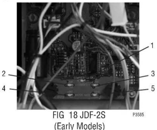
FUNCTION LIST (Continued)
Circuit Board LED Indicators - JDF-4S and Late Model JDF-2S
| LED # LED Color Illuminates | ||
| 1 Bath Red | When bath temperature is above 34 degrees F. | |
| Flashes slowly when compressor is in a 6 minute delay period. | ||
| Open bath thermistor circuit will flash #1 and #2 LED's 1 time every 3 seconds. The compressor will not run under this condition. | ||
| Shorted bath thermistor circuit will flash #1 and #2 LED's 2 times every 3 seconds. The compressor will not run under this condition. | ||
| 2 Bath Green When bath temperature is below 34 degrees F. | ||
| 3 Green When the compressor should be ON. | ||
| 4 Cabinet | Red | When the cabinet temperature is above 50 degrees F. |
| Flashes slowly when cabinet temperature exceeds 50 degrees F for 4 hours. Dispense functions are locked out under this condition. Power down the dispenser to reset. | ||
| Flashes rapidly if dispense is attempted in lockout condition. | ||
| Open cabinet thermistor circuit will flash #4 and #5 LED's 1 time every 3 seconds. | ||
| Shorted cabinet thermistor will turn #4 and #5 LED's on steady.*This mode disables the cabinet low temperature lockout fault. | ||
| 5 Cabinet | Green | When cabinet temperature is below 50 degrees F. |
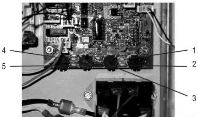
FIG 19 JDF-4S
TROUBLESHOOTING
A troubleshooting guide is provided to suggest probable causes and remedies for the most likely problems encountered. If the problem remains after exhausting the troubleshooting steps, contact the Bunn-O-Matic Technical Service Department.
- Inspection, testing, and repair of electrical equipment should be performed only by qualified service personnel.
- All electronic components have 120-240 volt ac and low voltage dc potential on their terminals. Shorting of terminals or the application of external voltages may result in board failure.
- Intermittent operation of electronic circuit boards is unlikely. Board failure will normally be permanent. If an intermittent condition is encountered, the cause will likely be a switch contact or a loose connection at a terminal or crimp.
- Solenoid removal requires interrupting the water supply to the valve. Damage may result if solenoids are energized for more than ten minutes without a supply of water.
- The use of two wrenches is recommended whenever plumbing fittings are tightened or loosened. This will help to avoid twists and kinks in the tubing.
- Make certain that all plumbing connections are sealed and electrical connections tight and isolated.
WARNING – • Exercise extreme caution when servicing electrical equipment.
- Unplug the dispenser when servicing, except when electrical tests are specified.
- Follow recommended service procedures.
- Replace all protective shields or safety notices.
PROBLEM
Cold Water Circulation
Dispense stations not working.
Note: Cooling failure or excessive cabinet temperatures for more than 4 hours will result in dispense lockout or no dispense.
Note: Reset fault/timer by unplugging unit.
Dispense nozzle dripping/won't stop dispensing.
PROBABLE CAUSE
- Cabinet cooling fan.
-
Bath recirculation pump.
-
Restricted water flow to cabinet water coil and bath.
-
Juice residue causing oring on dispense nozzle to lose vacuum.
-
Mechanical Switch Models- This may be caused by juice residue splashed or wiped onto switches.
-
Membrane Switch Models-
REMEDY
Replace fan (24vdc). Note: Fan receives power when the dispenser is powered.
A) If not running, check refrigeration switch and wiring for proper continuity.
B) Check for 120V or 230V AC at pump. Replace pump.
Check for kinked hose.
A) Remove dispense nozzle. Clean nozzles and oring in mild detergent solution.
B) Use soft bristle brush and mild detergent solution to clean dispense valve area that dispense nozzles are seated.
Clean or replace switches.
Check continuity of dispense switches. Replace as needed.
TROUBLESHOOTING (cont.)
| PROBLEM | PROBABLE CAUSE | REMEDY |
| RefrigerationDispense stations not working. Note: Cooling failure or excessive bath and cabinet temperatures for more than 4 hours will result in dispense lockout or no dispense. | 1. Compressor ON/OFF switch. | Check for "ON" position or no continuity - replace switch. |
| 2. Dirty condenser filter or fins. | Clean filter and fins or replace condenser filter. (Filter not supplied on some machines). | |
| 3. Condenser fan not running. | A) Check for 120V or 230V AC. Replace fan motor or check fan blades for obstructions. | |
| B) Check compressor LED on circuit board. If ON, relay coil should have power (120 or 230 VAC). | ||
| 4. Compressor relay not activating. | Check compressor relay coil for 120 or 230vac. NOTE: Always check power with coil attached. If compressor LED is ON and no 120 or 230vac - replace board. If yes, 120 or 230vac - replace relay. Note: Relay contacts are normally open. | |
| 5. Compressor not running. | Check compressor thermal overload (N/C). If open check for dirty condenser filter or adequate ventilation and space around machine. | |
| 6. Compressor running and not cooling. | Check refrigeration system for leaks and proper charge. | |
| Dispenser Locked OutDispense stations not working. | 1. Check Dispense Lockout switch. | (A) Set switch to ON position. |
| (B) Check switch and harness for proper continuity. | ||
| Cooling system failure. | 1. Refrigeration or cold water recirculation system. | Check all previous items that pre-tain to refrigeration or cold water recirculation |
| Dispense station not working | 1. Dispense Lockout switch set to OFF position. | Place switch in ON position. |
| 2. Dispense switch failed | Check switch and harness for proper continuity. | |
| All stations dispense concentrate only | Main water supply | Check for ON position. |
| Frozen bath | A) Compressor relay/contacts shorted - replace relay. | |
| B) Recirculating pump - replace or check for kinked flex line. | ||
| Inlet water valve failed | A) Check for 120V or 230V power when dispensing. If yes, replace valve. If no, check harness for proper continuity. Then replace circuit board if needed. | |
| Dispense station concentrate only | Water solenoid | Replace solenoid (24vdc) or check wire connection between water valve and main control board. |
| Dispense station water only | Concentrate out | Replace refill concentrate container or BIB |
| Product pump not pumping | Check for proper counterclockwise rotation of pump rollers. If counterclockwise, replace pump tubing. If clockwise, wire connection to pump is reversed. Switch wires on terminals. | |
| Pump not turning | A) Check speed setting on circuit board and increase speed (turn clockwise) | |
| B) Check for d.c. power to pump motor. If yes, replace motor assy. If no, check harness for proper continuity. Then replace circuit board if needed. | ||
| Water leak filling drip tray or around dispense deck area | 1. Initial fill/setup | Some expansion normal. May fill drip tray during initial ice block formation |
| 2. Dispense deck | Inspect or replace fittings clamps, o-rings, solenoids and quick disconnect fittings.NOTE: Dispense deck area slopes to drain tube that leads to the drip tray. | |
| 3. Water pressure greater than 100psi | Install water pressure regulator and reduce to 50 psi. | |
| Water leaking beneath machine | 1. Bath tank overflow. | A) Check all internal water connections.B) Check internal plumbing connections. |
| 2. Condensation from cabinet cooling coil. | Check for routing of condensation tube to water bath. | |
| Erratic spray during dispense | Dispense nozzle mixer missing or broken | Replace mixer. |
| Dispense nozzle dripping water | Dispense solenoid. | Replace dispense deck solenoid. |
| Unit is not working | 1. Step-down transformer. | Check for 120/24 or 230/24 vac. If no 24vac reading, replace step-down transformer. |
| 2. Main control board. | If 24 vac present and no LED's lit, replace control board.. | |
| Difficulty brixing and/or weak beverage | 1. Product viscosity or too cold. | Thorough thaw of product before use (35° - 40°) |
| 2. Low water pressure. | Maintain 20 psi or higher and a minimum flow rate of 3 fl oz/sec. | |
| 3. High water pressure. | Over 100 psi, install a pressure regulator and set to 50 psi. | |
| 4. Dispense valve adjustment setting. | A) Perform 3 second water dispense test. Factory setting is 1.0 oz/sec. Acceptable water flow rate is -0.8 to 1.5 oz/sec depending on the mix ratio (4+1). | |
| B) Adjust water to proper mix ratio. Once water is set, adjust motor speed to achieve brix %. | ||
| 5. Brix ratio. | Check for proper brix ratio per product using Total Dispense method and or refractometer method. | |
| Difficulty brixing and/or weak beverage | 1. Pump tubing. | Inspect, clean, or replace tubing and pump rotor/rollers for ease of rotation. |
| 2. Use of portable water pump. | A) Follow plumbing requirements for pressure and flow rate. | |
| B) Source another portable pump or water supply that meets requirements. | ||
| Difficulty brixing bag-in-box | Vacuum leak | Inspect all lines and connections from bag-in-box connector to bottle adapter assembly. |
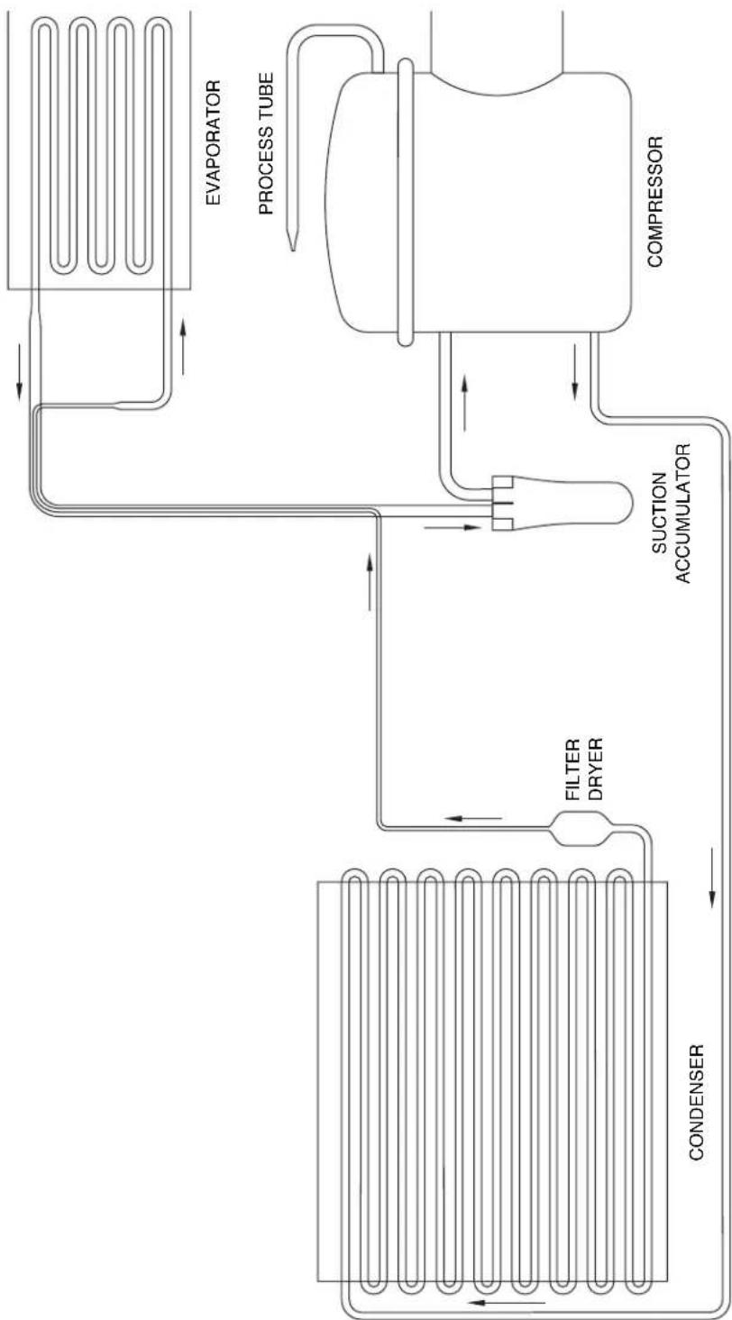
COOLANT SCHEMATIC DIAGRAM
flowchart
graph LR
    A["CONDENSER"] --> B["FILTER DRYER"]
    B --> C["SUCTION ACCUMULATOR"]
    C --> D["COMPRESSOR"]
    D --> E["EVAPORATOR"]
    E --> F["PROCESS TUBE"]
    F --> C
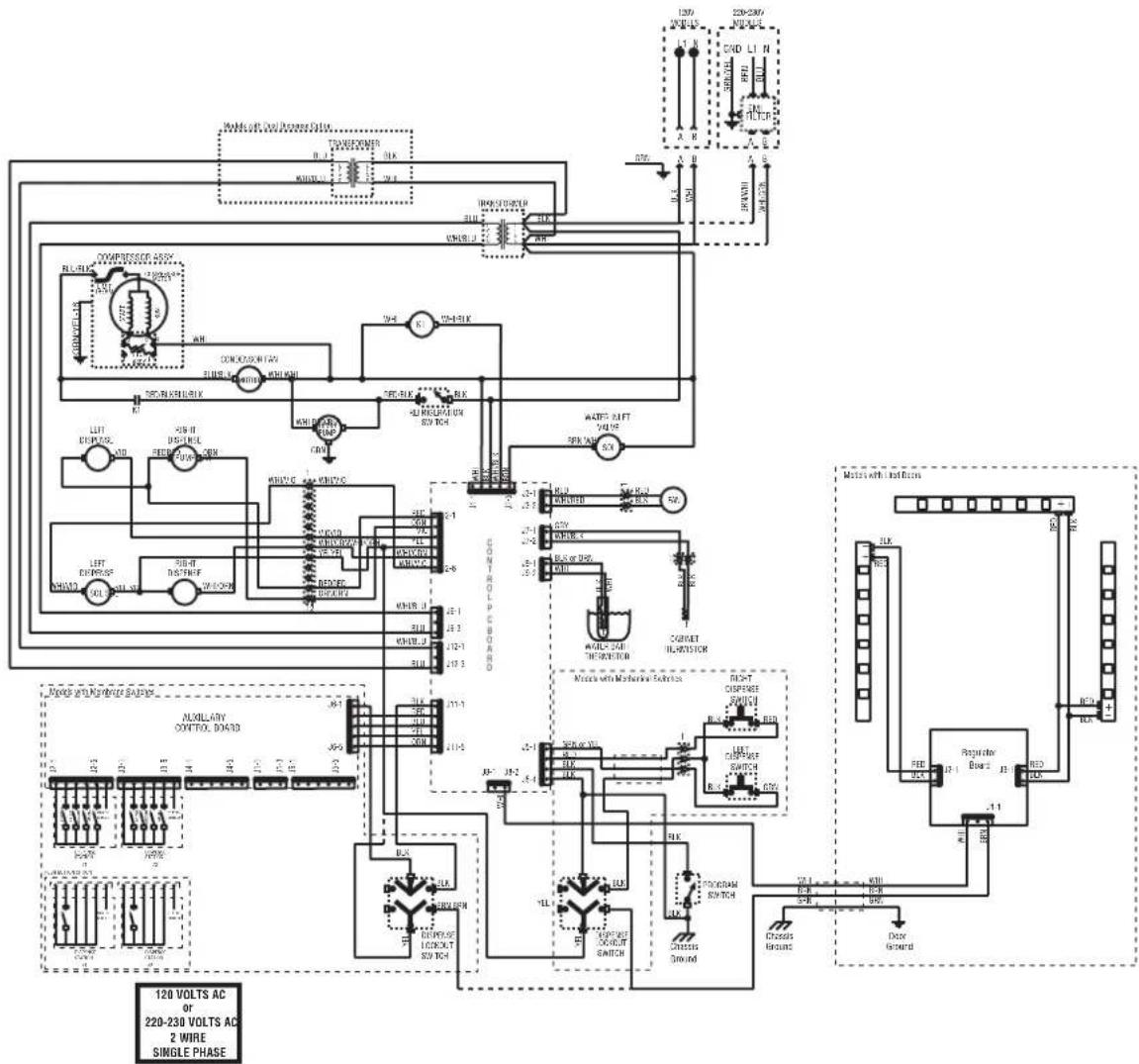
SCHEMATIC WIRING DIAGRAM JDF-2S
(Models with LED Lited Doors)
flowchart
graph TD
    A["120 VOLTs AC"] --> B["220-230 VOLTs AC"]
    B --> C["Single Phase"]
    D["Resistor Board"] --> E["Resistor"]
    E --> F["Control Module"]
    F --> G["Power Supply"]
    H["Motor with Control Schematic"] --> I["Motor with Mechanic Schematic"]
    I --> J["Resistor"]
    J --> K["Resistor"]
    L["Ground"] --> M["Ground"]
    N["Power Supply"] --> O["Power Supply"]
    P["Control Module"] --> Q["Control Module"]
    R["Resistor"] --> S["Resistor"]
    T["Motor with Control Schematic"] --> U["Motor with Mechanic Schematic"]
    U --> V["Resistor"]
    W["Power Supply"] --> X["Power Supply"]
    Y["Control Module"] --> Z["Control Module"]
    AA["Resistor"] --> AB["Resistor"]
    AC["Ground"] --> AD["Ground"]
SCHEMATIC WIRING DIAGRAM JDF-2S
(Models with Flourescent Lited Doors)
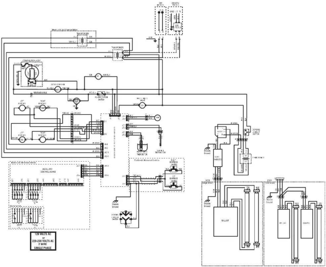
flowchart
graph TD
    A["120 VOLTs AC OF 220-230 VOLTs AC 2 WIRE SINGLE PHASE"] --> B["POWER"]
    B --> C["AC"]
    C --> D["RELAY"]
    D --> E["Switch"]
    E --> F["Motor with Magnetic Switch"]
    F --> G["AC"]
    G --> H["Resistor"]
    H --> I["Ground"]
    I --> J["AC"]
    J --> K["Resistor"]
    K --> L["Switch"]
    L --> M["Motor with Magnetic Switch"]
    M --> N["AC"]
    N --> O["Resistor"]
    O --> P["Switch"]
    P --> Q["Motor with Magnetic Switch"]
    Q --> R["AC"]
    R --> S["Resistor"]
    S --> T["Switch"]
    T --> U["Motor with Magnetic Switch"]
    U --> V["AC"]
    V --> W["Resistor"]
    W --> X["Switch"]
    X --> Y["Motor with Magnetic Switch"]
    Y --> Z["AC"]
    Z --> AA["Resistor"]
    AA --> AB["Switch"]
    AB --> AC["Motor with Magnetic Switch"]
    AC --> AD["AC"]
    AD --> AE["Resistor"]
    AE --> AF["Switch"]
    AF --> AG["Motor with Magnetic Switch"]
    AG --> AH["AC"]
    AH --> AI["Resistor"]
    AI --> AJ["Switch"]
    AJ --> AK["Motor with Magnetic Switch"]
    AK --> AL["AC"]
    AL --> AM["Resistor"]
    AM --> AN["Switch"]
    AN --> AO["Motor with Magnetic Switch"]
    AO --> AP["AC"]
    AP --> AQ["Resistor"]
    AQ --> AR["Switch"]
    AR --> AS["Motor with Magnetic Switch"]
    AS --> AT["AC"]
    AT --> AU["Resistor"]
    AU --> AV["Switch"]
    AV --> AW["Motor with Magnetic Switch"]
    AW --> AX["AC"]
    AX --> AY["Resistor"]
    AY --> AZ["Switch"]
    AZ --> BA["Motor with Magnetic Switch"]
    BA --> BB["AC"]
    BB --> BC["Resistor"]
    BC --> BD["Switch"]
    BD --> BE["Motor with Magnetic Switch"]
    BE --> BF["AC"]
    BF --> BG["Resistor"]
    BG --> BH["Switch"]
SCHEMATIC WIRING DIAGRAM JDF-4S
(Models with LED Lited Doors)
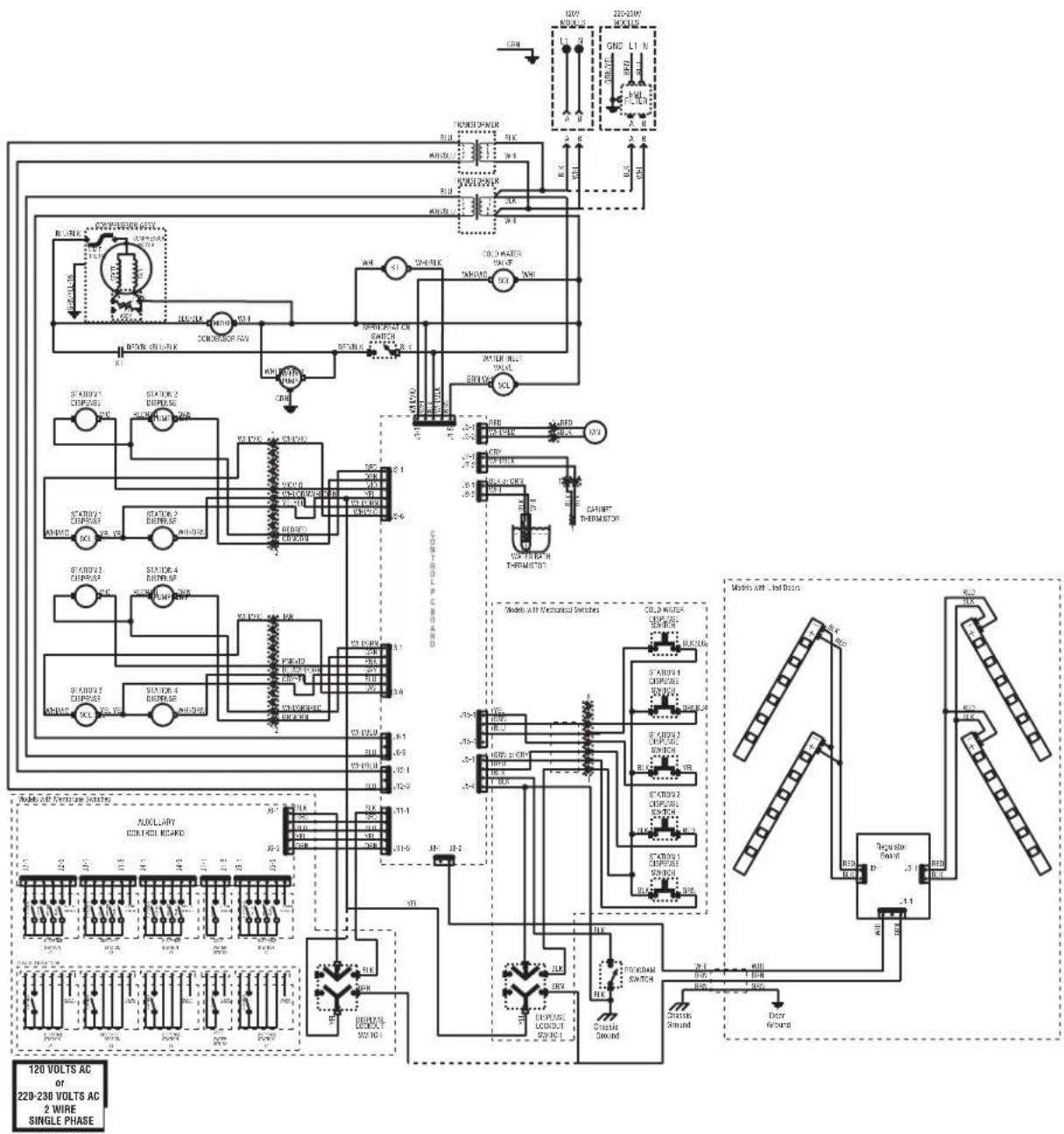
flowchart
graph TD
    A["120 VOLTS AC of 220-230 VOLTS AC 2 WIRE SINGLE PHASE"] --> B["STATION 1 DRINK"]
    A --> C["STATION 2 DRINK"]
    A --> D["STATION 3 DRINK"]
    A --> E["STATION 4 DRINK"]
    A --> F["STATION 5 DRINK"]
    B --> G["RELAYER"]
    C --> H["POWER"]
    D --> I["AC/DC"]
    E --> J["AC/DC"]
    F --> K["AC/DC"]
    G --> L["POWER"]
    H --> M["AC/DC"]
    I --> N["AC/DC"]
    J --> O["AC/DC"]
    K --> P["AC/DC"]
    L --> Q["POWER"]
    M --> R["AC/DC"]
    N --> S["AC/DC"]
    O --> T["POWER"]
    P --> U["AC/DC"]
    Q --> V["POWER"]
    R --> W["AC/DC"]
    S --> X["POWER"]
    T --> Y["AC/DC"]
    U --> Z["POWER"]
    V --> AA["AC/DC"]
    W --> AB["POWER"]
    X --> AC["AC/DC"]
    Y --> AD["POWER"]
    Z --> AE["AC/DC"]
SCHEMATIC WIRING DIAGRAM JDF-4S
(Models with Flourescent Lited Doors)
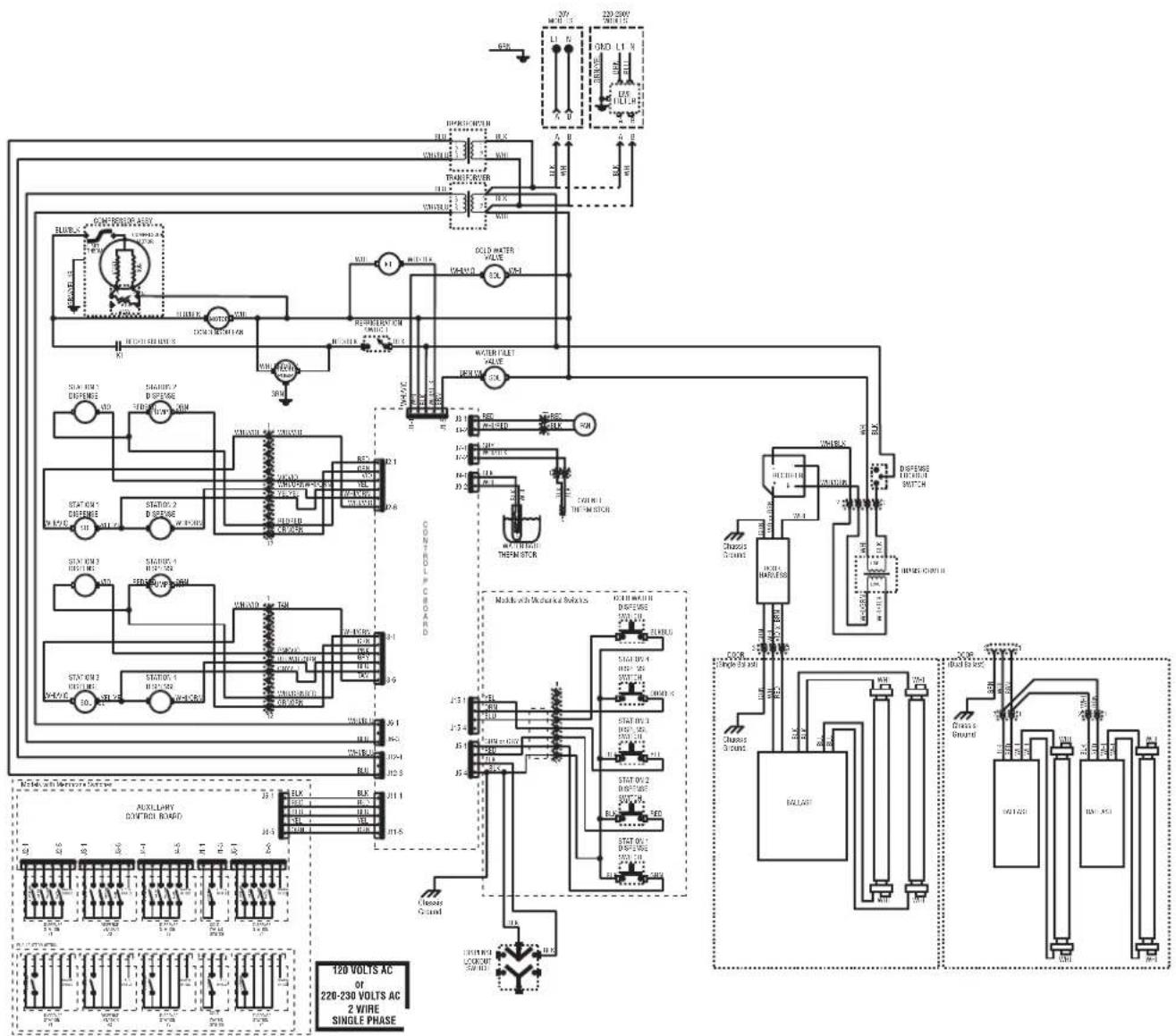
flowchart
graph TD
    A["120 VOLTS AC OF 220-230 VOLTS AC 2 WIRE SINGLE PHASE"] --> B["AUXILIARY SWITCH BOARD"]
    B --> C["STATION 1: BLK, BLK, BLK, BLK, BLK, BLK, BLK, BLK, BLK, BLK, BLK, BLK, BLK, BLK, BLK, BLK, BLK, BLK, BLK, BLK, BLK, BLK, BLK, BLK, BLK, BLK, BLK, BLK, BLK, BLK, BLK, BLK, BLK, BLK, Blu Line"]
    B --> D["STATION 2: BLK, BLK, BLK, BLK, BLK, BLK, BLK, BLK, BLK, BLK, BLK, BLK, BLK, BLK, BLK, BLK, BLK, BLK, BLK, BLK, BLK, BLK, BLK, BLK, BLK, BLK, BLK, BLK, BLk"]
    B --> E["STATION 3: BLK, BLK, BLK, BLK, BLK, BLK, BLK, BLK, BLK, BLK, BLK, BLK, BLK, BLk"]
    B --> F["STATION 4: BLK, BLK, BLk"]
    B --> G["STATION 5: BLk"]
    B --> H["STATION 6: BLk"]
    B --> I["STATION 7: BLk"]
    B --> J["STATION 8: BLk"]
    B --> K["STATION 9: BLk"]
    B --> L["STATION 10: BLk"]
    B --> M["STATION 11: BLk"]
    B --> N["STATION 12: BLk"]
    B --> O["STATION 13: BLk"]
    B --> P["STATION 14: BLk"]
    B --> Q["STATION 15: BLk"]
    B --> R["STATION 16: BLk"]
    B --> S["STATION 17: BLk"]
    B --> T["STATION 18: BLk"]
    B --> U["STATION 19: BLk"]
    B --> V["STATION 20: BLk"]
    B --> W["STATION 21: BLk"]
    B --> X["STATION 22: BLk"]
    B --> Y["STATION 23: BLk"]
    B --> Z["STATION 24: BLk"]
    B --> AA["STATION 25: BLk"]
    B --> AB["STATION 26: BLk"]
    B --> AC["STATION 27: BLk"]
    B --> AD["STATION 28: BLk"]
    B --> AE["STATION 29: BLk"]
    B --> AF["STATION 30: BLk"]
    B --> AG["STATION 31: BLk"]
    B --> AH["STATION 32: BLk"]
    B --> AI["STATION 33: BLk"]
    B --> AJ["STATION 34: BLk"]
    B --> AK["STATION 35: BLk"]
    B --> AL["STATION 36: BLk"]
    B --> AM["STATION 37: BLk"]
    B --> AN["STATION 38: BLk"]
    B --> AO["STATION 39: BLk"]
    B --> AP["STATION 40: BLk"]
    B --> AQ["STATION 41: BLk"]
    B --> AR["STATION 42: BLk"]
    B --> AS["STATION 43: BLk"]
    B --> AT["STATION 44: BLk"]
    B --> AU["STATION 45: BLk"]
    B --> AV["STATION 46: BLk"]
    B --> AW["STATION 47: BLk"]
    B --> AX["STATION 48: BLk"]
    B --> AY["STATION 49: BLk"]
    B --> AZ["STATION 50: BLk"]
    B --> BA["STATION 51: BLk"]
    B --> BB["STATION 52: BLk"]
    B --> BC["STATION 53: BLk"]
    B --> BD["STATION 54: BLk"]
    B --> BE["STATION 55: BLk"]
    B --> BF["STATION 56: BLk"]
    B --> BG["STATION 57: BLk"]
    B --> BH["STATION 58: BLk"]
    B --> BI["STATION 59: BLk"]
    B --> BJ["STATION 60: BLk"]
    B --> BK["STATION 61: BLk"]
    B --> BL["STATION 62: BLk"]
    B --> BM["STATION 63: BLk"]
    B --> BN["STATION 64: BLk"]
    B --> BO["STATION 65: BLk"]
    B --> BP["STATION 66: BLk"]
    B --> BQ["STATION 67: BLk"]
    B --> BR["STATION 68: BLk"]
    B --> BS["STATION 69: BLk"]
    B --> BT["STATION 70: BLk"]
    B --> BU["STATION 71: BLk"]
    B --> BV["STATION 72: BLk"]
    B --> BW["STATION 73: BLk"]
    B --> BX["STATION 74: BLk"]
    B --> BY["STATION 75: BLk"]
    B --> BZ["STATION 76: BLk"]
    B --> CA["STATION 77: BLk"]
    B --> CB["STATION 78: BLk"]
    B --> CC["STATION 79:BL k"]
    B --> CD["STATION 80:BL k"]
QUICK SETUP GUIDE - JDF-2S and JDF-4S (JDF-2S shown)
natural_image
Close-up of hands connecting cables to an electronic device (no visible text or symbols)- Install door cover by first plugging the door harness connector into the machine harness connector located at the bottom of the machine door.
natural_image
Close-up of a hand holding a cylindrical object next to a vertical panel or cabinet (no visible text or symbols)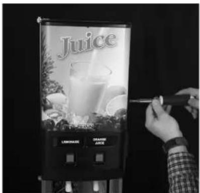
P3578 P3579
- Install door cover. 3. Secure the door cover using 5 screws provided.
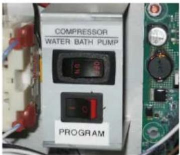
- Place refrigeration switch in the OFF position.
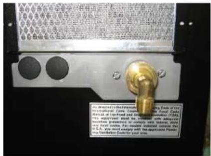
- Connect water supply to machine. (See Plumbing Requirements)
natural_image
Hand inserting a socket into an electrical outlet (no text or symbols visible)- Connect power supply to machine. (See Electrical Requirements)
natural_image
Interior view of an electronic device with visible wiring and tubing (no text or symbols)- Install bath tank fill tube over a nozzle as shown.(See Initial Fill)
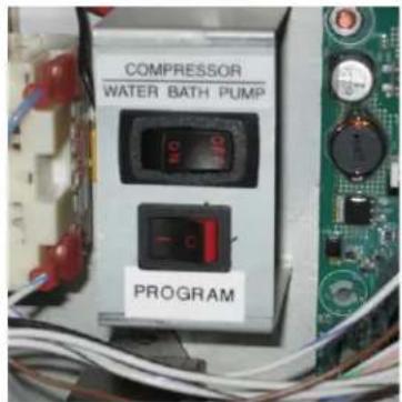
- Place the program switch in the ON position.
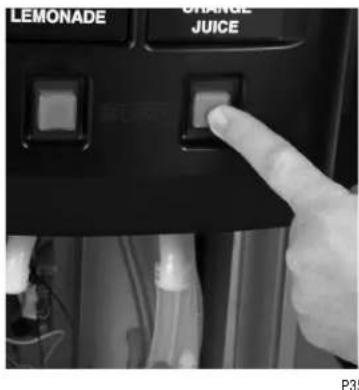
- Hold the dispense switch until water begins to flow into the tank (approx. 10 seconds). When tank is full, water will begin pour out of the overflow tube, Press the dispense button to stop the flow of water.
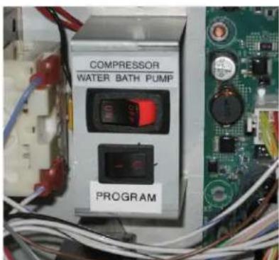
- Place the refrigeration switch in the ON position and the program switch in the OFF position.
natural_image
Interior view of a white plastic appliance inside a refrigerator (no visible text or symbols)-
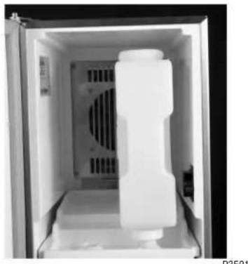
Insert juice containers as shown.
-
Proceed to page 7 in the Operating and Installation manual for calibration instructions and charts.
- BUNN-O-MATIC COMMERCIAL PRODUCT WARRANTY
- CONTENTS
- USER NOTICES
- CHARGE
- CE REQUIREMENTS
- ELECTRICAL REQUIREMENTS
- ELECTRICAL HOOK-UP
- PLUMBING REQUIREMENTS
- DOOR COVER INSTALLATION
- PLUMBING HOOKUP
- INITIAL FILL
- INITIAL FILL (Continued)
- OPERATING CONTROLS
- Refrigeration Switch
- Product Dispense Switch (Mechanical Switch Machines)
- OPERATING CONTROLS (Continued)
- Product Dispense Switch (Membrane Switch Machines)
- Dispense Lockout Switch
- Program Switch
- DISPENSER USE
- Press and Hold Dispensing:
- Portion Control Option (Mechanical Switch Machines)
- Push and Hold Membrane Switch Machines
- Portion Control Option (Membrane Switch Machines)
- CLEANING & PREVENTIVE MAINTENANCE
- Daily: Rinse Procedure
- Daily: Parts Washing
- Sanitize Process for Semi-Automatic and Manual
- For Semi-Automatic Sanitizing Prior to S/N JDF0016500:
- For Semi-Automatic Sanitizing Effective S/N JDF0016500 and up:
- For Manual Sanitizing:
- CLEANING (cont)
- Monthly: Clean Condenser Coils and Filter
- ADJUSTMENT & OPTIONAL SETTINGS
- Water Flow Testing and Adjustment
- Pump Speed Adjustment
- LOADING
- Frozen Concentrates
- Ambient Concentrates (Optional)
- PRIMING
- ADJUSTMENT & OPTIONAL SETTINGS (cont)
- Total Dispense Ratio Set Up Procedure
- Temperature Compensated Refractometer Method
- Optional Cold Water Flow Adjustment
- Dispenser Lockout
- FUNCTION LIST
- FUNCTION LIST (Continued)
- TROUBLESHOOTING
- PROBLEM
- Cold Water Circulation
- PROBABLE CAUSE
- REMEDY
- COOLANT SCHEMATIC DIAGRAM
- SCHEMATIC WIRING DIAGRAM JDF-2S
- SCHEMATIC WIRING DIAGRAM JDF-4S
- (Models with Flourescent Lited Doors)
- QUICK SETUP GUIDE - JDF-2S and JDF-4S (JDF-2S shown)
Brand : Bunn
Model : JDF-2S
Category : Juicer