
ALX135-UD050V - Household Fan Canarm - Free user manual and instructions
Find the device manual for free ALX135-UD050V Canarm in PDF.


| Product Type | Upblast/Downblast Exhaust Fan (Spun Aluminum) |
| Model | ALX135-UD050V |
| Brand | Canarm |
| Wheel Diameter | 13.5 inches |
| Roof Opening | 17.0 inches |
| Dimensions (A x B x C) | 22.25 x 32.13 x 21.00 inches (Upblast Direct Drive) |
| Net Weight | 53 lbs (Upblast Direct Drive) |
| Motor Voltage | 115/208-230 VAC (Single Phase or Three Phase) |
| Motor Type | EC Motor (Electronically Controlled) or Standard AC |
| Speed Control | Variable Speed Control (Single Phase) or VFD (Three Phase) |
| Construction Material | Spun Aluminum |
| Drive Type | Direct Drive or Belt Drive (depending on configuration) |
| Exhaust Configuration | Upblast or Downblast |
| UL Listing | UL/cUL listed for UL762 Restaurant Exhaust (Upblast models) |
| Installation | Roof curb mount; secure with 8 fasteners; caulk and flash |
| Maintenance Interval | At least once a year; every 2-3 months for severe applications |
| Belt Tension | 1/64" deflection per inch of span at ~5 lbs force (belt drive models) |
| Safety Precautions | Lock out power before service; qualified electrician only; not for use with combustible materials |
| Warranty | 1 year from date of purchase (parts only) |
| Spare Parts Availability | See exploded view for part numbers (e.g., Motor Wrap, Wheel, Top Cap) |
Frequently Asked Questions - ALX135-UD050V Canarm
User questions about ALX135-UD050V Canarm
0 question about this device. Answer the ones you know or ask your own.
Ask a new question about this device
Download the instructions for your Household Fan in PDF format for free! Find your manual ALX135-UD050V - Canarm and take your electronic device back in hand. On this page are published all the documents necessary for the use of your device. ALX135-UD050V by Canarm.
USER MANUAL ALX135-UD050V Canarm
READ AND SAVE THESE INSTRUCTIONS

CANARM®
HVAC
The purpose of this manual is to aid in the proper installation and operation of the blowers. These instructions are intended to supplement good general practices and are not intended to cover detailed instruction procedures.
IT IS THE RESPONSIBILITY OF THE PURCHASER TO ASSURE THAT THE INSTALLATION AND MAINTENANCE OF THIS EQUIPMENT IS HANDLED BY QUALIFIED PERSONNEL.
Inspect all shipments carefully for damage. THE RECEIVER MUST NOTE ANY DAMAGE ON THE CARRIER'S BILL OF LADING AND FILE A CLAIM IMMEDIATELY WITH THE FREIGHT COMPANY.
DO NOT LIFT THE UNIT BY THE HOOD OR MOTOR. PLEASE LIFT THE UNIT BY HORIZONTAL SUPPORTS.
GENERAL SAFETY
- All electrical work must be done in accordance with all applicable electrical codes by a qualified electrician.
- Prior to wiring ensure the power supply is locked in the OFF position and that the motor nameplate voltage matches the supply voltage.
- Do not install or operate this fan in an environment where combustible materials, gases or fumes are present.
- Caution: the fan contains rotating parts and electrical service. Appropriate safety precautions should be taken during installation, operation and maintenance. When servicing the fan motor may be hot, allow time for cooling down.
- Before starting the unit, ensure the wheel rotates freely.
- Check and tighten where necessary all nuts, bolts & set screws prior to fan start up (as some may have loosened during shipment).
- Please follow all applicable national, state/provincial and local codes, all of them will supersede this manual.
- Failure to follow the safety instructions in this manual may cause serious injury or death due to electrical shock or high speed rotating parts.
natural_image
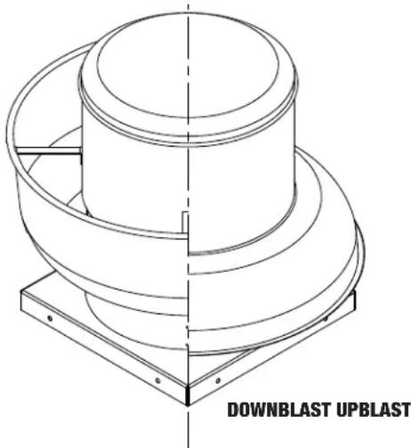
Technical line drawing of a mechanical component with a circular top and flanged base, labeled 'DOWNBLAST UPBLAST' (no other text or symbols)DIMENSION & COMPONENT
UPBLAST MODELS
Upblast Belt Drive Shown
Motor plate detail varies on different sizes


NOTE: DUE TO MOTOR MANUFACTURERS VARIANCES IN DESIGN, PLEASE SEE PAGE 5 FOR MOTOR DIMENSIONAL GUIDELINES.
DOWNBLAST MODELS
Downblast Direct Drive Shown

| Dimensions (inches) | ||||||||||
| Model A B C D E F G ∅ | Wheel Diameter | Roof Opening | Net Weight (lbs) | |||||||
| ALX105-UD | 17.63 | 25.00 | 19.00 | 13.00 | 1.50 | 3.50 | 0.38 | 10.50 | 15.00 | 35 |
| ALX120-UD | 18.63 | 25.00 | 19.00 | 13.00 | 1.50 | 3.50 | 0.38 | 12.25 | 15.00 | 37 |
| ALX135-UD/UB | 22.25 / 25.25 | 32.13 | 21.00 | 17.13 | 1.50 | 3.75 | 0.44 | 13.50 | 17.00 | 53 / 62 |
| ALX150-UD/UB | 23.13 / 26.13 | 32.13 | 21.00 | 17.13 | 1.50 | 3.75 | 0.44 | 15.00 | 17.00 | 58 / 67 |
| ALX165-UD/UB | 27.13 / 31.13 | 37.50 | 24.75 | 21.13 | 2.00 | 4.00 | 0.44 | 16.50 | 20.75 | 100 /108 |
| ALX180-UD/UB | 27.75 / 31.75 | 37.50 | 24.75 | 21.13 | 2.00 | 4.00 | 0.44 | 18.25 | 20.75 | 108 / 116 |
| ALX210-UB | 36.25 | 43.75 | 33.13 | 25.50 | 2.50 | 4.00 | 0.44 | 21.25 | 29.00 | 178 |
| ALX245-UB | 37.00 | 43.75 | 33.13 | 25.50 | 2.50 | 4.00 | 0.44 | 24.50 | 29.00 | 183 |
| Dimensions (inches) | ||||||||||
| Model A B C D E F G ∅ | Wheel Diameter | Roof Opening | Net Weight (lbs) | |||||||
| ALX105-DD | 18.00 | 25.00 | 19.00 | 2.50 | 1.50 | 3.50 | 0.38 | 10.50 | 15.00 | 33 |
| ALX120-DD | 19.00 | 25.00 | 19.00 | 3.50 | 1.50 | 3.50 | 0.38 | 12.25 | 15.00 | 35 |
| ALX135-DD/DB | 22.25 / 25.25 | 31.25 | 21.00 | 3.13 | 2.00 | 3.75 | 0.44 | 13.50 | 17.00 | 51 / 59 |
| ALX150-DD/DB | 23.13 / 26.13 | 31.25 | 21.00 | 3.75 | 2.00 | 3.75 | 0.44 | 15.00 | 17.00 | 56 / 65 |
| ALX165-DD/DB | 27.13 / 31.13 | 36.25 | 24.75 | 5.00 | 2.00 | 4.00 | 0.44 | 16.50 | 20.75 | 100 / 106 |
| ALX180-DD/DB | 27.75 / 31.75 | 36.25 | 24.75 | 5.50 | 2.00 | 4.00 | 0.44 | 18.25 | 20.75 | 104 / 110 |
| ALX210-DB | 36.25 | 43.75 | 33.13 | 5.25 | 2.50 | 4.00 | 0.44 | 21.25 | 29.00 | 176 |
| ALX245-DB | 37.00 | 43.75 | 33.13 | 5.88 | 2.50 | 4.00 | 0.44 | 24.50 | 29.00 | 181 |
Note: Belt drive units are weighted without motor & drives.
INSTALLATION
- Install roof curb, caulk and flash to ensure the water tightness.
- Rotate the blower wheel by hand. Wheel should not be rubbing against the housing inlet. If rubbing occurs, loosen the set screws on the wheel hub and shift the wheel to obtain clearance. Then re-tighten all set screws.
- Complete all subsequent duct connections.
- Secure the fan to the curb cap. Do not lift the unit by the hood or motor. Lift the unit by horizontal supports on direct drive or by motor mounting plate for belt drive unit.
- Use at least 8 proper fasteners to connect the blower base to the roof curb.
- Verify if the power supply is compatible with the equipment.
- Make sure the power line is shut down before wiring the motor to power line.
- Remove top cap, connect power line to the motor/disconnect switch as indicated.
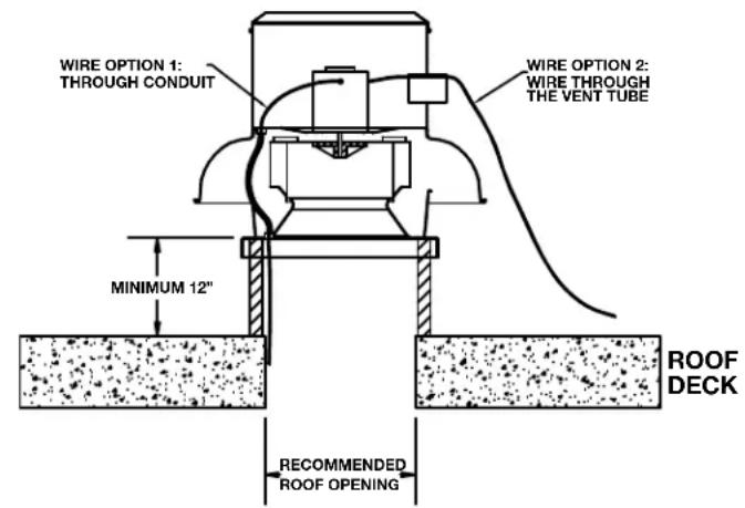
- For all up blast units, the electrical supply enters the motor compartment through the vent tube.
- Ensure all fasteners and set screws are tightened.
- Place the top cap back on the hood.
- Caulk and flash the fan base including the fan base corners and roof curb to ensure good water tightness.
STANDARD WIRING INSTRUCTIONS
- A qualified electrician in accordance with all local and National Electrical Codes should do all wiring.
- Ensure power supply is disconnected and locked out prior to making electrical connections.
- Wire the motor according to the wiring diagram on motor label or on the sticker inside the motor wrap. All motors should be wired to the same rotation as indicated on the sticker on the top plate.
- Leave enough slack in the wiring to allow for motor movement when adjusting the belt tension.
- Excess wire must be restrained in order to prevent it from entering the pulley, shaft or wheel rotating area.
- Disconnect switches are recommended and should be located near the fan in order to, swiftly cut off power in case of an emergency and maintain complete control of the power source.
GENERAL CLEAN AIR APPLICATION (UP BLAST) GENERAL CLEAN AIR APPLICATION, DOWN BLAST

LICATION, DOWN BLAST
Note: ALX105 and ALX120 has only wiring option 1, ALX210 and larger has only wiring option 2 available.
VARIABLE SPEED CONTROL – SINGLE PHASE
Some single phase direct drive motor's running RPM can be adjustable with a variable speed control (please contact factory for more information). The speed control knob starts at off position, then high to low adjust range. At high speed, the speed control would allow the motor running at its maximum RPM. Dial the knob to the low side would let the speed control regulate the voltage on the motor to reduce the RPM.
A minimum speed adjustment is needed to limit the motor RPM range. Follow this procedure to set the minimum speed.
- Motor must be in servicing status to allow the minimum speed setting. Motor would not slow down unless proper load is applied. Motor RPM would be changed under different system (static pressure).
- Turn the main control knob to the lowest speed position.
- Locate and adjust the minimum speed setting, it can be found on the control box itself.
- Motor RPM range would be from full RPM to the RPM just set.
The lowest minimum voltage that may be applied to the motors is 65VAC. Running at lower voltage can cause premature failure to the motor.
VARIABLE FREQUENCY DRIVE – THREE PHASE
For 3 phase motors, a variable frequency drive (VFD) is required to adjust motor speed.
EC (Electronically Controlled) MOTOR SPEED CONTROL
EC motors are equipped with a control module that allows for accurate manual adjustment of motor speed. Motor speed range is from 300 to 1800rpm or maximum rpm for that model.
The control module features a 4 digit LED display that indicates % demand of full speed and motor speed in rpm. The display also indicates an error code message for minor diagnostics if required.
MESSAGE DISPLAYED...
Spd- followed by the instantaneous speed in rpm
dE- followed by S + demand in %
E1- No communications
E2- Under Voltage
Motor speed can be changed by adjusting the speed control pot located on the control module. A small screwdriver can be used to make the speed adjustment.

AC Supply - 115/208-230VAC
Power is connected to the motor and control module through the junction box and wiring harness provided.
Note: For 115VAC operation the blue jumper provided (taped to wire harness) must be inserted into motor power connector. See diagram.
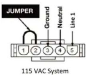

Caution: Operating the motor at 208-230VAC with the jumper will cause significant damage to the motor.

Note: EC motors have a soft start feature. When the power is turned on the control module gathers information from the motor then begins the start up process. After a few seconds the motor will start to turn and reach full set speed in 10-15 seconds.
Remote Speed Control Option (please contact factory for further information)
UL762 RESTAURANT EXHAUST APPLICATION
All up-blast models are UL/cUL listed, they are capable to meet UL762 for Commercial Kitchen application:
- The National Fire Protection Association (NFPA) publication NFPA 96 is the primary source for this application. Also consult local authorities for all other applicable codes and guidelines before installation.
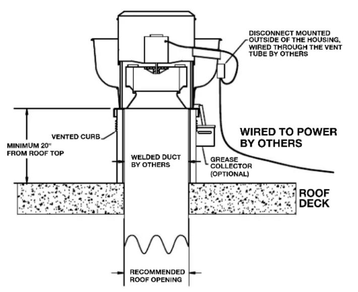
• Exhaust fans used in kitchen ventilation applications must have external wiring. (Wiring must not be installed in the airstream). - Installation must include a means for inspecting, cleaning and servicing the exhaust fan. (Curb hinge, grease collector and outdoor disconnect switches are available for purchase as accessories)
- No dampers can be used in the system.
UP-BLAST UL762 RESTAURANT EXHAUST INSTALLATION UP-BLAST WALL MOUNTED UL762 RESTAURANT EXHAUST INSTALLATION

PRE-START INSPECTION
- Lock out all power sources.
- Inspect all fasteners and set screws and tighten as required.
- Inspect belt alignment and tension where applicable.
- Confirm power source voltage and motor voltage are the same and that the motor is wired correctly.
- Rotate the wheel to ensure that neither the fan blade nor the belts come into contact with the housing.
- Inspect the fan and the ductwork to ensure they are free of debris.
- Check to ensure that all guards and accessories are securely mounted.
START UP
Turn the fan on and inspect for the following:
- Direction of rotation.
- Improper motor amperage.
- Excessive vibration.
- Unusual noise.
- Improper belt tension or alignment (only applicable on belt-drive unit).
If a problem is discovered shut off the fan and refer to the section on troubleshooting to discover the cause of the problem. The fan should be inspected after 30 minutes, 8 hours & 24 hours of operation to ensure all fasteners are tight and belts are properly tensioned and aligned.
MAINTENANCE
Disconnect and secure to the OFF position all electrical power to the fan prior to inspection or servicing. Failure to comply with this safety precaution could result in serious injury or death.
- Ventilator should be checked at least once a year. For critical or severe applications a routine check every two to three months is suggested.
- When moving or installing a belt, don't force the belt over the sheave. Loosen the motor mount so that the belt can be easily slipped over the sheave.
- The belt, on belt driven units, should be removed and carefully checked for cracks, ply separation or irregular wear. A small irregularity in the contact surface of the belt will result in noisy operation. If any of these defects are apparent the belt should be replaced. At the same time check the sheaves for chips, dents or rough surfaces that could damage the belt.
- The correct belt tension is important. Too tight a belt will result in excess bearing pressure, which can cause premature bearing failure and may cause the motor to overload. Too loose a belt will result in slippage, which will burn out belts. Proper belt deflection should be 1/64" (half way between sheave centers) for each inch of belt span when a force of approximately 5 lbs. is applied.
- The belt alignment should be checked to be sure that the belt is running perpendicular to the rotating shafts. Motor and drive shafts must be parallel.
- A periodic inspection of all fasteners should be carried out to ensure they have not loosened due to vibration. Particular attention should be paid to fasteners attaching the wheel to the shaft and those attaching the shaft to the bearing.
FAN TROUBLESHOOTING

WARNING
MAKE SURE THE UNIT IS NOT CAPABLE OF OPERATION DURING REPARATION.
| PROBLEM POSSIBLE ISSUE SOLUTION | ||
| Excessive noise/vibration | Wheel rubbing inlet | Adjust wheel, loosen set screw(s) and move the wheel, acquiring clearance between inlet and wheel, then re-tighten set screw(s) |
| Wheel unbalance Check wheels for debris or dirt build up and clean when necessary | ||
| Object in rotation area or housing Remove object | ||
| Motor compartment loose Re-tighten the fasteners | ||
| Fan does not operate | Malfunction of electrical supply Check supply voltage, fuse and switch | |
| Malfunction of motor Check wiring and overload protector | ||
| Motor overload/overheat Wrong | wheel rotation Re-wire the motor to change direction of rotation | |
| Reduced airflow | Damper Malfunction | Check opening side of back draft damper, check operation status of controlled damper |
| Wrong wheel rotation Re-wire the motor to change direction of rotation | ||
| Improper Duct System Check obstruction of duct in the duct or dirty filter | ||
FAN MOTOR DIMENSIONAL GUIDELINES

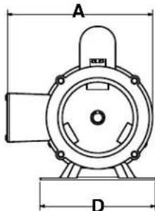
| FAN FRAME SIZES MAX "A" | MAX "B" | MAX "C" | MAX "D" | RESILIENT BASE | MAX SHEAVE DIA. | ||
| ALX135UB/DB | 48, 56 | 8.5 | 6.5 | 10.5 | 7 | NO | 5.5 |
| ALX150UB/DB | 48, 56 | 8.5 | 6.5 | 10.5 | 7 | NO | 5.5 |
| ALX165UB/DB | 48, 56, 143, 145 | 8.5 | 8 | 13 | 7 | NO | 5.5 |
| ALX180UB/DB | 48, 56, 143, 145 | 8.5 | 8 | 13 | 7 | NO | 5.5 |
| ALX210UB/DB | 56, 143, 145, 182, 184 | 11.5 | 11 | 12 | 8 | YES | 8 |
| ALX245UB/DB | 56, 143, 145, 182, 184 | 11.5 | 11 | 12 | 8 | YES | 8 |
| FAN | MAX "A" | MAX "B" | MAX "C" | C-FACE ONLY |
| ALX105/120UD | 14 | 14 | 8.5 | 56 FRAME |
| ALX105/120DD | 10 | 10 | 7.5 | 56 FRAME |
| ALX135/150UD | 15 | 15 | 15 | 56 FRAME |
| ALX135/150DD | 15 | 15 | 15 | 56 FRAME |
| ALX165UD | 16 | 16 | 15.5 | 56 FRAME |
| ALX165DD | 16 | 16 | 15.5 | 56 FRAME |
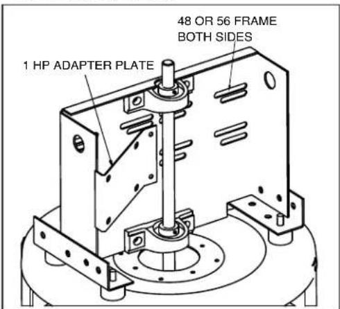
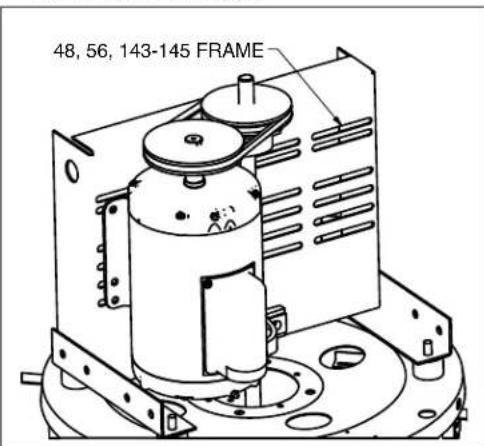
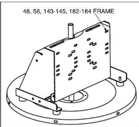
MOTOR MOUNTING
ALX135/ALX150
ALX165/ALX180
ALX210/ALX245
ALX SERIES SPUN ALUMINUM UPBLAST EXHAUSTERS - EXPLODED VIEW
| ITEM # | DESCRIPTION | QTY |
| 1 | T OP CAP 1 | |
| 2MOTOR | WRAP 1 | |
| 3 | MOTOR SUPPORT PLATE | 1 |
| 4 | VIBRATION ELIMINATOR | 4 |
| 5TOP PLATE 1 | ||
| 6 | UPBLAST APRON | 1 |
| 7VENT 1 | ||
| 8 | VERTICAL BRACKET | 4 |
| 9INLET BA | AFFLE 4 | |
| 10 | DRAIN | 4 |
| 11 | MOTOR SUPPORT RAIL | 2 |
| 12 | HORIZONTAL BRACKET | 4 |
| 13 | BASE1 | |
| 14 | BLOWER WHEEL | 1 |

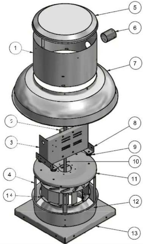
ALX SERIES SPUN ALUMINUM DOWNBLAST EXHAUSTERS - EXPLODED VIEW
| ITEM # | DESCRIPTION | QTY |
| 1 | MOTOR WRAP | 1 |
| 2 | BEARING | 2 |
| 3 | MOTOR SUPPORT PLATE | 1 |
| 4 | VERTICAL BRACKET | 4 |
| 5 | TOP CAP | 1 |
| 6 | VENT TUBE | 1 |
| 7 | DOWNBLAST APRON | 1 |
| 8 | MOTOR SUPPORT RAIL | 2 |
| 9 | VIBRATION ELIMINATOR | 4 |
| 10 | SHAFT | 1 |
| 11 | TOP PLATE | 1 |
| 12 | INLET BAFFLE | 1 |
| 13 | BASE1 | |
| 14 | BLOWER WHEEL | 1 |
NOTE: General models are shown above. Actual unit might vary according to size.
WARRANTY
CANARM Ltd. warrants every new fan to be free of defects in material and workmanship to the extent that, within a period of one year from the date of purchase CANARM Ltd. shall either repair or replace at CANARM's option, any unit or part thereof, returned freight prepaid, and found to be defective.
This warranty does not include any labour or transportation costs incidental to the removal and reinstallation of the unit at the user's premises.
Components repaired or replaced are warranted through the remainder of the original warranty period only; it is null and void in case of alteration, accident, abuse, neglect, and operation not in accordance with instructions.
NOTICE: No warranty claims will be honored by CANARM Ltd. unless prior authorization is obtained.
- CANARM®
- HVAC
- GENERAL SAFETY
- DIMENSION & COMPONENT
- UPBLAST MODELS
- DOWNBLAST MODELS
- INSTALLATION
- STANDARD WIRING INSTRUCTIONS
- VARIABLE SPEED CONTROL – SINGLE PHASE
- VARIABLE FREQUENCY DRIVE – THREE PHASE
- EC (Electronically Controlled) MOTOR SPEED CONTROL
- MESSAGE DISPLAYED...
- AC Supply - 115/208-230VAC
- UL762 RESTAURANT EXHAUST APPLICATION
- PRE-START INSPECTION
- START UP
- MAINTENANCE
- FAN TROUBLESHOOTING
- WARNING
- FAN MOTOR DIMENSIONAL GUIDELINES
- MOTOR MOUNTING
- ALX SERIES SPUN ALUMINUM UPBLAST EXHAUSTERS - EXPLODED VIEW
- ALX SERIES SPUN ALUMINUM DOWNBLAST EXHAUSTERS - EXPLODED VIEW
- WARRANTY
Brand : Canarm
Model : ALX135-UD050V
Category : Household Fan