WVU-26 - Range hood Wells - Free user manual and instructions
Find the device manual for free WVU-26 Wells in PDF.


| Product Type | Ventless Universal Modular Hood System |
| Model | WVU-26 |
| Brand | Wells |
| Intended Use | For light and medium duty electric cooking appliances only |
| Power Supply | 208/240V, 50/60 Hz, single phase |
| Amperage (Hood Only) | 6 A |
| Wattage (Hood Only) | 1.4 kW |
| Circuit Requirement | 15 A dedicated circuit for hood; cooking appliances sized separately |
| Under-Hood Appliance Max Output | 22 kW |
| Under-Hood Appliance Max Width | 24 inches (610 mm) |
| Under-Hood Appliance Max Depth from Back Wall | 25.5 inches (648 mm) |
| Cooking Surface Height | 34" - 38" (864-965 mm) from floor |
| Minimum Ceiling Height | 96 inches (floor to overhead) |
| Combustible Object Clearance (top) | 99" or more, or 3" above unit with door open |
| Filtration System | HEPA / Charcoal filter pack plus grease baffle and grease cup |
| Filter Service Life | Replace when indicator light illuminates; cannot be cleaned |
| Fire Suppression System | Integrated Ansul® system with Ansulex® Low pH agent, fusible links (165°F and 212°F), manual pull station |
| Safety Interlocks | Disables cooking appliances if filters missing, airflow insufficient, or fire system activated |
| Control Panel Indicators | Power ON, Check Filters, Replace Filter, Service Required |
| Cleaning Frequency | Weekly: grease baffle and cup; Monthly: interior wiping |
| Warranty (Hood Parts/Labor) | 2 years parts, 1 year labor |
| Certifications | ETL listed, UL 710B, NSF Standard 4 |
| Construction | Made in USA, adjustable legs, stainless steel exterior |
Frequently Asked Questions - WVU-26 Wells
User questions about WVU-26 Wells
0 question about this device. Answer the ones you know or ask your own.
Ask a new question about this device
Download the instructions for your Range hood in PDF format for free! Find your manual WVU-26 - Wells and take your electronic device back in hand. On this page are published all the documents necessary for the use of your device. WVU-26 by Wells.
USER MANUAL WVU-26 Wells
265 Hobson Street, Smithville, Tennessee 37166
telephone: 314-678-6314
fax: 314-781-2714
www.wells-mfg.com
natural_image
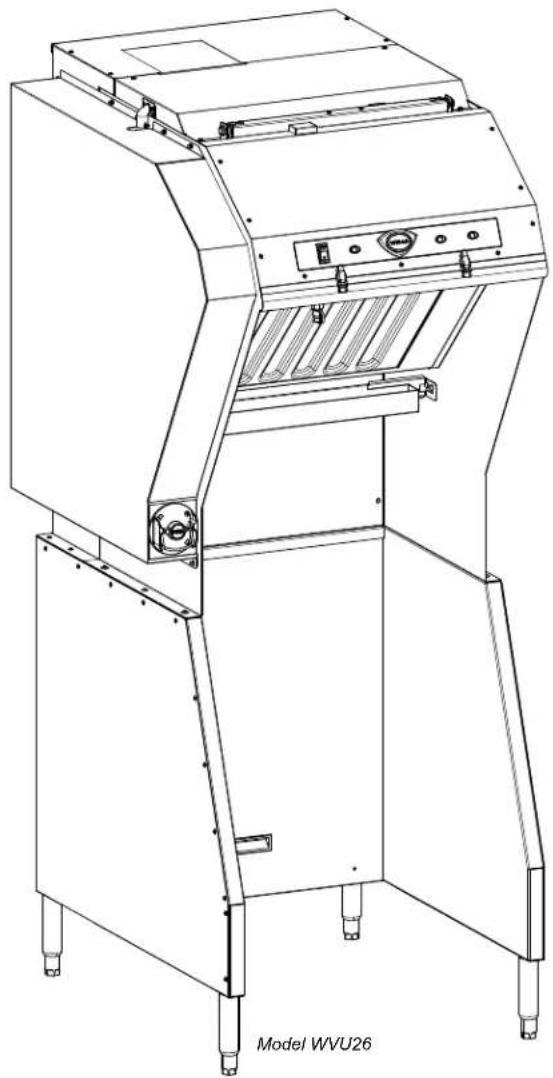
Line drawing of a Model WVU26 industrial machine with open door and control panel (no text or symbols on the device itself)OWNER'S MANUAL
VENTLESS UNIVERSAL
MODULAR HOOD SYSTEM
for
ELECTRIC
COOKING
APPLIANCES
MODEL
WVU-26
Manual Includes
INSTALLATION
USE & CARE
EXPLODED VIEW
PARTS LIST
WIRING DIAGRAM

natural_image
Silhouette of a person reading a book (no text or symbols visible)IMPORTANT: DO NOT DISCARD THIS MANUAL
This manual is considered to be part of the appliance and is to be given to the OWNER or MANAGER of the restaurant, or to the person responsible for TRAINING OPERATORS of this appliance. Additional manuals are available from your WELLS DEALER.
THIS MANUAL MUST BE READ AND UNDERSTOOD BY ALL PERSONS USING OR INSTALLING THIS APPLIANCE. Contact your WELLS DEALER if you have any questions concerning installation, operation or maintenance of this equipment.
LIMITED EQUIPMENT WARRANTY
Wells Manufacturing warranties new products to be free from defects in material and/or workmanship for a period of one [1] year from the date of original installation, except as noted below. Defects that occur as a result of normal use, within the time period and limitations defined in this warranty, will at Wells' discretion have the parts replaced or repaired by Wells or a Wells-authorized service agency.
THIS WARRANTY IS SUBJECT TO ALL LISTED CONDITIONS.
Repairs performed under this warranty are to be performed by a Wells-authorized service agency. Wells will not be responsible for charges incurred or service performed by non-authorized repair agencies. In all cases, the nearest Wells-authorized service agency must be used.
Wells will be responsible for normal labor charges incurred in the repair or replacement of a warranted product within 50 miles (80.5 km) of an authorized service agency. Time and expense charges for anything beyond that distance will be the responsibility of the owner. All labor will need to be performed during regular service hours. Any overtime premium will be charged to the owner. For all shipments outside the U.S.A. and Canada, please see the International Warranty for specific details.
It is the responsibility of the owner to inspect and report any shipping damage claims, hidden or otherwise, promptly following delivery.
No mileage or travel charges will be honored on any equipment that is deemed portable. In general, equipment with a cord and plug weighing less than 50 lb. (22.7 kg) is considered portable and should be taken or shipped to the closest authorized service agency, transportation prepaid
CONTACT
Should you require any assistance regarding the operation or maintenance of any Wells equipment; write, phone, fax or email our service department. In all correspondence mention the model number and the serial number of your unit, as well as the voltage or type of gas you are using.
Business hours are 8:00 a.m. to 4:30 p.m. Central Standard Time Telephone 314.678.6314
Fax 314.781.2714
Email customerservice@star-mfg.com
www.wells-mfg.com
WARRANTY EXCLUSIONS
THE FOLLOWING WILL NOT BE COVERED UNDER WARRANTY.
- Any product which has not been installed, cleaned, maintained, or used in accordance with the directions published in the appropriate installation sheet and/or owner's manual as well as national and local codes, including incorrect gas or electrical connection. Wells is not liable for any unit which has been mishandled, abused, misapplied, subjected to chlorides, harsh chemicals, or caustic cleaners, damaged from exposure to hard water, modified by unauthorized personnel, damaged by flood, fire, or other acts of nature [or God], or which have an altered or missing serial number.
- Installation, labor, and job checkouts, calibration of heat controls, air and gas burner/bypass/pilot adjustments, gas or electrical system checks, voltage and phase conversions, cleaning of equipment, or seasoning of griddle surface.
- Replacement of fuses or resetting of circuit breakers, safety controls, or reset buttons.
- Replacement of broken or damaged glass components, quartz heating elements, and light bulbs.
- Labor charges for all removable parts in gas charbroilers and hotplates, including but not limited to burners, grates, and radiants.
- Any labor charges incurred by delays, waiting time, or operating restrictions that hinder a service technician's ability to perform service.
- Parts that fail or are damaged due to normal wear or labor for replacement of Items that can easily be replaced during a daily cleaning routine. such as but not limited to silicone belts, PTFE non-stick sheets, knobs, control labels, bulbs, fuses, quartz heating elements, baskets, racks, and grease drawers.
- Components that should be replaced when damaged or worn, but have been field-repaired instead [eg. field-welded fry pots].
- Any loss of business or profits.
ADDITIONAL WARRANTIES
Specialty/chain specific versions may also have additional and/or extended warranties.
| PRODUCTS PARTS LABOR | ||
| universal ventless hoods 2 years | 1 year | |
| canopy hoods 2 years 1 year | ||
| "Cook'n Hold" equipment [HW10, HWSMP, LLSC7, LLSC7WA, LLSC11, and LLSC11WA] | 2 years 1 year | |
| cast iron grates, burners, and burner shields | 1 year | |
| original Wells parts sold to repair Wells equipment | 90 days | |
| Service First 1 year |
TABLE OF CONTENTS
WARRANTY
SPECIFICATIONS 1
WARNINGS - ENGLISH 2
WARNINGS - FRENCH 3
FEATURES & OPERATING CONTROLS 4
PRECAUTIONS & GENERAL INFORMATION 5
AGENCY LISTING INFORMATION 6
INSTALLATION 6
ANSUL® INSTALLATION & SETUP 9
OPERATION 11
CLEANING INSTRUCTIONS 12
TROUBLESHOOTING SUGGESTIONS 15
REQUIRED MAINTENANCE & MAINTENANCE LOGS 15
MSDS Ansulex Low-pH ^TM 18
WIRING DIAGRAM 20
EXPLODED VIEW & PARTS LIST 21
INTRODUCTION
Thank You for purchasing this Wells Manufacturing appliance.
Proper installation, professional operation and consistent maintenance of this appliance will ensure that it gives you the very best performance and a long, economical service life.
This manual contains information and instructions for the ventless ventilation hood, its use and care.
For information regarding cooking appliance(s), please refer to the manufacturer's operation manual.
ELECTRICAL SPECIFICATIONS
| MODEL | VOLTS | AMPS 1ø | WATTS | POWER SUPPLY |
| 50/60Hz 1 ø | ||||
| WVU26 | 208/240V | 6A | 1.4kW | Each cooking appliance requires a circuit sized to the appliance power requirements, connected to an interlock contactor with 208/240 volt control coil rating. |
UNDER-HOOD APPLIANCE LIMITATIONS:
- Appliance Maximum output of 22Kw
- Cooking surface must be 34-38" (864—965mm) from floor, no more than 25.5" (648mm) from back wall, no wider than 24" (610mm)
- Appliance must be installed per manufactures instructions.
- Electrical appliance only. Not Intended for gas fired units.
WARNINGS - ENGLISH
IMPORTANT: DO NOT DISCARD THIS MANUAL
This manual is considered to be part of the appliance and is to be given to the OWNER or MANAGER of the restaurant, or to the person responsible for TRAINING OPERATORS of this appliance. Additional manuals are available from your WELLS DEALER.
THIS MANUAL MUST BE READ AND UNDERSTOOD BY ALL PERSONS USING OR INSTALLING THIS APPLIANCE. Contact your WELLS DEALER if you have any questions concerning installation, operation or maintenance of this equipment.

DANGER FIRE HAZARD
Fire suppression system must be charged and certified by an authorized Ansul® distributor.
DO NOT attempt to modify or bypass the fire suppression system.
An uncontrolled fire can cause serious injury or death.
WARNING:
If the fire suppression system is discharged, a buzzer will sound continuously. The unit will remain inoperable until the fire suppression system is serviced, recharged and reset by an authorized Ansul® distributor.
NOTE:
If a REMOTE MANUAL PULL STATION is installed, moving the ventilator for any reason may cause the Ansul® system to discharge.
DANGER - DO NOT BLOCK ACCESS TO THE FIRE EXTINGUSHING MANUAL PULL.

DANGER: SUFFOCATION HAZARD
"Do not attempt to use this ventilator with gas-fired units. This ventilator will not remove products of combustion. Unvented exhaust gasses can be deadly."

WARNING: SHOCK HAZARD
All servicing requiring access to non-insulated electrical components must be performed by a factory authorized technician.
DO NOT open any access panel which requires the use of tools. Failure to follow this warning can result in severe electrical shock.

WARNING: RISK OF INJURY
Installation procedures must be performed by a qualified technician with full knowledge of all applicable electrical codes. Failure can result in personal injury and property damage.
WARNING:
SLIP AND FALL HAZARD
DO NOT operate any grease-producing cooking appliance unless the grease cup is properly installed. Oil will drip onto floor creating a slipping hazard.
WARNING:
DO NOT attempt to wash the HEPA / CHARCOAL filter pack or pre-filter. Water absorption will render the filter unusable. Use of a wet or clogged filter will cause the ventilator system to shut down. Use only new, clean Wells® Authorized Service Parts. Keep spare filter packs on hand to avoid distrupions. Service Department 1-314-678-6314. Exposed surfaces can be hot to the touch and may cause burns. Allow unit to cool before cleaning or servicing.
WARNINGS - FRENCH
IMPORTANT : NE JETEZ PAS CE MANUEL
Universal Ventless Hood Features & Operating Controls
PRECAUTIONS AND GENERAL INFORMATION
This ventilator hood is part of an engineered system and is intended for use in commercial establishments only.
This ventilator is intended for commercial establishments for use in the preparation food for human consumption. No other use is recommended or authorized by the manufacturer or its agents.
Operators of this appliance must be familiar with the appliance use, limitations and associated restrictions. Operating instructions must be read and understood by all persons using or installing this appliance.
This ventilator hood system is designed to reduce odor emissions, but will not completely eliminate all cooking odors. Air exchange rates at the installation site must comply with the requirements of the local jurisdictional authority. To ensure that odors do not accumulate, recommended minimum air exchange is 400 cfm into and out of the site.
This unit is intended for use with light and medium duty electric cooking appliances only. Cooking appliances placed under this ventilator must comply with the restrictions set forth in the Installation Instructions shipped with the unit.
Also see Under Hood Cooking Appliance Limitations, page 1.
Do not connect or energize this appliance until all installation instructions are read and followed. Damage to the ventilator and/or cooking appliances may result if these instructions are not followed. Disconnect this appliance from electrical power before performing any maintenance or servicing.
Cleanliness of this appliance is essential to good sanitation. Read and follow all included cleaning instructions and schedules to ensure the safety of the food product.
This appliance is not jet stream approved. Do not direct water jet or steam jet at this appliance, or at any control panel or wiring. Do not splash or pour water on, in or over any controls, control panel or wiring. Do not attempt to wash filter packs. Water will cause their immediate failure and disable the ventilator.
Exposed surfaces of this appliance can be hot to the touch and may cause burns.
Avoid storing flammable or combustible materials in, on or near the ventilator or associated cooking appliance.
The technical content of this manual, including any wiring diagrams, schematics, parts breakdown illustrations and/or adjustment procedures, is intended for use by qualified technical personnel.
Any procedure which requires the use of tools must be performed by a qualified technician.
All supplied instructions, diagrams, schematics, parts breakdown illustrations, notices and labels must remain with the appliance if it is sold or moved to another location.
This appliance is made in the USA. Unless otherwise noted, this appliance has American sizes on all hardware.

DANGER: SUFFOCATION HAZARD
Do not attempt to use this ventilator with gas-fired units. This ventilator will not remove products of combustion. Unvented exhaust gasses can be deadly.

WARNING: SHOCK HAZARD
All servicing requiring access to non-insulated electrical components must be performed by a factory authorized technician.
DO NOT open any access panel which requires the use of tools. Failure to follow this warning can result in severe electrical shock.
IMPORTANT:
The ventilator is disabled when the filters are plugged to the point of insufficient airflow for proper operation. Also, power to the cooking appliances is interrupted if either the filter pack or the grease baffle is removed.
It is the responsibility of the store management to maintain sufficient spares of filter packs to avoid prolonged shutdown of the ventilator when this filter pack is expended. Filter packs cannot be cleaned.
Wells Manufacturing assumes no liability for loss of business due to filter related shutdown.
AGENCY LISTING INFORMATION

Intertek
UL710B
Recirculating System

Intertek
NSF
STD 4
This appliance conforms to NSF Standard 4 for sanitation only if installed in accordance with the supplied Installation Instructions and operated and maintained in accordance with the instructions in this manual.
This appliance is ETL listed.
INSTALLATION
NOTE: DO NOT discard the carton or other packing materials until you have inspected the appliance for hidden damage and tested it for proper operation. Refer to SHIPPING DAMAGE CLAIM PROCEDURE on the inside front cover of this manual.

WARNING: RISK OF INJURY
Installation procedures must be performed by a qualified technician with full knowledge of all applicable electrical codes. Failure can result in personal injury and property damage.
IMPORTANT:
Fire suppression system must be charged and certified by an authorized Ansul® distributor. Ventilator will not operate and cooking appliance will not be energized until the Ansul® fire suppression system has been charged.
IMPORTANT:
After cooking appliances are positioned under the hood, swivel nozzles must be positioned per Ansul® recommendations.
UNPACKING & INSPECTION
Carefully remove the appliance from the carton. Remove all protective plastic film, packing materials and accessories from the appliance before connecting electrical power or otherwise performing any installation procedure.
Carefully read all instructions in this manual before starting any installation.
Read and understand all labels and diagrams attached to the ventilator.
Carefully account for all components and accessories before discarding packing materials.
COMPONENTS
Per module:
4 ea. Leg Assemblies
1 ea. Grease baffle
1 ea. Filter pack
1 ea Grease cup
Ansul® components - must be installed by an authorized ANSUL® distributor only:
1 ea. Fire suppression agent tank
1 ea. Fire suppression agent (Ansulex® Low pH) 1.5 gal.
1 ea. Fire suppression system charging cartridge
Store these components in a convenient place for later use.
INSTALLATION (continued)
SERVICE TECHNICIAN INSTALLATION NOTES
This ventilator hood is to be used with light-duty and medium-duty electrically powered cooking appliances only.
- DO NOT attempt to use this ventilator hood with gas-fired units.
- DO NOT use this ventilator hood with electrical appliances whose dimensions or wattage characteristics exceed those defined in the Under Hood Cooking Appliance Limitations, page 1.
Installation and start up must be performed by an Authorized Installation Company.
Ansul® Installer must complete the WARRANTY INITIATION form (2M-303912) included with the unit for the warranty to begin, and record installation particulars on the CUSTOMER SERVICE DATA form located at the end of this manual.
IT IS THE RESPONSIBILITY OF THE INSTALLER TO verify that this VENTILATOR installation is in compliance with the specifications listed in this manual, with local code requirements, and in accordance with the STANDARD FOR VENTILATON CONTROL AND FIRE PROTECTION OF COMMERCIAL COOKING OPERATIONS as detailed in N.F.P.A 96 (current edition).
NOTE: Certain codes require FRYERS to be restrained with a TETHER or other RESTRAINT DEVICE. If this ventilator is to be used with a fryer, it is the RESPONSIBILITY OF THE INSTALLER to check with the AUTHORITY HAVING JURISDICTION, in order to ascertain the applicability of this requirement to this specific installation. Any restraint device must allow access to the back and sides of the unit to provide for servicing and maintenance, and must not interfere with the operation of the fire suppression system.
SETUP
Setup the appliance only on a firm, level, non-combustible surface. Verify local codes for requirements. Concrete, tile, terrazzo or metal surfaces are recommended. Metal over combustible material may not meet code for non-combustible surfaces.
Verify vertical clearances. Unit requires a minimum of 96" (floor to overhead) to allow for adequate air circulation and replacement of filters. Combustible object from the top must be 99" or higher, or 3" above the unit while the control panel door is open.
Verify that the unit sits firmly on all legs or casters depending on your model. With a spirit level, check that the appliance is level front-to-back and side-to-side. With the adjustable legs, adjust as required to level the appliance. In order to prevent tipping or deflection, legs must be adjusted such that all legs are in firm contact with the floor.

DANGER:
SUFFOCATION HAZARD
Do not attempt to use this ventilator with gas-fired units. This ventilator will not remove products of combustion. Unvented exhaust gasses can be deadly.

WARNING: SHOCK HAZARD
All servicing requiring access to non-insulated electrical components must be performed by a factory authorized technician. DO NOT open any access panel which requires the use of tools. Failure to follow this warning can result in severe electrical shock.

CAUTION: RISK OF DAMAGE
DO NOT connect or energize this appliance until all installation instructions are read and followed. Damage to the appliance will result if these instructions are not followed.
IMPORTANT:
If a remote pull station is to be used, ventilator cannot be moved without first disabling the remote pull station.
Contact your Ansul® agent for details.
INSTALLATION (continued)

DANGER:
SUFFOCATION HAZARD
Do not attempt to use this ventilator with gas-fired units. This ventilator will not remove products of combustion. Unvented exhaust gasses can be deadly.

WARNING SHOCK HAZARD
Electrical connections must be made by a licensed electrician.

CAUTION: FIRE HAZARD HEALTH HAZARD
The cooking appliance must be connected to the cooking appliance contactor, the control circuit of which is controlled by the ventilator.
Failure to control cooking appliances will provide no protection in the event of a fire, nor will cooking vapors and odors be contained in the event of ventilator hood malfunction.
CAUTION: SHOCK HAZARD
The ground lug of this appliance must be connected to a suitable building ground.
IMPORTANT:
Contact a licensed electrician to install and connect electrical power to the appliance.
IMPORTANT:
Damage due to being connected to the wrong voltage or phase is NOT covered by warranty.
ELECTRICAL INSTALLATION
The ventless hood system is rated 208/240 volt single phase and requires a 15 amp electrical circuit for hood operation. A 208/240 volt 3 pole contactor is provided for electrical supply and appliance interface connection. The ground lug adjacent to the supply connection contactor must be connected to a suitable building ground. All under hood appliances must be controlled by the appliance interface. This interface will disable all under hood appliances in the event the hood is switched off, the required filters are not in place, the airflow is less than the required minimum or the fire suppression system is activated. The supply connection and appliance interface contactor is located in the electrical box below the Ansul fire suppression mechanical actuator. Access is provided through the front lift off door. This electrical box also houses a dry contact relay for connection to a building fire alarm system. Both Normally Open and Normally Closed contacts are provided. The installation and all connections shall be in accordance with the National Electric Code NFPA 70. It is the responsibility of the electrical contractor to provide suitable wiring, flexible or rigid conduit, and an appropriate strain relief. Overcurrent protection must be provided for all circuits.
SUPPLY CONNECTIONS
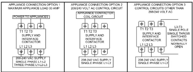
Under hood appliances with a load of less than 30 amps can be controlled directly by the supply connection contactor. Single phase supply connections are made to contactor terminals L1 and L2. Three phase supply connections are made to contactor terminals L1, L2 and L3. Appliance load connections are made to contactor terminals T1, T2 and T3. See equipment interface option 1.
Appliances rated more than 30 amps must be controlled by a customer supplied contactor. This contactor must be a UL listed, definite purpose AC resistive air heating type, suitable for the appliance load. Single phase connection to the hood is made to supply connection contactor terminals L1 and L2. Customer supplied contactor control circuits rated 208 or 240 volt AC can be connected to contactor terminals T1 and T2. See equipment interface option 2.
Customer supplied contactors with control circuits rated other than 208 or 240 volt AC can be controlled through single pole single throw switched contactor terminals L3 and T3. See equipment interface option 3.
The ventilator will operate properly, and the control relay will be energized, only when:
- The VENTILATOR POWER SWITCH is "ON".
- The Ansul® Fire Suppression System is charged and armed.
- The grease baffle and filter pack are in position and serviceable, and the ventilator pressure sensing system is satisfied.
IL2997
INSTALLATION (continued)
FIRE SUPPRESSION SYSTEM INSTALLATION
FIRE SUPPRESSION SYSTEM is comprised of a container of Ansulex® Low pH liquid fire suppression media and a system pressurization canister, plus associated plumbing. Actuation controls are located behind the front access panel.
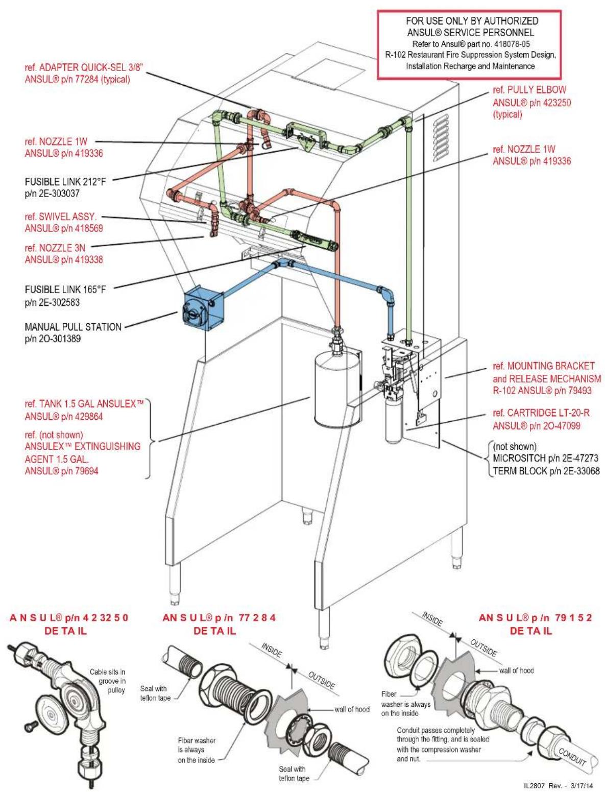
Two FUSIBLE LINKS are utilized for automatic actuation of the fire suppression system. Additionally, the hood is supplied with a MANUAL PULL STATION, which must be set-up at the time of installation by an authorized Ansul® distributor.
The MANUAL PULL STATION allows for for manual emergency shutdown of cooking appliance power, and actuation of the fire suppression system.
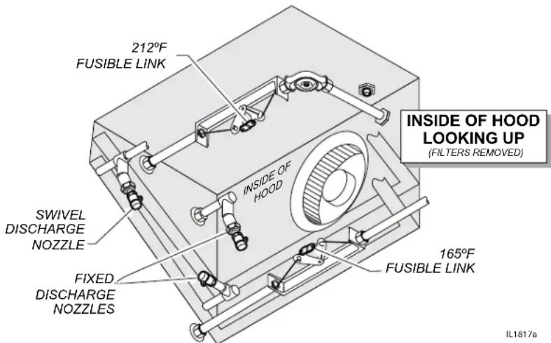
Three NOZZLES disperse the fire suppression media. Two inner nozzles protect the fan and plenum. The third, front mounted, nozzle is swivel mounted, and must be directed toward the cooking surface of the installed cooking appliance.
If the ventilator is situated such that the supplied manual pull station cannot be installed or is not readily accessible, a REMOTE MANUAL PULL STATION may be required by local codes. Any such remote manual pull station must be installed by an authorized Ansul® distributor in accordance with the AUTHORITYHAVINGJURISDICTION
When the fire suppression system discharges, the cooking appliance contactor is de-energized; and, the fire suppression media is discharged. Fire suppression media will form an emulsion designed to both smother and cool the fuels in/on the cooking appliance.
Two fusible links are used to detect fire. One (165°F) is located between the grease baffle and filter pack, and is for protection from a cooking appliance fire. The other (212°F) is located in the filter plenum, and will protect against a fire in the plenum. Either link melting will discharge the fire suppression media through all nozzles, disable the cooking appliance and cause a buzzer to sound.
The MANUAL PULL STATION and any similar REMOTE MANUAL PULL STATION will activate the fire suppression system when the ring on the pull station is pulled to its full extent.

DANGER FIRE HAZARD
Fire suppression system must be charged and certified by an authorized Ansul® distributor.
DO NOT attempt to modify or bypass the fire suppression system.
An uncontrolled fire can cause serious injury or death.
NOTE:
If the fire suppression system is discharged, a buzzer will sound continuously. The unit will remain inoperable until the fire suppression system is serviced, recharged and reset by an authorized Ansul® distributor.
Charging of the Ansul® Fire Suppression system must be in accordance with Ansul® Design, Installation, Recharge and Maintenance Manual, #418087.
NOTE:
If a REMOTE MANUAL PULL STATION is installed, moving the ventilator for any reason may cause the Ansul® system to discharge.
DANGER BURN HAZARD
Any additional remote pull station must NOT be installed on the front of the cooking appliances, nor forward of the ventilator side panels.
Discharge of the fire extinguishing system into hot grease or oil may cause hot foam to spill over from the cooking surface or frypot.
Serious burns and other injuries can result from contact with hot oil and from slipping in spilled oil.
Manual pull station is factory installed on the left side (facing the unit. It may, however, be relocated to the right side of the ventilator hood by an authorized Ansul® agent.
INSTALLATION (continued)
NOTE:
The GREASE BAFFLE and FILTER PACK actuate position switches when they are properly positioned. They must be properly installed for the under hood cooking appliance contactor to be energized.

CAUTION SLIP AND FALL HAZARD
DO NOT operate any cooking appliance unless the grease cup is installed.
Moisture dripping onto floor can cause a slip and fall hazard.
FILTER INSTALLATION
- Release two catches holding control panel/filter access panel. Lift the panel and raise the Prop Panel Rod to support and secure the panel in the raised position.
- Note air flow direction arrow on filter pack. Remove old filter pack and slide new filter pack fully into the appropriate slot. Verify that the airflow arrow points toward the fan. Use the provided handle to raise and lower the filter pack.
- Raise the panel and put the Prop Panel Rod back to its lowered position, then lower the panel and secure the catches.
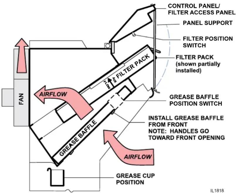
GREASE BAFFLE and GREASE CUP INSTALLATION
- Install grease baffle from front. Engage the baffle in the retainer slot. Push up until the baffle bottom clears the lower lip of the retainer, then lower the baffle into the bottom retainer
- Install GREASE CUP into brackets below grease baffle.
Note: Failure to install GREASE CUP will allow grease and moisture from GREASE BAFFLE to drop into hot cooking surfaces, creating both a SAFETY HAZARD (hot oil splatter) and a HEALTH HAZARD (contamination of the cooking surface or cooking oil).
OPERATION
Control Panel
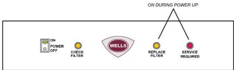
flowchart
graph TD
    A["ON POWER OFF"] --> B["CHECK FILTER"]
    B --> C["WELLS"]
    C --> D["ON DURING POWER UP"]
    C --> E["REPLACE FILTER"]
    C --> F["SERVICE REQUIRED"]
IL1820
NOTE: Cooking appliances must be operated in accordance with the manufacturer's instructions.
During normal operation, VENTILATOR POWER ON (illuminated power switch) will be the only light on the control panel that will be ON, when the unit is operating properly.
If the CHECK FILTERS light illuminates, check both GREASE BAFFLE and the HEPA AIR FILTER for proper installation.
If REPLACE FILTER light illuminates, replace FILTER PACK.
NOTE: REPLACE FILTERS light is a warning that filter pack is nearing the end of its service life. The ventilator will continue to operate for a period of time after REPLACE FILTER LIGHT turns ON to allow continued operation through a peak period. However, filter pack must be replaced within a short time period or it will clog, disabling the ventilator.
If SERVICE REQUIRED light illuminates, filter pack is restricted to the point of insufficient airflow for proper operation or a malfunction has occurred. Ventilator is shut down until the underlying clogged filter situation has been corrected. Replace clogged item with a fresh filter pack to correct the condition. Reset the unit by turning VENTILATOR POWER SWITCH to OFF, then back to ON. If the SERVICE REQUIRED light remains on, contact a Wells Authorized Service Agent.
A failure of incoming electric power will cause a shut down of the unit. Reset the unit by turning VENTILATOR POWER SWITCH to OFF, then back to ON.
Operation Lights
There are two equipment lights that will be on during normal operation.

CAUTION: HOT SURFACE
Exposed surfaces can be hot to the touch and may cause burns.
IMPORTANT:
The cooking appliance control relay are disabled when SERVICE REQUIRED light is illuminated. Note that the ventilator cannot operate if the filter pack is removed.
It is the responsibility of the store management to maintain sufficient spares of filter packs to avoid prolonged shutdown of the ventilator when this filter is expended.
Filter packs cannot be cleaned.
Wells Manufacturing assumes no liability for loss of business due to filter related shutdown.
CLEANING INSTRUCTIONS

CAUTION: HOT SURFACE
Exposed surfaces can be hot to the touch and may cause burns. Allow unit to cool before cleaning.
PRECAUTIONS: Allow to cool Cover frypot to prevent oil contamination
FREQUENCY: Weekly
TOOLS: Mild detergent, clean non-abrasive towels
NOTE: Ventilator section to be cleaned in conjunction with cooking appliance. Refer to appliance user instructions for cleaning procedure.
- Disconnect unit from electric power and allow to cool. Cover cooking appliance to prevent oil contamination.
- Remove GREASE BAFFLE, GREASE CUP.
- Empty GREASE CUP into an appropriate grease collection receptacle.
- Clean GREASE BAFFLE, GREASE CUP and in a sink or dishwasher using mild detergent and warm water.
- Dry components with a clean non-abrasive cloth. Reinstall GREASE BAFFLE, GREASE CUP in ventilator.
- Wipe exterior of ventilator with a clean cloth moistened with warm water and mild detergent. Rinse by wiping with a clean cloth moistened with warm water.
- Uncover the cooking appliance and reconnect unit to electric power.
Procedure is complete
CLEANING INSTRUCTIONS
PRECAUTIONS: Allow to cool
Cover cooking surfaces and frypots to prevent contamination.
FREQUENCY: Monthly
TOOLS: Mild detergent, clean non-abrasive towels
NOTE: Ventilator section to be cleaned in conjunction with cooking appliance. Refer to appliance user instructions for cleaning procedure.
- Disconnect unit from electric power and allow to cool. Cover cooking appliance to prevent oil contamination.
- Remove GREASE BAFFLE, GREASE CUP, and FILTER PACK.
- Wipe interior of ventilator with a clean cloth moistened with warm water and mild detergent. Rinse by wiping with a clean cloth moistened with warm water. DO NOT clean by spraying.
- Dry ventilator thoroughly with a clean non-abrasive cloth. Reinstall FILTER PACK, GREASE BAFFLE, GREASE CUP.
- Uncover the cooking appliance and reconnect unit to electric power.
Procedure is complete

CAUTION: HOT SURFACE
Exposed surfaces can be hot to the touch and may cause burns. Allow unit to cool before cleaning.
CAUTION: SHOCK HAZARD
DO NOT splash or pour water or grease onto control panel.
IMPORTANT:
DO NOT wash FILTER PACK. Washing these filters will clog them, and cause installed cooking appliance to be disabled.
IMPORTANT:
DO NOT clean interior of ventilator by pressure spraying.
Spraying can contaminate the cooking appliance, and may cause internal damage to the ventilator blower, operation proofing system and/or fire suppression system.
Clean by wiping only.
TROUBLESHOOTING SUGGESTIONS
| Problem Possible Cause Suggested Remedy | ||
| Unit will not operate(no indicators lights lit) Reset circuit breaker for unit | Disconnected from electric power | |
| Unit will not operate(buzzer sounds) | Fire suppression system not set Contact an authorized Ansu® distributor for repairs | |
| CHECK FILTER light lit | Filter pack or grease baffle not in position | Properly install filter pack and grease baffle |
| REPLACE FILTER light lit | Filter pack nearing end of service life | Arrange to replace filter pack in a timely manner |
| SERVICE REQUIRED light lit (cooking appliance not operating) | Filter pack plugged Replace filter pack | |
| Fire damper in exhaust collar has closed | Contact an authorized Wells service agent for repairs | |
| One or more vacuum sensing lines or ports plugged, or sensing line dislodged. | Contact an authorized Wells service agent for repairs | |
| NOTE: If, after 10 seconds, there is insufficient airflow for proper operation, SERVICE REQUIRED light will illuminate and under-hood appliance (s) will be de-energized.Press VENTILATOR POWER SWITCH to OFF, then back to ON to reset system. | ||
NOTE:
FILTERS are the only user serviceable components in this ventilator hood system. For all problems that cannot be remedied by servicing the filters, contact:
Ventilator section - authorized Wells service agency
Fire suppression system - authorized Ansul® distributor
IMPORTANT:
Contact ANSUL® for fire suppression system installation, set-up and service:
Ansul Incorporated 1-800-TO-ANSUL (1-800-862-6785)
One Station Street
Marinette, WI 54143-2542 website http://www.ansul.com
IMPORTANT:
Parts used in the Ansul® fire suppression system are not serviceable by the owner/operator.
Procedures for servicing fire suppression equipment are described in:
ANSUL® R-102 SYSTEM DESIGN, INSTALLATION, RECHARGE AND MAINTENANCE MANUAL (418087, current edition)
NOTE:
ANSUL® Manual 41807 and Wells Bulletin 301646 are intended for use by authorized Ansul® service personnel only.
USE AND MAINTENANCE SHALL BE IN ACCORDANCE WITH THE STANDARD FOR VENTILATION CONTROL AND FIRE PROTECTION OF COMMERCIAL COOKING OPERATIONS, N.F.P.A. 96 (current edition).
3-MONTH MAINTENANCE:
Thoroughly clean entire HOOD PLENUM and BLOWER section.
6-MONTH MAINTENANCE:
Inspection and testing of total operation including FIRE DAMPER and all SAFETY INTERLOCKS shall be performed by qualified service personnel.
All FIRE SUPPRESION SYSTEM actuation components including MANUAL PULL STATION and any REMOTE MANUAL PULL STATION must be inspected for proper operation in accordance with the maintenance schedule published in ANSUL® R-102 SYSTEM DESIGN, INSTALLATION, RECHARGE AND MAINTENANCE MANUAL (418087).
ANNUAL (12-MONTH) MAINTENANCE:
FIRE SUPRESSION SYSTEM FUSIBLE LINKS must be replaced.
NOZZLES and MANUAL PULL STATION must be cleaned in accordance with ANSUL® R-102 SYSYTEM DESIGN, INSTALLATION, RECHARGE AND MAINTENANCE MANUAL (418087).
12-YEAR MAINTENANCE:
The FIRE SUPRESSION AGENT TANK must be HYDROSTATICALLY TESTED, and the FIRE EXTINGUISHING AGENT must be REPLACED in accordance with the maintenance schedule published in ANSUL® R-102 SYSTEM (STANDARD UL 300 LISTED). This maintenance to be performed by qualified Ansul® service personnel only.
IMPORTANT:
Per NFPS 96, a signed and dated VENTILATOR HOOD MAINTENANCE LOG must be maintained on the premises, and be made available for inspection by the authority having jurisdiction upon request.
IMPORTANT:
Should the fire suppression system discharge, all lines and nozzles must be thoroughly cleaned prior to recharging the system.
Be sure to note such cleaning on the hood maintenance log. Residual fire suppression media may compromise the flow and dispersion of fire suppression media in any subsequent activation.
Inspection shall be conducted on a monthly basis in accordance with the manufacturer's Operation Manual. At a minimum, this inspection shall include verification of the following:
WELLS BLOOMFIELD, LLC
D OWNERS MONTHLY INSPECTION LOG
| OPERATION AGENT DATE | |||||||||||||
| Extinguishing system components:In proper place and (visually ingood order | |||||||||||||
| Manual pull station actuators for firesuppression system are obstructed | |||||||||||||
| The maintenance log is in placeand up to date | |||||||||||||
| No obvious physical damage or conditionexists that might prevent operation of thefire suppression system | |||||||||||||
| The nozzle blow-off caps are in placeand in good condition | |||||||||||||
| The hood, duct and protection cookingappliance have not been replaced,modified or relocated | |||||||||||||
| Clean plenum GREASE BAFFLE andBLOWER (max. interval: 3 months) | |||||||||||||
| Change PRE-FILTER and FILTER PACK(as required) | |||||||||||||
II 2144
This MAINTENANCE LOG is to be performed and completed by a trained technician who has completed the instruction necessary to perform the maintenance and recharge service.
WELLS BLOOMFIELD, LLC
VENTILATOR HOOD MAINTENANCE LOG
| OPERATION | AGENT / DATE | ||||||||||
| Clean and inspect discharge nozzle in plenum BEFORE filtersMax. interval: 6 months | |||||||||||
| Clean and inspect discharge nozzle in plenum AFTER filtersMax. interval: 6 months | |||||||||||
| Inspect fire suppression fuse links, all releasing devices for actuation, fire suppressant tank liquid levelMax interval: 6 months (discharge of fire suppressant not a part of this test) | |||||||||||
| Inspect fire suppression hoses, plumbing and tank for obstructions and any conditions such as, but not limited to, corrosion and pitting.Max. interval: 6 months | |||||||||||
| Inspect and test all filter interlocksMax. interval: 6 months | |||||||||||
| Replace two (2) fire suppressionlinks at cooking appliance:each link is rated @ 165°FMax interval: 12 months | Log TEMP | ||||||||||
| Log Mfg DATEStamp | |||||||||||
| Replace fire damper fusible link:rated @ 280°FMax interval: 12 months | Log TEMP | ||||||||||
| Log Mfg DATEStamp | |||||||||||
THIS MAINTENANCE LOG MUST BE KEPT IN A PROTECTIVE COVER PERMANENTLY ATTACHED TO THE APPLIANCE IL2145
Log all repairs and recommendations on reverse side. Any repairs, other than replacement of factory authorized parts, to the fire suppression plumbing system must be
subject to hydrostatic pressure testing.
ANSULEX Low pH
QUICK IDENTIFIER (In Plant Common Name)
| Manufacturer's Name: | ANSUL INCORPORATED | Emergency Telephone No.: | CHEMTREC (800) 424-9300 or (703) 527-3887 |
| Address: | One Stanton Street, Marinette, WI 54143-2542 | Other Information Calls: | (715) 735-7411 |
| Prepared By: | Safety and Health Department | Date Prepared: | February 1, 1999 |
SECTION 1 - IDENTITY
| Common Name (Used on Label): (Trade Name and Synonyms) | ANSULEX Low pH Liquid Fire Suppressant | CAS No.: | N/A | |
| Chemical Name: | N/A This is a Mixtu re | Chemical Family: | Mixture | |
| Formula: | N/A | |||
SECTION 2 - INGREDIENTS
| PART A - HAZARDOUS INGREDIENTS | ||||
| Principal Hazardous Component(s) (chemical and common name(s)): | Wt.% | CAS No. | ACGIH TLV | Acute Toxicity Data |
| None | N/A N/A N/A N/A | |||
| PART B - OTHER INGREDIENTS | ||||
| Other Component(s) (chemical and common name(s)): | Wt.% | CAS No. | ACGIH TLV | Acute Toxicity Data |
| Proprietary Mixture of Organic and Inorganic Salts | 48.0 - 50.0 | N/A | N/E | NDA |
| Phosphoric Acid 0.2 | 7664-38-2 | N/E | NDA | |
| EDTA | 0.65 | 64--02-8 | N/E | NDA |
| Yellow-Green Fluorescent Dye 0.011 | 518-47-8 | N/E | Oral LD (rat) 6800 mg/kg | |
| Water | Approx. 50.0 | 7732-18-5 | N/E | NDA |
SECTION 3 - PHYSICAL AND CHEMICAL CHARACTERISTICS (Fire and Explosion Data)
| Boiling Point: | 113°C | Specific Gravity (H2O=1): | 1.33 | Vapor Pressure (mm Hg): | Not Determined | ||
| Percent Volatile by Volume (%): | Approx. 50.0 | Vapor Density: (Air = 1): | 1.03 | Evaporation Rate: (Butyl Acetate=1): | Approx. 0.005 | ||
| Solubility in Water: | 100% | Reactivity in Water: | Mild exothermic reaction | ||||
| Appearance and Odor: | Fluorescent Yellow Colored Liquid, Mild Odor | ||||||
| Flash Point: | None to boiling | Flammable Limits in Air % by Volume: | N/A | Extinguisher Media: | N/A N/A | Auto-Ignition Temperature: | |
| Special Fire Fighting Procedures: | NONE - THIS IS AN EXTINGUISHING AGENT | ||||||
| Unusual Fire and Explosion Hazards: | None | ||||||
SECTION 4 - PHYSICAL HAZARDS
| Stability: | UnstableStable | Conditionsto Avoid: | N/A |
| Incompatibility(Materials to Avoid): | Reactive Metals, CIF_3 electrically energized equipment, any material reactive with water. | ||
| Hazardous Decomposition Products: | Not established, acrid fumes. | ||
| Hazardous Polymerization: | May OccurWill N of Occur | Conditionsto Avoid: | N/A |
SECTION 5 - HEALTH HAZARDS
ANSULEX Low pH (continued)
| ThresholdLimit Value: | None Established | ||||
| Routes of Entry:Eye Contact: | Irritant | ||||
| Skin Contact: | Irritant | ||||
| Inhalation: | Not an expected route of entry. Can be irritating to mucous membranes. | ||||
| Ingestion: | Irritating to mucous membranes. Acute Oral LD (Sprague-Dawley rats) 825.5mg/kg. | ||||
| Signs and Symptoms: | Acute Exposure: Material irritates skin, eyes, and mucous membranes.Chronic Exposure: None known. | ||||
| Medical Conditions Generally Aggravated by Exposure: | None known. | ||||
| Chemical Listed as Carcinogen or Potential: | National Toxicology Yes ☐ I.A.R.C Yes ☐ OSHA Yes ☐ Program: No ☒ Monographs: No ☒ No ☒ | ||||
SECTION 6 - EMERGENCY AND FIRST AID PROCEDURES
| Eye Contact: | Flush and irrigate with water for 15 minutes while holding eyelids open.If irritation persists, seek medical attention. |
| Skin Contact: | Wash thoroughly with soap and water. If irritation persists, seek medical attention. |
| Inhalation: | Fresh air if symptoms occur. If irritation persists, seek medical attention. |
| Ingestion: | Dilute by drinking large quantities of water. |
SECTION 7 - SPECIAL PROTECTION INFORMATION
| Respiratory Protection(Specify Type): | N/A | |||
| Ventilation: | Local Exhaust: | N/A N/A | Mechanical (General): | |
| Protective Gloves: | Rubber gloves for spill/leak | Eye Protection: | Chemical goggles recommended during spill/leak procedures. | |
| Other Protective Clothing or Equipment: | Eye wash and safety showers are good safety practice. | |||
SECTION 8 - SPECIAL PRECAUTIONS AND SPILL/LEAK PROCEDURES
| Precautions to be taken in Handling and Storage: | Store in original container. Keep tightly closed. Keep separate from acid. |
| Other Precautions: | See incompatibility information in Section 4. |
| Steps to be taken in Case Material is Released or Spilled: | Stop leaks. Contain spills. Remove as much as possible. Place in closed container for proper disposal Wash spill area with large amounts of water to remove traces and neutralize. |
| Waste Disposal Methods: | Dispose of in compliance with local, state and federal regulations. |
HAZARDOUS MATERIAL IDENTIFICATION SYSTEM
| HAZARD INDEX | |
| 4 SEVERE HAZARD | 0 HEALTH |
| 3 SERIOUS HAZARD | |
| 2 MODERATE HAZARD | 0 FLAMMABILITY |
| 1 SLIGHT HAZARD | |
| 0 MINIMAL HAZARD | 0 REACTIVITY |
N/A = Not Applicable NDA = No Data Available N/E = Not Established
ANSUL and ANSULEX are registered trademarks.
Internet Address: http://www.ansul.com
ANSUL INCORPORATED, ONE STANTON STREET, MARINETTE, WI 54143-2542
Form No. F-90160-6
©1989 Ansul Incorporated
WIRING DIAGRAM
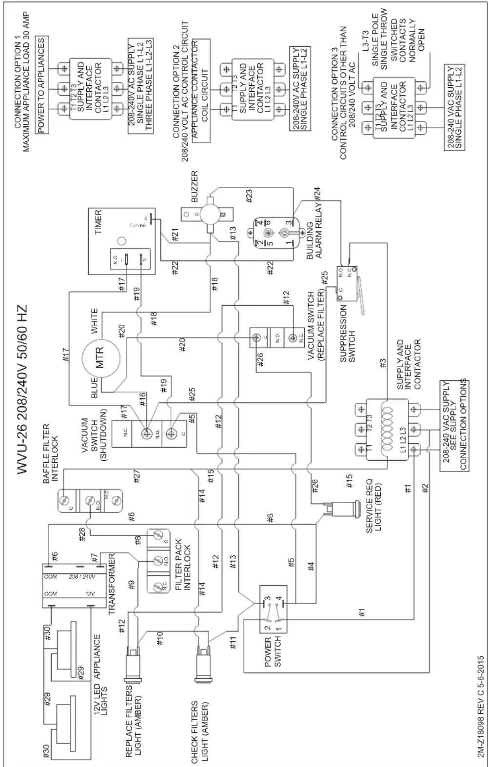
flowchart
graph TD
    A["WVU-26 208/240V 50/60 HZ"] --> B["POWER SWITCH"]
    B --> C["TRANSFORMER"]
    C --> D["REPLACE FILTERS LIGHT (AMBER)"]
    C --> E["CHECK FILTERS LIGHT (AMBER)"]
    B --> F["POWER SWITCH"]
    F --> G["SERVICE REQ LIGHT (RED)"]
    G --> H["208-240 VAC SUPPLY SEE SUPPLY CONNECTION OPTION$"]
    H --> I["208-240 VAC SUPPLY SINGLE PHASE L1-L2"]
    H --> J["SUPPLY AND INTERFACE CONTACTOR"]
    J --> K["L1 L2 L3"]
    K --> L["208-240 VAC SUPPLY SEE SUPPLY CONNECTION OPTION$"]
    L --> M["208-240 VAC SUPPLY SINGLE PHASE L1-L2"]
    N["CONNECTION OPTION 1 MAXIMUM APPLIANCE LOAD 30 AMP"] --> O["T1 T2 T3 SUPPLY AND INTERFACE CONTACTOR L1 L2 L3"]
    O --> P["208-240V AC SUPPLY SINGLE PHASE L1-L2"]
    N --> Q["CONNECTION OPTION 2 208/240 VOLT AC CONTROL CIRCUIT APPLIANCE CONTACTOR COIL CIRCUIT"]
    Q --> R["208-240V AC SUPPLY SINGLE PHASE L1-L2"]
    N --> S["CONNECTION OPTION 3 CONTROL CIRCUITS OTHER THAN 208/240 VOLT AC"]
    S --> T["L3-T3 SINGLE POLE SINGLE THROW SWITCHED CONTACTS NORMALLY OPEN"]
    T --> U["208-240 VAC SUPPLY SINGLE PHASE L1-L2"]
M521 p/n 2M-Z18099 OpM WVU- Universal Hood
EXPLODED VIEW: WVU-26
MAINTENANCE COMPONENTS
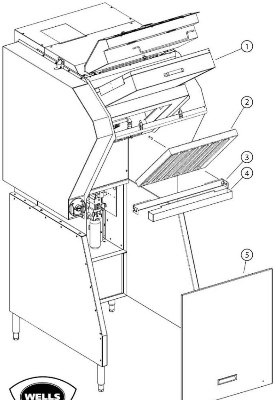

SK2766, Rev. - 3/17/14
Model: WVU26 Maintenance Parts
| Fig No. Part No Description | |
| 1 N1-307923 FILTER ASSY WVU | |
| 2 2I-Z19216 FILTER BAFFLE GREASE WVU | |
| 3 N1-Z18095 BRACKET, GREASE TRAY | |
| 4 N1-Z13496 TRAY, GREASE | |
| 5 N1-WL0586 ASM. ANSUL ACCESS DOOR | |
EXPLODED VIEW: WVU-26
MAIN ASSEMLBY
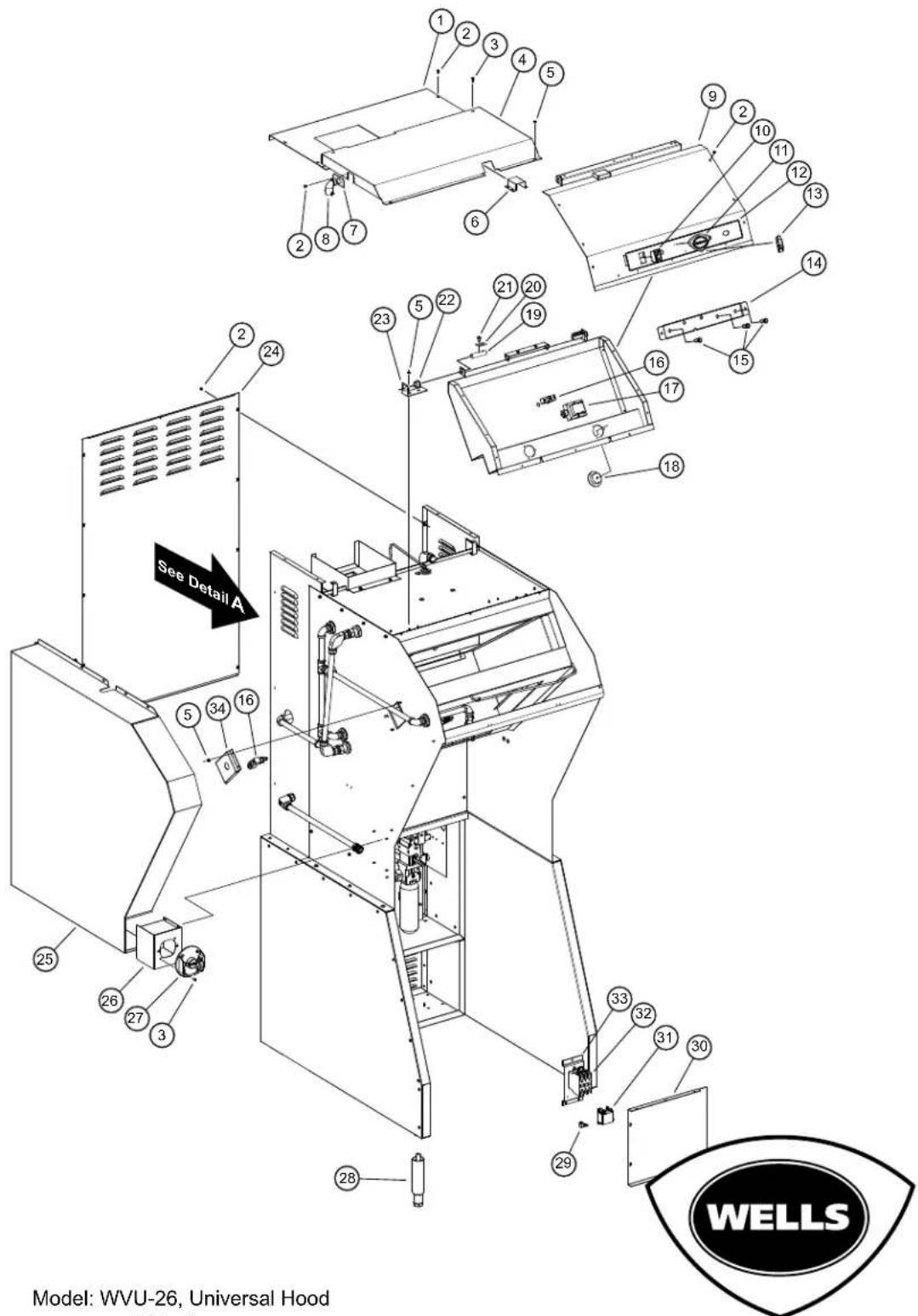
SK2767, Rev. A 7/23/15
PARTS LIST: WVU-26 MAIN ASSEMBLY
MAIN ASSEMBLY
| Model: WVU-26 Main Assy | |||
| Fig No | Part No Qty Description | ||
| 1 N1- | WL0581 1 PANEL,TOP | REAR ASSY | |
| 2 2C- | 35487 43 SCREW 8-32 | X5/16 PH TR HD | |
| 3 2C- | 31730 86 SCREW 8-32 | X1/2 PH TR HD M | |
| 4 N1- | Z18088 1 PANEL, TOP | COVER | |
| 5 2C- | 31053 50 NUT 8-32 KE | PS MS NICKEL | |
| 6 N1- | Z13472 1 COVER, WIRE | TOP PANEL | |
| 7 N1- | Z13491 1 PLATE, CON | DUIT MOUNT | |
| 8 CONDUIT | |||
| 9 N1- | WL0579 1 PANEL,CONTROL | TOP ASSY | |
| 10 2E- | 305295 1 SWITCH RO | CKER 250V 10A GR | |
| 11 2M- | 306719 1 LOGO WEL | LS DIECAST SHIELD | |
| 12 2M- | Z18096 | I GRAPHIC PANEL, WVU-26 | |
| 13 2C- | 307939 | 2 LATCH DRAW SS | |
| 14 N1- | Z18102 1 MNT.PLATE | ,CONTROL LIGHTS | |
| 15 N1- | WL0281 3 LED CLEAR | W/ TERM ASSY. | |
| 16 2E- | 300407 2 SWITCH MAN | NUAL ADVANCE ROT | |
| 17 2E- | Z15018 | I TRANSFORMER, 208/240 12V | |
| 18 2E- | Z14669 | 2 LED FLOODLIGHT, 45W CW | |
| 19 2A- | 305610 2 PIN HINGE | DOOR Ovens | |
| 20 N1- | Z13521 2 PLATE, PIN | HINGE | |
| 21 2C- | 40612 16 SCREW 1/4 | 20X1/2 SL TR MS | |
| 22 2K- | 305619 2 BUSHING U | PPER DOOR HINGE | |
| 23 N1- | Z13471 2 BRACKET, | HINGE | |
| 24 N1- | Z18092 1 REAR PANEL | ||
| 25 N1- | WL0125 1 COVER AS | SY, LEFT PLUMBING | |
| 26 N1- | WL0126 1 BOX, MANUAL PULL ASSEMBLY | ||
| 27 2O- | 308131 1 REMOTE PULL STATION RED | ||
| 28 2A- | 307628 4 LEG 6 ADJ | 1/2-13 SS | |
| 29 2C- | 307288 | LUG GROUND SOLDERLESS 2-1 | |
| 30 N1- | Z18085 1 COVER,ELECTRICAL BOX | ||
| 31 2E- | 44514 | RELAY 208/240V COIL | |
| 32 2E- | Z14960 | CONTACTOR, 40A | |
| 33 N1- | Z13423 1 CONTACT MOUNTING BRACKET | ||
| 34 N1- | Z13464 1 SWITCH BOX COVER | ||
PARTS LIST: WVU-26
Main Assembly; Detail A
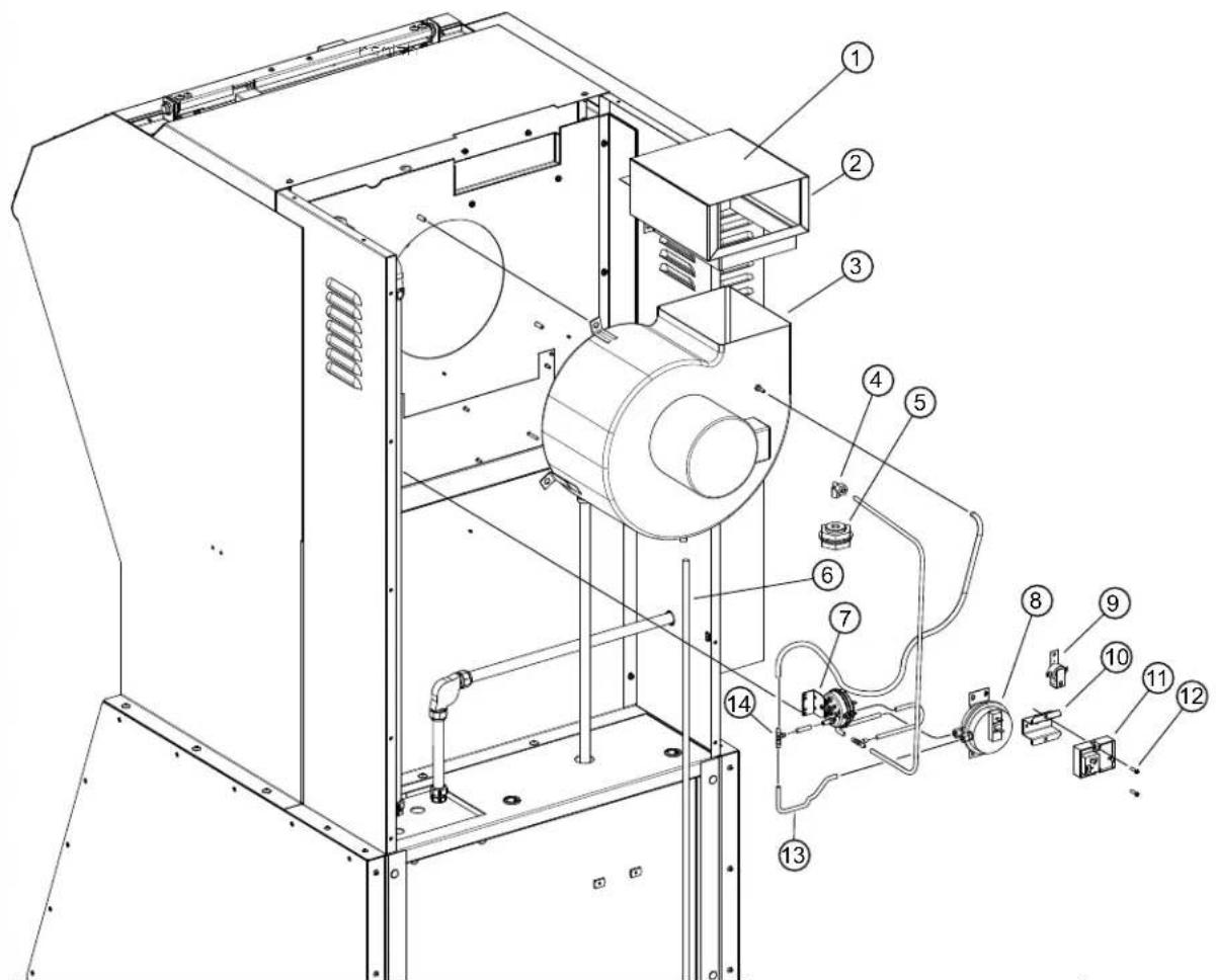
Model: WVU-26 DETAIL A
| Fig No Part Number Qty Description |
| 1 M3-301193 1 SCREEN BLOWER COVER |
| 2 N1-WL0117 1 DAMPER CAGE ASSY |
| 3 2U-Z14025 1 BLOWER ASSY 208/240 1P CW |
| 4 2K-301429 1 FTG COMPRESSION MALE ELBO |
| 5 2k-47100 1 ADAPTER 1/4IN QUICK CON |
| 6 N1-Z13713 1 TUBE SIL.375ID X 60" |
| 7 2E-Z17173 1 VACUUM SWITCH,REPLACE |
| 8 2E-301379 1 VACUUM SWITCH, SHUTDOWN |
| 9 2J-44834 1 BUZZER 220V ROHS |
| 10 N1-Z17349 1 BRACKET, TIMER ADAPTER |
| 11 2P-Z17415 1 TIMER,CUBE/ RELAY |
| 12 2C-08-07-0042 2 SCREW 8-32X5/8 RHP STL NP |
| 13 2J-302629 by foot HOSE .18" ID - .31"OD, Sold by Foot |
| 14 2K-302630 2 TEE NYLON 3/16 |
DETAIL A
WVU-26

SK2768, Rev. - 3/19/14
ANSUL® SYSTEM COMPONENTS
SERVICE TRAINING - QUALITY SERVICE

CUSTOMER SATISFACTION
- OWNER'S MANUAL
- VENTLESS UNIVERSAL
- MODULAR HOOD SYSTEM
- MODEL
- WVU-26
- IMPORTANT: DO NOT DISCARD THIS MANUAL
- LIMITED EQUIPMENT WARRANTY
- THIS WARRANTY IS SUBJECT TO ALL LISTED CONDITIONS.
- CONTACT
- WARRANTY EXCLUSIONS
- ADDITIONAL WARRANTIES
- TABLE OF CONTENTS
- INTRODUCTION
- ELECTRICAL SPECIFICATIONS
- UNDER-HOOD APPLIANCE LIMITATIONS:
- WARNINGS - ENGLISH
- DANGER FIRE HAZARD
- WARNING:
- NOTE:
- DANGER - DO NOT BLOCK ACCESS TO THE FIRE EXTINGUSHING MANUAL PULL.
- DANGER: SUFFOCATION HAZARD
- WARNING: SHOCK HAZARD
- WARNING: RISK OF INJURY
- SLIP AND FALL HAZARD
- WARNINGS - FRENCH
- IMPORTANT : NE JETEZ PAS CE MANUEL
- PRECAUTIONS AND GENERAL INFORMATION
- IMPORTANT:
- AGENCY LISTING INFORMATION
- INSTALLATION
- UNPACKING & INSPECTION
- COMPONENTS
- INSTALLATION (continued)
- SERVICE TECHNICIAN INSTALLATION NOTES
- SETUP
- DANGER:
- SUFFOCATION HAZARD
- CAUTION: RISK OF DAMAGE
- WARNING SHOCK HAZARD
- CAUTION: FIRE HAZARD HEALTH HAZARD
- CAUTION: SHOCK HAZARD
- ELECTRICAL INSTALLATION
- SUPPLY CONNECTIONS
- FIRE SUPPRESSION SYSTEM INSTALLATION
- DANGER BURN HAZARD
- CAUTION SLIP AND FALL HAZARD
- FILTER INSTALLATION
- GREASE BAFFLE and GREASE CUP INSTALLATION
- OPERATION
- Control Panel
- Operation Lights
- CAUTION: HOT SURFACE
- CLEANING INSTRUCTIONS
- 3-MONTH MAINTENANCE:
- 6-MONTH MAINTENANCE:
- ANNUAL (12-MONTH) MAINTENANCE:
- 12-YEAR MAINTENANCE:
- WIRING DIAGRAM
- EXPLODED VIEW: WVU-26
- MAINTENANCE COMPONENTS
- PARTS LIST: WVU-26 MAIN ASSEMBLY
- PARTS LIST: WVU-26
- ANSUL® SYSTEM COMPONENTS
Brand : Wells
Model : WVU-26
Category : Range hood