
DIRLC3210S17W - Air Conditioning Panduit - Free user manual and instructions
Find the device manual for free DIRLC3210S17W Panduit in PDF.


| Product Type | Inlet Duct System for Cabinet Cooling |
| Brand | Panduit |
| Model | DIRLC3210S17W |
| Compatible Cabinets | Net-Access legacy CN*** and N-Type cabinets (42 RU and 45 RU) |
| Required Rail Spacing | 23.5 in to 25.5 in (front to rear) |
| Number of Switches Supported | Up to 2 switches per cabinet |
| Components Included | Upper and lower left/right brackets, side duct, upper and lower seal plates, upper and lower duct boxes, adjustment brackets, mounting hardware |
| Hardware Supplied | #12-24 screws, #12 star washers, M5 nuts, #10-32 nuts (for side duct) |
| Tools Required | Phillips head screwdriver, socket wrench, M8 socket |
| Installation Notes | Front equipment rails must be in full forward position; rear rails at 23.5-25.5 in from front; RU numbering from bottom (#1 at bottom); keep-out areas apply for legacy cabinets |
| Weight (estimated) | Approximately 5-10 lb (2.3-4.5 kg) depending on configuration |
| Material | Metal (steel) with foam seal |
| Use | Directs cold air from cold aisle to switch equipment, improving cooling efficiency |
Frequently Asked Questions - DIRLC3210S17W Panduit
User questions about DIRLC3210S17W Panduit
0 question about this device. Answer the ones you know or ask your own.
Ask a new question about this device
Download the instructions for your Air Conditioning in PDF format for free! Find your manual DIRLC3210S17W - Panduit and take your electronic device back in hand. On this page are published all the documents necessary for the use of your device. DIRLC3210S17W by Panduit.
USER MANUAL DIRLC3210S17W Panduit
natural_image
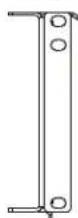
Technical line drawing of a rectangular metal bracket with mounting holes (no text or symbols)Upper LH Bracket
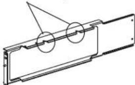
Note: Upper RH Bracket Has Notches On Top.
natural_image
Technical line drawing of a mechanical component with circular features and triangular cutouts (no text or symbols)Upper RH Bracket
natural_image
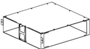
Isometric line drawing of a rectangular enclosure or storage unit with internal doors and windows (no text or symbols)Upper Inlet Duct Box
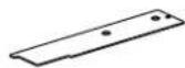
Upper Seal Plate
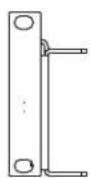
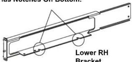
Lower LH Bracket
natural_image
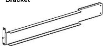
Technical line drawing of a mechanical bracket or support structure (no text or symbols)Note: Lower RH Bracket Has Notches On Bottom.
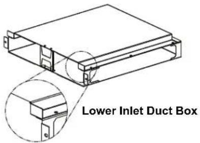
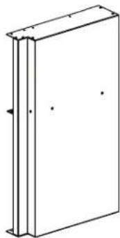
natural_image
Simple line drawing of a rectangular book or document with no text or symbols visibleSide Ducting
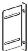
(2) Upper Adjustment Brackets
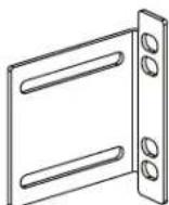
(2) Lower Adjustment Brackets
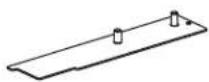
Lower Seal Plate
INDEX
PAGE
Upper / Lower Left Hand Bracket Installation.... 5
Upper / Lower Right Hand Bracket Installation.... 6
Attaching Foam Seal to Side Duct.... 7
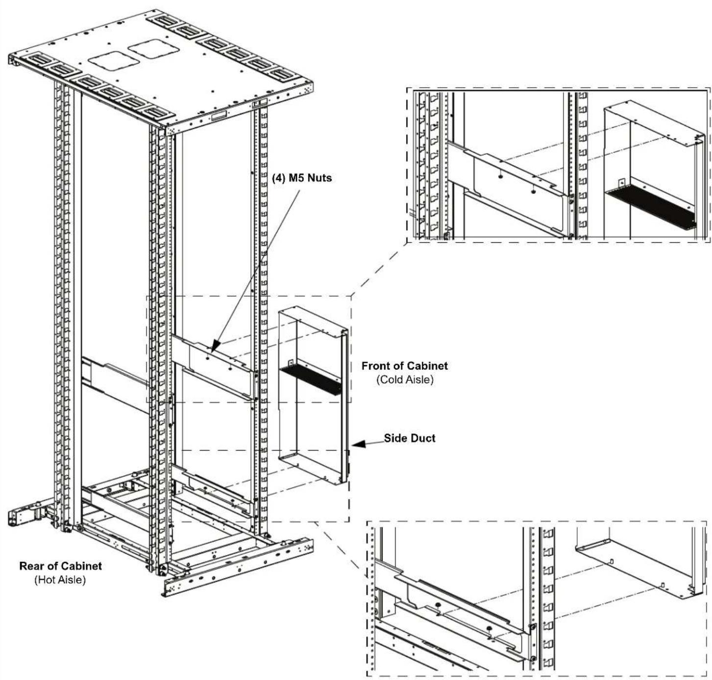
Side Duct Installation (Day 1: Without Side Panel)....8
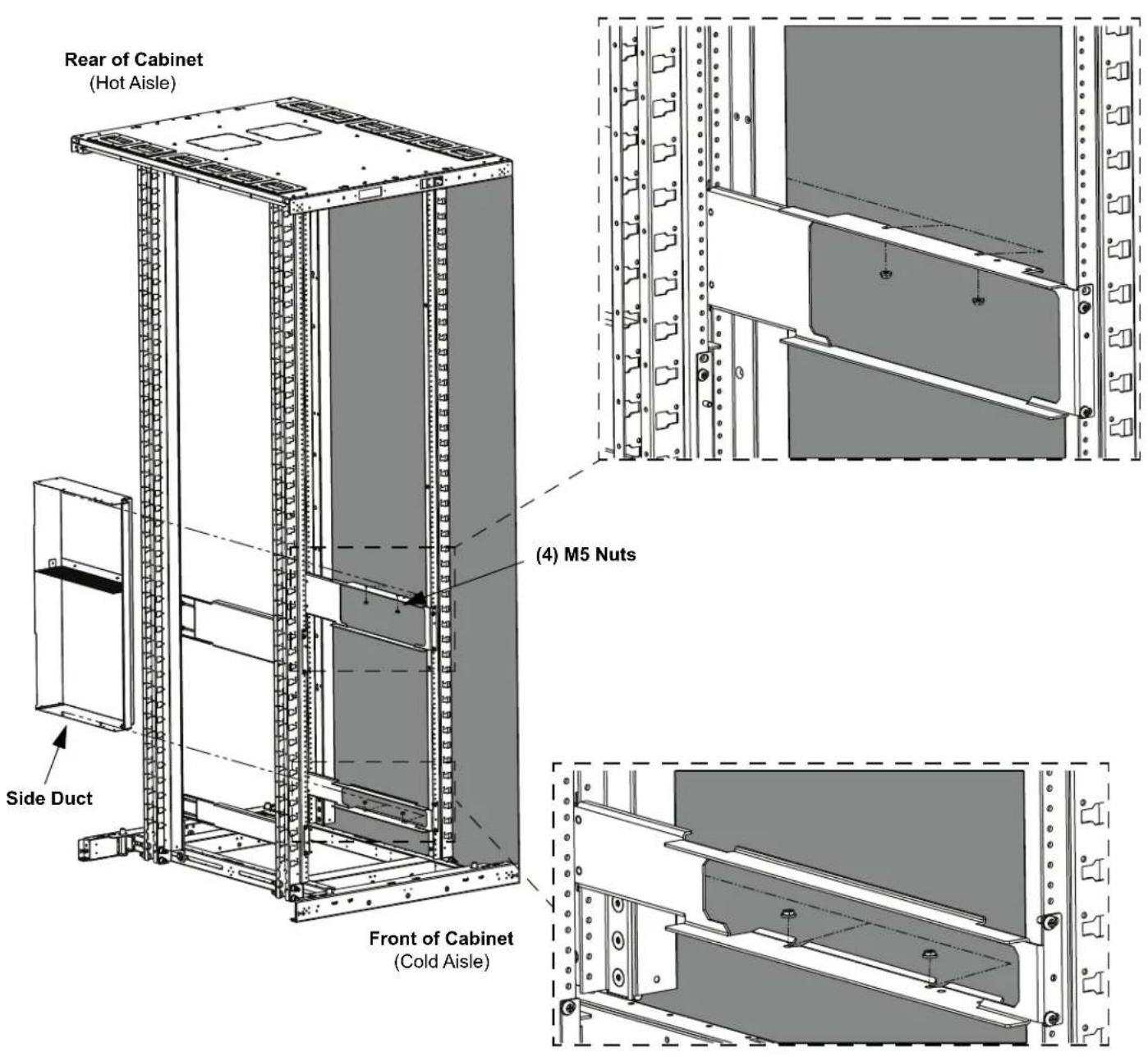
Side Duct Installation (Day 2: With Side Panel)....9
Upper / Lower Seal Plate Installation.... 10
Upper / Lower Duct Box Installation.... 11
Tools Needed:
-Phillips Head Screwdriver
-Socket Wrench
-M8 Socket
Hardware Supplied:

12 Star Washer
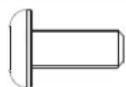
12-24
Screw

M5 Nut
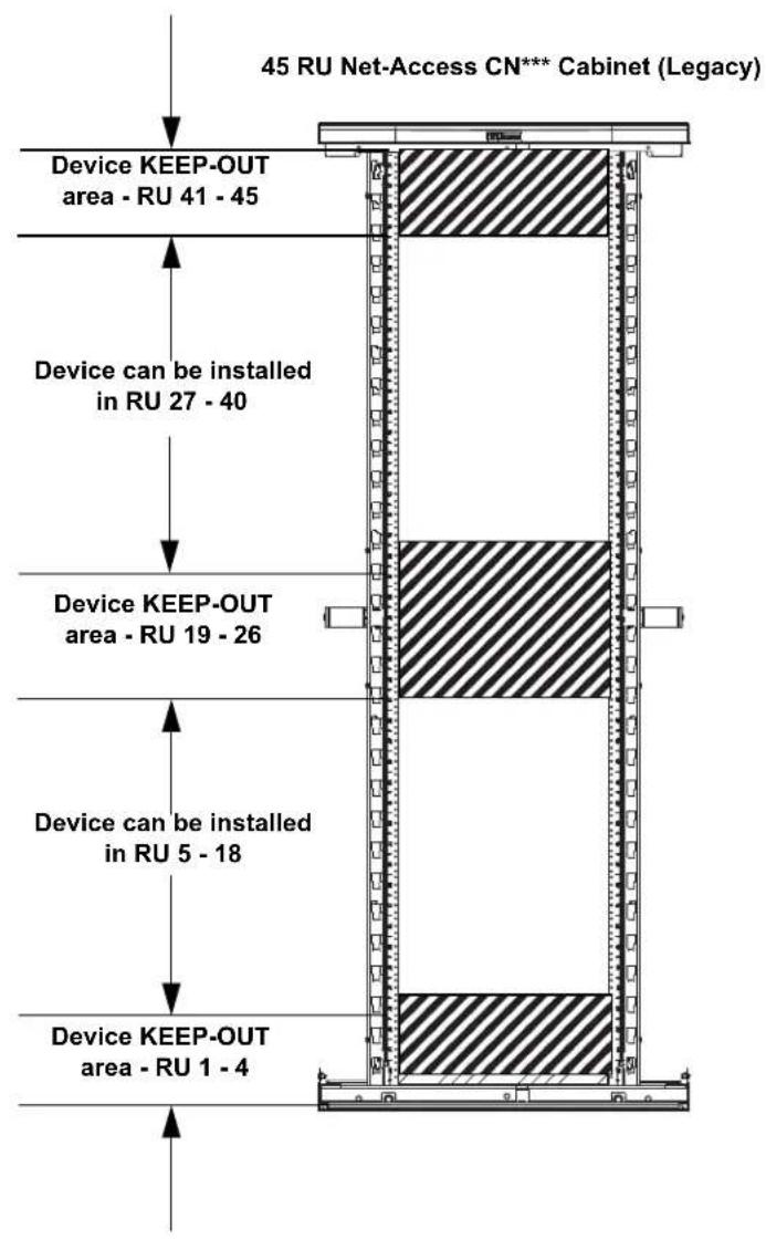
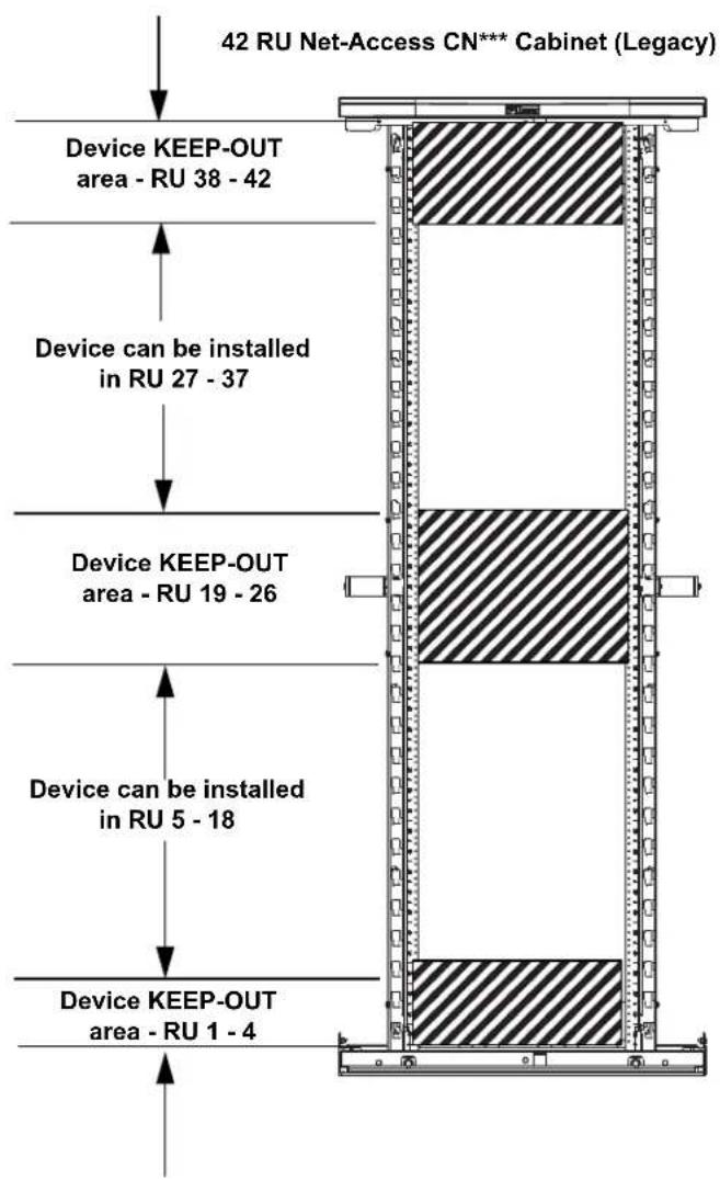
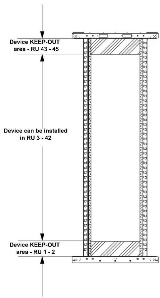
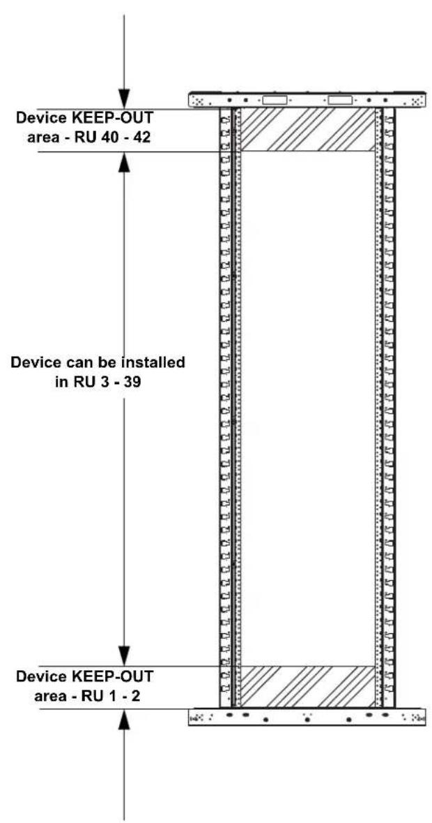
Device Placement
- Due to physical constraints posed by the front-to-back beams on the legacy Net-Access cabinet, there are certain areas of the cabinet that the device cannot be mounted when used in conjunction with this inlet duct.
- For new Net-Access switch cabinets (N***), there are no device keep-out areas. The only restriction on device is that 3 RU must be left open above and 2 RU must be left open below the switch.
• NOTES:
- Numbers-up RU numbering (#1 at bottom) assumed.
• The front equipment rails need to be in the full forward position. - Rear equipment rails need to be located 23.5" to 25.5" from the front rails.
For Technical Support: www.panduit.com/resources/install_maintain.asp
Device Placement for Net-Access N-Type Cabinets (N\*\*\* )
- For Net-Access N-Type cabinets front and rear equipment rails need to be 23.5" - 25.5" apart.
• NOTES:
• (2) switches are able to fit into both the 42 RU and 45 RU N-Type cabinets. - Numbers-up RU numbering (#1 at bottom) assumed.
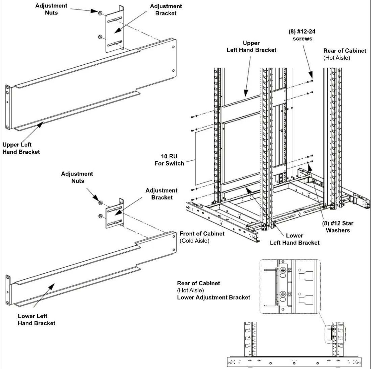
Upper / Lower Left Hand Bracket Installation
- The inlet duct system is designed to accommodate e-rail spacing between 23.5" to 25.5". A 4 post Cisco Nexus 7018 type rack mounting kit can be used as an alternative to the 6807 mounting kit.
• Measure distance between front and rear rails. - Loosen nuts on adjustment bracket and adjust to fit rail spacing.
• Install (1) Upper Left Hand Bracket with (4) #12-24 screws and (4) #12 star washers. (Leave screws loose until Inlet Box is installed.)
• Install (1) Lower Left Hand Bracket with (4) #12-24 screws and (4) #12 star washers. (Leave screws loose until Inlet Box is installed.)
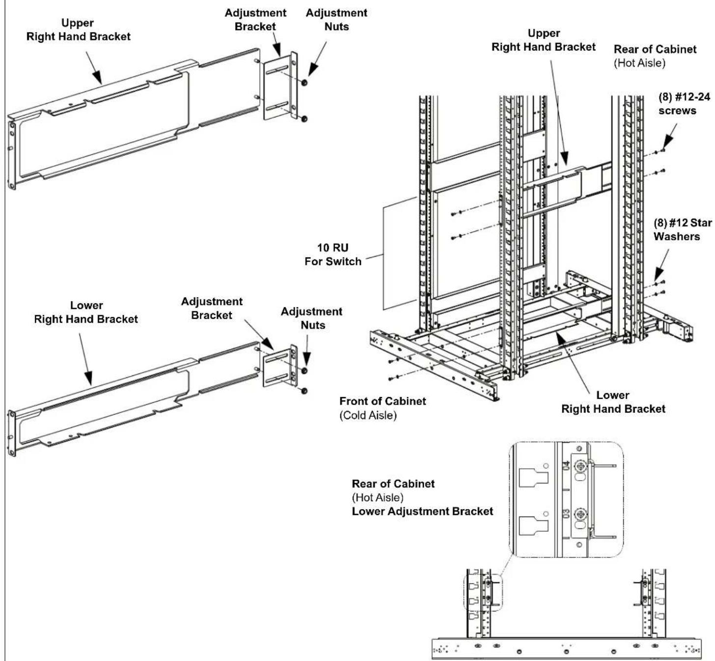
Upper / Lower Right Hand Bracket Installation
- The inlet duct system is designed to accommodate e-rail spacing between 23.6" to 25.4". A 4 post Cisco Nexus 7018 type rack mounting kit can be used as an alternative to the 6807 mounting kit.
• Measure distance between front and rear rails. - Loosen nuts on adjustment bracket and adjust to fit rail spacing.
• Install (1) Upper Right Hand Bracket with (4) #12-24 screws and (4) #12 star washers. (Leave screws loose until Inlet Box is installed.)
• Install (1) Lower Right Hand Bracket with (4) #12-24 screws and (4) #12 star washers. (Leave screws loose until Inlet Box is installed.)
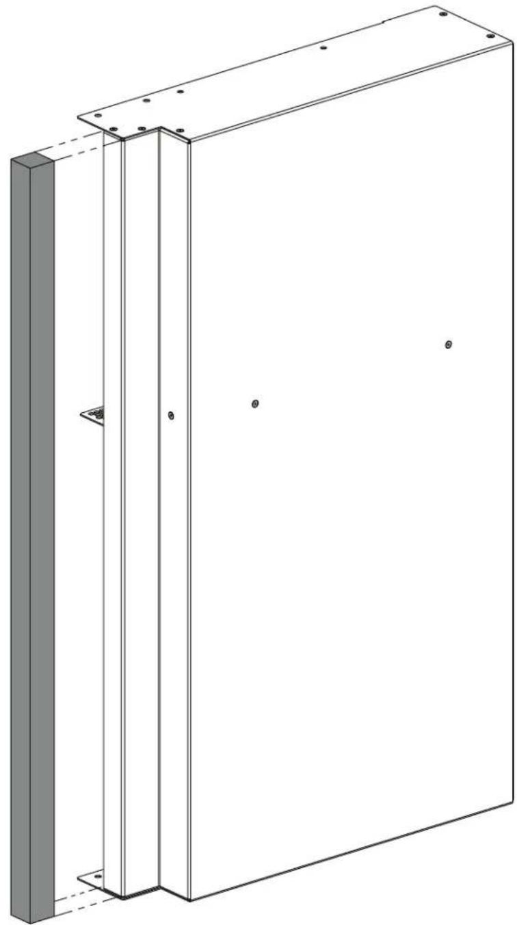
Attaching Foam Seal to Side Duct. (For Net-Access N-Type Only)
- Attach one strip of foam seal to flange on the front of side duct.
natural_image
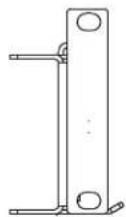
Technical line drawing of a rectangular panel with mounting holes and a vertical support (no text or symbols)Side Duct Installation
• Install Side Duct with (4) #10-32 nuts.
DAY 1: Without Side Panel
DAY 2: With Side Panel
Note: Side Duct can also be installed with Side Panel on.
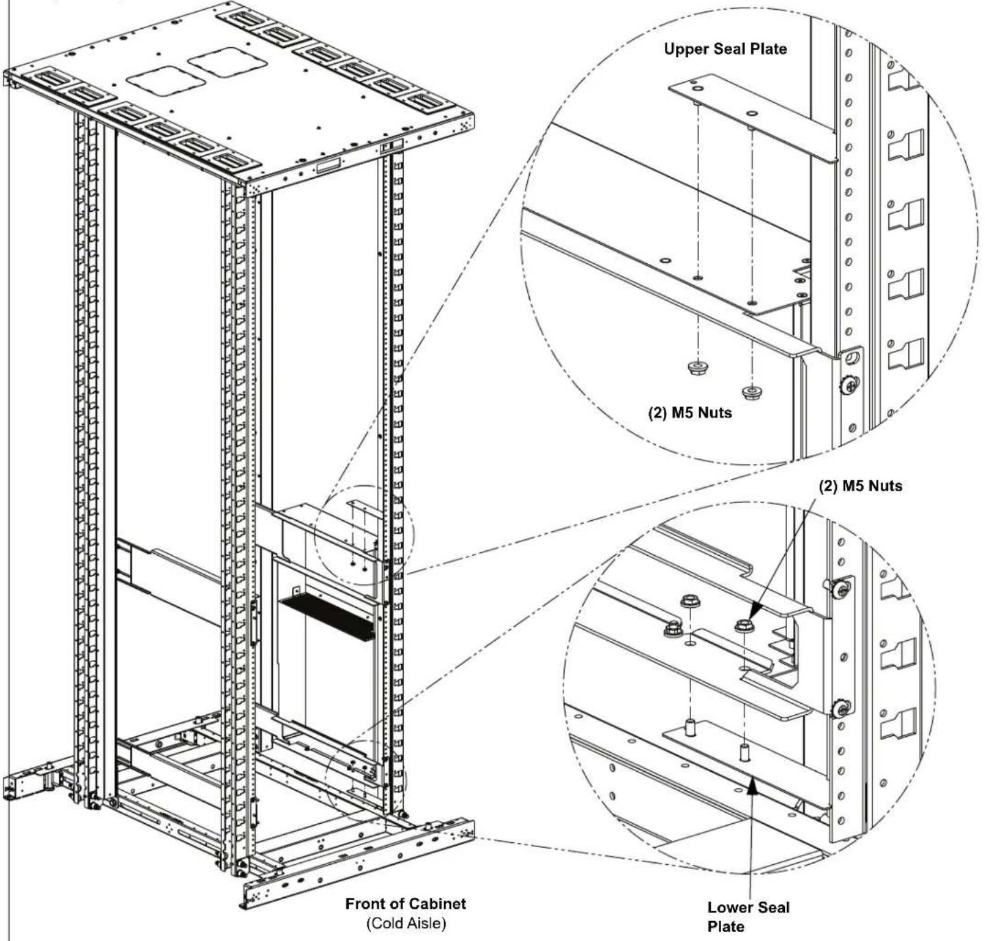
Upper / Lower Seal Plate Installation
- Slide studs on top seal plate into holes in the side duct.
- Secure top seal plate in place with (2) M5 nuts.
- Repeat process for bottom seal plate.
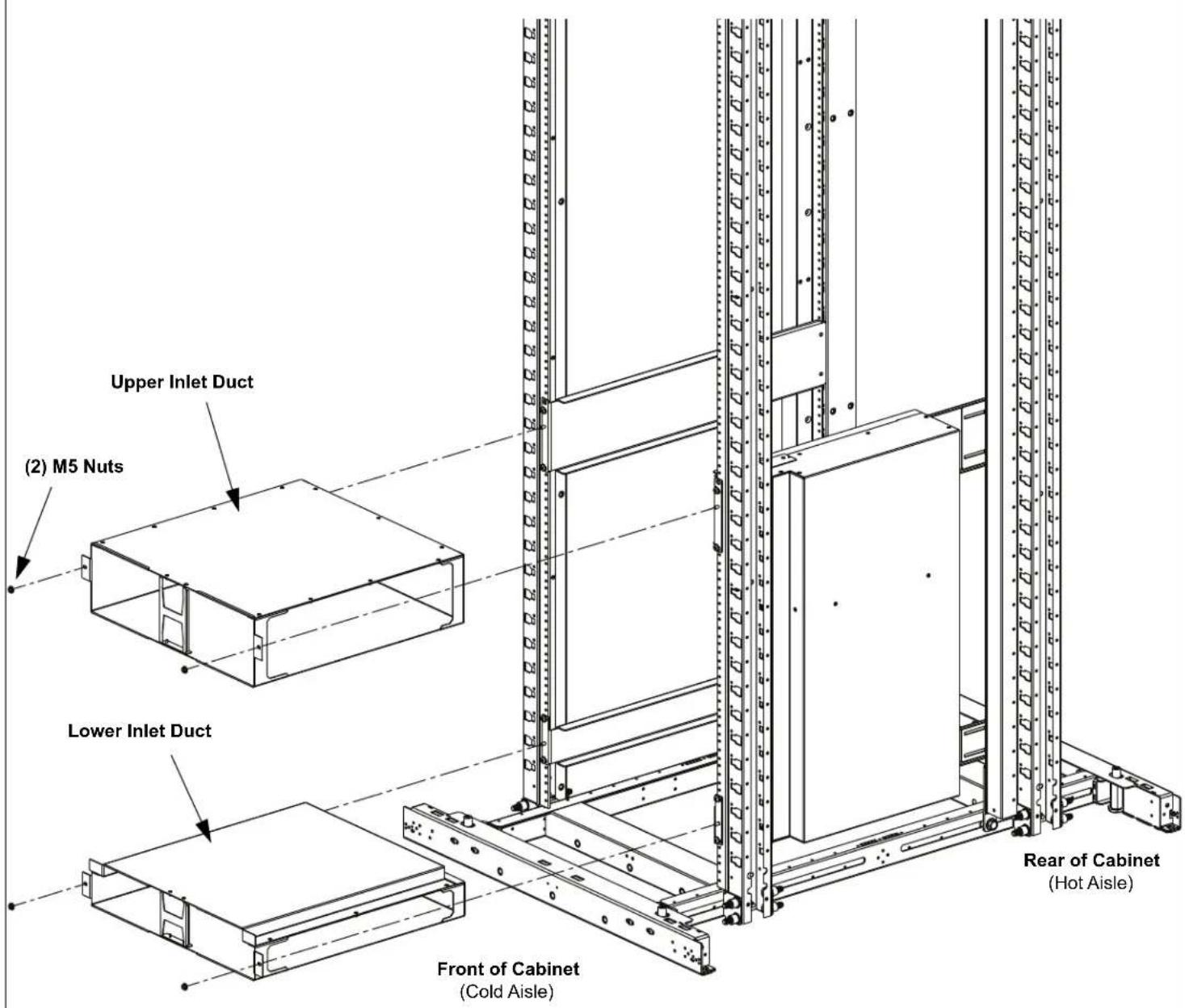
Rear of Cabinet
(Hot Aisle)
Upper / Lower Duct Box Installation
• Install (1) Upper Duct Box by sliding box into mounting rails and securing with (2) M5 nuts.
• Install (1) Lower Duct Box by sliding box into mounting rails and securing with (2) M5 nuts.
- Tighten all bracket screws.
For Instructions in Local Languages
and Technical Support:
www.panduit.com/resources/install_maintain.asp
PANDUIT
www.panduit.com
E-mail:
- INDEX
- PAGE
- Tools Needed:
- Hardware Supplied:
- Star Washer
- 12-24
- Device Placement
- • NOTES:
- Device Placement for Net-Access N-Type Cabinets (N\*\*\* )
- Upper / Lower Left Hand Bracket Installation
- Upper / Lower Right Hand Bracket Installation
- Attaching Foam Seal to Side Duct. (For Net-Access N-Type Only)
- Side Duct Installation
- Upper / Lower Seal Plate Installation
- Upper / Lower Duct Box Installation
Brand : Panduit
Model : DIRLC3210S17W
Category : Air Conditioning