
F70-4K8 - Video projector Barco - Free user manual and instructions
Find the device manual for free F70-4K8 Barco in PDF.


| Product Type | Video Projector |
| Display Technology | DLP (3-chip) |
| Resolution | 4K UHD (3840 x 2160) / WQXGA (2560 x 1600) |
| Brightness | Up to 8,000 ANSI lumens |
| Light Source | Laser phosphor |
| Lens Mount | Interchangeable bayonet mount (FLD+ series) |
| Lens Features | Motorized zoom, focus, shift; automatic lens detection |
| Connectivity | 2x DVI-D, 1x HDMI 2.0, 2x DisplayPort 1.2, 2x 3G-SDI, 1x HDBaseT, RS-232, LAN, DMX, USB, Trigger, Sync |
| Image Processing | Warping (4-corner, bow), blending, black level adjustment, CLO |
| 3D Support | Active 3D, frame packing, side-by-side, top-bottom |
| HDR Support | Perceptual Quantizer (PQ) |
| Color Enhancement | BrilliantColor, P7 RealColor |
| Control Interfaces | On-screen display, LCD touch panel, IR remote, RS-232, LAN, DMX |
| Power Requirements | 100-240 VAC, 50/60 Hz |
| Power Consumption | Typical 800-1200 W (depending on mode) |
| Dimensions (W x D x H) | 465 x 478 x 192 mm (without lens) |
| Weight | Approx 22 kg (without lens) |
| Safety Classification | Class 1 laser product, RG2 standard (RG3 with certain lenses) |
| Operating Temperature | 0 to 40 °C |
| Firmware Upgrade | Via USB or network |
| Optional Accessories | Flight case, rigging frame, various lenses (FLD/FLD+) |
Frequently Asked Questions - F70-4K8 Barco
User questions about F70-4K8 Barco
0 question about this device. Answer the ones you know or ask your own.
Ask a new question about this device
Download the instructions for your Video projector in PDF format for free! Find your manual F70-4K8 - Barco and take your electronic device back in hand. On this page are published all the documents necessary for the use of your device. F70-4K8 by Barco.
USER MANUAL F70-4K8 Barco
natural_image
Black projector with circular lens and control buttons (no visible text or symbols)User Manual
Barco NV
Beneluxpark 21, 8500 Kortrijk, Belgium
www.barco.com/en/support
www.barco.com
Registered office: Barco NV
President Kennedypark 35, 8500 Kortrijk, Belgium
www.barco.com/en/support
www.barco.com
Changes
Barco provides this manual 'as is' without warranty of any kind, either expressed or implied, including but not limited to the implied warranties or merchantability and fitness for a particular purpose. Barco may make improvements and/or changes to the product(s) and/or the program(s) described in this publication at any time without notice.
This publication could contain technical inaccuracies or typographical errors. Changes are periodically made to the information in this publication; these changes are incorporated in new editions of this publication.
The latest edition of Barco manuals can be downloaded from the Barco web site www.barco.com or from the secured Barco web site https://www.barco.com/en/signin.
Trademarks
Brand and product names mentioned in this manual may be trademarks, registered trademarks or copyrights of their respective holders. All brand and product names mentioned in this manual serve as comments or examples and are not to be understood as advertising for the products or their manufacturers.
Patent protection
Please refer to www.barco.com/about-barco/legal/patents.
Guarantee and Compensation
Barco provides a guarantee relating to perfect manufacturing as part of the legally stipulated terms of guarantee. On receipt, the purchaser must immediately inspect all delivered goods for damage incurred during transport, as well as for material and manufacturing faults Barco must be informed immediately in writing of any complaints.
The period of guarantee begins on the date of transfer of risks, in the case of special systems and software or the date of commissioning, at latest 30 days after the transfer of risks. In the event of justified notice of complaint, Barco can repair the fault or provide a replacement at its own discretion within an appropriate period. If this measure proves to be impossible or unsuccessful, the purchaser can demand a reduction in the purchase price or cancellation of the contract. All other claims, in particular those relating to compensation for direct or indirect damage, and also damage attributed to the operation of software as well as to other services provided by Barco, being a component of the system or independent service, will be deemed invalid provided the damage is not proven to be attributed to the absence of properties guaranteed in writing or due to the intent or gross negligence or part of Barco.
If the purchaser or a third party carries out modifications or repairs on goods delivered by Barco, or if the goods are handled incorrectly, in particular if the systems are operated incorrectly or if, after the transfer of risks, the goods are subject to influences not agreed upon in the contract, all guarantee claims of the purchaser will be rendered invalid. Not included in the guarantee coverage are system failures which are attributed to programs or special electronic circuitry provided by the purchaser, e.g. interfaces. Normal wear as well as normal maintenance are not subject to the guarantee provided by Barco either.
The environmental conditions as well as the servicing and maintenance regulations specified in this manual must be complied with by the customer.
Copyright ©
All rights reserved. No part of this document may be copied, reproduced or translated. It shall not otherwise be recorded, transmitted or stored in a retrieval system without the prior written consent of Barco.
Software License Agreement
You should carefully read the following terms and conditions before using this software. Your use of this software indicates your acceptance of this license agreement and warranty.
Terms and Conditions:
- No redistribution of the software is allowed.
- Reverse-Engineering. You may not reverse engineer, decompile, disassemble or alter this software product.
Disclaimer of Warranty:
This software and the accompanying files are sold “as is” and without warranties as to performance or merchantability or any other warranties whether expressed or implied. In no event shall Barco be liable for damage of any kind, loss of data, loss of profits, business interruption or other pecuniary loss arising directly or indirectly. Any liability of the seller will be exclusively limited to replacement of the product or refund of purchase price.
Patent protection
Please refer to www.barco.com/about-barco/legal/patents.
Disclaimer on GUI images used in this manual
The GUI images in this manual are example illustrations and should be treated as such. While the name of the projector displayed in the illustrations may be different from the projector model you are currently using, the menu lay-out and functionality is identical.
Table of contents
1 Safety 11
1.1 General considerations 12
1.2 Important safety instructions....13
1.3 Projector Hazard Distances 16
1.4 High Brightness Precautions....16
1.5 Hazard Distance for fully closed projection system 19
1.6 HD in function of the lens Throw Ratio (TR) 20
1.7 Safety symbols....21
2 Getting to know the projector. 23
2.1 Main Components 24
2.2 Service and Maintenance....25
2.3 LED Status Light 25
2.4 Power on / Standby button backlight indications....25
2.5 LCD Panel 26
2.5.1 LCD panel general 26
2.5.2 LCD touch panel 26
2.5.3 LCD Status screens 26
2.5.4 Dashboard page symbols 29
2.5.5 OSD Menu mode....29
2.5.6 LCD functionality in Ready Mode 29
2.6 Local keypad 29
2.7 Shortcut buttons....30
2.8 Basic remote control unit 31
2.9 Platinum remote control unit 32
2.9.1 Remote control, battery installation 32
2.9.2 Remote control, protocol setup 33
2.9.3 Functionality overview 35
2.9.4 Pulse RCU, function of the on/off button 35
2.9.5 Pulse RCU, function of the "RGB filter" button 36
2.9.6 Enable / Disable Remote Control 36
2.9.7 Wired RC connection....37
2.10 Projector Address 37
2.10.1 Controlling the projector 37
2.11 Connector panel 38
2.12 Color Wheels....39
2.13 Color Wheel Type 39
2.14 Optional Accessories 39
3 Lenses, Handling and features 41
3.1 Approved Lenses 42
3.2 Lens range 42
3.3 Replace a lens 45
3.4 Lens calibration....47
3.5 Installing the lens safety cable....48
3.6 Preparing the FLDX lens (0.38:1) UST 51
3.7 Mounting the FLDX lens (0.38:1) UST lens with a lens support....55
3.8 Mounting a safety cable to the FLDX lens (0.38:1) UST lens 58
4 Physical Installation....61
4.1 Installation process 62
4.2 Installation conditions....62
4.3 Initial inspection 63
4.4 Positioning the projector 64
4.5 Mounting the projector, general considerations....64
4.6 Projector safe attachment points 66
4.7 Throw distance 67
4.8 Scheimpflug (Boresight) introduction 69
4.9 Scheimpflug adjustment procedure....70
5 Getting started 73
5.1 Projector source and control connections....74
5.1.1 Making connections....74
5.1.2 Connector specifications....74
5.1.2.1 Specifications DVI-I inputs....74
5.1.2.2 Display Port 1.2....74
5.1.2.3 Specifications HDMI 2.0....75
5.1.2.4 Specifications SDI inputs....75
5.1.2.5 Specifications HDBase T input 75
5.1.3 Control interface specifications 76
5.1.3.1 RS-232 76
5.1.3.2 LAN/Ethernet 77
5.1.3.3 USB-A port....77
5.1.3.4 DMX 77
5.2 Power up the projector....77
5.3 Power down the projector 78
5.4 Power mode transitions....78
5.4.1 General 78
5.4.2 Power on projector 79
5.4.3 Going from READY to ON....79
5.4.4 Going from ON to READY....79
5.4.5 Going from READY to ECO standby....79
5.4.6 Going from ECO to ON 79
5.4.7 Wake On LAN (WOL) 79
5.5 Power modes 80
5.6 Customize projector settings 80
5.7 User interface 80
5.7.1 On Screen Display (OSD) 80
6 Source menu 83
6.1 Connector selection....84
6.2 Connector settings 84
6.3 Using dual inputs....86
7 Image menu 89
7.1 Contrast....91
7.2 Brightness....91
7.3 Saturation....92
7.4 Sharpness....92
7.5 Gamma adjustment 93
7.6 Gamma Types 94
7.6.1 Predefined Gamma types 94
7.6.2 DICOM Gamma 94
7.7 Digital Zoom Shift....95
7.7.1 Digital Zoom 96
7.7.2 Digital Shift....96
7.8 Advanced image adjustments 97
7.8.1 P7 Realcolor 97
7.8.2 Edit the RealColor presets....99
7.8.3 Output resolution 4K....100
7.8.4 Smear reduction 101
7.8.5 Brilliantcolor....101
7.8.6 Displaying HDR content– Perceptual Quantizer (PQ) 104
7.8.7 HDR Status....105
7.8.8 Night vision 105
8 Installation menu 107
8.1 Lens 108
8.1.1 Zoom / Focus.... 108
8.1.2 Shift 108
8.1.3 Shift to center 109
8.1.4 Iris 110
8.2 Orientation 111
8.3 Scaling modes....112
8.4 Warping 114
8.4.1 About warping....114
8.4.2 Warping – On/Off 115
8.4.3 Warping – Screen size 116
8.4.4 Warp - 4 Corners adjustment .....117
8.4.5 Warping-Bow 119
8.4.6 Warping – Warp files 122
8.4.7 Warping – Latency control in a multi projector setup 123
8.5 Blending 125
8.5.1 Introduction to blend functions.... 125
8.5.2 Set up the system 126
8.5.3 Blend mask setup procedure....126
8.5.4 Basic blend setup procedure....127
8.5.5 Black level setup procedure 128
8.5.6 Color level adjustment procedure....129
8.5.7 Black level files 130
8.5.8 Blend files 131
8.5.9 Advanced blend 132
8.6 CLO feature....132
8.6.1 Introduction....132
8.6.2 Placement of the light sensor 132
8.6.3 Using the CLO features....133
8.6.3.1 CLO feature in the OSD, Prospector and API......
8.6.3.2 Notifications applicable for the CLO feature 133
8.6.3.3 Example for using the CLO feature for maintaining brightness over time....134
8.6.4 CLO scale....134
8.6.4.1 CLO scale....134
8.6.4.2 Example: CLO scale with one projector 135
8.6.4.3 Example: CLO scale with 3 projectors....135
8.6.5 CLO stable signal....135
8.6.6 EWMA 136
8.6.7 Setpoint....136
8.6.8 CLO (Light sensor) calibration 136
8.7 IR / Night vision functionality.... 136
8.8 IG pixel shift....137
8.8.1 IG pixel shift.... 137
8.8.2 IG Pixelshift Night Vision....139
8.8.3 AutoStereo (3D) Setup 140
9 GUI – Profiles 141
9.1 Profiles introduction....142
9.2 Profiles setup parameters....142
9.3 Saving settings to a new profile 143
9.4 Deleting a projector profile....145
10 System settings menu 147
10.1 Communication....148
10.2 Remote control....148
10.2.1 Broadcast address 148
10.2.2 Projector address.... 149
10.2.3 IR sensors 150
10.3 Host name - custom projector name setup.... 151
10.4 DMX....151
10.5 Trigger 153
10.6 Language....153
10.7 Themes....154
10.8 Units 154
10.9 Backlight 155
10.10 ECO mode 155
10.11 Power settings 156
10.12 Lens features.... 156
10.13 24/7 Mode 157
10.14 Maintenance 157
10.15 Lens calibration....158
10.16 Reset....159
10.17 Controlling the backlight of the LCD Display 161
11 GUI – Status menu.... 163
11.1 Status menu overview 164
3D 167
12.1 Setup 3D mode....168
13 Upgrade projector firmware 171
13.1 Upgrade procedure.... 172
14 User maintenance — Cleaning the projector 173
14.1 Projector lenses 174
14.2 Projector cabinet 174
14.3 Filters 174
15 Technical Specifications.... 175
15.1 F70 4k6....176
15.2 F70 W6 177
15.3 FS70 4k6....179
15.4 FS70 W6 180
A Color component mapping 183
A.1 Introduction....184
A.2 How infrared is displayed 184
A.3 Default setup 184
A.4 Cloned image with full RGB input 185
A.5 Cloned inputs with only green content for IR.... 186
B Image settings and adjustments for optimal latency 187
B.1 Introduction....188
B.2 Latency 188
B.3 DMD display device....188
B.4 Image display 188
B.5 Image positioning....190
C DMX Chart 191
C.1 DMX chart, Basic 192
C.2 DMX chart, Extended 193
D Overview video timings for video interfaces 195
D.1 Overview video timings.... 196
D.2 Overview video timings SDI Inputs 197
D.3 Overview video timings HDMI 2.0 inputs....198
D.4 Overview video timings DisplayPort 1.2 inputs....200
D.5 Overview video timings HDBaseT input....201
D.6 Overview video timings DVI Inputs 203
E Regulatory information 205
E.1 Product compliance 206
E.2 Turkey RoHS compliance 206
E.3 China RoHS compliance....207
E.4 Taiwan RoHS compliance 208
E.5 Contact information....209
E.6 Production address....209
E.7 Product Info 210
E.8 Disposal Information 210
E.9 Disposal of batteries....210
Index 211
Safety
1
1.1 General considerations 12
1.2 Important safety instructions.... 13
1.3 Projector Hazard Distances.... 16
1.4 High Brightness Precautions 16
1.5 Hazard Distance for fully closed projection system 19
1.6 HD in function of the lens Throw Ratio (TR) 20
1.7 Safety symbols....21
About this chapter
Read this chapter thoroughly before attempting to install or operate the projector.
To prevent personal injury to users or physical damage to the projector while installing and using your projector, ensure that you understand and follow all safety guidelines, instructions and warnings included in this chapter and this manual.
Clarification of the term F70 / F90 series used in this document
Use in this document of the term, F70 / F90 series, means that the content is applicable for the following products:
F90-W13WUXGA
• F90-4K13 4KUHD/WQXGA
F70 — 4K6
F70 — W6
Defining the GP6 platform
The F90 series products in general, are all products within the Barco GP6 Platform.
Defining the GP7 platform
The F70 series products in general, are all products within the Barco GP7 Platform
1.1 General considerations
Notice on optical radiation F90 Series
- The projector is Class 1 laser product that conforms with IEC EN 60825-1:2014. The projector conforms with IEC 60825-1:2007, and with performance standards for laser products under 21 CFR 1040, except with respect to those characteristics authorized by Variance Number 2016-V-0144 effective December 12, 2019 Do not stare into Beam.
- This projector is Risk Group 2 (RG2) according to IEC EN 62471-5.
This projector may become Risk Group 3 (RG3) when an interchangeable lens with throw ratio greater than 3.15 is installed.
Refer to the manual for the lens list and throw ratio before operation.
Such combination of projector and lens are intended for professional use only, and are not intended for consumer use.
- For RG3, no direct exposure to the beam shall be permitted.
For RG3, operators shall control access to the beam within the hazard distance or install the product at a height that will prevent eye exposure within the hazard distance. - This projector has two (2) built-in Class 4 laser clusters. Disassembly or modification is very dangerous and should never be attempted.
- Any operation or adjustment not specifically instructed by the user's guide creates the risk of hazardous laser radiation exposure.
- Do not open or disassemble the projector as this may cause damage by the exposure of laser radiation.
Notice on optical radiation F70 Series
- The projector is Class 1 laser product that conforms with IEC EN 60825-1:2014. The projector conforms with IEC 60825-1:2007, and with performance standards for laser products under 21 CFR 1040, except with respect to those characteristics authorized by Variance Number 2016-V-0144 effective December 12, 2019 Do not stare into Beam.
- This projector is Risk Group 2 (RG2) according to IEC EN 62471-5.
This projector may become Risk Group 3 (RG3) when an interchangeable lens with throw ratio greater than 4.7 is installed.
Refer to the manual for the lens list and throw ratio before operation.
Such combination of projector and lens are intended for professional use only, and are not intended for consumer use.
- For RG3, no direct exposure to the beam shall be permitted.
For RG3, operators shall control access to the beam within the hazard distance or install the product at a height that will prevent eye exposure within the hazard distance. - This projector has one (1) built-in Class 4 laser clusters. Disassembly or modification is very dangerous and should never be attempted.
- Any operation or adjustment not specifically instructed by the user's guide creates the risk of hazardous laser radiation exposure.
- Do not open or disassemble the projector as this may cause damage by the exposure of laser radiation.
General safety instructions
- This product contains no user serviceable parts except the Color Wheel in F90 projectors.
When projector becomes RG3, change of color wheel must only be performed by authorized service personnel.
Attempts to modify/replace mechanics or electronics inside the housing or compartments will violate any warranties and may be hazardous.
Do not remove/replace any other parts than the Color Wheel. Other parts, service personnel only – Warranty void if Removed. Follow the instructions in the User Guide to replace the Color Wheel.
- Do not stare into beam when the projector is on. The bright light may result in permanent eye damage.
- Not following the prescribed control, adjustment or operation procedure may cause damage by the exposure of laser radiation.
-
Before operating this equipment please read this manual thoroughly and retain it for future reference.
• Installation and preliminary adjustments should be performed by properly trained and qualified personnel. -
All warnings on the projector and in the documentation manuals must be adhered to.
- All instructions for operating and use of this equipment must be followed precisely.
- All local installation codes should be adhered to.
Notice on safety
This equipment is built in accordance with the requirements of the international safety standards IEC60950-1, as basis for National safety regulation world wide. The safety standard covers information technology equipment including electrical business equipment intended to operate in “normal” environments (offices and homes). This safety standard imposes important requirements on the use of safety critical components, materials and insulation, in order to protect the user or operator against risk of electric shock and energy hazard and having access to live parts. Safety standards also impose limits to the internal and external temperature rises, radiation levels, mechanical stability and strength, enclosure construction and protection against the risk of fire. Simulated single fault condition testing reduce the risk of hazards and contribute to ensure the safety of the equipment to the user even when the equipment’s normal operation fails.
Users definition
Throughout this manual, the term SERVICE PERSONNEL refers to Barco authorized persons having appropriate technical training and experience necessary to be knowledgeable of potential hazards to which they are exposed (including, but not limited to HIGH VOLTAGE ELECTRIC and ELECTRONIC CIRCUITRY and HIGH BRIGHTNESS PROJECTORS) in performing a task, and of measures to minimize the potential risk to themselves or other persons. Only Barco authorized SERVICE PERSONNEL, knowledgeable of such risks, are allowed to perform service functions inside the product enclosure. The term USER and OPERATOR refers to any person other than SERVICE PERSONNEL.
When installing an interchangeable lens with a throw ratio that makes the projector become an RG3 unit, (See chapter "Approved lenses" in the User manual), refer to chapter "High Brightness Precautions", page 16 for information regarding precautions.
Refer to the user manual for the lens list and hazard distance before operation. Such combination of projector and lens are intended for professional use only, and are not intended for consumer use.
FOR PROFESSIONAL USE ONLY means installation can only be carried out by Barco AUTHORIZED PERSONNEL familiar with potential hazards associated with high intensity light beams.
1.2 Important safety instructions
To prevent the risk of electrical shock
- This product should be operated from a mono phase AC power source.
- This apparatus must be grounded (earthed) via the supplied 3 conductor AC power cable. If none of the supplied power cables are the correct one, consult your dealer.
If you are unable to insert the plug into the outlet, contact your electrician to replace your obsolete outlet. Do not defeat the purpose of the grounding-type plug.
Never use 2-prong power cords, as this is dangerous and could lead to electrical shock.
- Do not allow anything to rest on the power cord. Do not locate this product where persons will walk on the cord. To disconnect the cord, pull it out by the plug. Never pull the cord itself.
- Use only the power cord supplied with your device or original replacement cords. While appearing to be similar, other power cords have not been safety tested at the factory and may not be used to power the device. For a replacement power cord, contact your dealer.
- Do not operate the projector with a damaged cord. Replace the cord.
Do not operate the projector if the projector has been dropped or damaged - until it has been examined and approved for operation by a qualified service technician.
- Position the cord so that it will not be tripped over, pulled, or contact hot surfaces.
- If an extension cord is necessary, a cord with a current rating at least equal to that of the projector should be used. A cord rated for less amperage than the projector may overheat.
- Never push objects of any kind into this product through cabinet slots as they may touch dangerous voltage points or short out parts that could result in a risk of fire or electrical shock.
- Make sure that no objects enter into the vents and openings of the set.
- Do not expose this projector to rain or moisture.
- The projector is designed for indoor use only. Never operate the unit outdoors.
- Do not immerse or expose this projector in water or other liquids.
- Do not spill liquid of any kind on this projector.
- Should any liquid or solid object fall into the cabinet, unplug the set and have it checked by qualified service personnel before resuming operations.
- Do not disassemble this projector, always take it to an authorized trained service person when service or repair work is required.
- Do not use an accessory attachment which is not recommended by the manufacturer.
- Lightning - For added protection for this video product during a lightning storm, or when it is left unattended and unused for long periods of time, unplug it from the wall outlet. This will prevent damage to the device due to lightning and AC power-line surges.
To prevent personal injury
- To prevent injury and physical damage, always read this manual and all labels on the system before connecting to the wall outlet or adjusting the projector.
• To prevent injury, take note of the weight of the projector. - To prevent injury, ensure that the lens and all covers are correctly installed. See installation procedures.
- Warning: high intensity light beam. NEVER look into the lens! High luminance could result in damage to the eye.
- Warning: extremely high brightness laser: This projector uses extremely high brightness laser. Never attempt to look directly into the lens or at the laser.
- Always switch off the projector and disconnect from the mains power supply before attempting to remove any of the projector covers or access parts inside the projector.
- This product contains no user serviceable parts except the Color Wheel. Attempts to modify/replace mechanics or electronics inside the housing or compartments will violate any warranties and may be hazardous.
- Do not remove/replace any other parts than the Color Wheel. Other parts, service personnel only Warranty void if removed
- Do not place this equipment on an unstable cart, stand, or table. The product may fall, causing serious damage to it and possible injury to the user.
- Only place the projector on a stable surface, or mount it securely using an approved ceiling-mount.
- It is hazardous to operate without lens or lens cap. Lenses or shields shall be changed if they have become visibly damaged, for example with cracks or deep scratches, to such an extent that their effectiveness is impaired.
To prevent fire hazard
- Barco projection products are designed and manufactured to meet the most stringent safety regulations. This projector radiates heat on its external surfaces and from ventilation ducts during normal operation, which is both normal and safe. Exposing flammable or combustible materials into close proximity of this projector could result in the spontaneous ignition of that material, resulting in a fire. For this reason, it is absolutely necessary to leave an “exclusion zone” around all external surfaces of the projector whereby no flammable or combustible materials are present. The exclusion zone in the exhaust area must be not less than 100 cm (40"). The exclusion zone on the intake area must not be less than 50 cm (20").
- Do not place flammable or combustible materials near the projector!
- For the F90 projector, the exclusion zone on the lens side within the light beam must be at least 1.5m.
- For the F70 projector the exclusion zone on the lens side within the light beam must be at least 1,0m.
- Caution! Hot air is exhausted from the rear vent. Do not place objects that are sensitive to heat nearer than 100 cm (40") to the exhaust vent.
- Slots and openings in this equipment are provided for ventilation. To ensure reliable operation of the projector and to protect it from overheating, these openings must not be blocked or covered.
- The openings should never be blocked by placing the projector too close to walls, or other similar surface. Allow for sufficient distance to walls and ceilings to avoid overheating. Minimum safety distance to the exhaust area of the unit must not be less than 100 cm (40") and to the intake area, not less than 50 cm (20").
- This projector should never be placed near or over a radiator or heat register.
- This projector should not be placed in a built-in installation or enclosure unless proper ventilation is provided.
- Do not cover the projector or the lens with any material while the projector is in operation. Keep flammable and combustible materials away from the projector at all times.
- Mount the projector in a well-ventilated area away from sources of ignition and out of direct sun light. Always allow ample airflow through the projector.
- Never expose the projector to rain or moisture. In the event of fire, use sand, CO2 or dry powder fire extinguishers.
- Never use water on an electrical fire.
- Always have service performed on this projector by authorized Barco service personnel. Always insist on genuine Barco replacement parts. Never use non-Barco replacement parts as they may degrade the safety of this projector.
- Projection rooms must be well ventilated or cooled in order to avoid heat buildup.
- Let the projector cool down completely before storing. Remove cord from the projector when storing.
To prevent projector damage
- To ensure correct airflow is maintained the projector should only be operated when all of its covers in place.
- Always remove lens cap before switching on the projector. If the lens cap is not removed, it may melt due to the high energy light emitted through the lens. Melting the lens cap may permanently damage the surface of the projection lens
- Only connect the projector to signal sources and voltages as described in the technical specification. Connecting to unspecified signal sources or voltages may lead to malfunction and permanent damage of the unit.
• To ensure correct airflow is maintained, it should only be operated when all of its covers are in place. - The projector must always be installed in a manner which ensures free flow of air into its air inlets and unimpeded evacuation of the hot air from its cooling system.
- Slots and openings in the cabinet are provided for ventilation. To ensure reliable operation of the product and to protect it from overheating, these openings must not be blocked or covered. The openings should never be blocked by placing the product on a bed, sofa, rug, or other similar surface. This product should never be placed near or over a radiator or heat register. The device should not be placed in a built-in installation or enclosure unless proper ventilation is provided. Ensure that nothing can be spilled on, or dropped inside the projector. If this does happen, switch off and unplug the mains supply immediately. Do not operate the projector again until it has been checked by Barco authorized service personnel.
- Do not block the projector cooling fans or free air movement around the projector. Minimum safety distance to the exhaust area of the unit must not be less than 100 cm (40") and to the intake area, not less than 50 cm (20").
- Do not use this equipment near water.
- Do not operate the projector outside its temperature and humidity specifications as this may result in overheating and malfunction.
- Never place the projector in direct sun light. Sun light on the lens can severely damage the Digital Mirror Devices™ in which case there is a loss of warranty.
- Save the original shipping carton and packing material. They will come in handy if you ever have to ship your equipment. For maximum protection, repack your set as it was originally packed at the factory.
- Unplug this product from the wall outlet before cleaning. Do not use liquid cleaners or aerosol cleaners. Use a damp cloth for cleaning. Never use strong solvents, such as thinner or benzine, or abrasive cleaners, since these will damage the cabinet. Stubborn stains may be removed with a cloth lightly dampened with mild detergent solution.
- To ensure the highest optical performance and resolution, the projection lenses are specially treated with an anti-reflective coating, therefore, avoid touching the lens. To remove dust on the lens, use a soft dry cloth. Do not use a damp cloth, detergent solution, or thinner.
On servicing
- Do not attempt to service this product yourself, as opening or removing covers may expose you to dangerous voltage potentials and risk of electric shock.
• Refer all servicing to qualified service personnel. - Attempts to alter the factory-set internal controls or to change other control settings not specially discussed in this manual can lead to permanent damage to the projector and cancellation of the warranty.
- Replacement parts: When replacement parts are required, be sure the service technician has used original Barco replacement parts or authorized replacement parts which have the same characteristics as the Barco original part. Unauthorized substitutions may result in degraded performance and reliability, fire, electric shock or other hazards. Unauthorized substitutions may void warranty.
- Safety check: Upon completion of any service or repairs to this projector, ask the service technician to perform safety checks to determine that the product is in proper operating condition.
Malfunction unit
Remove all power from the projector and refer servicing to qualified service technicians under the following conditions:
- When the power cord or plug is damaged or frayed.
- If liquid has been spilled into the equipment.
- If the product has been exposed to rain or water.
- If the product does not operate normally when the operating instructions are followed. Adjust only those controls that are covered by the operating instructions since improper adjustment of the other controls may result in damage and will often require extensive work by a qualified technician to restore the product to normal operation.
- If the product has been dropped or the cabinet has been damaged.
- If the product exhibits a distinct change in performance, indicating a need for service.
1.3 Projector Hazard Distances
For F90 series: WARNING. This may be a RG3 laser Product, dependent on which lens used.
This projector may become Risk Group 3 (RG3) when an interchangeable lens with throw ratio greater than 3.15 is installed.
Refer to the product manual for the lens list and throw ratio before operation.
Do not look directly in to the beam from the projector lens.
No direct eye exposure to the beam is permitted.
Operators shall control access to the beam within the hazard distance or install the product at a height that will prevent eye exposure within the hazard distance.
See table below for a definition of hazardous distances versus the throw ratio of the lens.
For F70 Series: WARNING. This may be a RG3 laser Product, dependent on which lens used.
This projector may become Risk Group 3 (RG3) when an interchangeable lens with throw ratio greater than 4.7 is installed.
Refer to the product manual for the lens list and throw ratio before operation.
Do not look directly in to the beam from the projector lens.
No direct eye exposure to the beam is permitted.
Operators shall control access to the beam within the hazard distance or install the product at a height that will prevent eye exposure within the hazard distance.
See table below for a definition of hazardous distances versus the throw ratio of the lens.
1.4 High Brightness Precautions
Restriction Zone (RZ) based on the HD (Hazard Distance).
The HD depends on the amount of lumens produced by the projector and the type of lens installed. See next chapter "HD in function of the lens Throw Ratio (TR)", page 8.
To protect untrained end users (as cinema visitors) the installation shall comply with the following installation requirements: Operators shall control access to the beam within the hazard distance or install the product at the height that will prevent spectators' eyes from being in the hazard distance. Radiation levels in excess of the limits will not be permitted at any point less than 2.0 meter (SH) above any surface upon which persons
other than operators, performers, or employees are permitted to stand or less than 1.0 meter (SH) lateral separation from any place where such persons are permitted to be. In non-cinema environments where unrestrained behavior is reasonably foreseeable, the minimum separation height should be greater than or equal to 3.0 meter to prevent potential exposure, for example by an individual sitting on another individual's shoulders, within the HD.
These values are minimum values and are based on the guidance provided in IEC 62471-5:2015 section 6.6.5.
The end user must understand the risk and apply protective measures based upon the hazard distance as indicated on the label and in the user information. Installation method, barriers, detection system or other applicable control measure shall prevent hazardous eye access to the radiation within the hazard distance.
For example, projectors that have a HD greater than 1 m and emit light into an uncontrolled area where persons may be present should be positioned in accordance with “the fixed projector installation” parameters, resulting in a HD that does not extend into the audience area unless the beam is at least 2.0 meter above the floor level. In non-cinema environments where unrestrained behavior is reasonably foreseeable, the minimum separation height should be greater than or equal to 3.0 meter to prevent potential exposure, for example by an individual sitting on another individual's shoulders, within the HD. For example, a sufficiently large separation height may be achieved by mounting the image projector on the ceiling or through the use of physical barriers.
For applications installed in the USA market the above limits for cinema like environments do not apply. The relevant minimum separation height is 2.5m (8,2 ft) by the FDA CDRH. Non cinema like environments require 2.5 meter (8.2 ft) separation height and 1.0 meter (3.3 ft) separation width for areas where restrained behavior is to be expected. All other areas require 3.0 (9.9 ft) separation height.
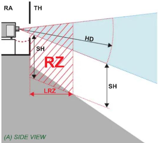
Image 1-1
A Side View
B Top View
RA Restricted Area
PR Projector
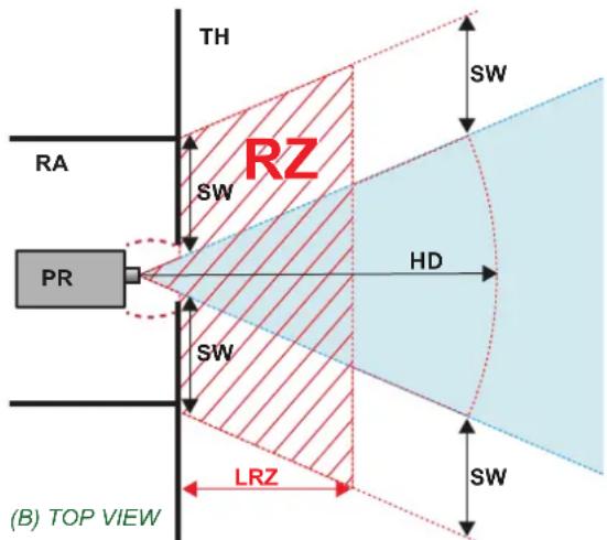
TH Theater
RZ Restriction Zone in the theater
SH Separation Height
SW Separation Width

Regarding the SH Distance: For Cinema applications, the distance must be >2m. For Concert applications, the distance must be >3m.
Based on national requirements, no person is allowed to enter the projected beam within the zone between the projection lens and the related hazard distance (HD). This shall be physically impossible by creating sufficient separation height or by placing barriers. The minimum separation height takes into account the surface upon which persons other than operator, performers or employees are permitted to stand.
On image 1-2 a typical setup is displayed. It must be verified if these minimum requirements are met. If required a restricted zone (RZ) in the theater must be established. This can be done by using physical barrier, like a red rope as illustrated in image 1-2.
The restricted area sticker can be replaced by a sticker with only the symbol.
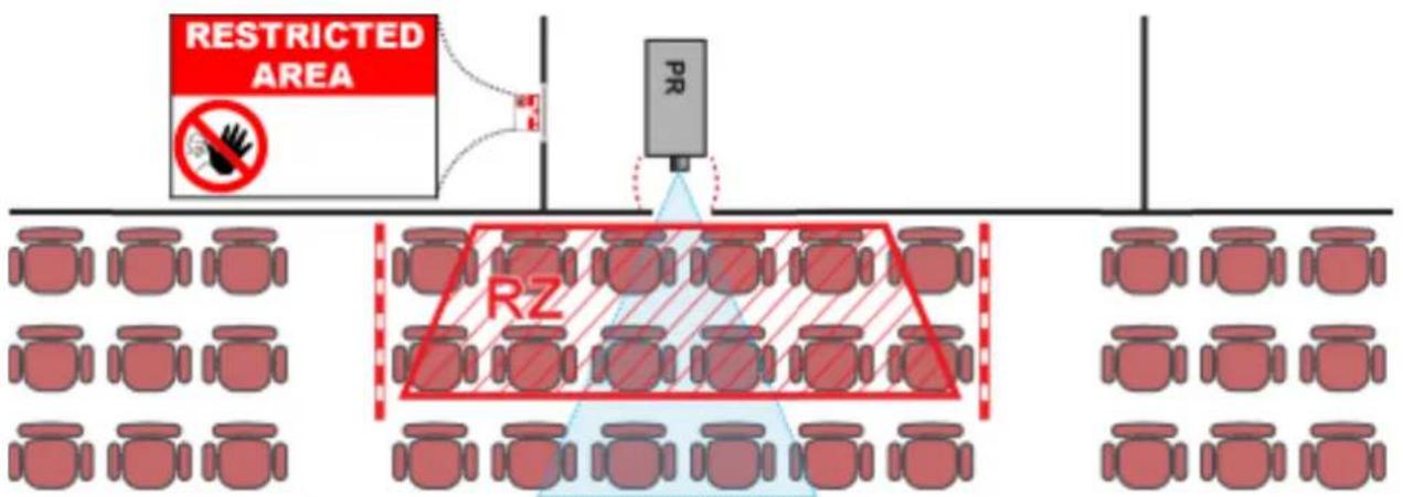
Image 1-2
USA market
For LIPs (Laser Illuminated Projectors) installed in the USA market other restriction zone conditions apply.
LIPs for installation in restrained environment (cinema theaters, business rooms, class rooms, museums ...) shall be installed at height vertically above the floor such that the bottom plane of the hazard distance zone shall be no lower than 2.5 meters above the floor. Horizontal clearance to the hazard distance zone shall be not less than 1 meter. Alternatively, in case the height of the separation barrier for the horizontal clearance is at least 1 meter high then the horizontal clearance (SW) can be reduced to:
- 0 meter if the height of the hazard zone is minimum 2.5 meter.
- 0.1 meter if the height of the hazard zone is minimum 2.4 meter.
- 0.6 meter if the height of the hazard zone is minimum 2.2 meter.
LIPs for installations in unrestrained environment (concerts, ...) shall be installed at a height vertically above the floor such that the bottom plane of the Hazard distance Zone shall be no lower than 3 meters above the floor. Horizontal clearance to the hazard distance zone shall be not less than 2.5 meters. Any human access horizontally to the Hazard Zone, if applicable, shall be restricted by barriers. If human access is possible in an unsupervised environment, the horizontal or vertical clearances shall be increased to prevent exposure to the hazard distance zone.
The LIP shall be installed by Barco or by a trained and Barco-authorized installer or shall only be transferred to laser light show variance holders. This is applicable for dealers and distributors since they may need to install the LIP (demo install) and/or they transfer (sell, rent, lease) the LIP. Dealers and distributors shall preserve sales and installation records for a period of 5 years. Variance holders may currently hold a variance for production of Class IIIB and IV laser light shows and/or for incorporating RG3 LIPs. Laser light show variance for RG3 LIPs can be requested by mailing the application to RadHealthCustomerService@fda.hhs.gov.
The installation checklist for laser illuminated RG3 projectors must be fully completed after the installation. The installation checklist can be downloaded from the Barco website. The installer shall preserve the checklist for a period of 5 years.
Install one or more readily accessible controls to immediately terminate LIP projection light. The power input at the projector side is considered as a reliable disconnect device. When required to switch off the projector, disconnect the power cord at the projector side. In case the power input at the projector side is not accessible (e.g. truss mount), the socket outlet supplying the projector shall be installed nearby the projector and be easily accessible, or a readily accessible general disconnect device shall be incorporated in the fixed wiring.
1.5 Hazard Distance for fully closed projection system

HD
Hazard Distance (HD) is the distance measured from the projection lens at which the intensity or the energy per surface unit becomes lower than the applicable exposure limit on the cornea or on the skin. The light beam is considered (to be) unsafe for exposure if the distance from a person to the light source is less than the HD.
Restriction Zone RZ Based on the HD
The projector is also suitable for rear projection applications; projecting a beam onto a defuse coated projection screen. As displayed in image 1-3 two areas should be considered: the restricted enclosed projection area (RA) and the observation area (TH).
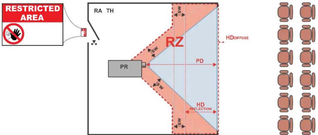
Image 1–3
RA Restricted Access location (Enclosed projection area)
PR Projector.
TH Theater (observation area).
RZ Restriction Zone
PD Projection Distan
SW Separation Width. Must be minimum 1 meter.
Restriction zone (RZ) based on the HD continued.
For this type of setup 3 different HD shall be considered:
- HD as discussed in "High Brightness precautions: Hazard Distance (HD)", page 6, relevant for intrabeam exposure.
- HDreflection: the distance that has to be kept restrictive related to the reflected light from the rear projection screen.
- HDdiffuse : the relevant distance to be considered while observing the defuse surface of the rear projection screen.
As described in "High Brightness precautions: Hazard Distance (HD)", page 6, it is mandatory to create a restricted zone within the beam areas closer than any NOHD. In the enclosed projection area the combination of two restricted zones are relevant: The restricted zone of the projected beam toward the screen; taking into account 1 meter Separation Width (SW) from the beam onward. Combined with the restricted zone related to the rear reflection from the screen (HDreflection); also taking into account a 1 meter lateral separation.
The HDreflection distance equals 25% of the difference between the determined HD distance and the projection distance to the rear projection screen. To determine the HD distance for the used lens and projector model see graphs in chapter "HD in function of the lens Throw Ratio (TR)", page 8.
HDreflection = 25% (HD - PD)
The light emitted from the screen within the observation shall never exceed the RG2 exposure limit, determined at 10 cm. The HDdiffuse can be neglected if the measured light at the screen surface is below 5000 cd/m² or 15000 LUX.
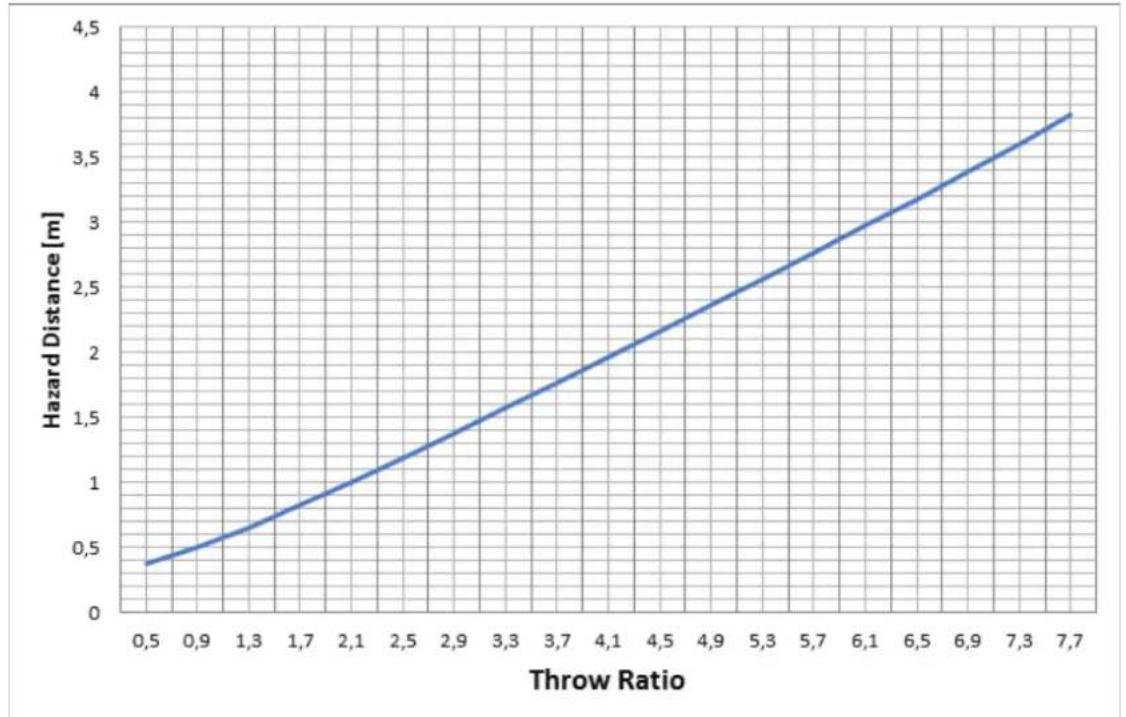
1.6 HD in function of the lens Throw Ratio (TR)

TR (Throw Ratio)
The ratio of the distance to the screen (throw) to the screen width.
HD versus Throw Ratio
line
| Throw Ratio | Hazard Distance [m] | | ----------- | ------------------- | | 0.5 | 0.4 | | 1.3 | 0.8 | | 2.1 | 1.2 | | 2.9 | 1.6 | | 3.7 | 2.0 | | 4.5 | 2.4 | | 5.3 | 2.8 | | 6.1 | 3.2 | | 6.9 | 3.6 | | 7.7 | 4.0 |Image 1-4 Hazard Distance in meters versus Throw ratio of the lens for the F90 projectors
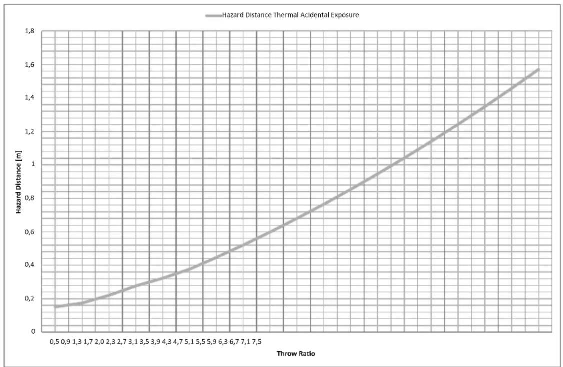
line
| Throw Ratio | Hazard Distance Thermal Acidental Exposure [m] | | ----------- | --------------------------------------------- | | 0.5 | 0.15 | | 0.9 | 0.18 | | 1.3 | 0.20 | | 1.7 | 0.23 | | 2.0 | 0.26 | | 2.3 | 0.29 | | 2.7 | 0.32 | | 3.1 | 0.35 | | 3.5 | 0.38 | | 3.9 | 0.41 | | 4.3 | 0.44 | | 4.7 | 0.47 | | 5.1 | 0.50 | | 5.5 | 0.53 | | 5.9 | 0.56 | | 6.3 | 0.59 | | 6.7 | 0.62 | | 7.1 | 0.65 | | 7.5 | 0.68 |Image 1-5 Hazard Distance in meters versus Throw ratio of the lens for the F70 projectors
Graphs shows Hazard Distance in meters versus Throw ratio of the lens
1.7 Safety symbols
Description of safety symbols used in product documentation or on product.
| Image Description | |
 | Refer to user manual for further information! |
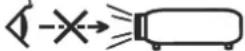 | Caution! Do not stare into beam, RG2 product. |
 | No telephone! Do not connect to telephone lines. |
For F90 series: Warning Label  | Caution! With Interchangeable lens with throw ratio greater then 3.15, consider hazard distance and installation requirements for RG3 product. Refer User manual. |
For F90 series: FDA Label 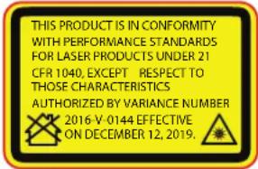 | |
| For F70 Series: Warning label Caution! With Interchangeable lens with throw ratio greater then 4.7, | |
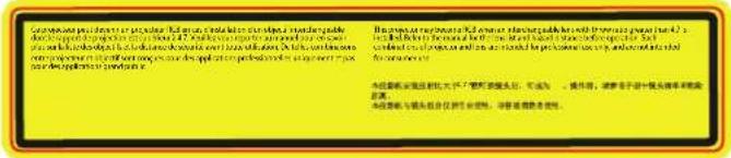 | consider hazard distance and installation requirements for RG3 product. Refer User manual. |
For F70 Series: FDA Label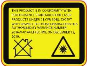 | |
F70 EMC Label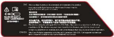 | |
F90 EMC Label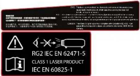 | |
Location of Safety Label
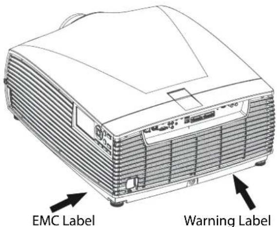
Image 1–6 F90 Projector
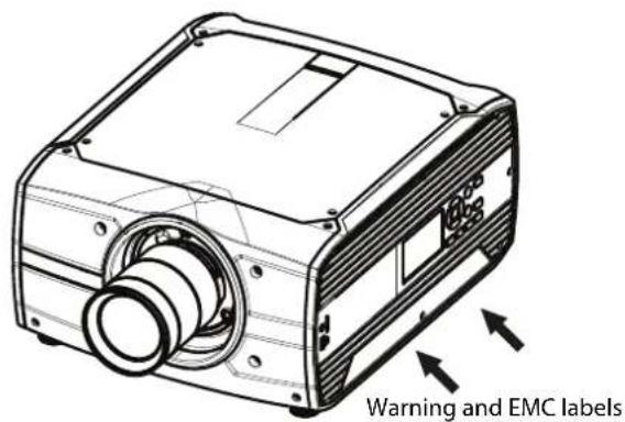
Image 1–7 F70 Projector

CAUTION: This product contains chemicals, including lead, known to the State of California to cause birth defects or other reproductive harm. Recycle properly, do not dispose of in ordinary waste!
Getting to know the projector.
2
2.1 Main Components 24
2.2 Service and Maintenance....25
2.3 LED Status Light 25
2.4 Power on / Standby button backlight indications....25
2.5 LCD Panel 26
2.6 Local keypad....29
2.7 Shortcut buttons 30
2.8 Basic remote control unit....31
2.9 Platinum remote control unit 32
2.10 Projector Address....37
2.11 Connector panel....38
2.12 Color Wheels 39
2.13 Color Wheel Type 39
2.14 Optional Accessories 39
2.1 Main Components
Naming Conventions
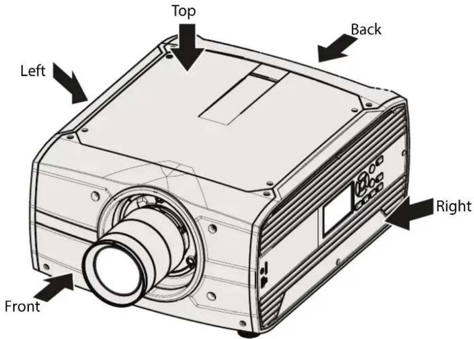
Image 2-1
Projector Items Overview
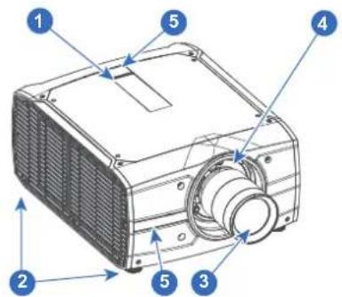
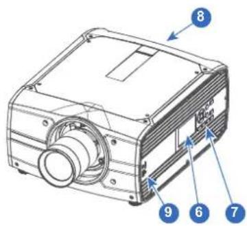
Image 2-2
| Item No. | Item Description |
| 1 | LED Warning Indicator |
| 2 | Adjustable Feet |
| 3 | Lens |
| 4 | Lens Holder |
| 5 | IR Receiver. For receiving remote control signals |
| 6 | LCD Display |
| 7 | Keypad Panel. Used for local operation of the projector. |
| 8 | Connector Panel. Control and communication interfaces for the projector |
| 9 | Front USB and Triggerboard. |
2.2 Service and Maintenance
General
The F70 series does not have any user serviceable parts.
All service tasks must only be carried out by the manufacturer, or a Barco authorized service personnel or Barco technicians.
2.3 LED Status Light
About
The F70 Status Led is located on the rear top of the Projector
During normal operation, the LED is not illuminated. In the event of a critical error or high temperature, the LED will illuminate red.
By critical error, the projector cannot be restarted until the projector is disconnected from the power supply and then reconnected again. If the reason for the error persist, the projector will again go to critical error status.
By high temperature, the projector can be restarted when it has cooled down, and the temperature is back within the normal operating limitations
2.4 Power on / Standby button backlight indications
Indicator
In addition to the LED indicator, the projector also displays status indications in the backlight of the Power / Standby button.
The table below shows the details regarding this indications.
| Operating Status | Indication Color / Behavior |
| On (active) Blue | |
| Wait on Blue flashing | |
| Standby (off) White | |
| Wait White short flashing | |
| Overheating Red flashing | |
| Configure/upgrade White fast flashing | |
| Standby ECO White heartbeat | |
| Software Lockup Red | |
| Severe errors Red Flashing |

When severe errors occur, the failure description will always be available in the notification page in the status menu.
2.5 LCD Panel
2.5.1 LCD panel general
About
The LCD panel (See chapter 2.6, Local Keypad) is located on the right side of the projector, and has two modes of indication; Mirror of the OSD, and Information display.
Toggle between the two indications by using the Menu button on the keypad, or on the remote control
- When mirroring the OSD, the LCD showing the menus and adjustment information.
-
When in information mode, showing this Information regarding the status of the projector:
-
Projector status
• Network address and status - Active source
- Illumination Status
- Current firmware version
• Active functions (Enabled Functions). - Display Info, including Transport delay
- Environment Info.
Use the navigation keys (arrows) to scroll the information menu.
The time before the LCD display fades out is user configurable.
2.5.2 LCD touch panel

The LCD menus can occasionally be slightly different in layout compared with the OSD menu, due to a more optimal layout regarding to the touch functionality of the LCD.
LCD touch panel functionality
In addition to the remote control and the keypad, it is also possible to navigate in the menus with the touch functionality in the LCD panel.
Press the icons to select the functions.
Select switches to toggle.
Select and drag sliders to adjust slider value.
2.5.3 LCD Status screens
Disclaimer on GUI images used in this manual
The GUI images in this manual are example illustrations and should be treated as such. While the name of the projector displayed in the illustrations may be different from the projector model you are currently using, the menu lay-out and functionality is identical.
About
When in information mode, shift between the different pages by using the left or right arrows on the keypad or the remote control. The different pages contain different information, shown in the figures below.
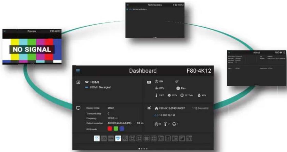
While the projector menu is not active, or the projector is Ready or Standby mode, the Status screens remain visible. These screens give an overview of the state of the projector and can be navigated through using the left and right arrow keys, or by swiping the screen left or right. The status screens are the following:
- Dashboard: The main overview. This screen displays all the chosen options on the projector (chosen source, blending/masking, display mode, etc).
-
About: General info about the projector. This includes serial number, software version, mounted lens and light source runtime.
-
Notifications: The error and/or warning messages that are currently active. If no messages are active, this list will be empty.
- Preview: A preview pane of the projected image. If no image is being projected, a test image is displayed instead.
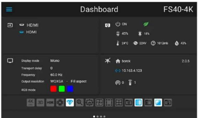
Image 2-1 Dashboard page
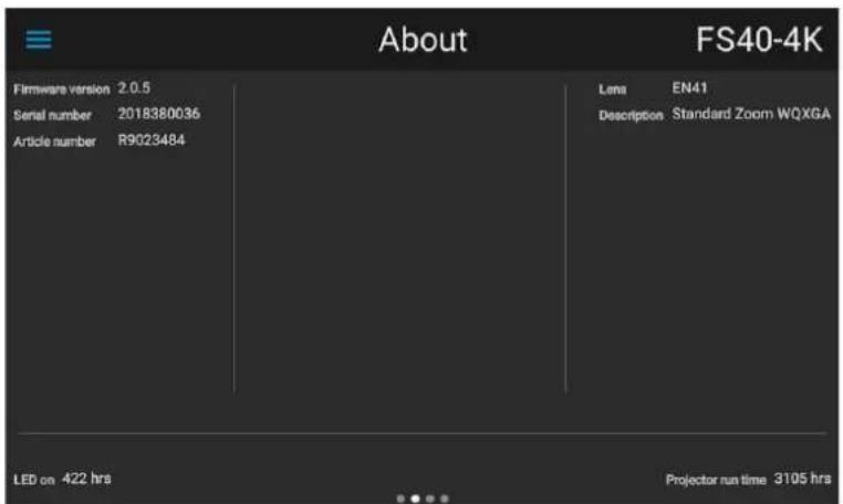
Image 2-2 About page
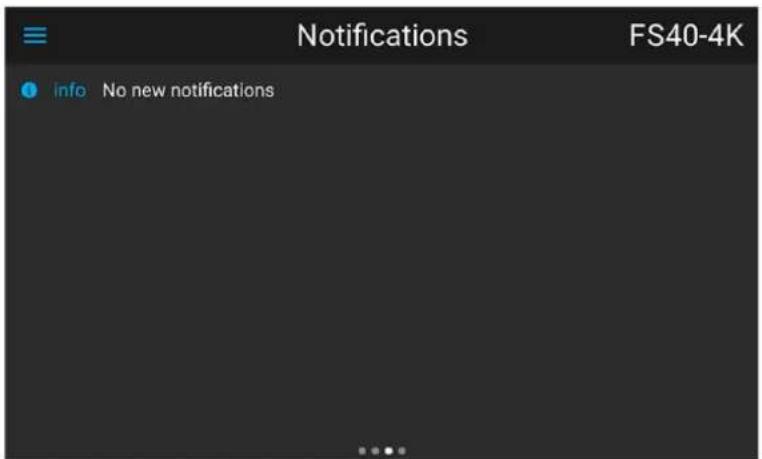
Image 2-3 Notifications page
Getting to know the projector.
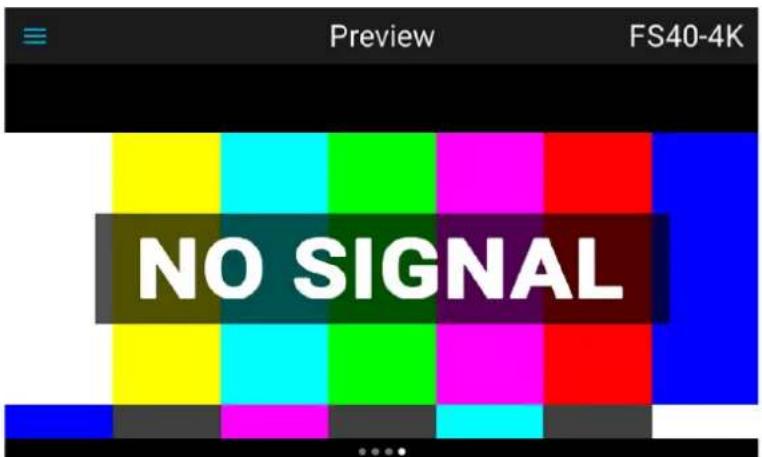
Image 2-4 Preview page
Swipe between the status screens
Due to the touch functionality of the LCD screen, it is possible to swipe between the different pages in the information mode.
flowchart
graph TD
    A["Preview F80-4K12"] --> B["NO SIGNAL"]
    B --> C["Dashboard F80-4K12"]
    C --> D["Display mode Mono"]
    C --> E["Transport delay 0"]
    C --> F["Frequency 126.0 Hz"]
    C --> G["Output resolution 4K/UD (4.074x2.400) - Full as"]
    C --> H["RGB mode"]
    D --> I["ON"]
    E --> J["87%"]
    E --> K["39°C 227V 1017ms 48%"]
    F --> L["F80-4K12:2590148267 1.12.0"]
    G --> M["10.260.28.151"]
    H --> N["0 7 1"]
Image 2-5 Example of a Dashboard status screen
Mirroring the source input. (Preview page).
This page in the information mode is useful for verifying the input signal connection without switching the projector (light source on).
This function shows the output of the currently active source on the LCD panel. The source content should be a picture without warp and blend applied. The picture will be limited by the LCD resolution, 800x480pixels.

The projector performance will drop when the LCD monitoring the input, due to use of resources. Exit the input monitoring when not in use.
2.5.4 Dashboard page symbols
General.
The symbols in the dashboard page gives an overview of which of the projectors features that are enabled. The symbols will mainly occur in the lower row in the dashboard page, but some of them will occur in another position in the same page.
When grey, the function is not enabled.
When blue, the function is enabled. See the figure in chapter "LCD Status screens", page 26 where the dashboard page shows the highlighted Brilliant Color mode, Digital shift and Digital zoom.
Symbol explanations are showed in the figure below.

3D

Blend Black level

Digital Shift

Test Patterns

4K

Blend Files

Digital Zoom

Warp

Black Level

Brilliant Color

HDR

Warp Bow

Black Level files

Feature 16:9

Laser

Warp Files

Blend

Crop

Smear Reduction

Warp Four Corners
Image 2-6 Dashboard Symbols explained
2.5.5 OSD Menu mode
About.
This is the projector setup menus, explained in detail in their own chapters in this manual. (Source menu, Image menu, Installation menu, System Settings menu, Status menu).
2.5.6 LCD functionality in Ready Mode
About
When the projector is in Ready mode, it is possible to activate and navigate in the projectors menu on the LCI display, in order to set or check values and settings before the lamp is switched on.
Ready mode is enabled either when the power cable is connected (after the startup sequence), or when pressing the Power Off for 4 seconds when the projector is in On mode. See chapter 5.4 Power Mode Transitions for a graphic presentation of the ready mode.
Procedure
When in ready mode, press the Menu button either on the remote control, or the keypad to enter the menus. Navigate by using the arrow and OK keys, either on the remote control or the keypad.
2.6 Local keypad
About
The Keypad gives direct access to several functions, in addition to access to the menu system. The keypad and remote control functions are equal.
The keypad has a back light that can be switched on and off manually. The light turns off automatically after a preset time.
Getting to know the projector.
The Standby key is equipped with white, blue and red backlight depending on the status of the projector. See table in "Power on / Standby button backlight indications", page 25 for info regarding this.
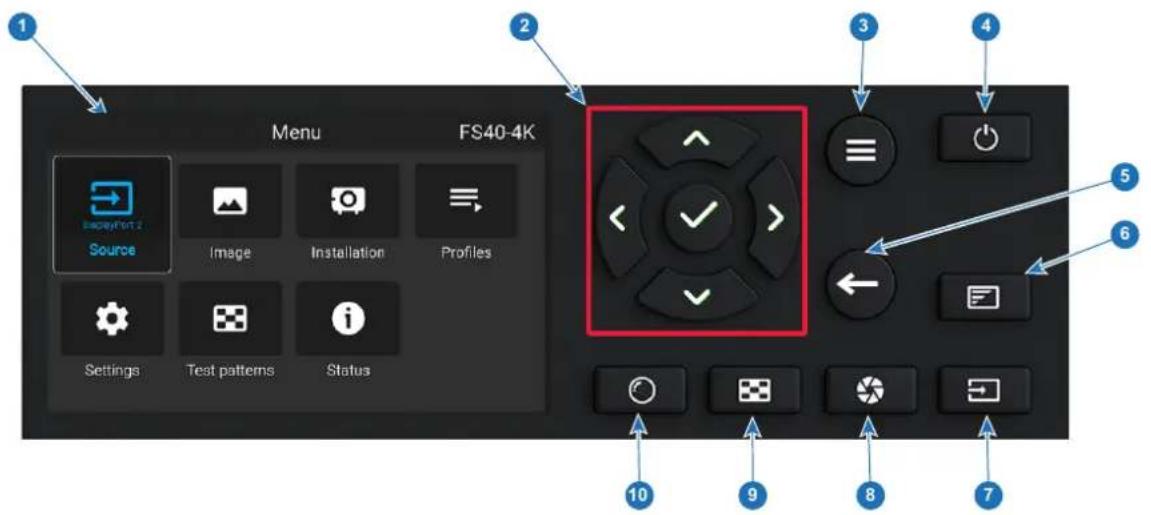
Image 2-7
| Item No. | Name | Description |
| 1 | LCD Display Shows | navigation menu incl. sub menus and projector status screens (dashboard, notification, about and preview). |
| 2 | Navigation keys Navigation arrows (up, down, left, right), confirm selection (√) | |
| 3 | Menu button Toggle | between OSD / Information menu. |
| 4 | Power button Power | on / standby / ready |
| 5 | Back Back to previous screen. | |
| 6 | OSD ON/OFF Deactivate the On Screen Display (OSD). Only critical warnings will be displayed. | |
| 7 | Input Shortcut to input source menu on LCD. Use navigation keys to select and enable input. | |
| 8 | Shutter Enable and disable the lens shutter function. This is not a mechanical shutter, but it toggles the light source on and off. Backlight is red when the shutter are enabled. | |
| 9 | Test Patterns | Shortcut to test pattern menu on LCD. Use navigation keys to select the desired pattern. |
| 10 | Lens | Shortcut to lens function. A test pattern displays on the OSD. LCD screen displays the navigation keys to manage and confirm actions. |
2.7 Shortcut buttons
About the keypad shortcut buttons
On the keypad, there are three shortcut buttons; for lens function, test pattern selection, and input selection. See "Local keypad", page 29 and "Platinum remote control unit", page 32 for location and description. (The remote control has only the test pattern shortcut button).
When the test pattern or input shortcut button is pressed, a pop up menu will show up on the LCD screen. Make a selection by the arrow keys, and confirm.
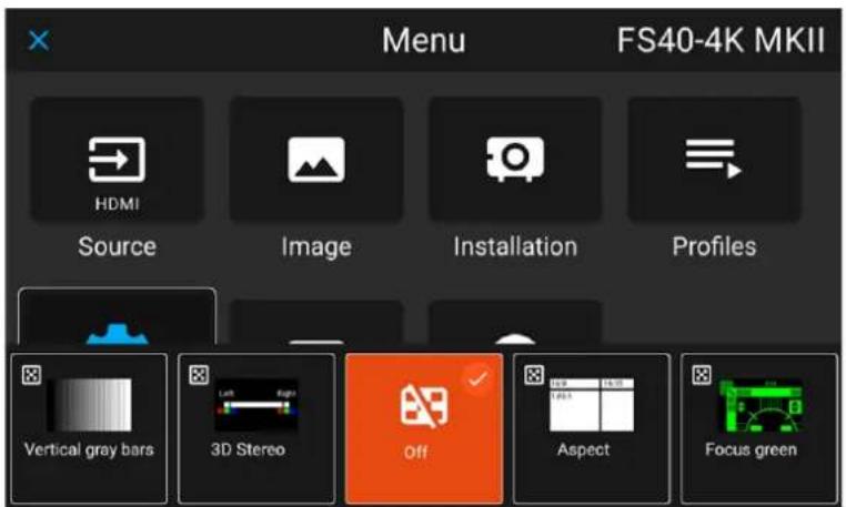
Image 2-8 Test pattern pop up menu
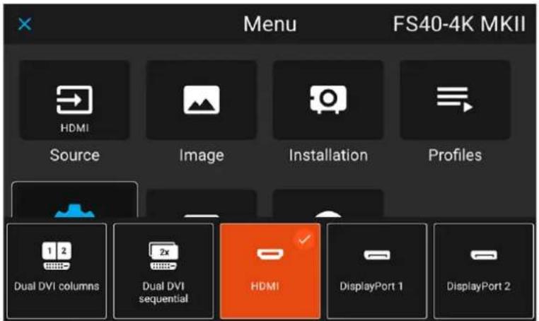
Image 2-9 Input source pop up menu
2.8 Basic remote control unit
About the basic remote
In order to make sure you can control your projector remotely, Barco has provided a basic remote control unit in case the Pulse RCU is not available to you. While this remote control has a more limited amount of available features, it will be able to help you out with basic controls.
Battery placement & replacement
The wireless remote control is powered by two (2) standard AAA batteries.
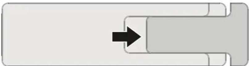
The battery compartment is on the back side of the remote control. The following image illustrates how to open the battery compartment.
natural_image
Pure diagram of a mechanical component with a black arrow indicating direction (no text or symbols)Image 2-10 How to open the battery compartment of the remote

CAUTION: Replace batteries with the correct battery type. Only use AAA size batteries. There is a risk of explosion if the battery is replaced with an incorrect type.
Make sure the polarities match the + and - marks, as depicted on the inside of the battery compartment. There is a risk of explosion if the batteries are installed incorrectly.
Functions
Image
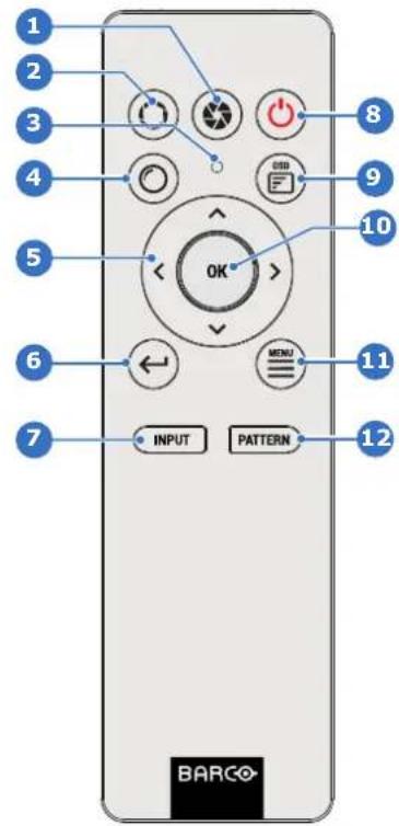
Nr
Description
| 1 Close shutter |
| 2 Open shutter |
| 3 Button pressed indicator |
| 4 Open Lens menu |
| 5 Menu navigation keys |
| 6 Move back one level in menu system |
| 7 Open Source menu |
| 8 Power on / Power offNote: Only shifts power between Ready and ON mode. |
| 9 OSD menu on / off |
| 10 Menu confirmation |
| 11 Activate or deactivate the GUI menu.Note: If pressed while the projector is in stand-by mode, this will also power up the projector. |
| 12 Open Test pattern menu |
2.9 Platinum remote control unit
2.9.1 Remote control, battery installation
Where to find the batteries for the remote control?
The batteries are not placed in the remote control unit to avoid control operation in its package, resulting in a shorter battery life time. At delivery the batteries can be found in a separated bag attached to the remote control unit. Before using your remote control, install the batteries first.
How to install
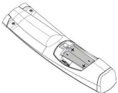
- Push the battery cover tab with the fingernail a little backwards (1) and pull, at the same time, the cover upwards (2).
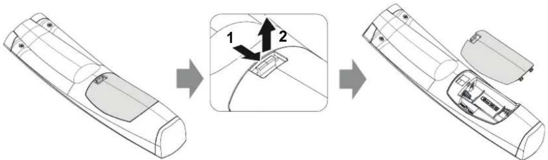
Image 2-1
- Insert the two AA size batteries, making sure the polarities match the + and - marks inside the battery compartment.

Tip: Use alkaline batteries for optimum range and life time.
natural_image
Technical line drawing of a remote control casing with internal compartments and mounting points (no text or symbols)Image 2-2
- Insert (1) both lower tabs of the battery cover in the gaps at the bottom of the remote control, and press (2) the cover until it clicks in place.
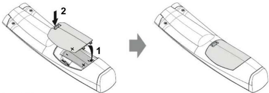
Image 2-3

When replacing batteries, the broadcast address of the RCU will be reset to its default value '0'.

CAUTION: Replace with the correct battery type. Use two AA size batteries
2.9.2 Remote control, protocol setup
About the used protocol
The protocol is the code send out by the remote control when a button is pressed. Depending on this code, the projector can decode the signals. The remote control can be used with two different protocols, RC5 and NEC. Depending on the projector to control, the remote control can be switched between these protocols.
Getting to know the projector.
Which protocol to use
- The NEC protocol have to be used for Barco projectors based on the Pulse platform: Loki, Balder, F40, F70, F80, F90, HDX 4K, UDX, UDM and more.
• The RC5 protocol have to be use all other Barco projectors: HDX W, HDF W, HDQ 2K, ...
How to set
-
Remove the cover. For more info on how to remove, see "Remote control, battery installation", page 32.
-
Place the switch in the NEC position.
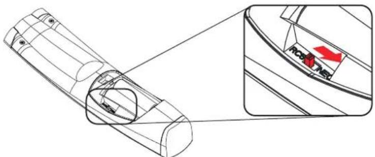
Image 2-4
Remark with RC5 protocol
Not all buttons of the Pulse RCU are one-to-one compatible with the legacy Barco RCU. Button pairs SHUTTER open/close and POWER on/off emit the same code (per pair) when in RC5 mode, because the legacy RCU's only had 1 button for Shutter and 1 button for Standby.
2.9.3 Functionality overview
Remote Control Unit buttons
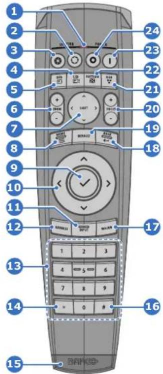
1 Button pressed indicator.
2 Shutter Open.
3 Shutter Close.
4 Touch Panel On/Off. (Not in use).
5 OSD On/Off.
6 Lens Zoom.
7 Lens Shift.
8 Menu Activation.
9 Menu Selection, OK button.
10 Menu Navigation.
11 Input Selection.
12 Address button.
13 Numeric buttons.
14 Backspace (while entering values)
15 XLR connector.
16 Decimal mark (while entering values)
17 Macro button. (Not in use)
18 Menu Back.
19 Default button. (Not in use).
20 Lens Focus.
21 RGB Button.
22 Test Patterns.
23 Power On.
24 Power Off.
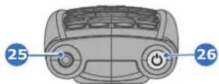
25 Stereo Jack.
26 RCU On/Off.
The projector remote control is a full feature wireless remote control, powered by two (2) standard AA batteries. The battery compartment is on the back side of the remote control.
The remote control is backlit for use in dark environments. It also has an Jack connector for wired connection to the projector. When the wire is connected, the IR beam is switched off.
2.9.4 Pulse RCU, function of the on/off button
Function of the remote control on/off button
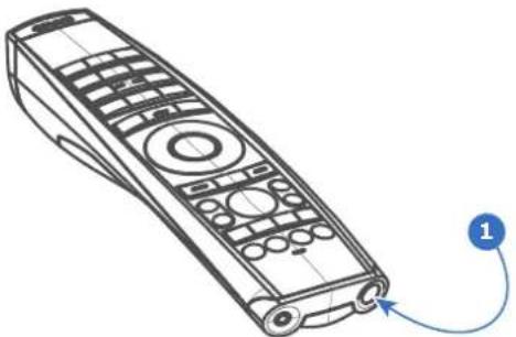
The Pulse remote control unit has at the front side an on/off switch (reference 1 Image 2–5). Switching off the remote control prevents that unwanted commands are send due to an accidental key press. Furthermore, switching the RCU off will extend the battery life time of the remote control.
To activate the remote control, press the on/off button.
To deactivate the remote control, press the on/off button again.
Default after (re)placing batteries, is "ON".
Getting to know the projector.
natural_image
Line drawing of a remote control device with labeled pointer (no text or symbols on the device itself)Image 2-5
2.9.5 Pulse RCU, function of the "RGB filter" button
Filtering the color of the projected image
By pressing the RGB filter button on the RCU you can place a color filter on the output of the projector. This feature can be useful during the installation and configuration of a multi-projector or multi-channel setup. By having one projector project a red image and another project a green image, it is easier to spot and adjust the overlap section.
By pressing this button multiple times, you will have different active filters, in the following cycle:
• Red + Green + Blue (default)
- Red only
- Green only
- Blue only
- Red + Green
- Green + Blue
- Red + Blue
- Red + Green + Blue
• etc

After powering up, the colors will always revert back to full RGB.
2.9.6 Enable / Disable Remote Control
About
This function is for disabling the IR sensors for the remote control. Either front or rear, or both.
Select the menu path Settings/Communication/IR control
Image 2-6

When all sensors are turned off, the projector will not receive any signals from the remote control. To enable the sensors again, use the keypad on the projector.
Select which sensors to be disabled.
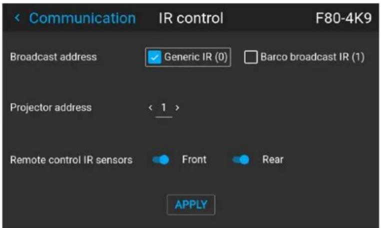
Image 2-7
Enter the Apply button to confirm the action
2.9.7 Wired RC connection
About
The remote control can also be directly wired to the projector from the stereo jack connector on the remote, (See "Functionality overview", page 35), to the RC connector on the back panel of the projector. (See section "Connector Panel")
In this mode, the projector will not be affected by signals from other non-wired remote controls.
When using wired remote control, the broadcast address must be set to "Generic ID (0)". See the menu in "Enable / Disable Remote Control", page 36.
It is not possible to program the remote control in wired mode. (Directly connected, no sense in programming).
2.10 Projector Address

Projector address
Address installed in the projector to be individually controlled.

Broadcast address
Projector will always execute the command coming from a RCU programmed with that broadcast address.
2.10.1 Controlling the projector
Why a projector address?
As more than one projector can be installed in a room, each projector should be separately addressable with an RCU or computer. Therefore each projector has its own address.
Set up an individual Projector Address
The set up of a projector address can be done via the software.
Projector controlling
When the address is set, the projector can be controlled now:
• with the RCU: only for addresses between 1 and 31.
Broadcast Address
Every projector has a broadcast (common) address '0' or '1'. The default address is '0'.
The choice between '0' and '1' can be selected in the GUI: "System Settings" → "Communication" → "IR Control".

Placing new batteries in the remote control or plugging the remote to a projector via a cable will automatically reset the address back to its default value '0'.
2.11 Connector panel
General
The source input panel is located at the back of the projector. For source specifications, see table below.

Image 2-1
| Name Pcs | Description Purpose | ||
| DMX IN 1 | DMX 512 | input For Projector Control | |
| DMX OUT | 1 DMX 5 | 12 output For Projector Control | |
| RS-232 1 | 9-pin DB9 | connector For Projector Control. Allows for wired remote control and monitoring of many projector functions used in installation environments | |
| Sync | 3 BNC Sync Port IN/OUT; Bidirectional mini-DIN (1x 3D sync Out, and 2x Sync In/Out) | For Projector ControlThis is mainly used in multiple projector installations with requirement of synchronization between the units | |
| Trigger | 3 (one in front, two on rear panel) | 12VDC - 0,5A (6W)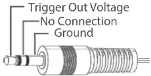 | For Controlling Peripherals, like motorized screens, curtains etc. Give 12V output when activated. See API manual for activation info.NOTE Disconnect the projector power cable before connecting or removing the trigger cable. |
| RC | 1 Jack connector for wired remote | For Projector Control | |
| USB | 3 USB 2 | 0 type A, 4 pin( 2x Rear and 1x Front) | For Software upgrade |
| LAN | 1 Standard RJ45 connector For Projector Control | ||
| DP | 2 Standard display port For Projector Input | ||
| DL-DVI-D | 2 Dual DVI-I 1.0 (DVI_D Functionallity). | For Projector Input. These connectors can also be used to form one uniform image by feeding half of the image into each connector. HDCP compliant for sources up 165 Mhz | |
| HDMI | 1 Standard HDMI 2.0 For Projector Input | ||
| HDBaseT | 1 Standard RJ45 8P8C Connector | For Projector Control | |
| SDI | 2 SDI1 is Input, SDI 2 is pass through. (out) | For Projector Input | |
2.12 Color Wheels
About
The F70 Projector is delivered with a standard Color wheel, that is suitable for most applications.
Other colorwheels are available upon request.
Consult Barco sales office or a service partner in order to find the most suitable colorwheel for the specific application.
2.13 Color Wheel Type
Identifying the installed color wheel
The installed color wheel can be identified in the Status menu.
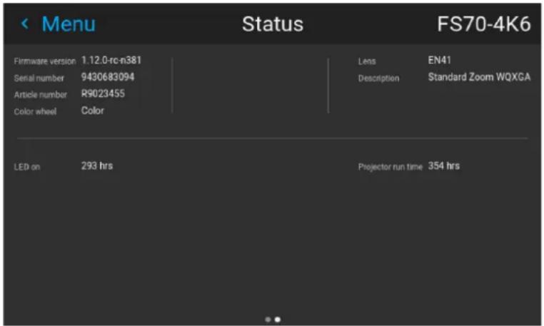
Image 2-2
2.14 Optional Accessories
Rigging Frame
| Item Number | Item Description |
| R9802224 F70/F90 Multifunctional Frame. |
The F70 Rigging frame is a rugged, easy to install frame, designed to streamline the process of installing one or more projectors.
When installed i the frame, the projector:
- can be rotated around the x , y and z axis, in order to obtain a seamless adjustment in applications using multiple projectors.
- Can be installed from a truss or a pedestal.
- Can be easily stacked one on top of another, for instance a dual or multichannel installations.
Flight Case
F70 use the same Flight case as the F90 series projectors.
| Item Number | Item Description |
| R9801195 F90 flight case. |
Getting to know the projector.
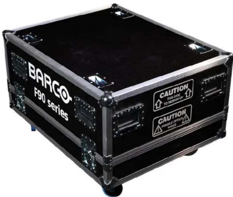
Image 2-3
The F70 Flight Case is a custom designed container, that is suitable for shipping the projector, including flight frame, signal and power cords and up to two lenses.
The case is fully-lined to protect the projector and lenses during transit and storage.
Lenses, Handling and features
3
3.1 Approved Lenses 42
3.2 Lens range....42
3.3 Replace a lens 45
3.4 Lens calibration 47
3.5 Installing the lens safety cable 48
3.6 Preparing the FLDX lens (0.38:1) UST 51
3.7 Mounting the FLDX lens (0.38:1) UST lens with a lens support....55
3.8 Mounting a safety cable to the FLDX lens (0.38:1) UST lens 58
About
3.1 Approved Lenses
Approved Lenses
| Partnumber | Description Compliance | |
| R9801214 FLD 1.6 - 2.32 : 1 (EN11) approved | ||
| R9801218 FLD 0.74 : 1 (EN12) approved | ||
| R9801228 FLD 1.24 - 1.6 : 1 (EN13) approved | ||
| R9801209 FLD 2.37 - 3.79 : 1 (EN14) approved – professional use only | ||
| R9801225 FLD 1:16 : 1 (EN15) approved | ||
| R9801249 FLD 3.8 - 6.5 : 1 (EN16) approved – professional use only | ||
| R9801216 FLD+ 1.7 - 2.5 : 1 (EN41) approved | ||
| R9801226 FLD+ 0.8 : 1 (EN42) approved | ||
| R9801230 FLD+ 1.2 - 1.7 : 1 (EN43) approved | ||
| R9801211 FLD+ 2.5 - 4.6 : 1 (EN44) approved – professional use only | ||
| R9801220 FLD+ Long Focus 0.8 - 1.21 : 1 (EN45) approved | ||
| R9801221 FLD+ Short Focus 0.8 - 1.21 : 1 (EN46) approved | ||
| R9801295 FLD+ 0.65 : 1 (EN47) approved | ||
| PN_EN58 | FLD+ 0.28 : 1 (EN58) approved | |
| R9801832 0.38:1 (WUXGA) 0.57:1 (WQXGA) |
This projector may become Risk Group 3 (RG3) when an interchangeable lens with throw ratio greater than 4.7 is installed.
Refer to the manual chapter 1.7 for the throw ratio versus hazard distance before operation.
3.2 Lens range

CAUTION: Always remove the lens from the lens holder before moving or transporting the projector. Failure to do this may cause damage to the lens holder and prism.
Available lenses — WUXGA
The FLD lens range is custom-engineered for WUXGA and 1080 projectors.
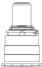
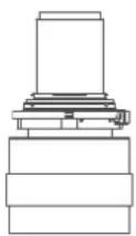
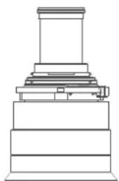
The electrical connection to the lens motors is via a spring probe contact (pogo) pin array on the bayonet mount.
The projector will automatically detect and identify the lens when it is installed. Automatic detection is not available for 3rd party lenses.
EN11
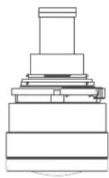
EN12
natural_image
Pure technical line drawing of a stepped mechanical component (no text or symbols)EN13
EN14
natural_image
Pure architectural line drawing of a tiered pedestal or platform structure without any text, numbers, or symbolsEN15
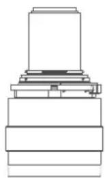
natural_image
Pure mechanical assembly diagram showing layered components without any text, numbers, or symbolsEN16
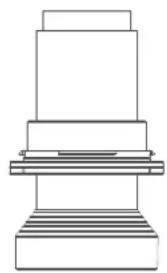
natural_image
Pure technical line drawing of a mechanical assembly (no text or symbols)EN33
Image 3–1
| Name | Description | Part number | Weight |
| FLD Lens 1.6 - 2.32 1 (EN11) | 1.6-2.32 : 1 (WUXGA) R9801214 2.2 kg | ||
| FLD Lens 0.74 : 1 (EN12) | 0.74:1 (WUXGA) R9801218 1.9 kg | ||
| FLD Lens 1.24 - 1.6 1 (EN13) | 1.24 - 1.6 : 1 (WUXGA) R9801228 2.6 kg | ||
| FLD Lens 2.37 - 3.7 : 1 (EN14) | 92.37 - 3.79 : 1 (WUXGA) R9801209 2.5 kg | ||
| FLD Lens 1.16:1 (EN15) | 1.16 : 1 (WUXGA) R9801225 2.4 kg | ||
| FLD Lens 3.80 - 6.5 : 1 (EN16) | 03.8 - 6.5 : 1 (WUXGA) R9801249 2.5 kg | ||
| FLDX Lens 0.38:1 0. | 38:1 (WUXGA) R9801832 6.6 kg |
| Name | Working F# | Iris / Iris F# | Zoom Ratio | Focal Length (mm) | Focus Range (m) |
| FLD Lens 1.6 - 2.32 1 (EN11) | 2.1-2.52 Yes 2 | 1-6.5 1.45 33.2 | 48.1 2.0-15 | ||
| FLD Lens 0.74 : 1 (EN12) | 2.1 | Yes 2.1-6.5 - | 16 | 35 0.5-5 | |
| FLD Lens 1.24 - 1.6 1 (EN13) | 2.1-2.22 Yes 2 | 1-6.5 1.3 | 25.59-33.2 | 4 1.0-15 | |
| FLD Lens 2.37 - 3.7 : 1 (EN14) | 92.1-2.72 Yes 2 | 1-6.5 1.6 | 49.1-78.6 | 3.0-30 | |
| FLD Lens 1.16:1 (EN15) | 2.1 | Yes 2.1-6.5 - | 23 | 98 1.5-15 | |
| FLD Lens 3.80 - 6.5 : 1 (EN16) | 02.1-2.66 Yes 2 | 1-6.5 1.74 78.3 | 136.2 4.0-40 | ||
| FLDX Lens 0.38:1 | 2.4 | No | - | 82 | 1.6 - 5 |
Available lenses — 4K, WUXGA, WQXGA
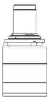
The FLD+ (EN4X) lens range is custom-engineered for WQXGA projectors.
The electrical connection to the lens motors is via a spring probe contact (pogo) pin array on the bayonet mount. The projector will automatically detect and identify the lens when it is installed. Automatic detection is not available for 3rd party lenses.
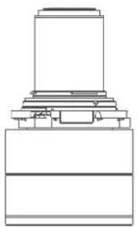
natural_image
Pure technical line drawing of a mechanical assembly without any text, numbers, or symbolsEN41
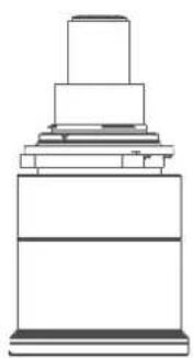
natural_image
Pure technical line drawing of a mechanical component (no text or symbols)EN42 EN43 EN44 EN45 EN46
natural_image
Pure technical line drawing of a mechanical component (no text or symbols)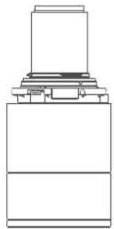
natural_image
Pure technical line drawing of a mechanical assembly (no text or symbols)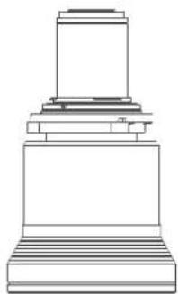
natural_image
Technical line drawing of a stepped pedestal or platform structure (no text or symbols)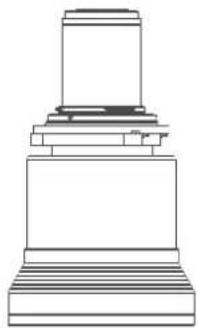
natural_image
Technical line drawing of a mechanical base or platform with stepped base and cylindrical top (no text or symbols)Image 3-2
| Name | Description | Part number | Weight |
| FLD+ Lens 1.7 - 2.5 : 1 (EN41) | 1.58 - 2.33 : 1 (WUXGA) / 1.7 : 1 (WQXGA) | -R9801216 2.54 kg | |
| FLD+ NV Lens 1.7 - 2.5 : (NV41) | IR Optimized, 1.58 - 2.33 : 1 (WUXGA) / 1.7 - 2.5 : 1 (WQXGA) | R9801216 2.54 kg | |
| FLD+ Lens 0.8 : 1 (EN42) | 0.75 : 1 (WUXGA) / 0.8 : 1 (WQXGA) | R9801226 2.7 kg | |
| FLD+ Lens 1.2 - 1.7 : 1 (EN43) | 1.12 - 1.58 : 1 (WUXGA) / 1.2 : 1 (WQXGA) | -R9801230 2.84 kg | |
| FLD+ NV Lens 1.2 - 1.7 : (NV43) | IR Optimized, 1.12 - 1.58 : 1 (WUXGA) / 1.2 - 1.7 : 1 (WQXGA) | R9801286 2.84 kg | |
| FLD+ Lens 2.5 - 4.6 : 1 (EN44) | 2.33 - 4.3 : 1 (WUXGA) / 2.5 - 1 (WQXGA) | -R9801211 3.08 kg | |
| FLD+ Lens 0.75 - 1.13 : 1 (EN45) | 0.75 - 1.13 : 1 (WUXGA) / 0.8 1.21 : 1 (WQXGA) | -R9801220 3.04 kg | |
| FLD+ Lens 0.75 - 1.13 : 1 (EN46) | 0.75 - 1.13 : 1 (WUXGA) / 0.8 1.21 : 1 (WQXGA) | -R9801221 3.14 kg | |
| FLD+ NV Lens 0.8 - 1.21 (NV46) | IR Optimized, 0.75 - 1.13 : 1 (WUXGA) / 0.8 - 1.21 : 1 (WQXGA) | R9801287 3.14 kg | |
| FLD+ Lens 0.65 : 1 (EN47) | 0.61 : 1 (WUXGA) / 0.65 : 1 (WQXGA) | R9801295 5.4 kg | |
| FLDX Lens 0.38:1 0.57:1 ( | WUXGA) R9801832 6.6 kg |
| Name | Working F# | Iris / Iris F# | Zoom Ratio | Focal Length (mm) | Focus Range (m) |
| FLD+ Lens 1.7 - 2.5 : 1 (EN41) | 2.1-2.5 | Yes 2.1-6.5 | 1.47 | 33.70-49.54 | 1.5 - 15 |
| FLD+ NV Lens 1.7 - 2.5 : 1 (NV41) | 2.1-2.5 | Yes 2.1-6.5 | 1.47 | 33.70-49.54 | 1.5 - 15 |
| FLD+ Lens 0.8 : 1 (EN42) | 2.1 | Yes 2.1-6.5 | - | 16.12 | 0.7 - 7 |
| FLD+ Lens 1.2 - 1.7 : 1 (EN43) | 2.4-2.7 | Yes 2.4-6.5 | 1.42 | 23.95-34.02 | 1.5 - 15 |
| FLD+ NV Lens 1.2 - 1.7 : 1 (NV43) | 2.4-2.7 Yes 2.4- | 6.5 1.42 23.95-34 | .02 1.5 - 15 | ||
| FLD+ Lens 2.5 - 4.6 : 1 (EN44) | 2.1-2.93 Yes 2.1 | -6.5 1.85 49.52-91 | .60 2.5-25 | ||
| FLD+ Lens 0.75 - 1.13 : 1 (EN45) | 2.4-3.29 Yes 2.4 | -6.5 1.51 15.85-23 | .93 5.0 - 30 | ||
| FLD+ Lens 0.75 - 1.13 : 1 (EN46) | 2.4-3.29 Yes 2.4 | -6.5 1.51 15.98-23 | .99 0.7 - 7 | ||
| FLD+ NV Lens 0.8 - 1.21 : 1 (NV46) | 2.4-3.29 Yes 2.4 | -6.5 1.51 15.98-23 | .99 0.7 - 7 | ||
| FLD+ Lens 0.65 : 1 (EN47) | 2.1 Yes 2.1-6.0 | - 12.6 0.5 - 4.0 | |||
| FLDX Lens 0.57:1 | 2.4 No - 82 1.6 | - 5 |
3.3 Replace a lens

CAUTION: When installing an EN76 lens, an iris calibration must be performed, see "Lens calibration", page 47
Lens lever
The F70 lens mount and lens lever is designed to prevent damage to the lens board while providing an easy and stable lens change procedure.
The lens lever, located at the bottom of the lens mount, slides between two positions, far left (default position — unlocked) and far right (locked).

Always activate the projector shutter before attempting to remove or install a lens.
To do this, press the shutter button on the keypad, or shutter Close on the remote, to activate the shutter. The keypad button will illuminate red when the shutter is activated.
Press the shutter button again, or shutter Open on the remote, to deactivate the shutter and resume normal operation. The keypad button will illuminate white when the shutter is deactivated.

When changing from a lens with motorized Iris, zoom and focus positioning functionality, to a lens without this functionality (e.g. from a EN 63 to a EN42 lens), it is recommended to power down, and pull the AC cord. This is because the memory of the iris position will not be reset, but will show the position in LCD or OSD for the lens that was removed. When rebooting the projector, the memory will be reset.
The reverse scenario will happen when changing from a lens with no motorized positioning support, to a lens with motorized positioning support. The iris position will not be showed with a correct value. The functionality is still present, but the displayed value is not correct.
Lenses, Handling and features
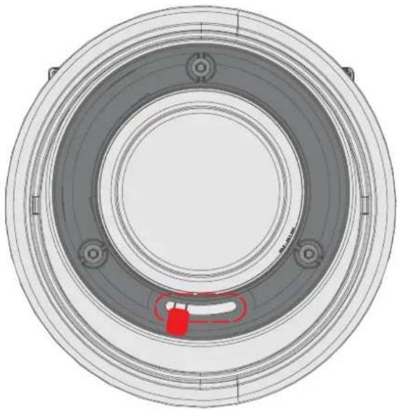
natural_image
Top-down technical drawing of a circular mechanical component with concentric rings and central hub (no text or symbols)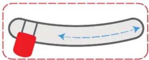
natural_image
Simple illustration of a curved object with a red handle and blue dashed arrow indicating direction (no text or symbols)Image 3-3
Install a lens
- Verify that the projector shutter is activated (shutter is activated when the shutter icon on the projector keypad is red).
- Verify that the lens release lever is in its default position at the far left of the slide, as illustrated.
- Remove the protective cap at the lens bayonet end
- Align the lens so that the red marking on the bayonet is facing upwards.
- Position the lens bayonet into the projector lens mount and support in place with one hand.
- Slide the lens lever to the far right.
- Verify that the lens is firmly in place before removing your hand from the lens.
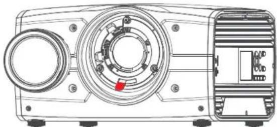
natural_image
Technical line drawing of a mechanical device with circular components and a red indicator knob (no text or symbols)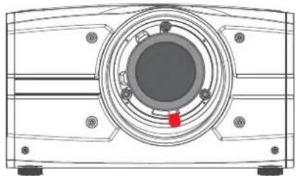
natural_image
Technical line drawing of a mechanical component with concentric circles and mounting holes (no text or symbols)Image 3-4
- In case the projector is mounted above people, it is mandatory to have a lens safety cable installed. See "Installing the lens safety cable", page 48
Remove a lens
- Support the lens with one hand.
- Use the other hand to slide the lens release lever to the far left position.
- Pull the lens straight out of the projector lens mount.
- Replace with another lens, or install the projector lens cap.
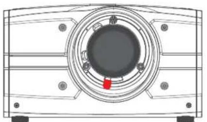
natural_image
Technical line drawing of a mechanical component with concentric rings and mounting holes (no text or symbols)Image 3-5
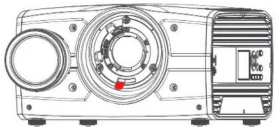
natural_image
Technical line drawing of a mechanical device with circular components and a red indicator symbol (no text or labels)3.4 Lens calibration
When to calibrate the lens
The EN6X series lenses has a functionality that memorize the positions of focus, zoom and iris. In order to obtain the correct position, the lens has to be calibrated when installed.
How to calibrate
Enter the menu Settings / Maintenance / Lens calibration
The calibration menu shows up, with a question mark for each of the functions that has to be calibrated.
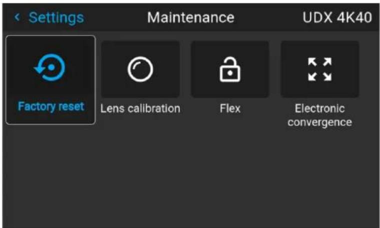
Image 3-6 Focus, iris and zoom need to be calibrated.
Select the first item to be calibrated, and confirm with enter on the remote, keypad or by the touch function.. When the calibration is OK, the question mark changes to a checkmark.
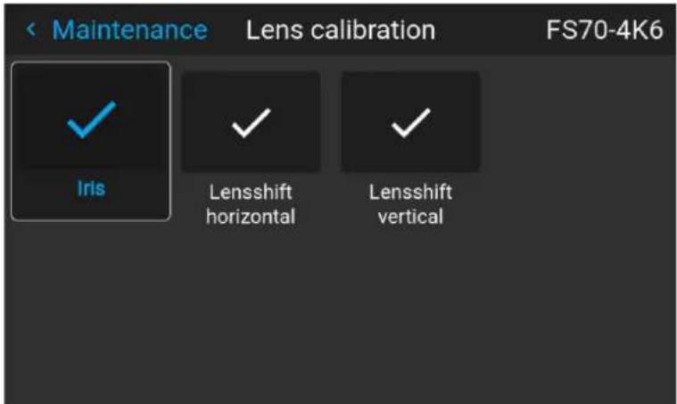
Image 3-7 Select item to be calibrated
Lenses, Handling and features
Repeat for each calibration item.
3.5 Installing the lens safety cable
When to use the lens safety cable
The lens safety cable must be used in any circumstance where the projector is mounted above people. Do this to secure the mounted lens in the lens holder.
Content of the lens safety cable kit (R9801196)
• Safety Cable (750 mm, ∅3 mm)
• Cable clamp M4 (U-bolt)
- Shackle 7x70 mm
• 20 x Cable clip (16x16 mm, ∅4 mm)
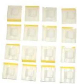
natural_image
Grid of 16 identical square panels with yellow borders, each containing a small white object (no text or symbols visible)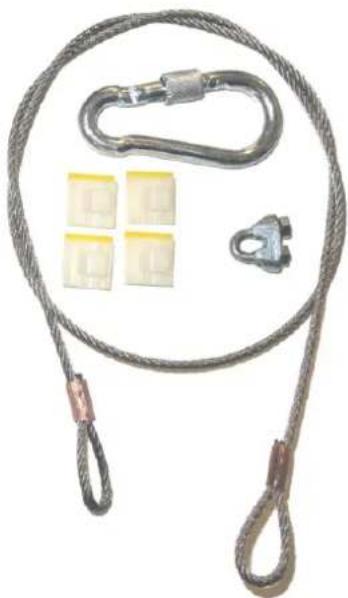
natural_image
Coiled rope with attached metal chain, four yellow plastic clips, and a separate clamp (no text or symbols)Image 3-8
How to install the lens safety cable
- Ensure that the safety cable and its accessories are in good condition (not damaged)
- Paste four cable clips on the lens body between motor block and lens flange as illustrated (reference 1). Orient the open side of the clips towards the front of the lens.
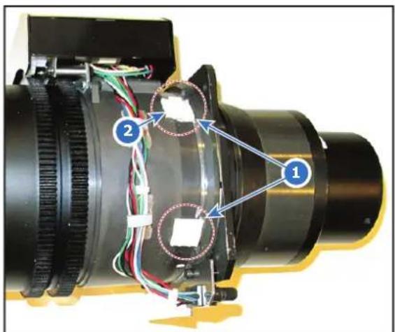
Image 3-9
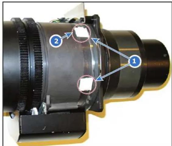
Image 3-10
-
Snap the first loop end of the safety cable into one of the following clips and let the loop end point downwards.
-
Configuration A: Use the upper clip on the side of the cable bundle (reference 2, Image 3–9).
-
Configuration B: Use the upper clip on the non-wired side (reference 2, Image 3-10).
-
Slide the rest of the cable around the lens counterclockwise. Click the cable into every clip it passes in this loop.

Note: Make sure the cable passes between the lens and the cable bundle.
- Slide the cable through the loop end at the beginning of the cable to create a lasso..
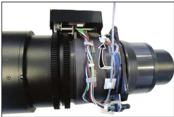
natural_image
Close-up of a mechanical assembly with visible wiring and components (no text or symbols)Image 3-11 Example of configuration A
- Pull the lasso tight around the lens body and install the U-bolt on the lens holder, with the open ends oriented outwards (reference 3). Make sure that both a part of the loop end and the outgoing part of the safety cable are placed in the enclosure.
Lenses, Handling and features
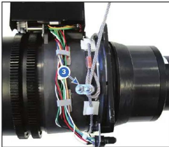
natural_image
Close-up of a mechanical assembly with colored wires and connectors, no visible text or symbolsImage 3-12 Example of Configuration A
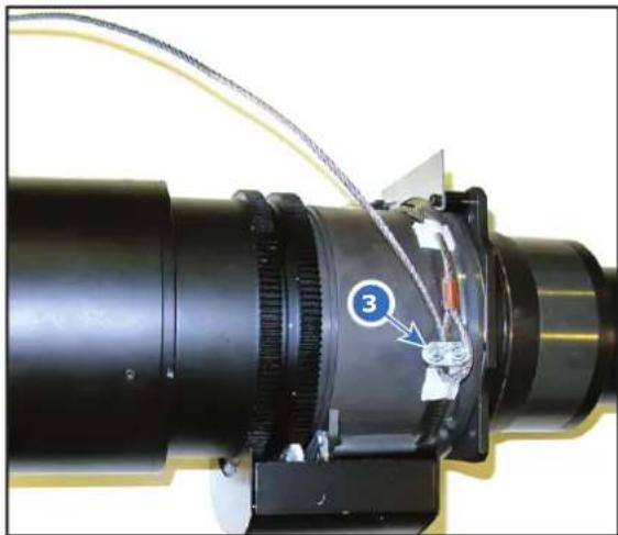
natural_image
Close-up of a mechanical optical component with labeled parts (3), no visible text or symbols beyond the number and arrow.Image 3-13 Example of Configuration B
- Close the U-bolt and tighten it.

Note: Make sure the safety cable is tightened around the lens before tightening the U-bolt nuts.
-
Place the shackle through the free loop end of the safety cable.
-
Connect the shackle on the truss or rigging frame.

Caution: The safety cable is mounted as backup so that the drop distance is as small as possible. Keep the possible drop distance of the lens as short as possible!
How to mount the cable to a short barrel lens
- Paste two cable clips on both sides of the lens as illustrated (reference 1). Orient the open side of the clips towards the outside of the lens.
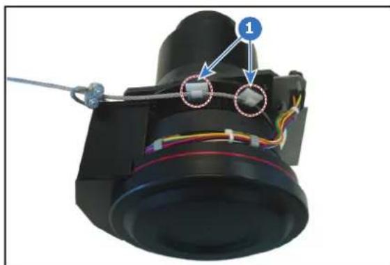
natural_image
Close-up of a camera lens assembly with visible wiring and components (no text or symbols)Image 3-14
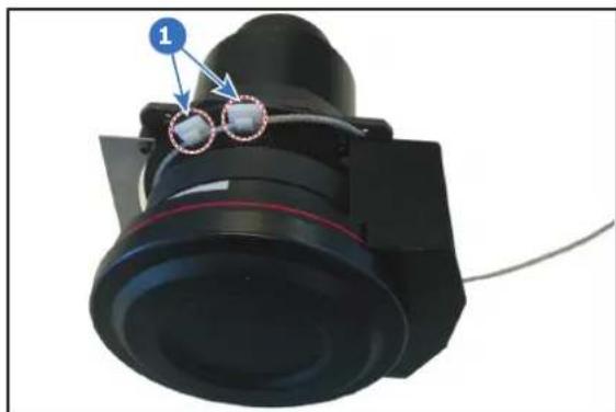
natural_image
Close-up of a black mechanical component with a red ring and blue circular features, no visible text or symbols.Image 3-15
- Paste two extra cable clips on the motor block of the lens. Orient the open side to the outside of the lens.
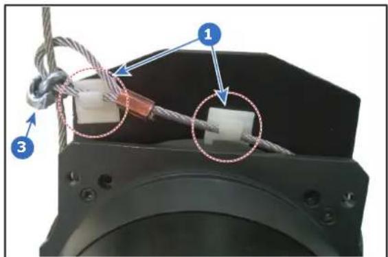
Image 3-16
-
Carefully slide the safety cable through the cable clips. Make sure the cable is placed between the motor block and the cover plate.
-
Slide the cable through the loop end at the beginning of the cable.
-
Mount a U-bolt on the cable, with the open ends oriented outwards (reference 3, Image 3–16). Make sure that both a part of the loop end and the outgoing part of the safety cable are placed in the enclosure.
-
Close the U-bolt and tighten it.

Note: Make sure the safety cable is tightened around the lens before tightening the U-bolt nuts.
The result should look similar to the following example.
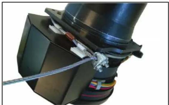
natural_image
Close-up of a mechanical assembly with coiled wires and colored wires, no visible text or symbolsImage 3-17
-
Lead the cable end with the shackle around rigging frame bar or truss bar
-
Snap the shackle to the straight part of the cable.
Secure the shackle by screwing the safety ring of the shackle over the open end.
3.6 Preparing the FLDX lens (0.38:1) UST
Overview
- For F70: facing up and to the left
Lenses, Handling and features
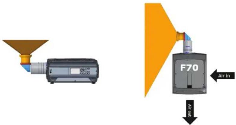
Image 3-18
Do not use for projection to the left when mounted in a frame.
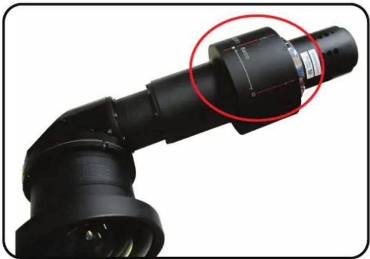
natural_image
Close-up of a black robotic arm joint with a red circle highlighting a specific component (no text or symbols visible)Image 3-19
Required tools
Allen key 2 mm with long shaft (delivered with the kit)
How to prepare the lens
- Place the lens on a table. Turn out the 6 screws (1). Use an Allen key with a long shaft so that you do not damage the screw head. These screws will not be reused.

Note: Always use the correct tool (delivered with the kit) to avoid damage to the screw heads!
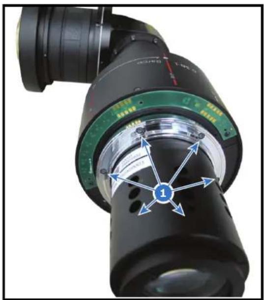
natural_image
Close-up of a black optical instrument with green and black components, no visible text or symbolsImage 3-20
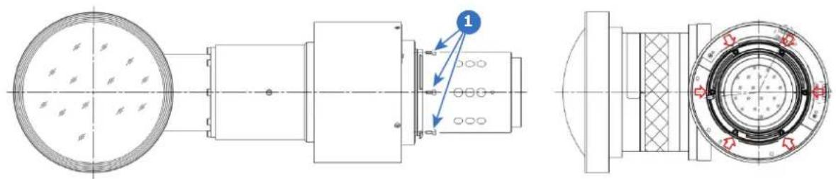
natural_image
Technical line drawing of a mechanical assembly with cross-sectional and top views (no text or symbols)Image 3-21
- Slide the motor housing a few mm to the backside of the lens (2) to disengage focusing gear and motor gear.
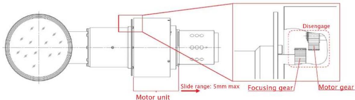
Image 3-22
Lenses, Handling and features
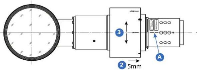
Image 3-23
A reference marking
- Rotate the motor housing until the chosen marker on the housing corresponds with the reference marking on the lens body (steps of 30^ ). See if the mounting holes matches the holes in the lens body. E.g., if you want to project to the left, then turn the motor housing until the left marking on the motor housing corresponds with the reference marking on the lens housing.
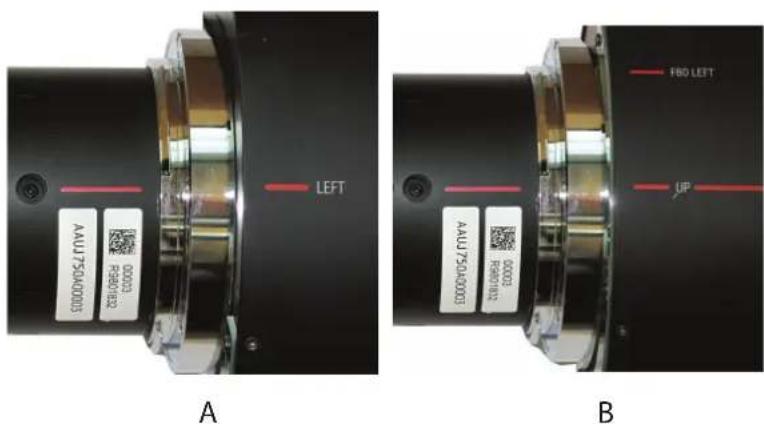
Image 3-24
A Project LEFT
B Project UP
-
Slide the motor housing back to the front of the lens to re-engage focusing gear and motor gear.
-
Turn in 6 new Allen screws with glue (screws are delivered with the kit). These screws can be multiple times reused. The turned out old screws can be thrown away.
Use again a tool with a long shaft (Allen key 2 mm, delivered with the kit).
The lens is ready to be mounted on the projector.
How your image is displayed
Projection to the side for any projector:
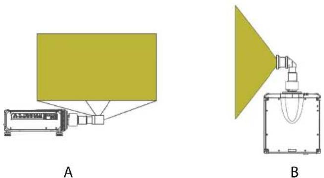
Image 3-25
A Side view
B Top view
Up projection for any projector:
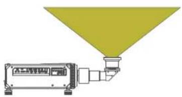
natural_image
Diagram of a device emitting a yellow cone-shaped light source (no text or symbols)C
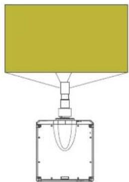
natural_image
Diagram of a mechanical or electrical component with a yellow rectangular block and a central housing, no visible text or symbols.D
Image 3-26
C Side view
D Bottom view
3.7 Mounting the FLDX lens (0.38:1) UST lens with a lens support
How to mount
- Turn the projector on its side or on its top cover.
- Place the bottom support plate on the bottom plate of the projector. Make sure that the fixation holes match the holes in the bottom plate.
Lenses, Handling and features
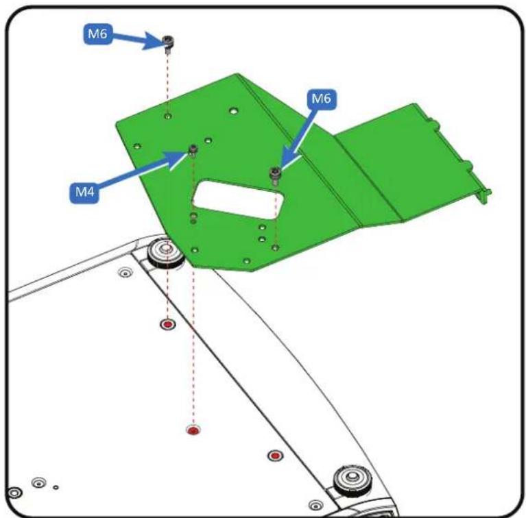
Image 3-27 Mount the bottom plate
- Turn in both M6 screws and the M4 screw.
- Turn the projector back on its feet.
Slide the lens locking system to the left.
Insert the lens. Make sure the electric contact points (C) on the lens match the contact points on the lens holder.
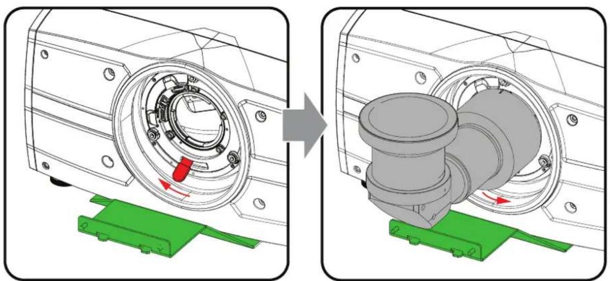
natural_image
Mechanical assembly diagram showing a motor housing and internal components, with no visible text or symbols.Image 3-28 Mount the lens
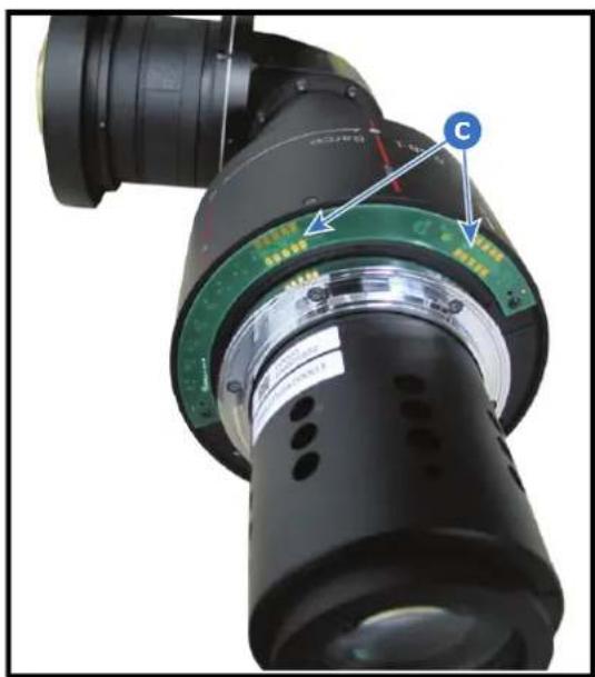
Image 3-29
-
When the lens is on its place, close the lens locking system by moving the handle from the left to the right.
-
Project an image and adjust the shift. See projector's user manual for more information about lens shift.

Note: Shift cannot be adjusted anymore after full installation of the complete kit.
- Slide plate 2 on both threaded rods and turn a nut on each rod. Do not fasten yet! It must be possible to move the plate a little bit while mounting the other plates.
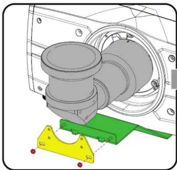
natural_image
Technical illustration of a mechanical assembly with a cylindrical component and two colored metal brackets (no text or symbols)Image 3-30 Mount the 2nd plate
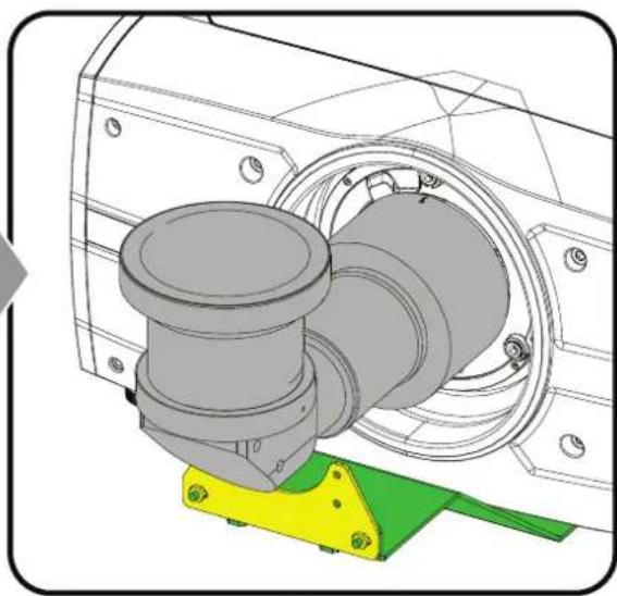
natural_image
Technical illustration of a mechanical assembly with a cylindrical component and mounting bracket (no text or symbols)- Mount the 3th plate on the 2nd plate. Use the upper mounting holes in the 2nd plate. Drive in both screws but do not fasten yet.
Lenses, Handling and features
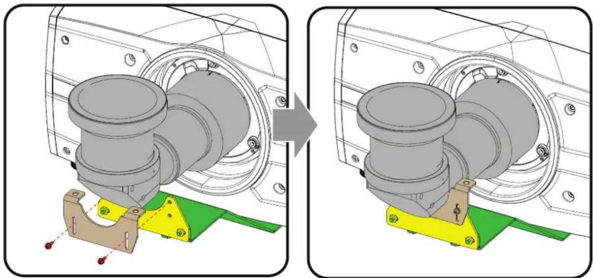
natural_image
Mechanical assembly diagram showing a pipe fitting and mounting bracket before and after modification (no text or symbols)Image 3-31 Mount the 3th plate
- Place the clamping bracket on the lens so that the fixation holes matches the holes in the support.
Drive in both fixation screws. If necessary, move the 3th plate a little bit until it fully match with the lens. Fully secure both screws.
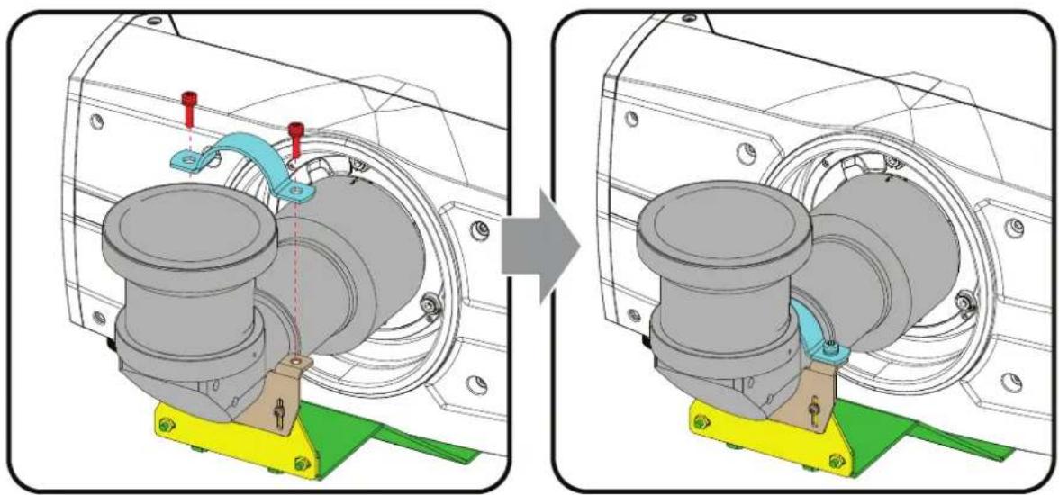
natural_image
Mechanical assembly diagram showing a pipe fitting before and after modification, with no visible text or symbols.Image 3-32 Mount clamp bracket
- Fully fasten the screws of the 3th plate and the nuts of the 2nd plate so that the support is fully assembled. The projector is ready for use.
3.8 Mounting a safety cable to the FLDX lens (0.38:1) UST lens
When to use the safety cable
While it is strongly recommended to use the specifically designed mounting support for this lens in combination with this lens, it is not mandatory.
When mounting the UST lens in a projector without using the mounting support (not recommended), it is mandatory to use the safety cable set provided by Barco instead. Failing to use either the correct type of safety cable or the mounting support may damage the lens and/or projector, and can also cause serious injury to persons.
How to prepare the lens with the safety cable
-
Stick 3 to 4 clips on the surface of the lens body (1).
-
Snap the first loop end of the safety cable into one of the clips.
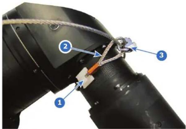
Image 3-33
-
Slide the rest of the cable around the lens. Click the cable into every clip it passes in the loop.
-
Slide the cable through the loop end at the beginning of the cable (2).
-
Install an U-bolt on the lens holder with the open ends oriented outwards (3). Make sure that both a part of the loop end and the outgoing part of the safety cable are placed in the enclosure.
-
Close the U-bolt and tighten it.

Note: Make sure the safety cable is tightened around the lens before tightening the U-bolt nuts.
-
Place the shackle through the free loop end of the safety cable.
-
Mount the lens in the projector.
-
Secure the safety cable around the truss and secure the shackle by turning the safety ring of the shackle over the open end.
Lenses, Handling and features
Physical Installation
4
4.1 Installation process....62
4.2 Installation conditions....62
4.3 Initial inspection....63
4.4 Positioning the projector....64
4.5 Mounting the projector, general considerations 64
4.6 Projector safe attachment points....66
4.7 Throw distance....67
4.8 Scheimpflug (Boresight) introduction....69
4.9 Scheimpflug adjustment procedure 70
About
This chapter describes the physical conditions and procedures required when installing the F70 projector. It also describes the outlines and some of the considerations that should be taken in to account when designing and setting up the installation.
Each projector installation is unique, and as such the information in this chapter is only provided as a guideline. Likewise, any images or graphical representations shown here are for illustrative purposes only.
If you require further information and assistance during the installation process, contact a qualified projection technician or your local support office for advice.
4.1 Installation process
Installation process
- Ensure that the installation area meets all the environmental requirements. See "Installation conditions", page 62.
- Decide the mounting configuration. See "Positioning the projector", page 64.
- Unpack the projector, and confirm that the equipment are present, and in good working order. See "Initial inspection", page 63.
- Mount the projector in the decided orientation. See "Positioning the projector", page 64 and "Projector safe attachment points", page 66.
- Install the lens. See "Replace a lens", page 45. In case of installing an UST lens, see "Preparing the FLDX lens (0.38:1) UST", page 51 and "Mounting the FLDX lens (0.38:1) UST lens with a lens support", page 55.
- Connect the source. See "Getting started", page 73.
- Power up the projector. See "Power up the projector", page 77.
- Adjust and set up the projector. See "Getting started", page 73.

Do not hesitate to refer to the user manual to obtain more information concerning the user interface and supplementary information.
4.2 Installation conditions
Environmental Conditions

Barco projectors are manufactured according to specific design standards, which also include environmental conditions. Failing to follow the terms and conditions outlined in this chapter can result in loss of product warranty
The table below summarize the physical environments in which the projector may be safely operated or stored.
| Environment | Ambient operating temperature | Relative Humidity Storage condition |
| 0 -500m +10 to +45 °C | 10 -80% RH -20 to +60 °C, 10 - 90 % | RH |
| 500 -1500m +10 to +40 °C | 10 -80% RH -20 to +60 °C, 10 - 90 % | RH |
| 1500 - 3000m +10 to +35°C | 10 -80% RH -20 to +60 °C, 10 - 90 % | RH |
| Maximum Air Flow 471m | ^3 /hour 10 -80% RH Not Applicable |

For PRC (People's Republic of China). the certified altitude is specified on the product label.
Mains power requirement
| Projector Power Requirement | |
| F70 | 100 -240V. 50 -60 Hz. |
To protect operating personnel, the National Electrical Manufacturers Association (NEMA) recommends that the instrument panel and cabinet be grounded.
In no event shall this projector be operated without an adequate cabinet ground connection.
The AC supply must be installed by a qualified electrician in conformance to local codes. Hardware, wire sizes and conduit types must comply with local codes.
Ventilation
The free space necessary between the air intake and exhaust are shown below.
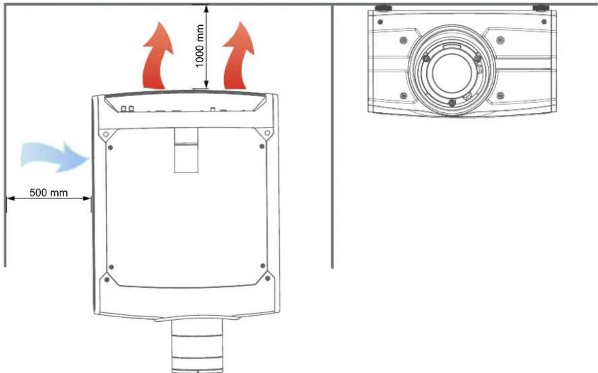
Image 4-1
4.3 Initial inspection
General
Each projector is inspected and rigorously tested at our production facility to ensure that it is free from any mechanical or electrical defects.
Upon receipt of the projector, we recommend that customers inspect the projector for any signs of damage that may have occurred in transit. If damage is found, file a claim with the shipping carrier immediately. Notify the Barco Sales and Service office, or your preferred Barco agent, of the damage as soon as possible.
Box Contents
Your projector box should contain the following:
- Projector unit
- Power cord. (Not all power cords are supplied, see note below).
- Quick start guide
- Safety manual
- Remote Control

If the power cord for your region is not supplied, ensure that the power cord that will be used is according to the regulations for your region. The power cord must be of 3 lead type, where one of the leads is ground. Se also the Safety and Environment Information, chapter 1.2 in this document.

The projector lens is delivered in a separate box.
4.4 Positioning the projector

CAUTION: The position and physical securing of the projector must be sufficient to prevent it from accidental or involuntary movement. Proper securing of the projector is the responsibility of the installer and user. The Projector are heavy, and can cause severe damage and injuries if falling.
General guidelines
Proper positioning of the projector lessens the overall picture setup time, and ensures a better image with fewer artifacts.

Focus and sharpness of the image can be adversely affected if the lens axis is not fully perpendicular to the projection surface.

Using extended cable lengths may result in reduced image quality as well as loss of control information such as EDID (Extended Display Information Data).
The following guidelines can help you determine the best physical location for the projector.
- Only install the projector on a sturdy flat surface, or in an approved rigging frame.
- Do not install the projector in a thoroughfare or another area where it is at risk of being pushed or jostled.
- Allow sufficient free space around the projector for ventilation and exhaust, as described in section 4.2
- Use the throw ratio of the installed lens as a guideline for the projector's physical distance from the screen.
- Wherever possible, the projector lens surface should be positioned so that it is perfectly perpendicular to the center of the screen.
Use the projector offset (lens shift), rather than physical angling, to correct any off-center positioning.
- Minimize the source cable length as much as possible.
In general HDBaseT and 3G-SDI are long-haul interfaces and suitable for bespoke installations using relatively long cables.
DP, HDMI and DVI are short-haul interfaces using pre-assembled cables with limited cable lengths.
- Limit the use of power cable extensions wherever possible. Where physical limitations necessitate their use, make sure that the extension cord has adequate surge protection and meets all electrical requirements of the connection.
- Keep the projector away from equipment that emits electromagnetic energy for example, motors, transformers and elevators.
4.5 Mounting the projector, general considerations
Mounting safety
When mounting a projector in a rig, always use an interface plate (between the projector and the mount) that has provision for a safety wire or another safety mechanism, to ensure that the projector does not fall down should the interface plate come loose from the mount.
Always screw the interface plate securely to the projector body while the projector is on the ground (i.e. cannot fall down). Then attach proper safety wire between the interface plate and the rig before mounting the projector in the rig
Using 3rd party mounting equipment
The projector has features for mounting into various system environments using 3rd party mounts.
The feet can be removed, and the threads can be used as anchor points.
| Item Thread dimension | Max Hole Depth Application | ||
| Removable feet M12 | 18mm | Anhorpoint / | ceiling / rig mount |
In addition, four mounting inserts are located on the bottom of projector. See "Projector safe attachment points", page 66

Where possible, the projector lens must be positioned exactly perpendicular to the center of the screen. Use the projector offset (lens shift), rather than physical angling, to correct any off-center positioning.

CAUTION: The position and physical securing of the projector must be sufficient to prevent it from accidental or involuntary movement. Proper securing of the projector is the responsibility of the installer and user.

CAUTION: Always use a Rigging Frame when the projector shall be mounted in other ways than on the feet, on a flat surface.

The threaded hole in the lower back end of the projector is NOT suitable for lifting or other heavy operations. Only for adjustment purposes.

Installation and use of the Rigging Frame are described in document R5906768 Multifunctional Frame — Installation Manual.

WARNING: Maximum tensile load for each of the anchor points is 62,5 kg. This must be a major consideration when designing the brackets or other arrangements for fixation of the projector.

WARNING: A minimum of 4 anchor points must be used to secure the projector properly. It is strongly recommended to use fixation points with as long mutually spacing as possible, on order to increase mechanical stability of the installation.
Mounting on a flat surface
- Position the projector at the desired location.
- Power up the projector.
- Go to Main Menu / Test Patterns and select an internal hatch pattern to display on the screen.
- Adjust the projector legs until the projected hatch pattern is a level and perfect rectangle.
Adjustable feet
Twisting the adjustable feet in either direction, left or right, allows you to fine-adjust the projector position for precise vertical mechanical alignment.
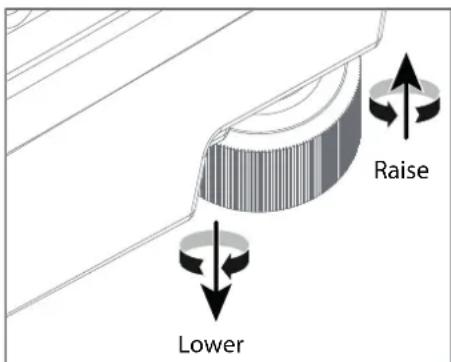
Image 4-2
Mounting to a ceiling
- Install the projector in to an approved rigging frame.
-
Install the rigging frame to the desired location.
-
Power up the projector.
-
Go to Main Menu / Installation / Orientation and select the correct orientation for your setup.
-
Go to Main Menu / Test Patterns and select an internal hatch pattern to display on the screen.
-
Adjust the position (height and angle) of the rigging frame until the projected hatch pattern is a level and perfect rectangle.

If applied in a motion rig, care must be taken to stay within the environmental specifications for vibration and shock. It may also be necessary to use additional, custom means to stabilize the projection lens to make sure that the projected image remains in position and properly focused.
4.6 Projector safe attachment points
About
Due to use of a Rigging Frame or other equipment, the projector has some defines anchor points that shall be used. See the illustration below.
Note that there is only this 4 selected attachment points, in addition to the mounting holes for the feet that is approved as anchor points for the unit.
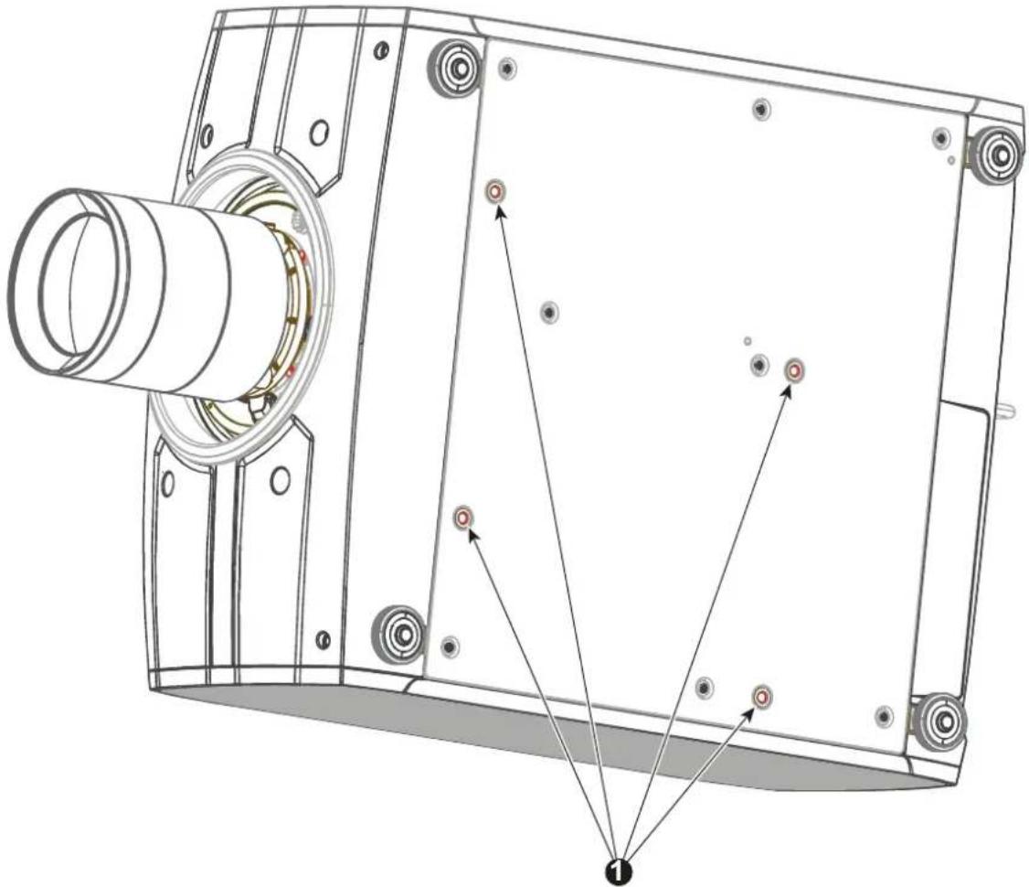
natural_image
Technical line drawing of a mechanical assembly with labeled components (no text or symbols present)Anchorpoints.
For attaching to rigging frame or similar
| Item Thread | Dimension | Max Hole Depth | Application |
| 1 M8 16mm | Anchorpoint / Ceiling / Rig | Mount |
4.7 Throw distance
Calculate the installation throw distance
Throw is the distance (D) measured from your projector lens to the screen. To calculate the throw distance for an installation, you will need two pieces of data: the selected lens throw ratio (L) and the horizontal width (W) of the screen. For example, if the screen width (W) is 2.4 meters and the projector lens has a throw ratio (L) of 0.99:1, then the throw distance (D) will be 2.38 meters.
Calculation: 2.4 x 0.99 = 2.38
The following graphs illustrate the image size (W) and projection distance (D) for each of the projector lenses.

Tolerances are typically +/- 5% due to optical (lens) variation.
Throw distance, FLD WUXGA
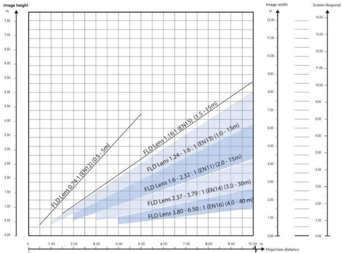
line
| Projection distance | Image height (m) | Image width (m) | | ------------------- | ---------------- | --------------- | | 0.74:1 (EN12) | 0.5 | 0.0 | | 1.16:1 (EN15) | 1.5 | 4.0 | | 1.24-1.6:1 (EN13) | 1.5 | 4.0 | | 1.6-2.32:1 (EN11) | 2.0 | 4.0 | | 2.37-3.79:1 (EN14) | 3.0 | 4.0 | | 3.80-6.50:1 (EN16) | 4.0 | 4.0 |Image 4-4
Throw distance, FLD+ / FLDX WQXGA / 4K UHD
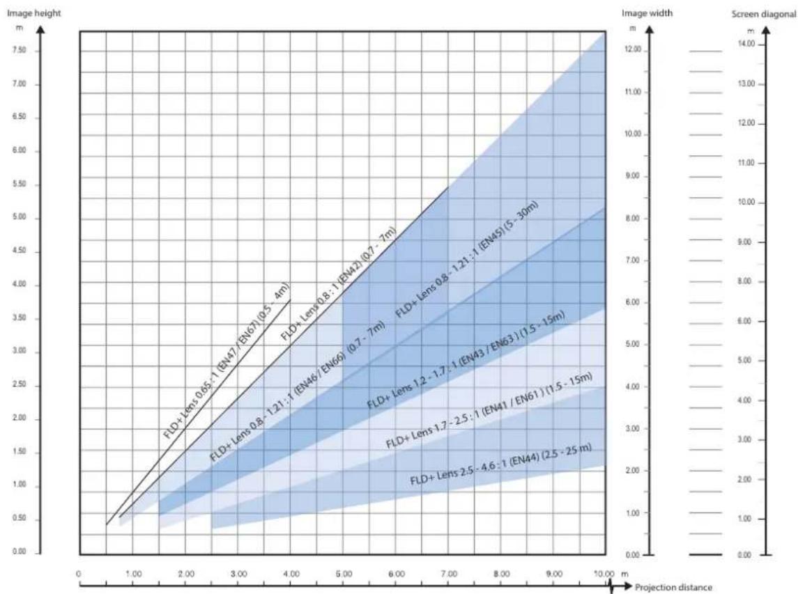
line
| Projection distance (m) | Image height (m) | Screen diagonal (m) | | ----------------------- | ---------------- | -------------------- | | 0.65 | 1.00 | 1.00 | | 0.8 | 1.21 | 1.21 | | 0.85 | 1.21 | 1.21 | | 0.9 | 1.21 | 1.21 | | 1.7 | 2.5 | 2.5 | | 2.5 | 4.6 | 4.6 |Image 4–5
Throw distance, FLD+ / FLDX WUXGA
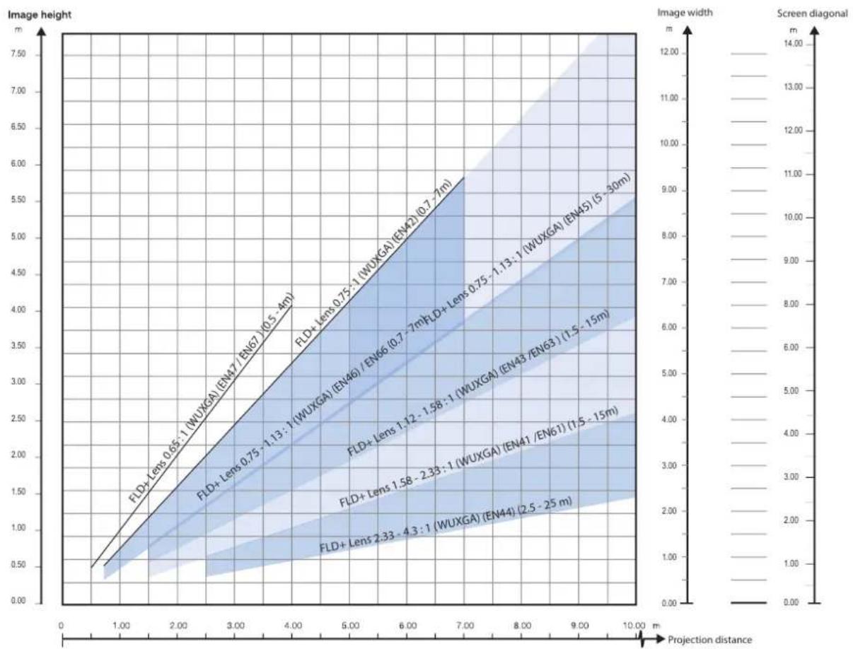
line
| Projection distance | Image height (m) | Image width (m) | | ------------------- | ---------------- | --------------- | | 0.5 | 0.5 | 0.0 | | 1.13 | 1.13 | 1.0 | | 1.58 | 2.33 | 2.0 | | 2.33 | 4.3 | 3.0 |Image 4–6
4.8 Scheimpflug (Boresight) introduction
What is Scheimpflug?
The lens holder has to be adjusted so that the “sharp focus plane” of the projected image falls together with the plane of the screen (Fp1→Fp2). This is achieved by changing the distance between the DMD plane and the lens plane (Lp1→Lp2). The closer the lens plane comes to the DMD plane the further the sharp focus plane will be. It can occur that you won’t be able to get a complete focused image on the screen due to a tilt swing) of the lens plane with respect to the DMD plane. This is also known as Scheimpflug's law. To solve this the lens plane must be placed parallel with the DMD plane. This can be achieved by turning the lens holder to remove the tilt (or swing) between lens plane and DMD plane (Lp3→Lp4).
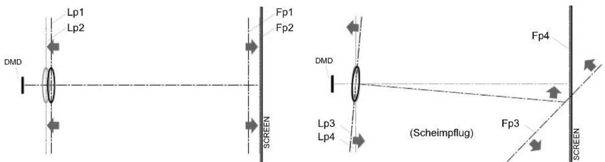
Image 4–7 Scheimpflug principle

Scheimpflug principle
The "plane of sharp focus" can be changed so that any plane can be brought into sharp focus. When the DMD plane and lens plane are parallel, the plane of sharp focus will also be parallel to these two planes. If, however, the lens plane is tilted with respect to the DMD plane, the plane of sharp focus will also be tilted according to geometrical and optical properties. The DMD plane, the principal lens plane and the sharp focus plane will intersect in a line below the projector for downward lens tilt.
Scheimpflug adjustment points
Scheimpflug adjustment points are located on the lens mount. The projector has three (3) set screws and three (3) adjustment screws.
Scheimpflug correction procedures may only be carried out by suitably trained and experienced technicians.
A Scheimpflug correction should only be applied when the overall focus of the projected image is not equally sharp (for example, if the projector is NOT in parallel with the screen or as a result of a previously misaligned Scheimpflug). Be aware that the consequence of applying Scheimpflug correction upon a screen not in parallel with the projector is that the projected image differs from the rectangle shaped image. In other words "distortion" of the projected image occurs. Masking will be required to solve the distortion.
The disadvantage of Masking is loss of content. Therefore it is strongly recommended to place the projector in parallel with the projection screen and use the SHIFT functionality of the Lens Holder to match the projected image with the projection screen. If the SHIFT range is not sufficient then the projector can be tilted and Scheimpflug can be applied.

CAUTION: A Scheimpflug adjustment should only be carried out by properly qualified and experienced projection specialists. A poor Scheimpflug adjustment may result in an extremely degraded image and will require factory—servicing to the projector.
4.9 Scheimpflug adjustment procedure

CAUTION: A Scheimpflug adjustment should only be carried out by properly qualified and experienced projection specialists. A poor Scheimpflug adjustment may result in an extremely degraded image and will require factory—servicing to the projector.
Required tools
- Allen key, hex size 4
- Allen key, hex size 6
Lens distance
Distance from lens to the screen during Scheimpflug adjustment.
| Lens Distance | |
| EN64* 3,0 m | |
| EN76* 2,5 m | |
| All other approved lenses* | 2,0 m |
* With one of these lenses installed, ensure that the white dot (reference 1) on the focus ring is oriented 60 degrees counterclockwise from vertical.
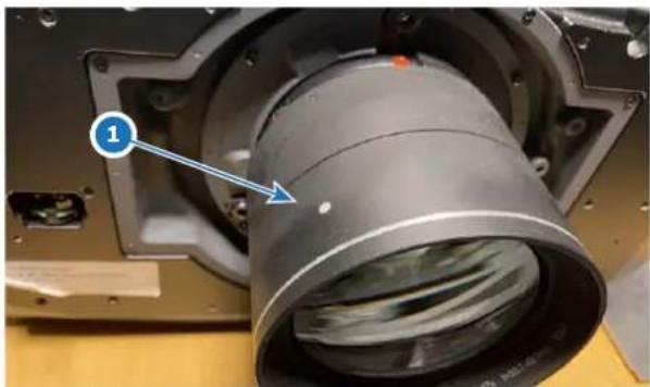
natural_image
Close-up of a mechanical component with a cylindrical housing and labeled part (1), no readable text or symbols present.Image 4-8
Preparation
- Prepare the test area. Barco recommends a projector-screen according to the table "Lens distance" above to be used for all Scheimpflug adjustments.
Verify that the throw ratio of the installed lens matches the requirements of the installation area (projection distance and screen size).
- Check that the lens is correctly installed, and lens shift is in centre position.
- If the installed lens has Iris control, open the Iris all the way up.
- Open the focus ring all the way up.
- Go to Main Menu / Test Patterns / Full Screen and select to display the Focus test pattern.
- Zoom the lens to its widest opening (maximum image size on the screen).
Apply a Scheimpflug correction
- Loosen the three set screws (reference 1b, 2b, 3b). Use a size 6 hex key to do this.
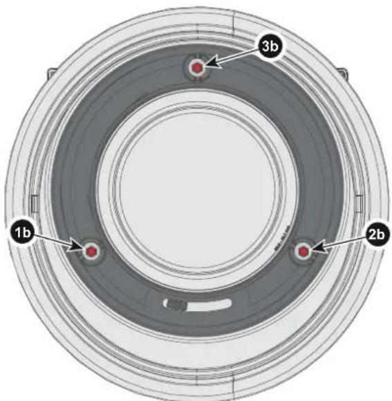
Image 4-9
- Adjust the left side Scheimpflug adjustment screw (reference 1 in the next figure) until the test image in the top left side of the screen is in focus. Use a size 4 hex key to do this.

Note: This process may cause the other areas of the image to slide out of focus. This is totally normal.
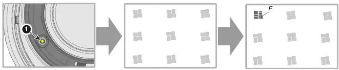
flowchart
graph LR
    A["Circle object with numbered point 1"] --> B["Grid of 8 blocks"]
    B --> C["Grid of 8 blocks with label F"]
Image 4-10
- Adjust the right side Scheimpflug adjustment screw (reference 2 in the next figure) until the test image in the top right side of the screen is in focus. Use a size 4 hex key to do this.

Note: This process may cause the other areas of the image to slide out of focus. This is totally normal.
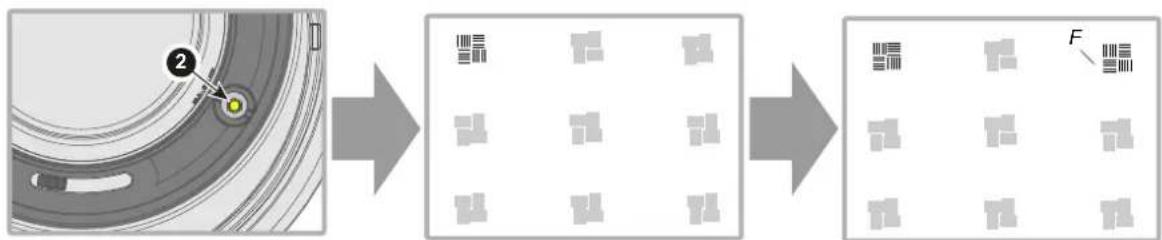
flowchart
graph LR
    A["Circular Object"] --> B["Grid Layout"]
    B --> C["Grid Layout with F label"]
Image 4-11
- Adjust the top Scheimpflug adjustment screw (reference 3 in the next figure) until the test image in the bottom half of the screen is in focus. Use a size 4 hex key to do this.

Note: This process may cause the other areas of the image to slide out of focus. This is totally normal.
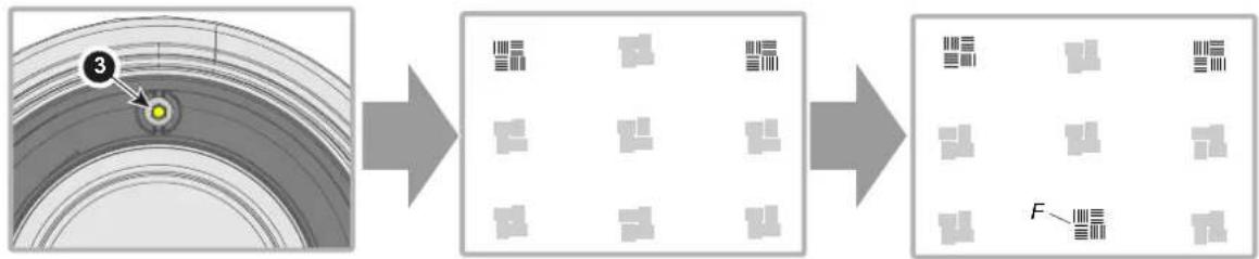
flowchart
graph LR
    A["Initial Circular Structure"] --> B["Transformation"]
    B --> C["Final Pattern with Grid"]
    note["3"] --> A
Image 4-12
- Continue adjusting the screws one at a time until the test image is uniformly sharp across all areas of the display.
- Test the focus by zooming in and out, and verify that the image stays sharp during the complete zoom range. If there are any deviations to sharpness, repeat steps 2 to 6 until the image is correct.
- Tighten the three set screws in the following order: left (1b), right (2b) and then top (3b). Use a size 6 hex key to do this.
Getting started
5
5.1 Projector source and control connections 74
5.2 Power up the projector 77
5.3 Power down the projector....78
5.4 Power mode transitions....78
5.5 Power modes 80
5.6 Customize projector settings 80
5.7 User interface....80
About this chapter
This chapter describes how to set up and optimize your projector setup when the physical installation process is complete.
5.1 Projector source and control connections
5.1.1 Making connections

The source switching time is variable and could take few seconds..
Source signal connectivity
The connector panel at the back of the projector is used for all source connections.
Source signal connectivity on the projector is:
• 2x Dual Link DVI-I (DVI-D functionality)
- 2x DisplayPort 1.2
- 1x HDMI 2.0
- 1x HDBaseT
- 1x SDI input (initially designed for 3G-SDI input signals, 12G-SDI signals are now supported)
5.1.2 Connector specifications
5.1.2.1 Specifications DVI-I inputs
Specifications
| Parameter Value | |
| Connector DVI- I female digital RGB ( DVI-D functionality) | |
| Signal characteristics DVI 1.0, Digital, TMDS | |
| Max. cable length 25 m (24 AWG) | |
| Max. pixel rate 330 MHz (dual link), 165 MHz (single link) | |
| Scan format Progressive | |
| Max. input data resolution 1920x1200 60Hz (Single link)2560x1600 60Hz (Dual Link)1920x1200 @120 Hz (Dual link)1920x2400 @60Hz | |
| Bit depth 8 bit | |
| EDID Supported | |
| HDCP | Supported |
5.1.2.2 Display Port 1.2
Specifications
| Parameter Value | |
| Connector Standard Display port | |
| Signal characteristics DP 1.2 | |
| Functionality | Mandatory |
| Max. cable length 2 m (24 AWG) - RBR; | 2 m (24 AWG) – HBR1, HBR2 |
| Supported Link Rate | RBR, HBR1, HBR2 |
| Scan format Progressive | |
| Max. input data resolution 2560x1600@120Hz WQ | XGA / 3840x2400 @60Hz(4K) Max |
| Bit depth 8, 10, 12 bit | |
| EDID Supported | |
| HDCP Supported |
5.1.2.3 Specifications HDMI 2.0
Specifications

Regarding HDMI 2.0: The decryption protocol HDCP 2.2 are enabled and valid in this unit.
| Parameter Value | |
| Connector Standard HDMI | |
| Signal characteristics Digital, TMDS | |
| Max. cable length 2 m (24 AWG) | |
| Max. pixel rate 594 MHz | |
| Max. input data resolution 3840x2160 @60Hz | |
| Bit depth 8, 10, 12 bits | |
| EDID Supported | |
| HDCP Supported | |
| Ethernet No | |
| Audio return No | |
| HDCP Supported |
5.1.2.4 Specifications SDI inputs
Specifications
| Parameter | 12G-SDI | 3G-SDI |
| Standard | SMPTE ST-2082-1 and ST-2082-10 standards | SMPTE 424M-2006 10bit level A |
| Connector | Samtec BNC7T-J-P-HN-RA-BH1 | 1x) BNC 75 ohm type IEC 60169-8, Amendment 2 1997, A |
| Bandwidth | 12GHz | >3 GHz |
| Return loss | -6dB @ 12GHz | >10dB at 3GHz |
| Impedance | 75 ohm resistive | 75 ohm resistive |
5.1.2.5 Specifications HDBase T input

The HDBaseT standard allows the link to also be used as a regular network port. In addition to carrying video data, it can also be connected to regular ethernet network without carry out any video data.
Due to limitations in the projector and network standards, only the LAN and the HDBaseT should be used for network traffic, but not both simultaneously. If both are connected simultaneously it might lead to undefined behavior where traffic is not being sent on the link indicated by the IPaddress.
This is only valid when the projector has a firmware version 2.1 or higher installed.
Specifications
| Parameter Value | |
| Reference specification HDBaseT 1.0 Specification, | June 2010 |
| Connector Standard RJ-45, 8P8C | |
| Signal characteristics HDBaseT | |
| Max. cable length (1080p/48b/60Hz) 100 m (Cat5e/6), Pixel Clock <=225HHz, Video Datarate <=5.3Gbps70 m (Cat5e/6), Pixel Clock >225HHz, Video Datarate >5.3Gbps100 m (Cat6a/7), Pixel Clock >225HHz, Video Datarate >5.3Gbps | |
| Max TMDS Clock Frequency 270 MHz | |
| Max video resolution supported 4096x2160 @30Hz | |
| HDCP Pass-Through Yes, from Source to Projector | |
| IR Extension Not Supported | |
| RS-232 Extension Not Supported | |
| 10/100Mbps Ethernet Pass-Through Not Supported | |
| Fallback to 100BaseTx, IEEE 802.3u | Not Supported |
| USB Over Centre Tap | Not Supported |
| Power Over Ethernet | Not Supported |
| Audio | Not Supported |
| LEDs - HD Base Status | Operation: Green, LeftLink/Mode: Yellow, Right |
5.1.3 Control interface specifications

The HDBaseT input can also be used as a regular network port. See “Connector specifications”, page 74, HDBaseT specification.
About
This section gives information about interfaces used to control the projector.
5.1.3.1 RS-232
Specifications
| Parameter Value | |
| RS-232 connector 1 female DB9 connector (RS23) | 2-in) for projector control and debug |
5.1.3.2 LAN/Ethernet
Specifications
| Parameter Value | |
| Ethernet connector 1 RJ45 Connector for projector | control (not content) |
| Protocols DHCP, TCP/IP, UDP/P | |
| Speed 10/100 Mbit/1000Mbit |
5.1.3.3 USB-A port
Specifications
| Parameter Value | |
| USB connector Type A | |
| Function Firmware upgrade using USB sticks | |
| Power Power 5V, max 1,5A (out) | |
| Standard USB 2.0 |
5.1.3.4 DMX
DMX interface
DMX is used as communication bus between different devices in the light technic. Each device has an input and an output, so that the bus can be looped between the different devices. According to the standard a five wire cable with XLR connector is used.
You can use the DMX input port to connect a DMX device (DMX console) to the projector. This way you can control the projector from that DMX device (console). The DMX output port can be connected with the next device in the loop.
Pin Description
| 1 | Earth |
| 2 | Cold |
| 3 | Hot |
| 4 | Return - (or not used) |
| 5 | Return + (or not used) |

DMX
DMX-512 Lighting protocol over RS-485 interface. Carries information of 512 channels from a lighting controller to lighting devices. Standardized by USITT.
5.2 Power up the projector

CAUTION: Sources should always be connected before the projector is powered up

CAUTION: Ensure that the main power cord complies with the national regulations where the equipment is used.
Do not use unauthorized replacements.
Do not use power cords which are damaged.
Power up the projector using the keypad or remote
-
Connect the line cord to the projector.
-
Plug the 3-pronged cord into a grounded AC outlet.
The projector will begin warming up, and the backlight of the Standby /power button are flashing white.
-
When the backlight on the standby button are constant white, the projector are in standby mode, ready to be switched on.
-
Press the standby button on the keypad or the power button on the remote to bring the projector up to one mode.
The power button backlight on the keypad will flash blue while the projector is warming up.
- When the power button backlight is steady blue, the projector is ready for use.
5.3 Power down the projector
Power down using the keypad or remote
- Depress and hold the power button on the keypad or remote for four (4) seconds.
The Projector is now in cooling down phase.
- Wait 2 minutes before disconnecting the power cord. (If disconnecting is required).

WARNING: There is a risk of reducing the expected lifetime of the projectors DMD device if the power cord is removed too early, due to the device's shutdown sequence.
5.4 Power mode transitions
5.4.1 General
Transition Diagram
This diagram shows all modes available on the projector (unplug, ON, READY, ECO), and the actions necessary to change mode.
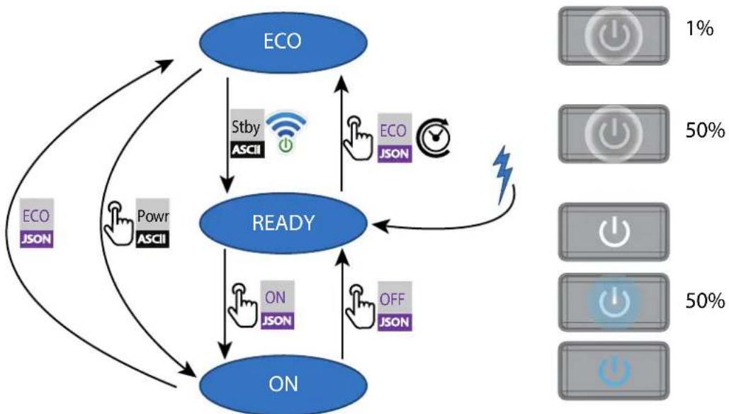
flowchart
graph TD
    A["ECO"] --> B["READY"]
    B --> C["ON"]
    C --> D["ECO JSON"]
    D --> A
    B --> E["STby ASCII"]
    B --> F["ECO JSON"]
    B --> G["ON JSON"]
    B --> H["OFF JSON"]
    style A fill:#000,stroke:#000,color:#fff
    style B fill:#000,stroke:#000,color:#fff
    style C fill:#000,stroke:#000,color:#fff
    style D fill:#000,stroke:#000,color:#fff
    style E fill:#000,stroke:#000,color:#fff
    style F fill:#000,stroke:#000,color:#fff
    style G fill:#000,stroke:#000,color:#fff
    style H fill:#000,stroke:#000,color:#fff
Image 5-1

Projector mains powered

Auto transition after x minutes if ECO mode enables

Press power On/Off button, remote On/Off button
5.4.2 Power on projector

If not already connected, connect the female side of the power cord with the power input socket of the projector. For more details see section dedicated to the power cord installation.
Description
Plug the 3-prong plug of power cord into a grounded AC outlet. The projector will go to READY mode. During this stage the system boots and performs the internal check of the boards. The Power On/Off button will BLINKING WHITE until READY mode is achieved. Once in READY mode, the Power On/Off button will be lit WHITE.
5.4.3 Going from READY to ON
Description
Press the Power On/Off button on the projector, or the Power On button on the remote control. The projector will power ON. The Power On/Off button will BLINK BLUE during the transition from READY to ON. Once the projector is on, the Power On/Off button will be lit BLUE.
5.4.4 Going from ON to READY
Description
Press and hold the Power on/off button on the projector for 4 seconds, or press the Power Off button on the remote control. The projector will power down through a cool down phase. The Power on/off button will BLINK WHITE during the transition from ON to READY. Once the projector is in READY, the Power on/off button will be lit WHITE.
5.4.5 Going from READY to ECO standby
Description
If ECO Standby mode is enabled in the service menu (refer to the section "GUI - system settings/Standby ECO", in User Guide) the projector will automatically go to ECO standby mode after a time-out (default 15 minutes). All electronics (including fans, pumps,...) go down except for a very small wake up controller. The Power on/off button will FLASH WHITE every second.
5.4.6 Going from ECO to ON
Description
Press the Power on/off button on the projector, or the Power On button on the remote control. The projector goes from ECO directly to ON. The projector will go through the same booting phase as on power plugging, then do the transition from READY to ON. Of course startup-time will be longer then from READY to ON.
5.4.7 Wake On LAN (WOL)
About
The projector has WOL functionality, that can be used for the projector to go from ECO mode to READY mode. Use a json command for transition from READY to ON.
The WOL is performed by sending a Magic Packet followed by the projectors MAC address. The MAC address is found in the Menu / Settings / Communication / LAN. menu. The MAC address is similar to the HW address that is shown in this menu path.

The LAN cable must be connected when the projector enter the ECO mode, in order to obtain the Wake on LAN function.
5.5 Power modes
General
The table below details the projector power modes.
| Mode | Description |
| Normal Projector is booted up and the light source | is on |
| Ready Projector is booted up but the light source | is off |
| ECO Standby Light source is switched off and projector electronics are powered down | |
5.6 Customize projector settings
About
The projector display, behavior and user interface can be adjusted to meet individual requirements.
Options include:Menu/Settings/Themes
- Adjust the OSD menu color
5.7 User interface
5.7.1 On Screen Display (OSD)
About
The projector on screen display (OSD) is the primary user interface (UI). From here, you can review and adjust all projector and display settings.
The OSD interface uses tabs to display the main menu. Topics are then further sorted and displayed by function: main (topic) — sub (function) — sub (function).
There are seven main menu tabs: Source, Image, Installation, Profiles, Settings, Test pattern and Status.
The OSD can be disabled by pressing the OSD on/off button.

In order to show the OSD, the OSD On/Off button must be disabled. (White backlight on the button). When the button have blue illumination, the OSD will not appear, and the display information are only visible on the LCD Display. Only Critical warnings will be displayed.
User access levels
The projector's software platform uses access levels to define what each user can do.
There are two user access levels: Standard User and Power User. In addition, there is a Service user access for certified Service personnel.
A standard user has access to all projector functionality and OSD menu items. A power user has, in addition to access to all projector functionality and OSD menu items, access to a number of advanced functions. Access to power user features is password-protected. Contact your projector supplier for more information.
Navigation
You can navigate the OSD using the local keypad or the remote control.
Press the MENU button to display the OSD. (The OSD must be enabled, press OSD button to enable.)
Use the arrow keys to navigate left, right, up and down.
Press the OK button to select a menu topic and get more options.
Use the numeral keys to enter values, or use the arrow keys to move the barscale up or down.
Press MENU again to exit the menu system.
Press the OSD button to deactivate the OSD on the screen. Only critical warnings will be displayed.

Some menu options are reserved for Power or Service Users; these will be grayed out and not available for selection when in standard user mode. To access these features, enter your Power or Service Code in the Service Menu or contact your support representative for more information.
Define values
Menu settings are displayed using checkboxes, barscale sliders, and selection boxes, depending on the type of menu.
To set a value:
- Press OK to select or deselect a checkbox (turn a function ON or OFF).
- Use the arrow keys to move the barscale slider up or down on the value line. For a barscale 0-9, each step will equal 10% of the total value.
- To enter the value as a direct number, press ENTER, input the digit(s), and then Press ENTER again to execute and exit cursor mode e.g. ENTER 79 ENTER.
Changes to values are implemented dynamically.
Menu memory
The OSD menu remembers the last selected sub-item as long as the projector is running. The menu memory is reset when restarting the projector from standby.
Source menu
6
6.1 Connector selection....84
6.2 Connector settings....84
6.3 Using dual inputs....86
About the Source menu
This menu is used to select, review and configure sources into the projector. Enables either via the source menu, or the shortcut key.
By navigate through the Source menu, it will be visible also on the OSD.
By using the shortcut key, the menu occurs only on the LCD display.
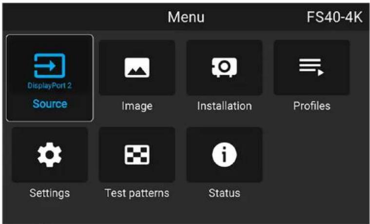
Image 6-1
6.1 Connector selection
About
Home/Source
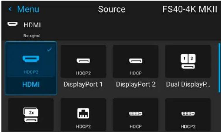
Image 6-2

Observe that the HDCP compatibility for each input is noted in the input icon. See chapter 5.1 "Projector source and control connectors". for input source specifications.
Click on the relevant input connector icon to swap or activate the source.
The icon for the active source is highlighted.
The list of displayed sources can be adjusted to include other connectors.
The default selection of connectors displayed is:
- HDMI
- Display Port 1
- Display Port 2
• Dual Display port Columns
• Dual Display port Sequential - HDBaseT
• DVI 1
• DVI 2 - Dual DVI Columns
• Dual DVI Sequential - Connector settings
6.2 Connector settings
About connector settings
The Connector Settings menu allows you to change settings for each input connector of the projector.
By default all options for every connector are set to automatic, together with the native Extended Display Identification Data (EDID).
When entering the menu for each input connector, you can change the following:
- Color Space
- Signal Range
• EDID
How to configure a connector
- Press Menu to activate the menus and select Source.
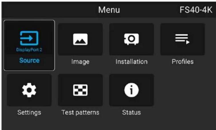
Image 6-3 Select source
- Press OK.
The Source menu is displayed with the actual available sources filled out.
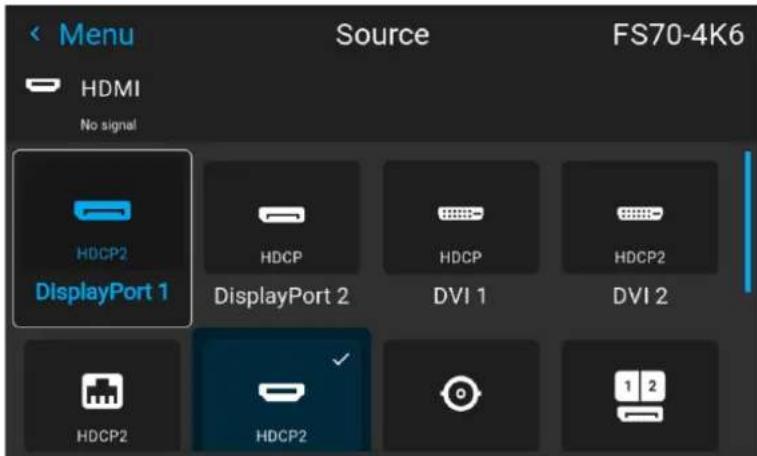
Image 6-4 Source menu
- Scroll down to the bottom of the list of available sources and select Connector Settings.
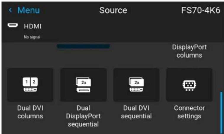
Image 6–5
The available input connectors are displayed.
- Select the desired connector.
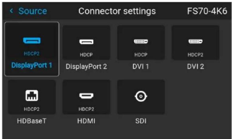
Image 6-6
The Connector Settings menu for this connector will be displayed.
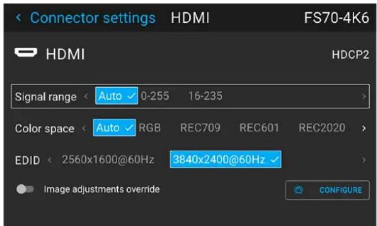
Image 6-7 Example of connector settings of an Displayport Connector.
-
You can change the following:
-
To force a limit on the color space, select one of the available color spaces.
• To force a limit on the used signal range, select one of the available signal ranges.
• To set a video timing other than the one native for the connector, select one of the options under EDID.

Note: You cannot change the EDID for SDI connectors.
6.3 Using dual inputs
Dual Input.
For extended flexibility to connect high resolution sources with a pixel clock over 330 MHz, the projector is supporting a dual input mode. In this mode, the left and the right half of the image can be connected to the DVI-1 and DVI-2 respectively, or DP1 and DP2.
To enable this mode, select the source that fits in the Menu/Source
Dual input modes
There are four ways to connect dual input.
• Dual Displayport Columns
• Dual Displayport Sequential
- Dual DVI Columns
- Dual DVI Sequential

For Images to be displayed in this mode, the resolution must be the same on both channels
Signal source setup.
When using dual inputs, it is important that the signal sources are set up correctly, with the correct resolution. Please refer to the manual for the source itself (PC, Graphic driver card..) in order to obtain a correct setup. If the setup is wrong, no picture will be visible in dual mode.
The resolution for each dual column channel can be up to 1920x2400 pixels.
The resolution for each dual sequential channel can be up to 2560x1600 pixels. (4K)

Change the EDID for each channel to the correct value. See chapter "Connector Settings" for EDID setup.
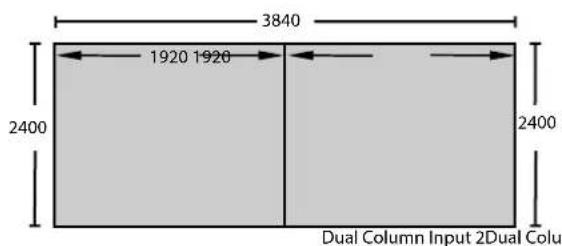
Image 6-8 Dual Column Setup
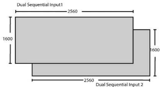
Image 6–9
Image menu
7
7.1 Contrast....91
7.2 Brightness....91
7.3 Saturation 92
7.4 Sharpness 92
7.5 Gamma adjustment 93
7.6 Gamma Types....94
7.7 Digital Zoom Shift 95
7.8 Advanced image adjustments....97
About Image adjustment menus
There are different menu pictures showing up for the LCD display and the OSD. For the LCD display, the menu is shown below. The OSD menu is shown in the different topics below, and is visible in the lower left corner of the screen. The operation of the menus can be done with both the remote control or the arrows on the keypad. It is also possible to switch between the different adjustments by using the up and down arrows, instead of exit one menu and then enter the next one.
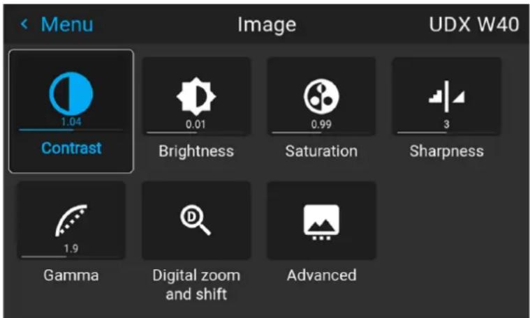
Image 7-1
Entering Contrast, Brightness, Saturation, Sharpness or Gamma menus from the keypad.
When entering any of these menus from the Keypad, the screen below will show up in the LCD panel. Use the arrow keys to select and adjust the values.
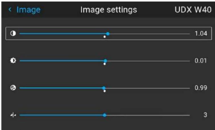
line
| Image Settings | Value | | -------------- | ----- | | 1 | 1.04 | | 2 | 0.01 | | 3 | 0.99 | | 4 | 3 |Image 7-2
When pressing enter on the value slider, this icon will show up on the OSD (depending which setting that is enabled, contrast showed here). When in this mode, use the up and down arrow keys to navigate between the different settings.
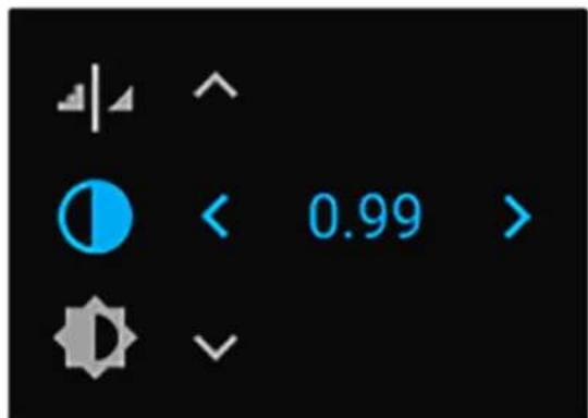
Image 7-3 OSD menu
7.1 Contrast
About
Image / Contrast
Used to adjust the contrast ratio of the displayed image by applying gain to the red, green and blue signals.
Available range: 0.00 to 2.00
Default value: 1.00
Image 7-4

When inside this menu, it is possible to change to the other image adjustments (Brightness, Saturation, Sharpness and Gamma) by using the up and down arrows on the remote control or keypad.
7.2 Brightness
About
Image / Brightness
The brightness function is used to adjust the black level in the input picture. It adds or subtracts an offset, or bias in to the red, green and blue signals.
Available range: -1.00 to 1.00
Default value: 0.00
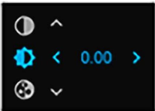
Image 7-5 Brightness OSD menu
7.3 Saturation
About
Image / Saturation
Saturation levels impact on the white levels and the intensity of the color display; the higher the value, the more vivid the color display will be.
Available range: —1.00 to 2.00
Default value: 1.00
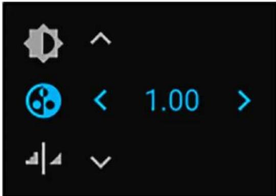
Image 7-6 Saturation OSD menu
7.4 Sharpness
About
The sharpness adjustment amplifies the high frequency components in the picture, meaning that by increase the sharpness, the picture will be perceived as sharper, and if decreased, the picture will be perceived as more blurry.
Increasing the sharpness will have the best effect in high contrast images, eg a table with text and borders. In a natural picture, high sharpness can be perceived as noise, as all details in the picture will be amplified. Available range —2 to 8.
Default value: 0
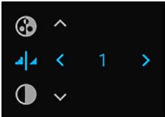
Image 7-7 Sharpness OSD menu
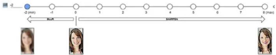
flowchart
graph LR
    A["-2 (min)"] --> B["-1"]
    B --> C["0"]
    C --> D["1"]
    D --> E["2"]
    E --> F["3"]
    F --> G["4"]
    G --> H["5"]
    H --> I["6"]
    I --> J["7"]
    J --> K["8 (max)"]
    style A fill:#000,stroke:#fff,color:#fff
    style K fill:#000,stroke:#fff,color:#fff
    subgraph Time_Steps
        L["Image 1"] & L["Image 2"] & L["Image 3"] & L["Image 4"] & L["Image 5"] & L["Image 6"] & L["Image 7"] & L["Image 8"]
    end
    L -->|Blue/Red| L
    L -->|Black/White| L
Image 7-8 Effect of sharpness adjust
7.5 Gamma adjustment
About gamma correction.
Gamma compensation, or gamma correction, is a way of adjusting the signal input to light output characteristics of a display or projector in order to suit the eye's sensitivity to different light levels and to compensate for non-linearities in displays. Without gamma compensation, images may look too dark or too bright, lack detail or depth. By adjusting the amount of gamma compensation changes, you change only the perceived brightness levels.
Different types of displays have different gamma factors that need to be corrected in order to look and be perceived the same. For example, an MS Windows generated image displayed on a CRT monitor will require a gamma correction value of about 2.5 to avoid color bleaching and burning.
The gamma curve correction formula is based on output level input level gamma.
How to adjust
- Enter the Image menu, and select Gamma.
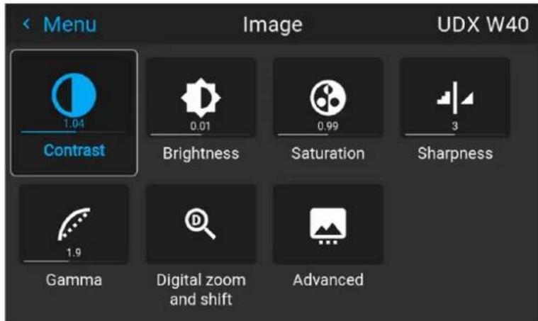
Image 7-9
-
Use the arrow keys to select the most suitable gamma type.
-
Select the gamma slider and tune the gamma value.

Note: The Gamma slider in the Gamma menu will be disabled when DICOM, SIM or SRGB values is selected.
Image menu
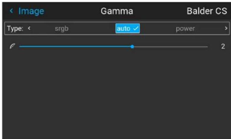
Image 7-10
7.6 Gamma Types
7.6.1 Predefined Gamma types
About
The Gamma Type selection contains several predefined Gamma settings for the most common user cases.
How to select Gamma type
-
Enter the menu Image / Gamma
-
Press enter, and scroll horizontally in the menu and select the proper Gamma value.
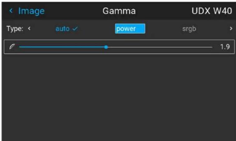
Image 7-1
- Select the gamma type that match the setup in the source to obtain an optimal rendering.
7.6.2 DICOM Gamma

This function is not intended for determination of medical diagnoses.
Purpose
DICOM gamma type will not make the projector a fully certified as a medical display. For that purpose, a type of calibration must be performed, which the projector does not support.. Because of that, this function is mainly intended for educational and lecture purposes.
The DICOM function is used to simulate DICOM gammas at a few selected max light outputs, and assumes that both ambient light and the projector black is 0 cd/m2.
How to select the optimal DICOM Gamma
-
Enter the menu Image/Gamma
-
Scroll horizontally in the menu and select a DICOM value that is closest to the value from the source. (If the source is set up with a value of 270, select DICOM 250 from the drop down menu). Higher numeric value represent a brighter environment.

Note: The Gamma slider in the Gamma menu will be disabled when DICOM, SIM or SRGB values is selected.
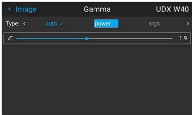
Image 7-2
- Verify that the selected value gives a proper rendering of the image. If not, select another value.
7.7 Digital Zoom Shift
About
The digital zoom and Digital Shift functions are both entered from the same menu. The menu shows how to toggle between zoom and shift adjustment.
Enter the menu shown below, either via the Remote control or the keypad.
The combined menu is showed below.
The symbols on the lower part of the menu are symbols showing how to operate the keypad / remote control for the digital shift / digital zoom modes..
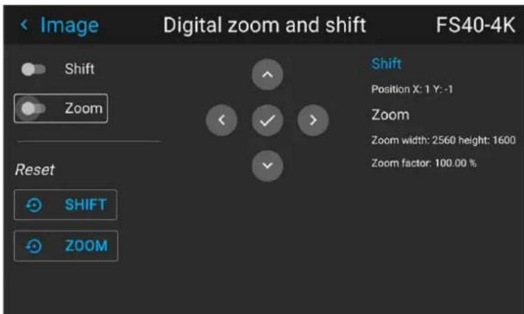
Image 7-1
7.7.1 Digital Zoom
Digital Zoom
This function will zoom the picture digitally. When zooming in, the center of the image will increase in size. This means that the outer part of the picture will be outside the projectors picture frame. When zooming out, the result is that the picture will be smaller than the projectors picture frame. The area outside the rendered picture will then be black.
See the illustrations below. The red lines in the figures represent the DMD outline.
Enter the menu showed above and toggle the Digital zoom switch. Select the slider according to the instructions in the menu and move it to the desired zoom level.
The numbers on the right side of the menu represent the "new" resolution of the picture (assuming that the whole picture should be visible) in pixels. The aspect ratio will not be affected by the zoom function.
This function can also be used in combination with digital shift.

natural_image
Close-up of a koala with visible facial features and open mouth, surrounded by foliage (no text or symbols)Image 7-2 Originally picture, not digitally zoomed

natural_image
Close-up of a koala's face showing its mouth and eyes, with no visible text or symbols.
natural_image
Close-up photo of a koala with its face and open mouth, no visible text or symbolsImage 7-3 Picture digitally zoomed in Image 7-4 Picture digitally zoomed out
7.7.2 Digital Shift
Digital Shift
This function will shift the picture digitally, meaning that the picture will be moved in any direction. As a result, some parts of the picture might be shifted outside the DMD range.
See the illustrations below. The red lines in the figures represent the DMD outline
Enter the menu showed above and toggle the Digital shift switch. Select the slider according to the instructions in the menu and move it to the desired shift level.
The numbers on the right side of the menu represent the movement (shift) of the picture in pixels referred to the "no shift" position. Positive numbers are shift right/down, and negative numbers are shift left/up.
This function can also be used in combination with the Digital zoom function.

natural_image
Close-up of a koala with textured skin and open mouth, no visible text or symbolsImage 7-5 Original Picture, not digitally shifted

natural_image
Close-up photo of a koala interacting with its face, showing its mouth and whisker (no text or symbols visible)
natural_image
Close-up photo of a koala interacting with a dog (no text or symbols visible)Image 7-6 Picture shifted horizontally Image 7-7 Picture shifted vertically
7.8 Advanced image adjustments
7.8.1 P7 Realcolor
Purpose
When blending images from multiple projectors, the perceived color coordinates of each projector can be altered to a desired common level, so that the projected colors are identical over all projectors used.
Alternatively, if you are unfamiliar with how adjusting the Colors to a specific setting, there are also a certain number of presets available, which forces the color output to specific color standards.
The selection of the presets will vary, depending on the projector type, and the color wheel installed.
How to choose one of the P7 presets
- In the main menu, select Image → Advanced → P7 Realcolor.
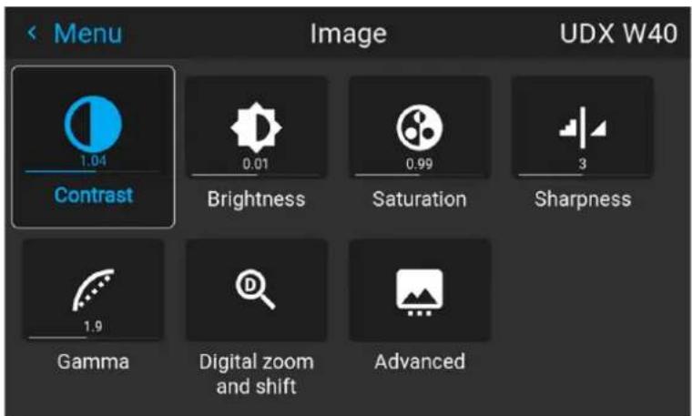
Image 7-1 Image 7-2
The P7 menu is displayed.
-
Choose one of the pre-defined presets:
-
Native: Projector native color settings. Default setting
• EBU: European color standard for broadcasting - SMPTE-C: American color standard for broadcasting.
• Rec. 709: Color standard for high-definition televisions (HDTV).
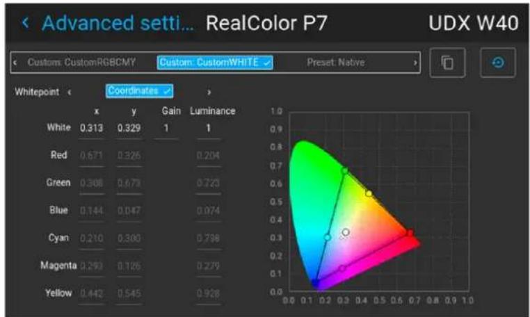
heatmap
| Whitepoint | x | y | Gain | Luminance | |---|---|---|---|---| | White | 0.313 | 0.329 | 1 | 1 | | Red | 0.671 | 0.326 | | 0.204 | | Green | 0.308 | 0.673 | | 0.723 | | Blue | 0.144 | 0.047 | | 0.074 | | Cyan | 0.210 | 0.300 | | 0.798 | | Magenta | 0.293 | 0.126 | | 0.279 | | Yellow | 0.442 | 0.545 | | 0.928 |Image 7-3

Note: When choosing one of the presets, All other options in the P7 menu are disabled.
How to set custom P7 values
- In the main menu, select Image → Advanced → P7 Realcolor.
Image 7-4
The P7 menu is displayed.
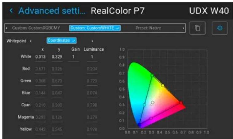
heatmap
| Whitepoint | x | y | Gain | Luminance | | ---------- | ---- | ---- | ---- | --------- | | White | 0.313 | 0.329 | 1 | 1 | | Red | 0.671 | 0.326 | 0.204 | | | Green | 0.308 | 0.673 | 0.723 | | | Blue | 0.144 | 0.647 | 0.074 | | | Cyan | 0.210 | 0.300 | 0.798 | | | Magenta | 0.293 | 0.126 | 0.279 | | | Yellow | 0.442 | 0.545 | 0.928 | |Image 7-5
-
Select the desired Mode. Choose one of the following custom options:
-
Custom RGB: 3-point color configuration.
In RGB mode, the C, M and Y coordinates will be calculated automatically based on the R, G and B coordinates. - Custom RGBCMY: 6-point color configuration (both RGB and CMY).
In RGBCMY mode, each color can be given a specific coordinate within the measured color triangle. -
Custom WHITE: Configure only the White temperature.
-
Define the coordinates for each available color.
Click on a coordinate value and select the current value. Enter the desired value with the numeric keys.

Note: You can only pick coordinates within the measured color triangle.
-
For Custom White, click on White point and choose one of the following:
-
Coordinates: Configure the white point via specific coordinates.
The white point is specified using an x, y coordinate in the CIE 1931 Chart.
• Temperature: Configure the white point via a color temperature slider.
The white point is specified on a Kelvin scale between 3200K and 13000K tracking along the black body curve.

You can reset all coordinates to the default values (to native) by selecting Reset modes to native. Press OK button to reset.
7.8.2 Edit the RealColor presets.
Editing presets
The different presets in the Real Color menu can be edited to obtain an optimal rendering of the picture.
Enter the Menu/Image/Advanced/P7 Realcolor.
menu.
Select the desired preset mode (EBU, Rec709 or SMPTE-C) and select the coordinate within each color component that has to be corrected. Enter the desired value either by:
- Using the keypad to increase /decrease the selected value by the arrow keys.
- Using the remote control: Erase the existing value with the “*” key, and enter the new value by numeric keys.
The values are stored for the preset, until the "Reset" button is enabled, or when a factory reset is performed.
There is also a possibility to store the values in the custom presets.. Press the "Copy preset to custom" button to save.
Image menu
The edited presets can be reset to the original values by enter the Reset button. There is also a possibility to copy the values to the custom preset.
To reset the values in Custom presets, enter the "Reset to native" button when in Custom mode
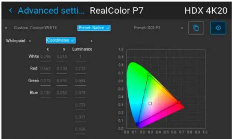
Image 7-6 Preset Native selected
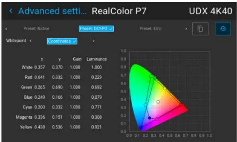
heatmap
| | x | y | Gain | Luminance | | ------ | ----- | ----- | ------ | --------- | | White | 0.357 | 0.370 | 1.000 | 1.000 | | Red | 0.641 | 0.332 | 1.000 | 0.229 | | Green | 0.265 | 0.690 | 1.000 | 0.692 | | Blue | 0.249 | 0.166 | 1.000 | 0.079 | | Cyan | 0.200 | 0.332 | 1.000 | 0.771 | | Magenta| 0.336 | 0.151 | 1.000 | 0.308 | | Yellow | 0.438 | 0.536 | 1.000 | 0.921 |Image 7-7 Editable values
7.8.3 Output resolution 4K
About
With this function, the projector output resolution can be changed between 4K UHD resolution and WQXGA resolution.
Refer to the chapter "Projector source and control connections" regarding use of input sources in 4K mode.
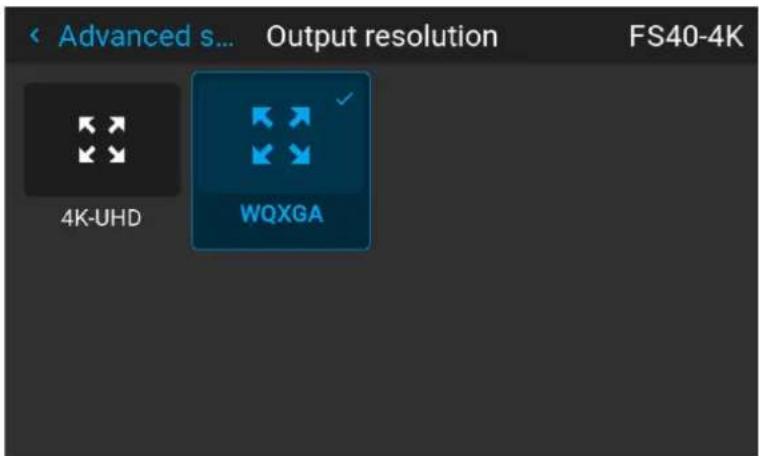
Image 7-8 Output resolution menu
7.8.4 Smear reduction
About
Smear is a phenomenon that typically occur when objects in the picture moves in high speed over the screen. It appears like there is a "tail" behind the object, or a lag in the moving parts of the picture.
In order to avoid this, there has been developed a Smear Reduction Process (SRR), that reduces this perceived rendering. Select the option that give the best result.
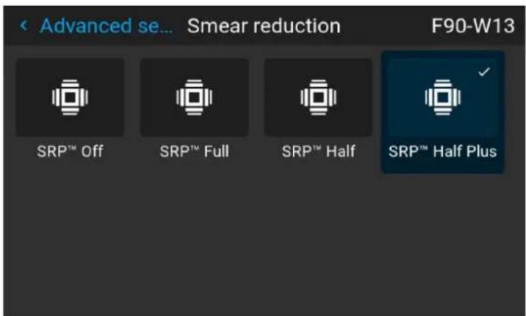
Image 7-9
This menus are only valid for projectors with COLOR colorwheel. For BRIGHT colorwheel, there is no menu choices in the SRP menu, only SRP-Off.
(See tables below).
7.8.5 Brilliantcolor
About
Changes the color rendering, by adding secondary colors. This has the effect of increasing the color intensity, and by that also the perceived light intensity.
Enter the menu, and select the option that give the best result
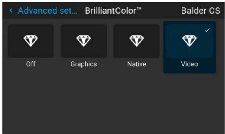
Image 7-10
This menu is only valid for COLOR colorwheel in WQXGA@60Hz mode. For BRIGHT colorwheel, there are only two choices in the menu; Off and Native.
(See table below)
Menu choices of SRP and Brilliant Color matrix with COLOR colorwheel installed.
Valid when COLOR colorwheel is installed.
| Mode SRP Brilliant Color | ||
| WQXGA @60Hz | SRP Off Off | |
| Native | ||
| Video | ||
| SRP Half Off | ||
| Native | ||
| SRP Full Off | ||
| Native | ||
| SRP Half Plus Native | ||
| Off | ||
| BSI (Black Sub Frame Insertion) Native | Off | |
| Video | ||
| Graphics | ||
| SRP Half BSI Native | ||
| Off | ||
| SRP Half Plus BSI | Native | |
| Off | ||
| Video | ||
| WQXGA@120Hz / 4K mode | SRP Off Off | |
| Native | ||
| Video | ||
| Graphics | ||
| SRP Half Off | ||
| Native | ||
| SRP Half Plus | Off | |
| Native | ||
| Video | ||
| 4K @ 60Hz | BSI (Black Sub Frame Insertion) | Native |
| Off | ||
| Video | ||
| Graphics | ||
| SRP Half BSI Native | ||
| Off | ||
| SRP Half Plus BSI Native | ||
| Off | ||
| Video | ||
| SRP Off Off | ||
| Native | ||
| Video | ||
| SRP Half Off | ||
| Native | ||
| SRP Half Plus Native | ||
| Off | ||
Menu Choices
Menu choices of SRP and Brilliant Color matrix with BRIGHT colorwheel installed.
| Mode SRP Brilliant Color | ||
| WQXGA @60Hz | Off | Off |
| Native | ||
| WQXGA@120Hz / 4K mode | Off | Off |
| Native | ||
| 4K @ 60Hz | BSI Native | |
| Off | ||
| SRP Off Native | ||
| Off | ||
Menu choices of SRP and Brilliant Color matrix with VizSim colorwheel installed.
| Mode SRP Brilliant Color | ||
| WQXGA @60Hz | SRP Off Off | |
| Native | ||
| Video | ||
| SRP Half Off | ||
| Native | ||
| Video | ||
| SRP Full Off | ||
| Native | ||
| Video | ||
| SRP Half Plus | Off | |
| Native | ||
| Video | ||
| WQXGA@120Hz | SRP Off Off | Native |
| Video | ||
| SRP Half Off | ||
| Native | ||
| Video | ||
| 4K mode SRP Off Off | ||
| Native | ||
| Video | ||
| SRP Full Off | ||
| Native | ||
| Video | ||
7.8.6 Displaying HDR content— Perceptual Quantizer (PQ)
About PQ
Perceptual Quantizer (PQ) is a non-linear electro-optical transfer function (EOTF) that allows for the display of High Dynamic Range (HDR) content with a luminance level of up to 10 000 cd/m ^2 and can be used with the Rec. 2020 color space.
How to properly display HDR content?
If your provided HDR content has been mastered with PQ (e.g. HDR10 and Dolby Vision), a few changes can be made in order to project the intended mastering on screen. These changes are necessary because HDR content has been mastered specifically for HDR capable displays that are watched in living rooms. These conditions are different from a non-HDR projector and darker cinema-like environments.
The projected HDR content depends on the following factors:
- Mastering luminance: This is content-specific and cannot be changed.
- Screen luminance: Every projection screen has a specific luminance (measured in nits or foot-lambert). Entering this luminance in the projector will adapt the content towards the intended HDR result.
- HDR Boost: A variable "booster" that may amplify or downplay the HDR output.
How to set the PQ?
- In the main menu, select Image / Advanced settings / HDR
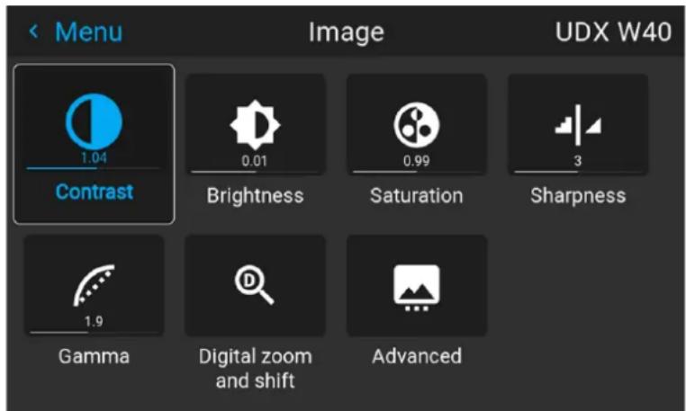
Image 7–11
The HDR menu is displayed.
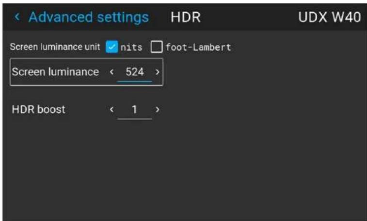
Image 7-12
- Select the desired Unit (nits or foot-lambert).
- Enter the Screen luminance (either in nits or foot-lambert).
- Alter the HDR boost if necessary. You can modify this value to somewhere between 0.8 and 1.2.
7.8.7 HDR Status.
About HDR status
When an active source is HDR, an icon is visible in the status menu.
The HDR icon will also be visible in the "Source signal popup" icon in the lower right corner on the screen.
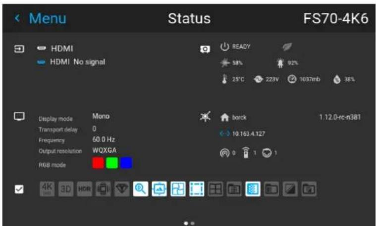
Image 7-13 HDR Icon.
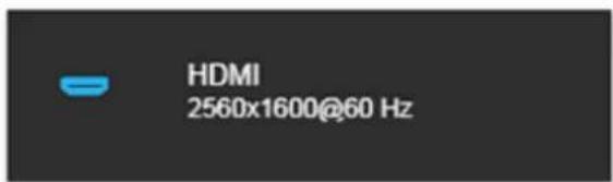
Image 7-14 Source signal popup icon.
7.8.8 Night vision
About
When using e.g. displayport 1 as daylight image input, and displayport 2 as night vision input, this option makes it possible to swap these two channels in the image processing in order to synchronize with the NV goggles.

This function is only available for the FS variants of the projector.
How to swap channels
Select the Menu/ Image / Advanced / Night Vision.
menu
Toggle the Swap channel function on / off by pressing the OK button on the remote control or the keypad.
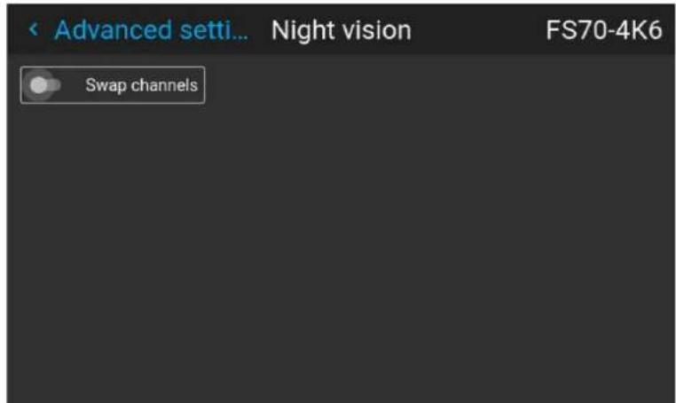
Image 7-15
Installation menu
8
8.1 Lens 108
8.2 Orientation 111
8.3 Scaling modes....112
8.4 Warping 114
8.5 Blending 125
8.6 CLO feature 132
8.7 IR / Night vision functionality....136
8.8 IG pixel shift 137
Menu overview
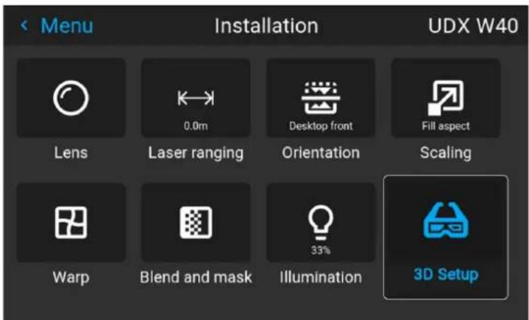
Image 8-1
8.1 Lens
8.1.1 Zoom / Focus
Zoom and focus
Enter the menu Installation / Lens / Zoom Focus
Use either the keypad arrows, or the remote control for this operation.
Use the navigational arrows, up and down, to adjust zoom.
Use the navigational arrows, left and right, to adjust focus.
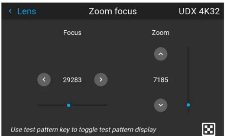
Image 8-1
General
Zoom controls the size of the projected image.
Focus controls the sharpness of the projected image.
Lens zoom and focus adjustments are motorized. You can use the remote control, local keypad, OSD and/or RS-232 commands to adjust the lens zoom and focus positions.

Not all lenses have zoom or iris control. The matrix below shows what controls are available per lens.
| E-N11 | E-N12 | E-N13 | E-N14 | E-N15 | E-N16 | E-N33 | E-N41 | E-N42 | E-N43 | E-N44 | E-N45 | E-N46 | E-N47 | |
| Iris √ | √ √ | √ √ | √ | ✗ √ | √ √ | √ √ | √ √ | √ | ||||||
| Zoom √ | ✗ | √ √ | ✗ √ | ✗ √ | ✗ √ | √ √ | √ √ | ✗ | ||||||
| Focus √ | √ √ | √ √ | √ √ | √ √ | √ √ | √ √ | √ √ | √ |
For best results, lens adjustments should be done in the following order: zoom, focus and then iris (where applicable).
8.1.2 Shift
General
The lenses can be shifted vertically and horizontally to facilitate precise image positioning in single and multiple projector systems. The projector allows for horizontal and vertical shift in both directions. Always place the projector perpendicular to the screen, and use the lens shift to align the picture.
Use the Remote control or the keypad on the Projector to adjust the lens shift mechanism.
Use the left, right, up and down navigational arrows to adjust the lens shift in four directions. This feature moves the picture optically within the shift range of the lens optics.
Press the right key to enable shift, and use the arrow keys on the remote control, or the keypad to move the picture in vertical and horizontal directions.
If not possible to align the projector perpendicular to the screen, due to environment of other, see chapter "Warp - 4 Corners adjustment", page 117
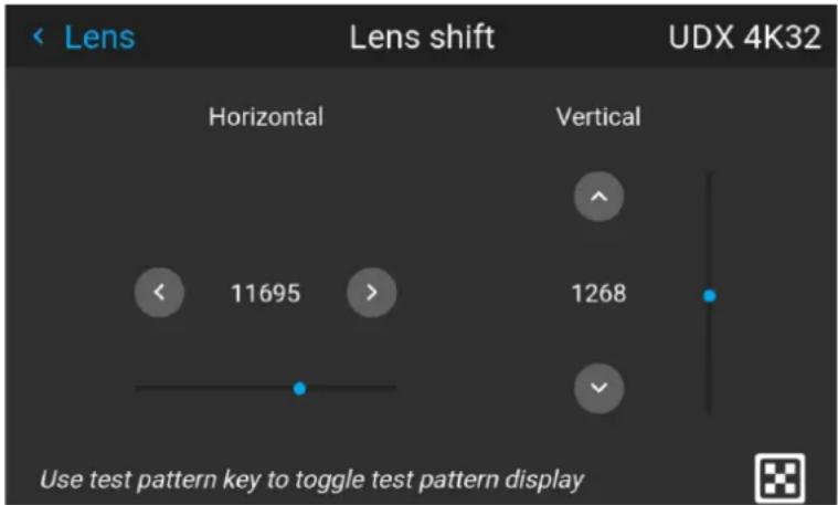
Image 8-2

When EN 68 lens is installed in the projector, there are some limitations in the lens shift range, in order to avoid damage to the lens.
This limitation will be identified as an reduction in the output light from the projector when the shift position exceeds the defined range. The output light will then be reduced to 20% of max.
8.1.3 Shift to center
From remote control
This function adjust the lens position to the mechanical mid position.
Enter the Menu/installation/Lens/Shift to center
menu.
Confirm with the √ button on the remote control, and the "Lens shift to center position?" pop up windows shows up.
Move the highlighted rectangle to "OK", and confirm with the √ key.

When EN68 lens is installed:
Due to restrictions in light output for the EN 68 lens, the mid position for this lens will not be the mechanical mid position, but the mid position of the area where max light output is allowed.
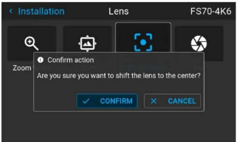
Image 8-3
From the keypad
Press the Lens button on the keypad. A menu picture as shown below shows up.
Press the √ button for 3 seconds.
8.1.4 Iris
General
Iris controls the contrast and focus depth of the image. Decreasing the iris will increase contrast and image depth, at the same time as it decreases brightness.
The number below the keys in the menu indicate the degree of engagement of the iris. 0 = iris full open, and increasing number (1 — 98) indicates that the iris is positioned somewhere between the open and closed position according to the number indicated.
Iris control is, as for the zoom and focus control, motorized, and is operated by the remote control or local keypad.

Iris is only available for units with COLOR type colorwheel.
To enter Iris control, enter the Menu/Installation/Lens /Iris
menu.
Use the arrow keys to adjust Iris until preferred rendering is obtained.
Use the arrow keys to adjust Iris until preferred rendering is obtained. The numeric value in the menu indicates the degree of opening of the iris.
Value = 0, full opening. (No iris activated).
Increased numeric value indicates decreasing in the iris opening. (Iris activated).
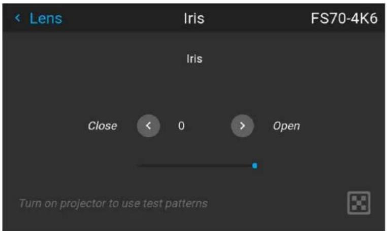
Image 8-4
8.2 Orientation
About
Menu/Installation / Orientation
Rotate the image on the imaging device depending on the physical installatin of the unit.
There are four installationoptions, as illustrated below:
- Front/table
- Front/ceiling
- Rear/table
- Rear/ceiling
- Auto front
- Auto rear
Default: Table Front.
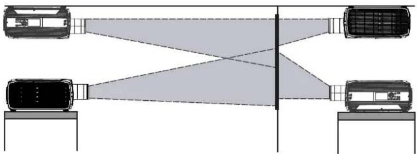
flowchart
graph TD
    A["Vehicle 1"] --> B["Coverage Area"]
    C["Vehicle 2"] --> B
    D["Vehicle 3"] --> B
    B --> E["Output"]
    style A fill:#f9f,stroke:#333
    style C fill:#f9f,stroke:#333
    style D fill:#f9f,stroke:#333
Image 8-5
How to set the correct orientation
Select Orientation from the menu
The orientation menu is displayed

Image 8-6 Orientation Menu
Use the arrow keys to select the Mounting and Projection positions, and press OK button to activate.
The Auto front / rear will detect the orientation of the projector (desktop / ceiling), and is just an shortcut to the front / rear setup.
8.3 Scaling modes
General

For the modes Fill Screen and Stretch, the screen size must be defined, see chapter "Warping Screen Size".
The purpose of the scaling mode is to adapt the image on the screen in an optimal way, based on the desired rendering. The examples below shows a screen format of 2,35:1, and a DMD format 16:10. (WQXGA).
The scaling mode function has four different presets:
- Fill aspect
• 1:1 - Fill Screen
- Stretch.
The illustrations below shows the resolution for WQXGA, and a screen aspect ratio of 2,35:1 (Cinemascope format. But the principle is the same also for other resolutions and screen sizes.(4K, WUXGA / 16:10, 16:9..)
Mode Fill aspect
This mode utilizes as much as possible of the native size of the DMD, and keeps the aspect ratio.
Input signal (Source): 4 : 3
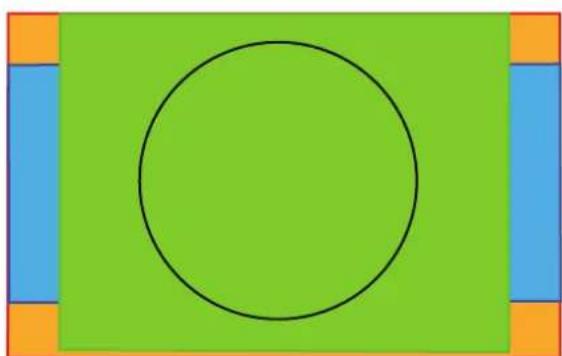
natural_image
Simple geometric diagram with a black circle centered on a green rectangle, flanked by blue rectangles and orange corner markers (no text or symbols)DMD Capacity: 1,6:1 (2560 x 1600 pixels)
Screen: 2,35 : 1 (Cinemascope)
Image 8-7
1:1
This mode is an exact rendering of the source signal, pixel by pixel
Input signal (Source): 4:3
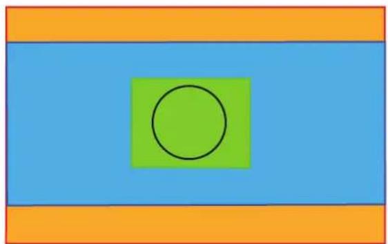
natural_image
Simple geometric diagram with a green circle centered within a blue rectangle, surrounded by orange horizontal bands (no text or symbols)DMD Capacity: 1,6 : 1 (2560 x 1600 pixels)
Screen: 2,35 : 1 (Cinemascope)
Image 8-8
Fill Screen
This mode utilizes the defined screen size, and keeps the aspect ratio.
Input signal (Source): 4:3
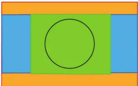
natural_image
Simple geometric diagram with a black circle centered within a green rectangle, surrounded by blue and orange rectangular sections (no text or symbols)DMD Capacity: 1,6 : 1 (2560 x 1600 pixels)
Screen: 2,35 : 1 (Cinemascope)
Image 8-9
Stretch
This mode stretch the rendered picture to utilizes the defined screen size. The rendered picture will then be stretched / distorted compared with the source signal.
Input signal (Source): 4:3
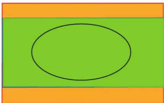
natural_image
Simple geometric diagram with a black oval inside a green rectangle, surrounded by orange horizontal stripes (no text or symbols)DMD Capacity: 1,6 : 1 (2560 x 1600pixels)
Screen: 2,35 : 1 (Cinemascope)
Image 8-10
How to enter.
Enter the Menu/Installation/Scaling
menu.
Select the desired mode and press OK button on the remote control or keypad.
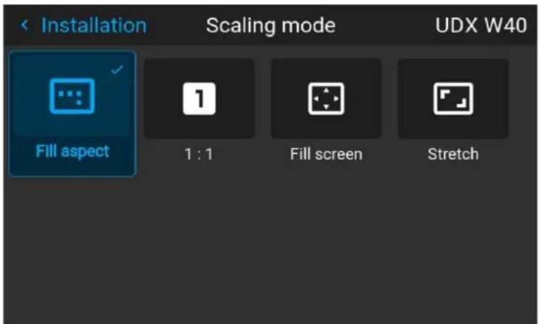
Image 8-11
8.4 Warping
8.4.1 About warping
About
Image warping is the process of digitally manipulating an image to compensate for the distortion of the screen, typically by non perpendicular alignment of the projector versus the screen. The image will then typically occur as shown in Image 8-1.
While an image can be transformed in various ways, pure warping doesn't affect the colors.
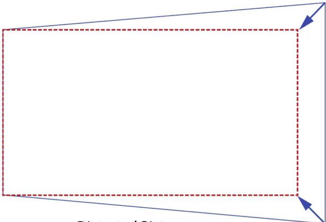
natural_image
Pure geometric diagram with a rectangle and dashed lines, no text or symbols presentDistorted Picture
Ideal Picture
Image 8-1
8.4.2 Warping - On/Off
About warping on/off
By toggling between on and off the warping functionality can be enabled or disabled.
How to toggle
- In the main menu, select Installation → Warp.
Image 8-2 Installation menu, warp
The Warp menu is displayed.
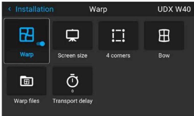
Image 8-3 Example of the Warp menu
- In the Warp menu, click Warp to toggle between On and Off.
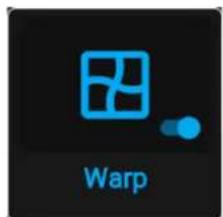
Image 8-4 Image 8-5
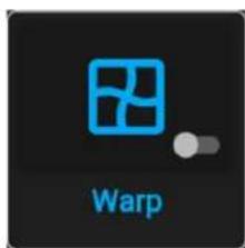
8.4.3 Warping - Screen size
About (Warp) Screen Size adjustment
If the used screen aspect ratio is different than the projector aspect ratio, e.g. source is 16:9 and projector is 16:10, then black bars will be projected. In the example case a black bar on top and bottom of the image will be projected. The warp area contains not only the image information but also the black bars. If we want to position e.g. the active left top corner exactly on the screen using 4 corner warp, then it is very hard to do that as we are moving the black left top corner and we do not have control over the exact position of image left to corner. By moving the outline of the warp screen size to the active image information, the corner points of the warp area are now exactly on the corner points of the active image information and makes warping much easier.
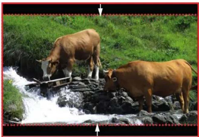
natural_image
Two brown cows standing on a rocky stream with water flowing, surrounded by green grass (no text or symbols visible)Image 8-6 Warp outline example
How to adjust the image?
- In the main menu, select Installation/Warp/Screensize.
The Screen Size menu is displayed.
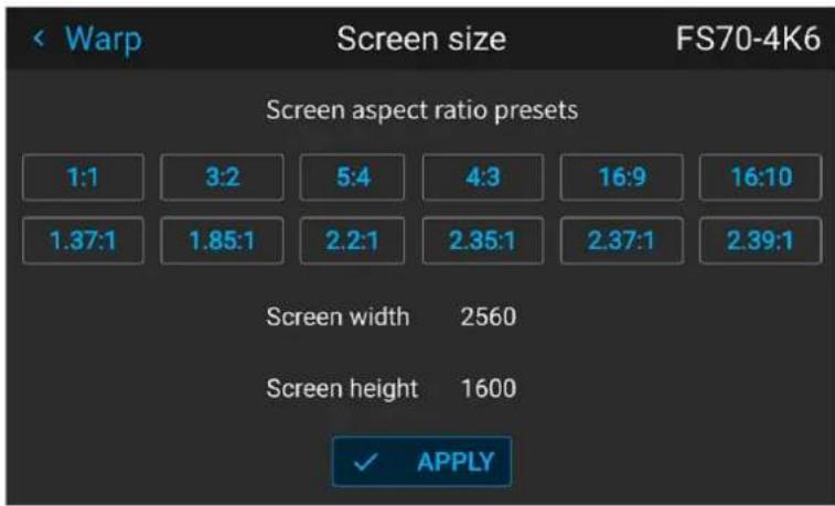
Image 8-7
- Select the pre defined aspect ratio that suits the aspect ratio of the screen.
- Set the screen size width and height to match the measurement of the screen.

Note: It is only the ratio between the width and height that is used, so the values may be entered as the screen aspect ratio or actual measurement in cm, inches or any other unit.

Tip: A red border will be projected along with the current image. The border is a visual tool, showing the result of the adjusted outline.
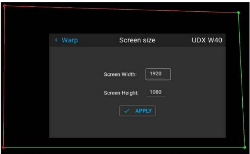
Image 8-8

Tip: The value can also be entered by the numeric keys on the remote control. Press * to delete existing numbers, and enter the new value by the numeric keys.
- Click Apply.
8.4.4 Warp - 4 Corners adjustment
About 4 Corners adjustment
Basically, this type of warping adjusts each of the four image corners in the X and Y direction, if you have a typical trapezoid picture of the screen as shown below.
To have a successful Warp correction, the size of the screen must be entered. See "Warping – Screen size", page 116
Some examples of pictures when the projector axis is not perpendicular to the screen.:
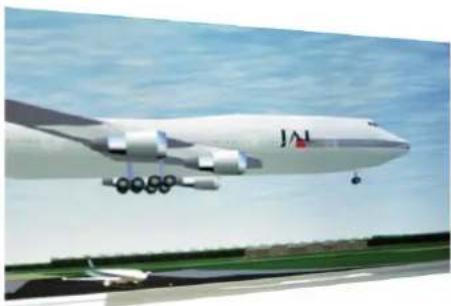
natural_image
Exterior view of a large commercial airplane (JAL) flying over an airport runway under a clear sky, with no visible text or symbols on the aircraft body.Image 8-9
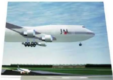
natural_image
Exterior view of a large Airbus IAC aircraft in flight with landing gear deployed, against a clear sky (no visible text or symbols)How to adjust the image.
- From the warp menu, select the menu Installation/Warp/4 Corners.
- Select and enter the Helper lines slider. A yellow frame will be visible.
- To enable the 4 Corners Warping, Set the Warp slider to the right position. (Select and enter).
- Enable the corner that must be warped (Select and enter). If need for warping several corners, select and adjust the corners one by one.
- Adjust the value by the arrow keys. The X value is adjusted by the left/right arrows on the remote control, and the Y vale is adjusted by the up/down arrow in the remote control. The value represent the movement of the X and Y coordinates for each corner. When the warping is complete, exit the menu by using the "Back" button.
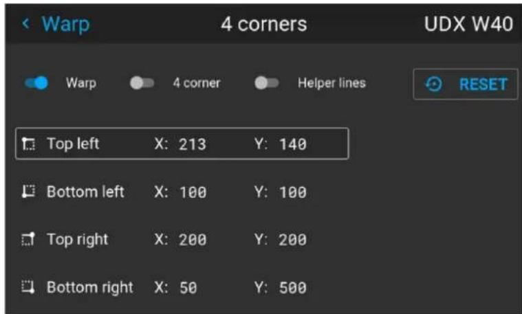
Image 8-10
- If the picture still has a trapezoid shape, warp is not enabled. Select the Installation / Warp menu, and press enter. The slider moves to the right, and the warp status changes to "On".
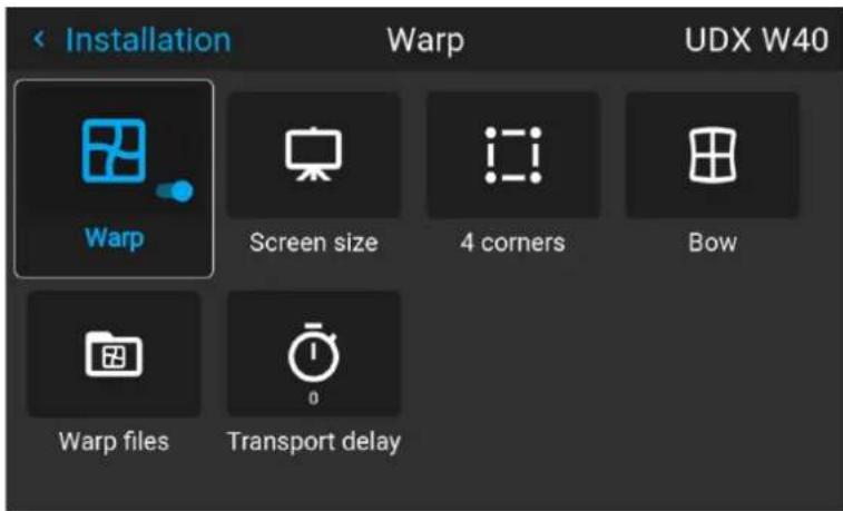
Image 8-11
8.4.5 Warping - Bow
About bow adjustment
A bow distortion can be adjusted so that a normal image is displayed. Positive adjustments angles introduce more outside bow distortion. Negative adjustments introduce more inside bow distortion.
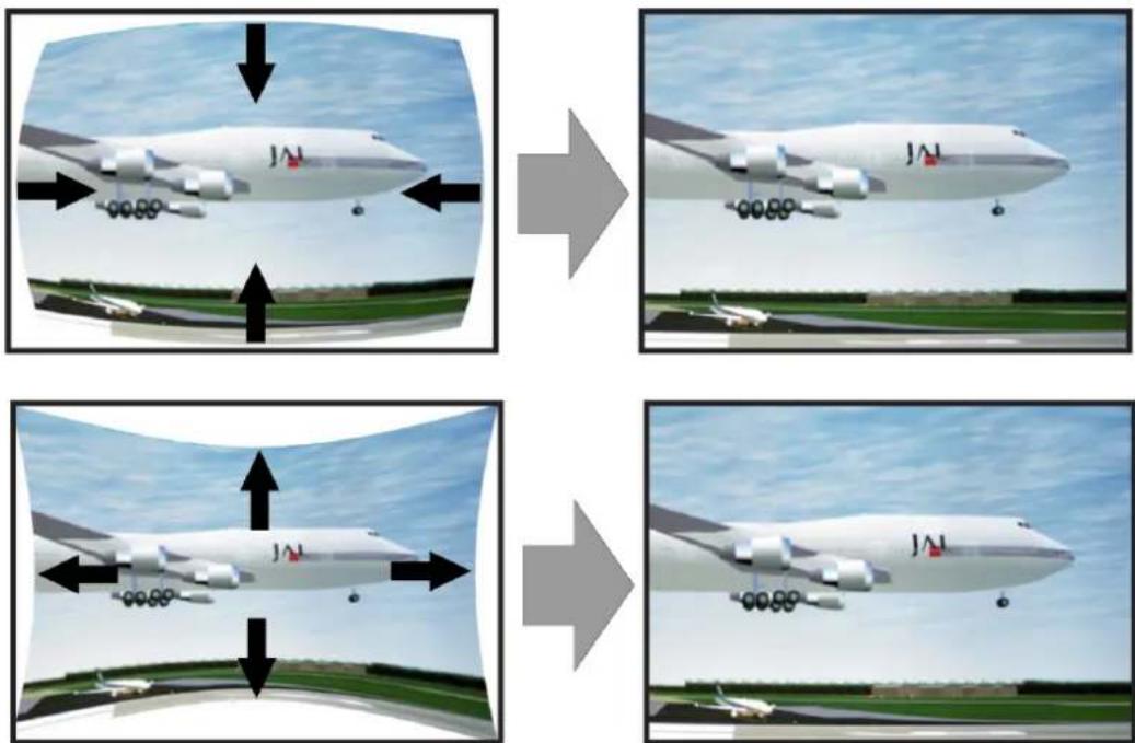
Image 8–12 Bow distortion
Symmetric bow correction
- In the main menu, select Installation/Warp.
Image 8-13 Installation menu, Warp
- In the Warp menu, select Bow.
Image 8-14 Warp menu, Bow
A check symbol at the bottom right corner indicates that the bow function is activated.
When the bow menu is selected, a grid will occur in the screen picture in order to visualize the adjustments performed.
- To enable Bow correction, make sure the Bow slider is set to On.
The slider is enabled when set to the right and when it is highlighted blue.
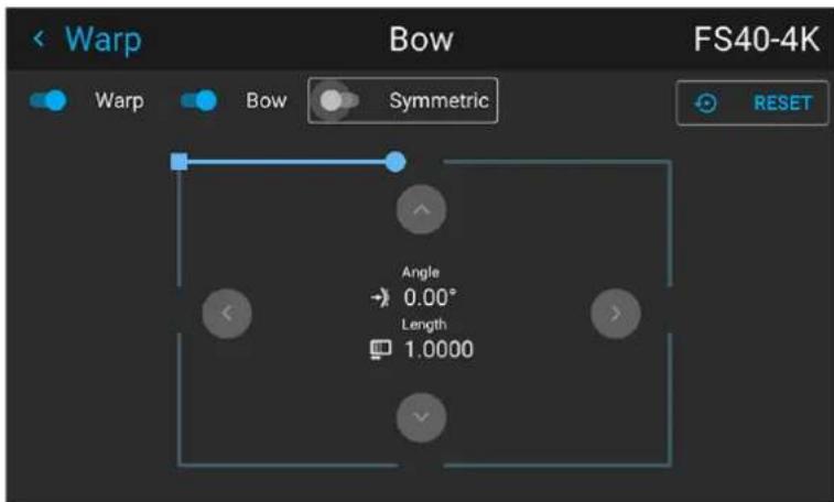
Image 8-15 Symmetric Bow correction.
- To enable a symmetric adjustment, make sure the Symmetric slider is set to On.
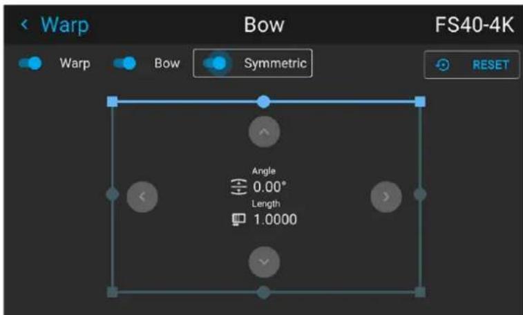
Image 8-16
The slider is enabled when set to the right and when it is colored blue.
- Select the side of the picture to be bow corrected, confirm by pressing enter, and use the arrow keys to adjust the angle and linearity (length) of the vectors.
The angle is adjusted by the up and down arrows on the remote control, and the linearity is adjusted by the left and right arrows.
The correction will occur symmetrically on each side of the center of the highlighted side.
When corrected with the values in the image above, the picture will occur as shown below.
Repeat this step for all sides of the picture that has to be corrected.
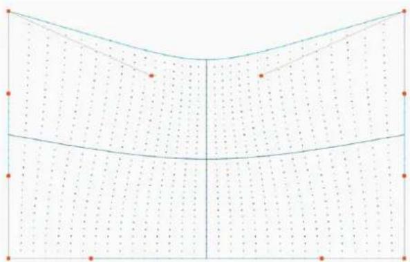
natural_image
Pure geometric diagram with grid lines and dots, no text or symbols presentImage 8-17 Symmetric bow corection
Non symmetric bow correction
-
Enter the Bow menu, and disable the symmetric slider.
-
There are now two vectors on each side of the picture that can be adjusted individually. Select each of them, and adjust angle and linearity (length) individually to obtain the correct correction.
The angle is adjusted by the up and down arrows on the remote control, and the linearity is adjusted by the left and right arrows
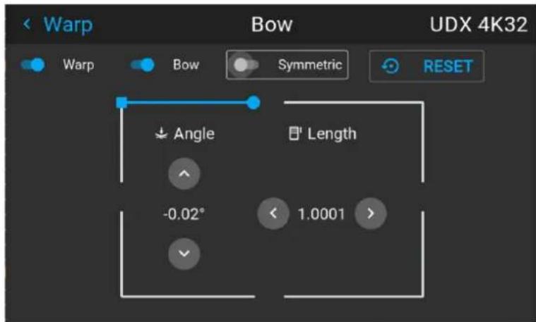
Image 8-18 Left vector of the upper side of the picture.
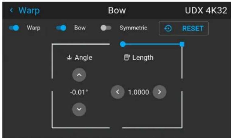
Image 8-19 Right vector of the upper side of the picture.
- When corrected with values in the illustrations above, the picture will occur as shown below. Observe that the upper side of the picture now has an asymmetric correction.
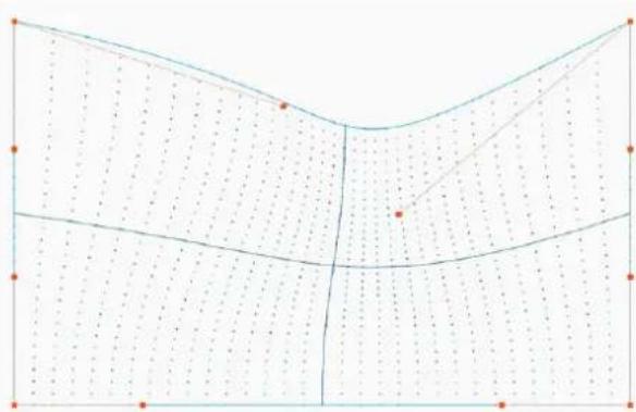
natural_image
Pure geometric diagram with grid lines and dots, no text or symbols presentImage 8-20 Asymmetric bow correction
- Repeat the step for each side of the picture that must be corrected.
Definition of angle and linearity (length) in the bow warp procedure
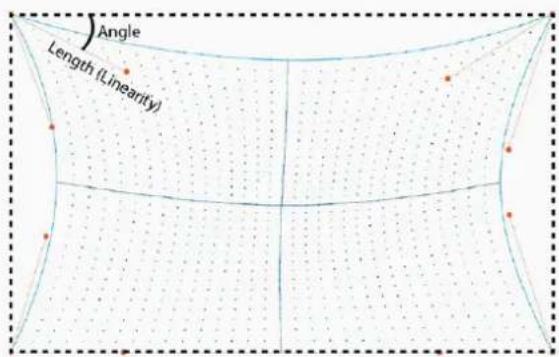
Image 8-21

To reset the bow adjustments, select Reset and press the OK button.
8.4.6 Warping - Warp files
About custom Warp Files
Next to setting your specific warp configuration in the GUI, you can also upload or download a custom warp grid in XML format to/from the projector. This is a time-saving option when multiple projectors need an identical Warp configuration.
To upload or download warp files you can use Projector Toolset or Prospector tool to upload/download the warp grid in the format of an XML file. Alternatively, you can contact the "file endpoint" directly via the curl program or some other tool that supports http upload.
For more information on uploading/downloading Warp files using the Projector Toolset, refer to the Projector Toolset user manual.
For more information on uploading/downloading Warp files using curl or other tools that supports HTTP upload, refer to the Pulse API Reference Guide.

When uploading a warp file that is too big, or with warp parameters outside the limits of the projector, some irregularities can occur. It will show up in two ways:
1: No warp enabled, picture still unwarped.
2: Distortions and artifacts in the edges of the picture.
There will be no error messages or warnings in the display when this occurs. The above mentioned symptoms is the only indication of this case.
How to activate an uploaded Warp grid?
- In the main menu, select Installation → Warp.
Image 8-22 Installation menu, Warp
- In the Warp menu, select Warp files.
Image 8-23 Warp menu, Warp files
The Warp Files menu is displayed.
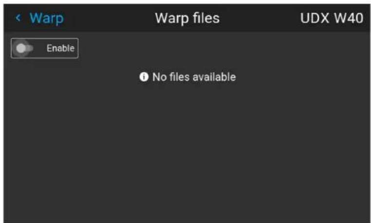
Image 8-24 Example of the Warp files menu
- Make sure the Enable slider is set to right.
- Select the desired warp file.
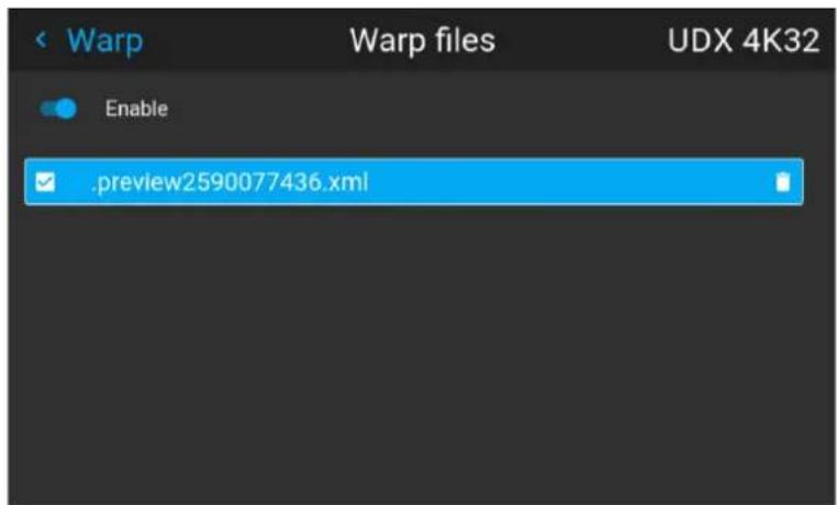
Image 8-25 Example of the Warp files menu
8.4.7 Warping - Latency control in a multi projector setup

Transport latency
The added delay in the image processing chain. The value is the number of lines relative to the output resolution.

Latency
The total time from the first pixel is coming in on an input source, until the first light representing that pixel is visible on the screen. This includes the transport delay. The value is normally given in milliseconds.
Functional description
Every projector in a multi-projector setup will have a different latency. This latency depends on the amount of warp and on the frequency of the projected image. In order to have no visible difference in the overall projected image, the user needs to be able to control the latency of each projector.
The latency value can be read out in the status menu for each individual projector.
How to configure transport delay?
- Read out and note the latency of each projector in the multi-projector setup. You can find this latency under Transport delay in the status menu for each projector.
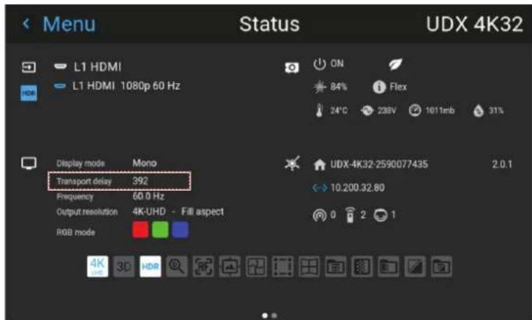
Image 8-26 Example of the Transport delay in the status menu
-
Identify the projector with the longest delay.
-
For each projector in the setup, select Installation → Warp in the main menu.
Image 8-27 Installation menu, Warp
- In the Warp menu, select Transport Delay.
Image 8-28 Warp menu, Transport delay
The Transport delay menu is displayed.
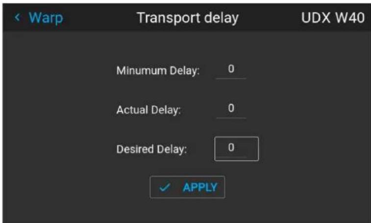
Image 8-29 Example of the Transport delay menu
- Enter the value either by the arrow keys (one step at a time) or directly by the numeric keys on the remote control.
- Click Apply to confirm the value.
- Repeat this process for every projector in the setup.
8.5 Blending
8.5.1 Introduction to blend functions
When to use blend functions
When two projectors are used together to make one picture on the screen, the blend function must be activated. This blend function ensures a seamless transition of the images between the two projectors.
The principle is that the light intensity in the blend zone from each projector will be adjusted individually, so that the rendering on the screen are perceived as from one projector.
The blend function can be enabled for both pictures over/under, and pictures side by side.
The blend will not be affected by the projector's warp.
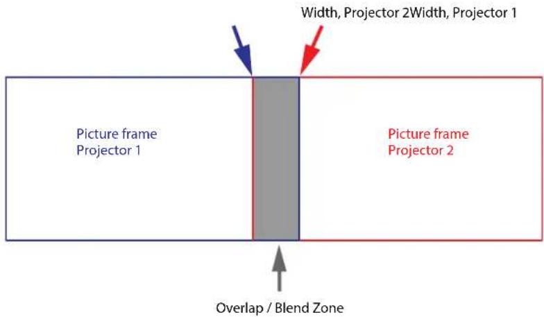
Image 8-1
The Mask adjustments.
The offset adjustments are used to cut the image on each side. Normally used to hide parts of the picture that shall not be shown on the screen. An example can be: If the source is a pc, you may want to hide the menu bar at the bottom of the screen.
8.5.2 Set up the system
How to set up the system
In this chapter, the setup procedure for the projectors is explained, but a setup procedure must also be performed for the picture source.

In order to obtain a satisfying result for the Blend function, the overlap / Blend zone are recommended to be at least 10% of the picture width.
The basic principle is that the overlap setup in the source shall correspond with the blend width setup for the projector. That means that if the overlap zone for the source is set to 500 pixels, the width of the blend zone the projector also must be set to 500 pixels.
First step is to align the image from the projectors as accurate as possible in a mechanical way, meaning without any optical corrections. At the same time, establish an overlap in the pictures between the two screens.
Then adjust the remaining irregularities by using the shift and warp features in the projectors to obtain the last fine tuning of the alignment.
Setup the source to a blend which corresponds with the preset overlap on the screen. There are different ways to do this, depending on the source. Refer to the source unit's manual for this issue.
Adjust the Blend for the projectors as described below.
8.5.3 Blend mask setup procedure
Blend mask introduction
The blend mask function blends out an area on the outer edges in the picture. This function is applicable when e.g. icons in the toolbar in an image from a pc is to be projected.
The blend mask area will be defined in the blend mask setup process.
Blend mask adjustment procedure
- Enter the menu Installation/Blend/Blend mask
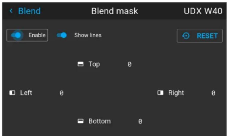
Image 8-2
- By the arrow keys, place the display cursor on respectively the "Enable" zone and the "Show Lines" zone and activate them by pressing enter.
- Use the arrow keys to move the cursor to the position that must be masked. and press enter.
- Adjust the mask area (width) by pressing the arrow keys on the remote control. By pressing the key arrow constantly, the blend value will increase rapidly. The numeric value of the width is shown on both the LCD screen and the OSD. (The number entered represent the blend width expressed in number of pixels).
-
Use the enter key to move the cursor to the next position that has to be masked.
-
Adjust the value by using the arrow keys. (See note below).
- Repeat step 4 and 5 to adjust the rest of the blending zones.
- Exit the menu by using the exit button on the remote control.
8.5.4 Basic blend setup procedure
Basic blend adjustment procedure
Entering the Basic blend Adjustment from the Menu/Installation//Blend and mask/Basic blend menu, either by the remote control, or the keypad on the projector.
The “Enable” button enables/disables the blend function. The “Show Lines” enables alignment lines on the screen, in order to visualize the overlap/blend zone.
Use the up/down/left/right arrow key on the remote control or key pad to navigate in the menu.
Basic blend introduction
The basic blend function introduces an gradual transition of the light intensity between the edge of the picture and the line defined in the basic blend setup process.
When a blend mask is introduced, the gradient will start from the defined edge of the blend mask.
Basic blend adjustment procedure. Side by side configuration.
- In the menu select Installation/Blend/Basic blend. The Basic blend menu is displayed.
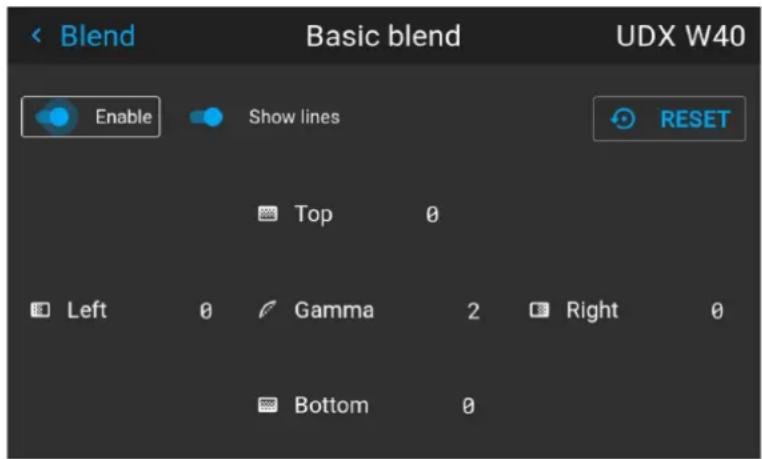
Image 8-3
- Starting with the left picture: By the arrow keys, place the display cursor on respectively the "Enable" zone and the "Show Lines" zone and activate them by pressing enter.
- Use the arrow keys to move the cursor to the position that must be blended. and press enter.
- Adjust the width value by using the arrow keys (See note below), one step at a time. By pressing the key arrow constantly, the blend value will increase rapidly. The numeric value of the width is shown on both the LCD screen and the OSD. (The number entered represent the blend width expressed in number of pixels).
- Use the enter key to move the cursor to the next position that has to be blended.
- Adjust the value by using the arrow keys. (See note below).
- Repeat step 4 and 5 to adjust the rest of the blending zones.
- Exit the menu by using the exit button on the remote control.

For horizontal blending, use the left/right arrow keys to adjust. For vertical blending, use the up/down arrow keys to adjust.
Adjustment procedure in over / under configuration.
For Blend adjustments in over / under configuration, the procedure is the same as for side by side, but use the Top and Bottom height instead, and perform a similar procedure.
Use the numeric keys instead of the arrow key to set the values.
Instead of adjusting the lines by the arrow keys, the value can also be typed directly using the numeric keys on the remote control.
To remove or undo the entered numbers, use the * key on the remote control.
8.5.5 Black level setup procedure
Black level introduction
The Purpose of the black level adjustment is to adjust the black levels in the non overlapped areas with the black level in the overlapped areas (Blend Zone).
This is a necessary function, due to the fact that the black level will be brighter in the blend zones, since multiple projectors will add light in these zones.
The width of the black level area shall ideally be slightly larger than the width of the blend zone in order to also compensate for the “sea of mirrors” phenomenon.
The figure below shows how this occurs in a side by side configuration without any correction of the black level.
Picture Left Picture RightBlend Zone
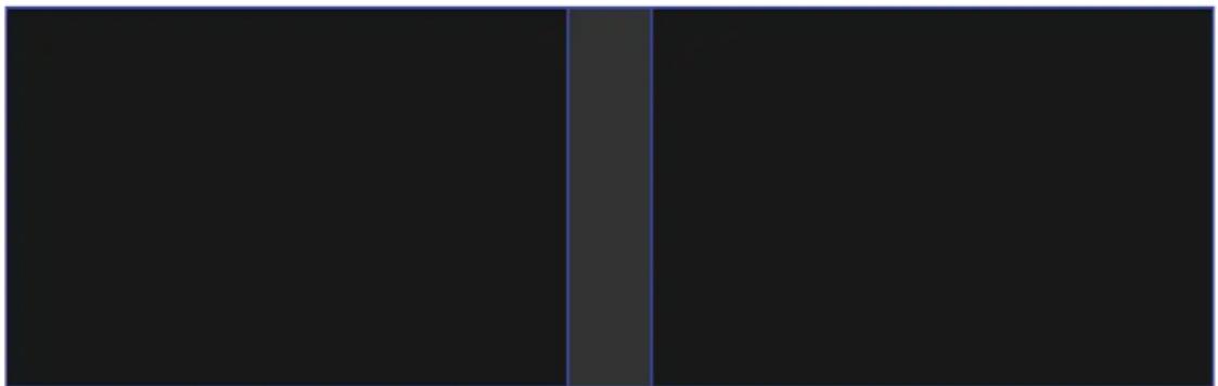
natural_image
Two vertical black bars separated by a gray vertical line, no text or symbols present.Image 8-4
Black level adjustment procedure
- Select the menu Installation/Blend and mask/Black level.
- Enable the "Black level" and "Show lines" buttons. A line that indicates the blend zones will be visible on the screen when "Show lines" is enabled.
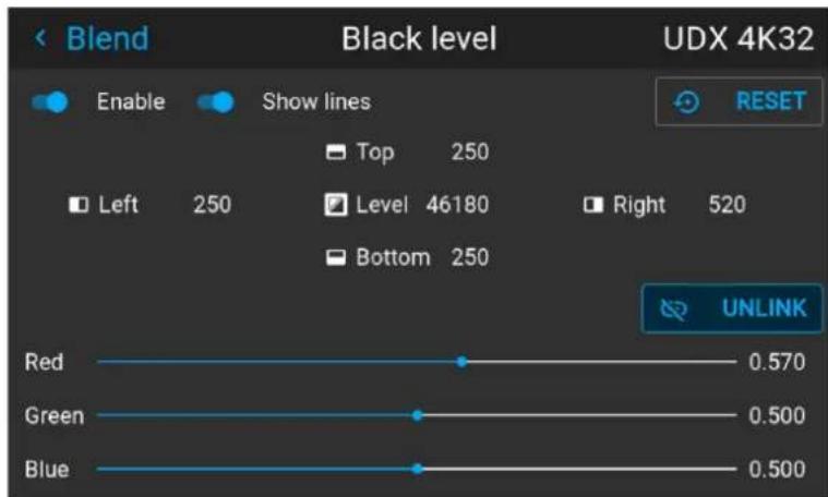
Image 8-5
-
Move the cursor to the side where the overlapped area occurs. (Left/right/top/bottom.) For the left projector, this will typically be the right side in the menu as an example.
-
Press enter, and adjust the value with the arrow keys. The icon shown below will appear on the OSD when the side is selected. The value shall typically be the same as for the basic blend line. (Same numeric value).
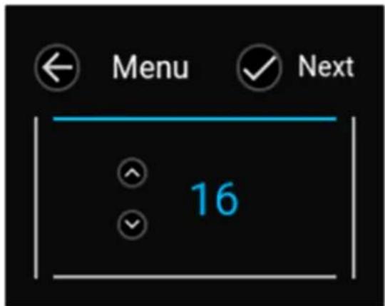
Image 8-6
-
When the value is ok, press enter on the remote control, and the icon on the OSD will jump to the next side. Adjust, and repeat for all sides.
-
When all sides are completed, press "Back" button on the remote control.
-
Move the cursor to "Level", press enter and adjust this level until the black level equals the level in the blend zone.

Note: In addition to the black level itself, it is also possible to adjust the color saturation in order to align the projectors in the layout, see procedure "Adjusting the color level" below.
-
Repeat the same procedure for the other projector,
-
Disable the "Show lines" when the Black level adjustment is completed.
8.5.6 Color level adjustment procedure
Color level introduction
When using several projectors in a complete setup, there will always be a slightly difference in the color saturation between the projectors. This is not visible
The purpose of black level correction is to ensure a uniform black level in multi projector setups. Even when two projectors are of the same type, different projectors will output slightly different colors for black due to minor variations in their optical components. So if the projected image of the projectors overlap, there will be 3
different black levels: one for the zone where only the picture of the left projector (zone 1), one for the Blend zone (zone 2), and one for the zone where there is only the picture of the right projector (zone 3).
Picture Left Picture RightBlend Zone
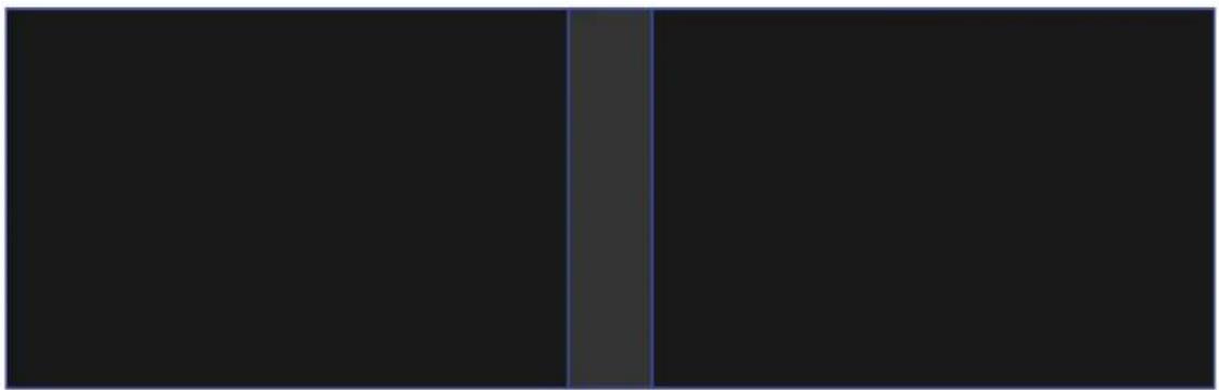
natural_image
Pure black rectangle with a vertical gray stripe on the left side (no text or symbols)Image 8-7
How to perform an RGB adjustment
- In the main menu, select Installation / Blend and mask / Black Level for all projectors in the setup. The Black level menu is displayed, containing the sliders for color adjustment.
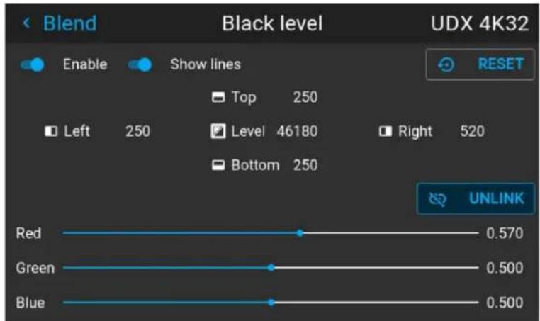
line
| Color | Value | |-------|-------| | Red | 0.570 | | Green | 0.500 | | Blue | 0.500 |Image 8–8
- Use "black" test picture for the projectors.
- Observe manually the color saturation from each projector unit, and identify the difference.
- If one projector, as an example, has more red in the test picture, select the red slider in the black level menu for this projector and adjust the slider with the arrow keys to obtain a similarity in the rendering.
- Repeat for every projector and color until the desired result is achieved on screen.
8.5.7 Black level files
Black Level Files introduction
Next to setting your specific Black Level Adjustment in the GUI, you can also upload or download a custom Black Level adjustment file in png, jpeg or tiff format to/from the projector.
To upload or download Black Level masks you can use the Prospector tool. Alternatively, you can contact the "file endpoint" directly via the curl program or some other tool that supports http upload.
For more information on uploading/downloading Black Level files using the Prospector, refer to the Prospector user manual.
For more information on uploading/downloading Black Level files using curl or other tools that supports HTTP upload, refer to the Pulse API Reference Guide.
How to activate an uploaded Black Level adjustment file?
- In the main menu, select Installation / Blend and mask / Black level files
Image 8–9 Blend menu, Black Level Files
The Black Level Files menu is displayed. Files will be listed in this window
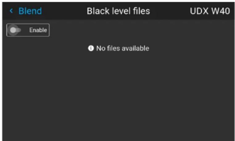
Image 8–10
- If any custom Black Level adjustment files are available, select the desired file.
- Click on the on/off button on top to activate the selected Black Level adjustment file.
8.5.8 Blend files
Blend files introduction
Next to setting your specific Blending configuration in the GUI, you can also upload or download a custom Blend configuration file in png, jpg or tiff format to/from the projector. This is a timesaving option when multiple projectors need an identical blending configuration.
To upload or download Blend masks you can use the Prospector tool.
Alternatively, you can contact the "file endpoint" directly via the curl program or some other tool that supports http upload.
For more information on uploading/downloading Blend files using the Prospector, refer to the Prospector user manual.
For more information on uploading/downloading Blend files using curl or other tools that supports HTTP upload, refer to the Pulse API Reference Guide.
How to activate an uploaded Blend configuration file?
- In the main menu, select Installation / Blend and mask / Blend files
Image 8-11 Blend menu, Blend Files
The Blend Files menu is displayed.
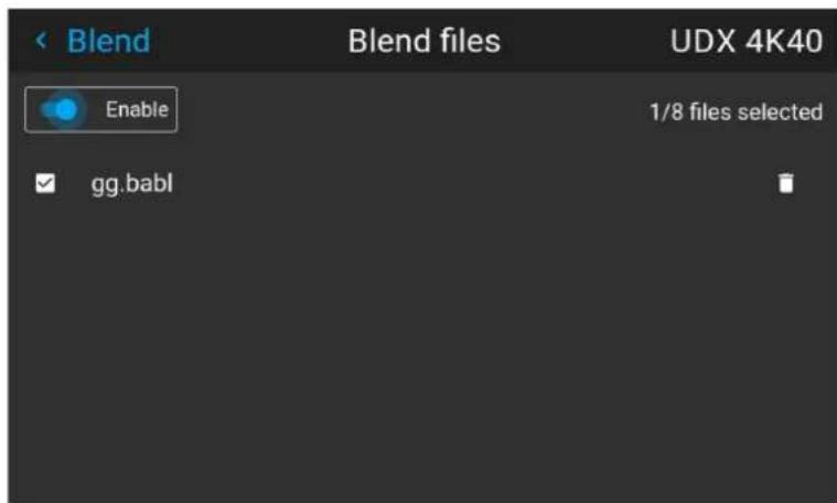
Image 8-12
- If any custom Blend files are available, select the desired file.
- Click on the on/off button on top to activate the selected Blend file.
8.5.9 Advanced blend
Description
The Advanced Blend Function is intended for blending in complex shapes in multiprojector installations.
Due to the complexity, a separate manual has been prepared for this subject, and can only be performed by an authorized installer. There is no user interface for this function.
8.6 CLO feature
8.6.1 Introduction
Introduction
The CLO (Constant Light Output) is a Barco Pulse software feature for maintaining a stable light output from the projector over time, by automatically adjusting the light source. The CLO feature utilizes a light sensor placed internally in the projectors light path.
8.6.2 Placement of the light sensor
Placement of the light sensor
The light sensor is placed after the illumination iris. This means that the CLO feature will be impacted by the illumination iris position. The lens iris, due to its placement in the lens outside the projector, does not impact the light sensor, and thus neither the CLO. Changing the lens iris will have an impact on the light output of the projector for which the CLO cannot compensate.
8.6.3 Using the CLO features
8.6.3.1 CLO feature in the OSD, Prospector and API
CLO feature in the OSD
Navigate to Installation — Illumination
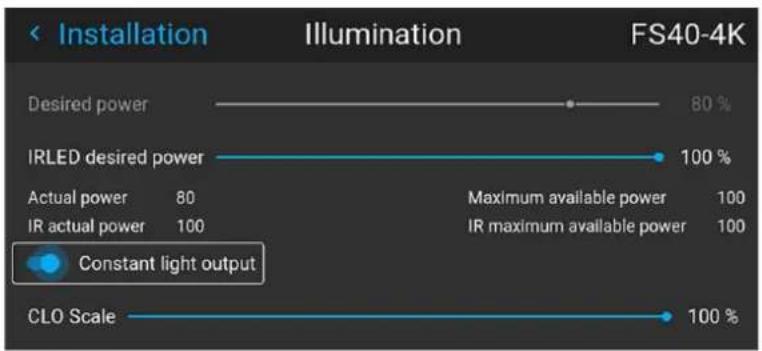
bar
| Category | Value | | -------------------- | ----- | | Desired power | 80% | | IRLED desired power | 100% | | Actual power | 80 | | IR actual power | 100 | | Maximum available power | 100 | | IR maximum available power | 100 | | Constant light output | - | | CLO Scale | 100% |Image 8-1
CLO feature from Prospector
Navigate to Settings — Illumination

Image 8-2
CLO feature from API
- illumination.clo.engage
- Enables the CLO and creates a new set-point for the CLO
- illumination.clo.enable
- Enable the CLO: "value": true
- Disable the CLO: "value":false
- This command enables the CLO while keeping the previous set-point for the CLO
8.6.3.2 Notifications applicable for the CLO feature
Info
• L8000b Illumination clo mode {0}
- Modes: Enabled or Disabled
• L8000c Illumination CLO target set to 0
- Value refers to the set-point of the CLO
Warning
• L8000a Illumination clo unable to maintain the desired light output
- Explanation: The light source power is at its maximum and can no longer maintain the desired light output
• L8000d Illumination cli light measuring failed
- Explanation: The CLO failed while trying to measure the light on the light sensor, either when enabling the CLO or during CLO operation
8.6.3.3 Example for using the CLO feature for maintaining brightness over time Maintaining the brightness
- Adjust lightsource power to desired setting, e.g. 80%
- Enable the CLO
• The projector will maintain the brightness at 80%
The CLO adjusts the power to the light source to maintain the light output over time. As there is a degradation over time in both optical components and light source, the time frame the CLO can maintain the light output is dependent on how much initial headroom is available. I.e. if the power is set to 90%, the initial headroom will be more quickly spent by the degradation and the time frame for which the CLO can keep the desired brightness will be lower than for e.g. starting at 80%. See example below.
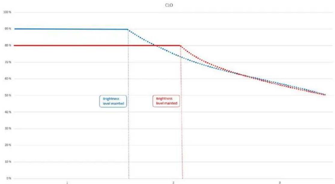
line
| x | brightness level maintained | brightness level mainted | | --- | --- | --- | | 1 | 50% | 80% | | 2 | 50% | 80% | | 3 | 50% | 50% |Image 8-3 The time scale is only used as an example and does not represent real-life data.

The time scale is only used as an example and does not represent real-life data.
8.6.4 CLO scale
8.6.4.1 CLO scale
CLO scale
The CLO scale feature enables linear dimming. The light source power of the projector is not linear, so adjusting it to e.g. 50% could result in a different light output than the desired 50% of the initial light output. The lack of linearity could result in it deviating up to 5% from the desired target. The CLO scale ensures that the dimming scale is linear, meaning that the desired output level of the light source will be the same as the setting in the projector.
Having the light source power dimming linear also enables it to be used to set the same power value to multiple projectors.
The same prerequisites apply for this feature regarding the degradation of the light source and the initial set-point chosen for the light source power.
The CLO scale can be set and / or monitored using the property:
- illumination.clo.scale
CLO, typical user cases
To linearly dim the projectors and / or using the same dim value on all projectors in a multi-channel configuration when e.g. going from a day scene to a night scene.
8.6.4.2 Example: CLO scale with one projector
Example: CLO scale with one projector
• Light output: 5000lm.
- Adjust the light output from the projector to 80% .
The projector now has a maximum light output of 4000 lm
- Enable CLO scale
• Light output at different CLO scale settings
- 100: 4000 lm
- 75: 3750 lm
- 50: 2000 lm
8.6.4.3 Example: CLO scale with 3 projectors
Example: CLO with 3 projectors
- Light output:
- Projector 1: 5000 lm
- Projector 2: 4900 lm
- Projector 3: 4800 lm
- Match the light output of the projectors using the standard light source power feature.
- Using 80% of Projector 3 in this example, all projectors now have a light output of 3840 lm
- Enable CLO.
- The CLO scale can now be used to set the light output to the same value on all projectors as the CLO has been enabled on the same actual light output from all 3 projectors.
- Note that the CLO scale value must be sent separately to all 3 projectors.
8.6.5 CLO stable signal
Signal stability
The light sensor, providing the CLO feature with data, requires time to stabilize when changing the light source power in large steps using the CLO scale, e. g. from 80% to 20% when going from a day scene to a night scene. This could cause an issue if the projector is used for training before the light output has stabilized.
When the CLO is enabled, a signal called has stabilized will be available. The signal tells the user if the CLO is stable or is still in a state of change, trying to obtain a stable light output.
The CLO has stabilized signal only works when actively changing the CLO scale.
Rationale:
The CLO will change the light source power in small steps given the criteria: "average of measurements the last 10 seconds shall not differ more than 0.75% from the set-point". This to maintain the desired light output. From a user perspective no interaction has been made with the projector, so a change to the hasstabilized signal in this case would not make sense.
The functionality presented in a Given-When-Then format.
| Given When | Then | |
| CLO is enabled No adjustment to CLO scale is done | hasstabilized = true, even when internal adjustment is needed to obtain the current setpoint for the CLO | |
| CLO is enabled CLO | scale value is being changed has stabilized = false, while adjusting CLO scale | |
| CLO is enabled CLO | scale value has been changed | hasstabilized = true, when the CLO output has stabilized |
The hasstabilized signal can be monitored using the property:
• illumination.clo.hasstabilized
- "result": true
- "result": false
- Requires power user access
8.6.6 EWMA
EWMA
This is the average of the measurements on the light sensor, used for controlling the CLO feature.
EWMA can be monitored using the property:
- illumination.clo.ewma
- "result": a value, without a defined unit
8.6.7 Setpoint
Setpoint
This feature enables the user to set the desired value directly. As no max value is given Barco recommends using the CLO scale if different output power settings are needed when using the CLO.
The setpoint can be set and/or monitored using the property:
- illumination.clo.setpoint
8.6.8 CLO (Light sensor) calibration

This process is only implemented for the F70 and F90 series projectors, valid from SW 2.2.
Light sensor calibration
The CLO is calibrated from the factory and re-calibration is not expected to be necessary. In the unlikely event that the CLO would need to be re-calibrated, please log in as a Power user in Prospector and go to Service→Light sensor calibration and follow the steps to calibrate the CLO.
8.7 IR / Night vision functionality
About
IR / Night Vision functionality is only available for the FS variant of the projector..
In combination with Night Vision Goggles (NVG), this will give a realistic rendering of the environment. This will visualize in a realistic way, night time, dusk and dawn, and limited visibility scenarios.
The IR light source has a wavelength of 740nm
How to enable IR/Night Vision.
Enter the Menu/ Installation / Illumination menu. This menu shows two sliders; one for the LED Desired power (daylight), and one for the IR LED Desired power (Night Vision). The sliders are scaled from zero – 100% power.
Image 8-1
Select the Desired power slider, and move the slider to the left by the arrow keys to nearly 0% to reduce the light intensity. (Daylight visibility). By this, the IR LED will be dominant, and the image on the screen will be visible with the Night Vision Goggles. Put on the goggles, and adjust the IR LED slider to obtain an optimal night vision rendering.
By mixing the intensity (power) of both the Desired power and the IR LED, it is also possible to simulate other visibility scenarios, such as evening / early night vision.
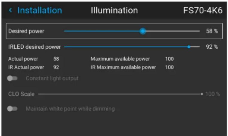
bar
| Lighting Type | Power Level | Value | | ----------------------- | ----------- | ----- | | Desired power | - | 58 % | | IRLED desired power | - | 92 % | | Constant light output | CLO Scale | 100 % |Image 8-2
8.8 IG pixel shift
About
All sub-menus, except from the IG Pixel shift, are described in other topics in this manual, where they more naturally belong.
8.8.1 IG pixel shift
General
IG pixelshift is a feature where the Image Generator can process the image in two channels.
This two input channels have different positions of the pixelshift module. Channel 1 is displayed with module position 1, and channel 2 is displayed with position 2. The result is a 4K rendering of the displayed image.
Max frequency pr channel is 60 Hz.
Only DVI or Displayport inputs on the projector can be used for this purpose.
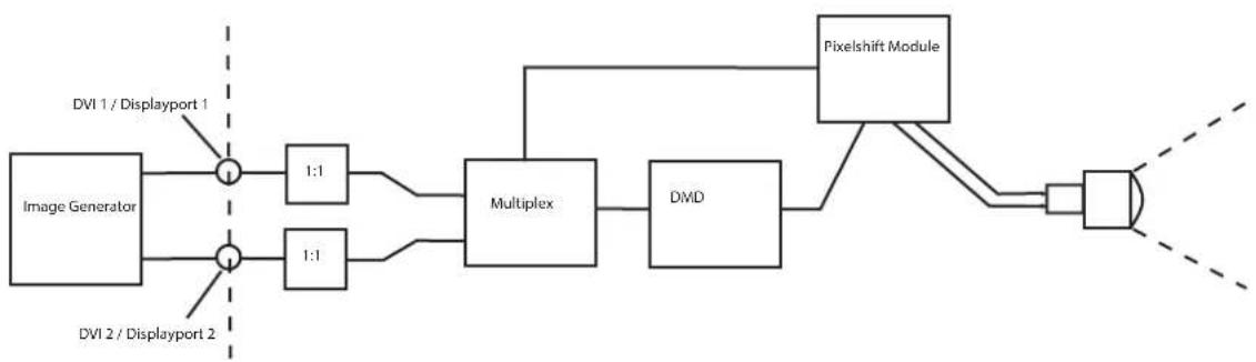
flowchart
graph LR
    A["Image Generator"] --> B["1:1"]
    C["DVI 1 / Displayport 1"] --> B
    D["DVI 2 / Displayport 2"] --> E["1:1"]
    B --> F["Multiplex"]
    E --> F
    F --> G["DMD"]
    G --> H["Pixelshift Module"]
    H --> I["Output"]
Image 8-1 IG Pixelshift. Principle of operation.
Preparations
Perform the necessary setup of the external image source. (Image Generator). Connect to DVI 1/2 or Displayport 1/2.
Enable IG pixel shift
- Enter the menu Installation/ 3D setup
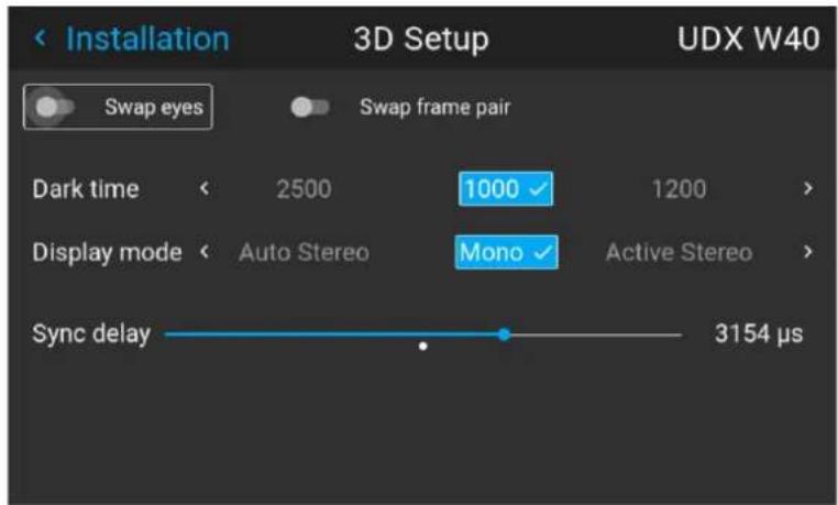
Image 8-2 Display setup Menu
- Use the up / down arrow keys on the remote control to move the cursor to the "Display mode" position.
- Use the left/right arrow key to scroll to IG pixelshift.
- Select by pressing enter.
Status menu
When IG pixelshift is enabled, it will be visible in the Status Menu. (Scroll down a bit to see it), and also in the LCD Information display.
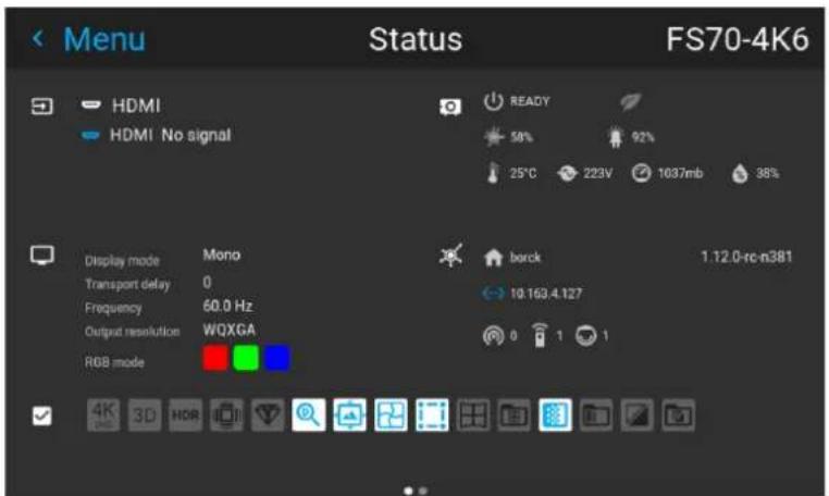
Image 8-3 LCD Information Display.
8.8.2 IG Pixelshift Night Vision
General
In addition to IG pixelshift for daytime environment, the IG pixelshift Night Vision (NV) also includes the functionality for running the pixel shift module when one of the input channels are used for IR content visible through NV goggles.
This also includes a function of swapping visible light / IR light between the two inputs. This switch is default set to IR channel being DVI1/DP1 and visible light being DVI2/DP2 as it is today. This can be useful to swap those two due to the fact that the input DVI1/DP1 has a lower latency than the DVI2/DP2.
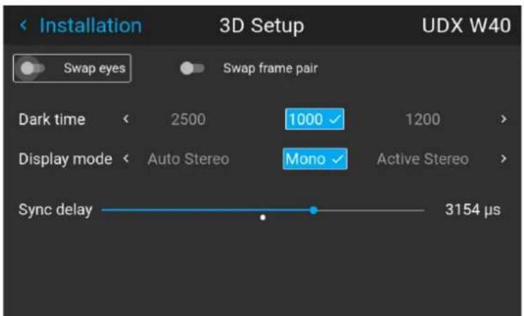
Image 8-4
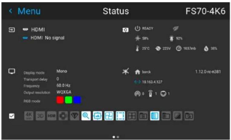
Image 8-5
8.8.3 AutoStereo (3D) Setup
Enabling 3D mode
See chapter "3D", page 167 for 3D mode setup
GUI - Profiles
9
9.1 Profiles introduction 142
9.2 Profiles setup parameters.... 142
9.3 Saving settings to a new profile.... 143
9.4 Deleting a projector profile....145
9.1 Profiles introduction
About Profiles
The profile function makes it possible to store different profiles / projector setups for different use cases, and quickly recall them when needed. This means that it is not necessary to enter a lot of different menus to adjust the projector setup for specific recurring use cases. Due to the limited nature of this function and to avoid terminology confusion with more complex macro's, these are not called "macro's", but "profiles".
A few examples of different user cases are:
- Building temporary gaming setups in bright auditorium-level environment, versus a darker "gaming room" or "cave".
- Playing content from an old DVD versus playing the latest release from an HDR-coded Blu-Ray.
- A rental projector that can be rented out for business presentations, concerts and other events that have different but recurring forms of content.
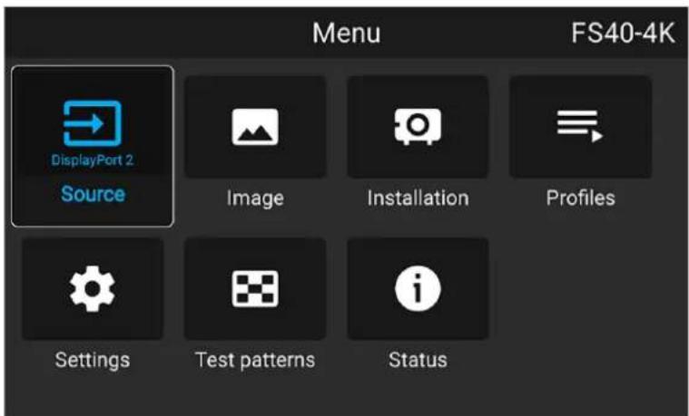
Image 9-1
9.2 Profiles setup parameters
Available profile settings
| Profile domain name | Settings saved |
| Illumination | ·Illumination power for each source·Light sensor enabled / disabled·Light sensor set point |
| Source Active source selection & EDID | |
| Image | ·Contrast·Brightness·Saturation·Sharpness·Gamma·Used gamma type·Digital zoom (width / height / factor + enabled/disabled)·Digital shift (x / y + enabled / disabled)·Output resolution |
| Display (3D settings) | ·3D Display mode used·Swap eyes on / off·Swap frame pair on / off·Dark time and sync delay values |
| RealcolorTM | ·Brilliant Color mode (if available)P7 desired valuesP7 measured values |
| Warp | Warp status enabled / disabledScreen sizeWarp file selected (if available)Transport delayNote: Bow and 4 corners warp cannot be saved. |
| Blend | Blend mask enabled / disabledAll Masks (top / bottom / left / right) and heights (top / bottom / left / right)Blend files enabled / disabled (if available)Blend file selected (if available) |
| Black level | Black level file enabled / disabledBlack Level file selected (if available)Basic black level enabled / disabledBlack level settings (top / bottom / left / right)RGB gain values (Red, Green and Blue values) |
| PQ (HDR) | Screen luminance (unit and value)HDR Boost valueDynaBlack mode |
| Installation | Lens parameters (lens zoom, focus, shift and iris (if available))Orientation (mounting & projection)Scaling modePosition of motorized frame (if used).Shutter status (open or closed). |
| Cooling3 | Selected Cooling mode |
9.3 Saving settings to a new profile
How to save the current projector settings?
- Adjust the necessary projector set up values for the actual user case as described in the specific topics in this manual.
- Enter the menu Profiles
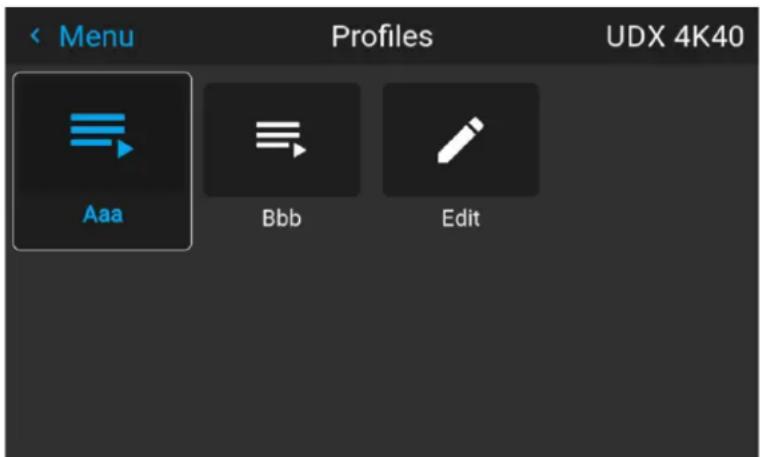
Image 9-2
3. Select the Edit button
Image 9-3
The Profile edit menu shows up.
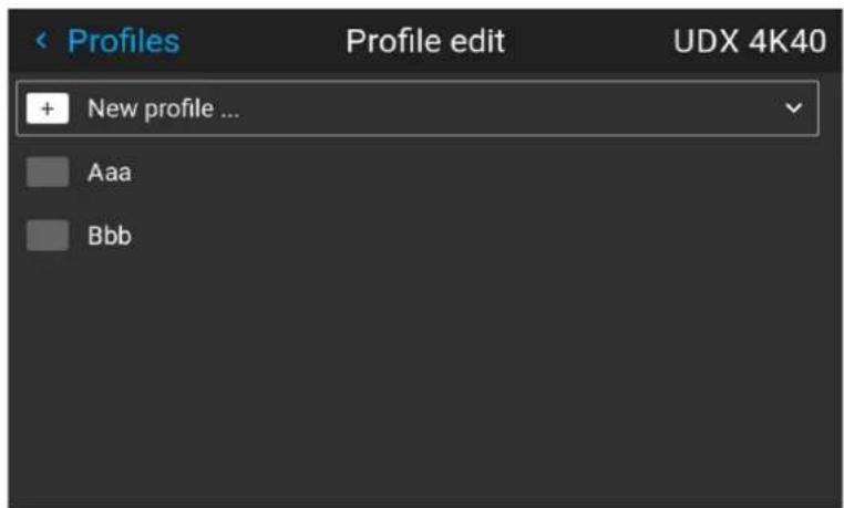
Image 9-4
- Select New profile
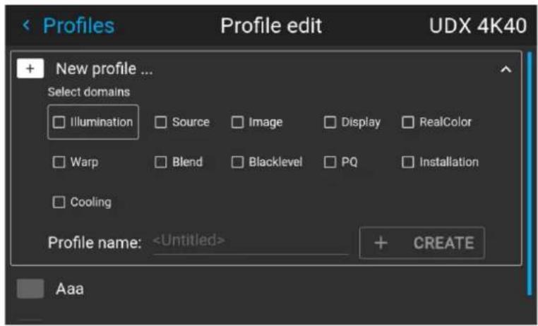
Image 9-5
-
Enter a suitable name for this profile via the pop up keyboard (arrow keys and OK (√) to select). End the name entry by selecting the "return" key on the pop up keyboard.
-
Select the "Assign to preset slot". A drop down menu will show up, select the preferred value.

Note: The function "Assign to preset slot" enables a shortcut to the actual profile from the remote control. If assigned preset slot are set to 1, this profile can be recalled by pressing the key MACRO and then 01 on the remote control. It is not a requirement to use this function, just an option.

Note: The maximum number of profile presets is 30.
- Select the domains in the menu that shall be stored in the profile.
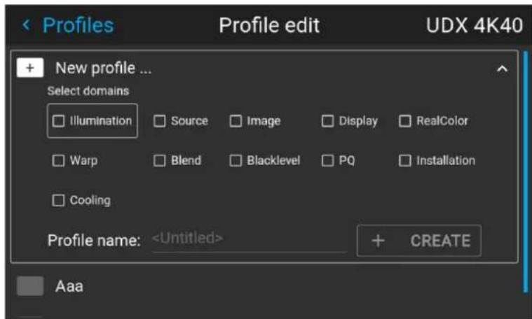
Image 9-6 Select domains
-
Select "Profile name". A keyboard will show up, and enter a proper name for the profile.
-
Select "create" and confirm by the OK button.
The new profile is now created and saved.
- Repeat step 1 to 6 for creating of more profiles.
Recall a profile.
- Enter the Menu/ Profile
The stored profiles will be visible in the menu. Select the actual profile.
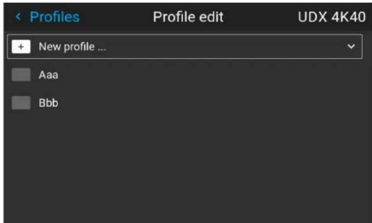
Image 9-7
or
Select the numeric shortcut from the remote control.
9.4 Deleting a projector profile
How to delete a profile
- In the main menu, select Profiles → Edit.
Image 9-8 Profiles menu, edit
The edit menu is displayed.
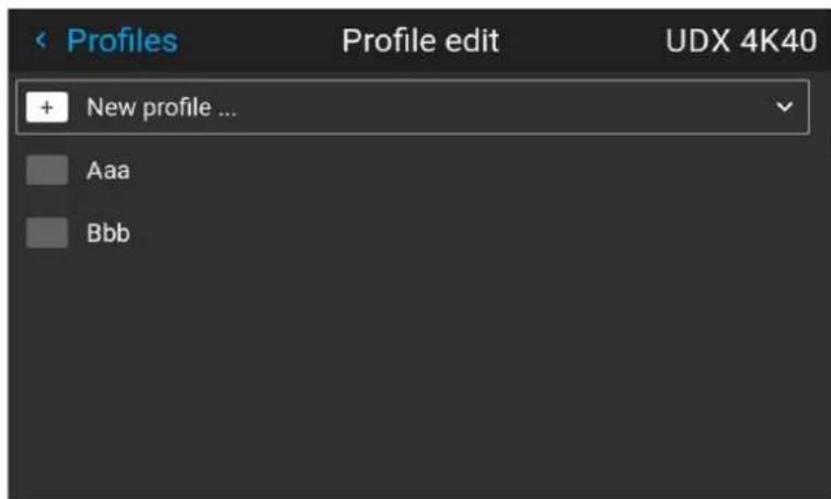
Image 9-9 Profile edit menu
- Select the undesired projector profile and confirm to expand it.
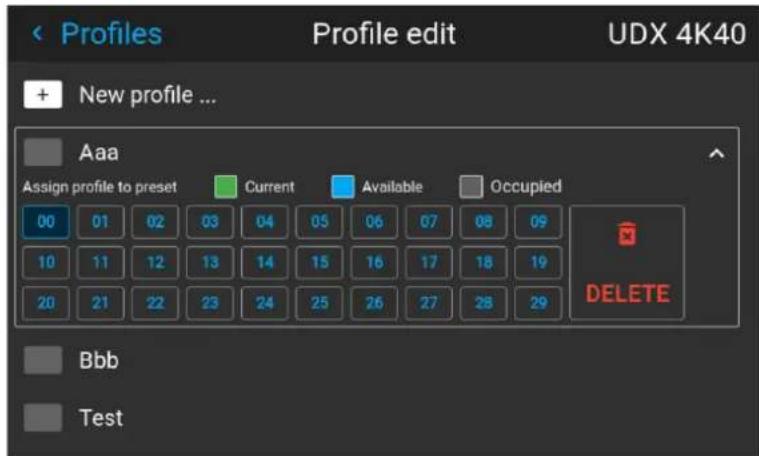
Image 9-10 Example of a projector profile with available preset slots
- Use the arrow keys to select Delete and confirm. confirm the delete action.
System settings menu
10
10.1 Communication 148
10.2 Remote control.... 148
10.3 Host name - custom projector name setup.... 151
10.4 DMX....151
10.5 Trigger 153
10.6 Language 153
10.7 Themes 154
10.8 Units 154
10.9 Backlight 155
10.10 ECO mode 155
10.11 Power settings....156
10.12 Lens features 156
10.13 24/7 Mode....157
10.14 Maintenance 157
10.15 Lens calibration 158
10.16 Reset.... 159
10.17 Controlling the backlight of the LCD Display.... 161
Menu overview
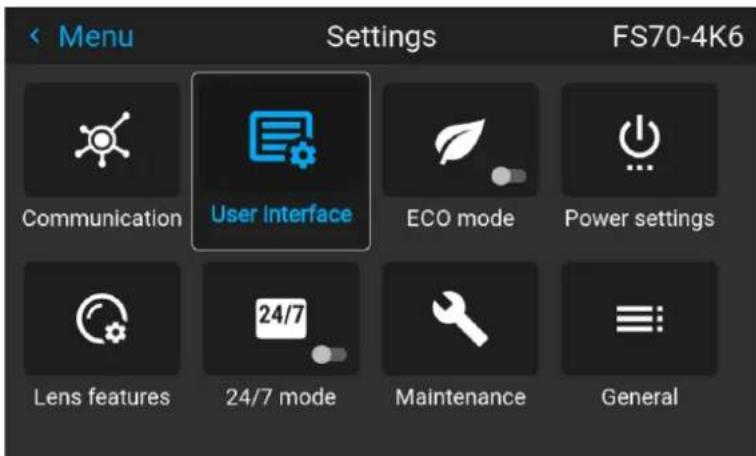
Image 10-1
10.1 Communication
About
Settings / Communication / LAN
Network connection is required to communicate with the projector via LAN or Internet.
Current Ethernet communication information is given, and can be edited in this menu.
Default mode for Ethernet communications are: Automatic ON / IP Version 4 DHCP mode.
| Setting Description | |
| Automatic | |
| ON DHCP enabled | |
| OFF Static | |
| IP version 4 | |
| Static mode Set address, subnet mask and default gateway according to network specification. | |
| DHCP mode Assigned IP address, subnet mask and gateway. | |
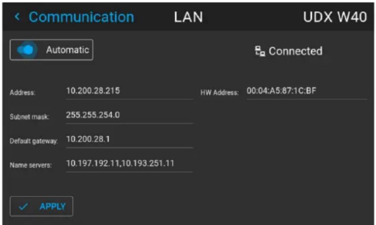
Image 10-2
Manually set up the IP adress
Go to the menu Settings / Communication / LAN
Enable the Auto zone on the display and press enter. The Auto zone will change to "Manual".
Scroll down, and modify the desired fields. When in the desired fields, press “Enter” to enable the virtual keyboard, enter the desired values, and press “Enter” again to confirm the change.
10.2 Remote control
10.2.1 Broadcast address
About broadcast address
Broadcast address is a common address that can be set on the projector. That can be "0" or "1". The default broadcast address is '0'.
Any command coming from an RCU programmed with that common address will be executed.
How to the broadcast address
- In the main menu, select Settings → Communication → Remote control.
Image 10-1 Communication menu, Remote Control
The Remote control menu is displayed.
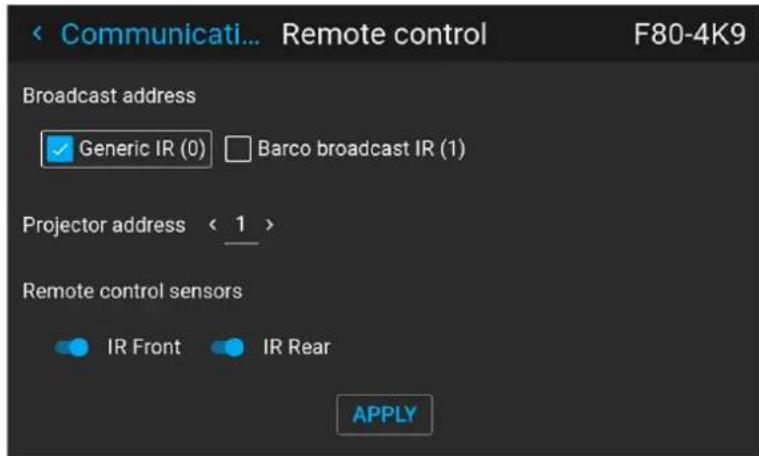
Image 10-2 Example of the Remote control menu
- To change the broadcast address select the radio button of your choice.
The following choices are possible:
-
Generic IR (address 0)
• Barco broadcast IR (address 1) -
Select APPLY and click OK to apply the changes.
10.2.2 Projector address
About individual projector address
As more than one projector can be installed in a room, each projector should be separately addressable with an RCU or with a computer using serial communication. Therefore each projector has its own address. The factory default individual projector address is '0'.
When the address is set, the projector can be controlled with the RCU. Only addresses between 0 and 31 are supported for the RCU.
Next to an individual projector address, each projector has also a broadcast address for group control.
How to change
- In the main menu, select Settings → Communication → IR control.
Image 10-3 Communication menu, Remote Control
The Remote control menu is displayed.
System settings menu
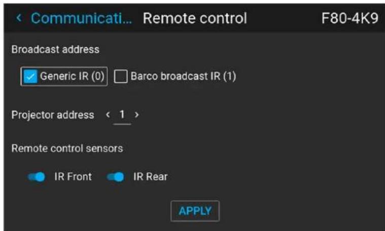
Image 10-4 Example of the Remote control menu
-
Select the current projector address and enter a new address.
-
Select APPLY and click OK to apply the changes.
From now on the projector will only listen to this new address and to its broadcast address.
10.2.3 IR sensors
What can be done?
Each IR sensor can be individually disabled or enabled.
When all sensors are turned off, the projector will no longer respond to signals from the remote control. To re-enable the sensors, use the menu keypad on the projector.
How to disable
- In the main menu, select Settings → Communication → IR Control.
Image 10-5 Communication menu, Remote Control
The IR control menu is displayed.
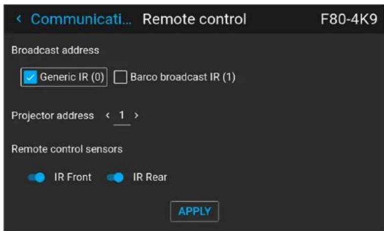
Image 10-6 Example of the Remote control menu
- To disable an IR sensor, select the slider and drag to the left.
A blue slider means an active IR sensor.
A gray slider means an inactive IR sensor.
- Select APPLY and click OK to apply the changes.
10.3 Host name - custom projector name setup
What can be done?
The default host name of the projector is the projector type along with the serial number of your projector (e.g. "UDX-4K40-0123456789").
You can change this name to make it easier to spot in a network with multiple devices or projectors
How to set a different Host name
- In the main menu, select Settings → Communication → Host name.
Image 10-7 Communication menu, Host name
The Host name menu is displayed.
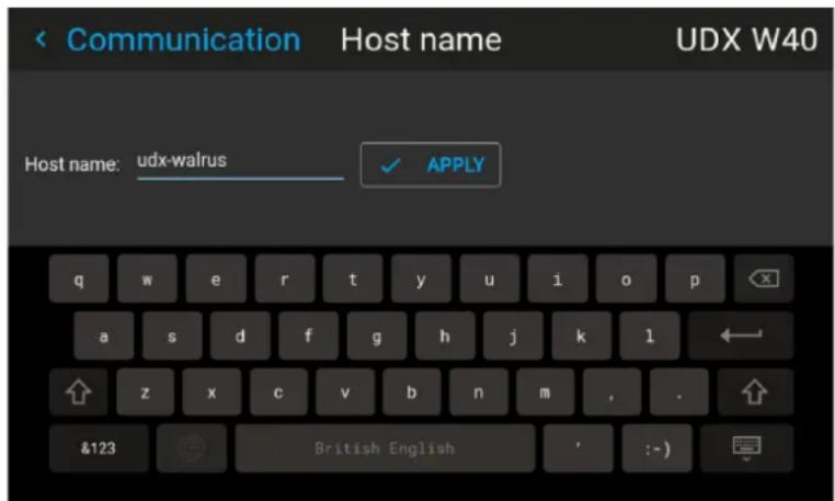
Image 10-8 Example of the host name menu
- Press confirm to edit the Host name field.
- Use the digital keyboard to change the Host name to the desired custom name.
- Press the OK key, or press the enter icon to confirm the typed name. Click Apply to update the host name.
10.4 DMX
About the ways to control the projector via DMX
DMX signals can be connected to the DMX In port on the communicator interface when using a standard DMX cable equipped with XLR connector. The DMX out can be used to create a chain of DMX devices. One universe can control up to 512 channels.
If you are using a DMX console and other automated lighting products compatible with Art-Net, the Ethernet network can serve as the link for DMX control. All DMX controls can be sent over the Ethernet cable. Multiple universes are possible.
About the DMX menu
| DMX Feature | What can be done? |
| DMX Address(Start Channel) | Before a projector can execute DMX commands, a unique address (named “Start Channel”) should be given to the projector.This address can vary from 1 to 512. |
| DMX Mode T | Two different modes for DMX are available.Basic: A basic configuration where 2 channels are implemented.Extended: A full configuration, spread over 14 channels. |
| DMX Monitor | If a DMX device is connected, the settings per channel can be displayed via the Monitor button. |
| Art-Net DMX | DMX can be sent via the Ethernet connector to the projector instead of the classic DMX connector. This function can be enabled or disabled. Art-Net is generally used when more than 512 addresses are used in your setup. |
| DMX Universe | Note:DMX Universe can only be used when Art-Net DMX is enabled.If Art-Net is enabled, you can specify to which DMX universe this projector belongs to. |
| DMX Power Down | The projector can be forced to shut down after a certain time-out period (in minutes) if no DMX signals are available. |

For full mapping of each used channel, refer to the DMX chart in the appendices, see User guide.
How to set up DMX?
- In the main menu, select Settings / Communications / DMX.
Image 10–9
The DMX menu is displayed.
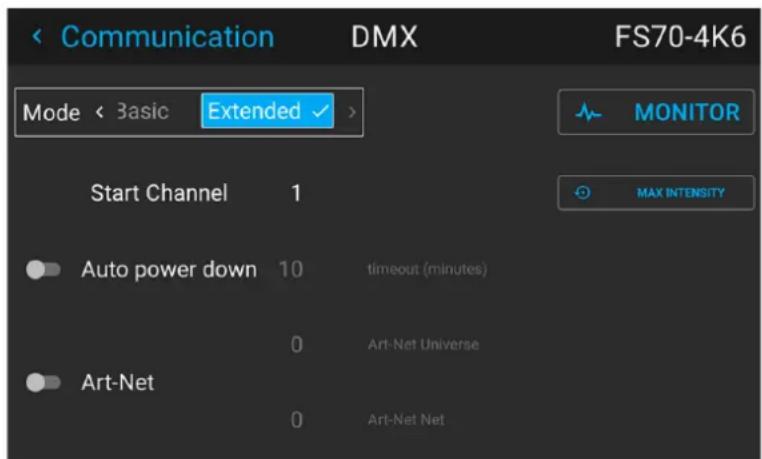
Image 10–10
- Choose the desired DMX mode.
- Choose the desired starting channel.
- Choose whether or not you want the Auto power-down feature to be enabled. If enabled, determine the time-out.
- If required, enable Art-Net. If enabled, determine the desired Art-Net Universe and Art-Net channel.
10.5 Trigger
About
There are 3 trigger outputs (2 on the F40 series) on the projector; one in the front and two on the back panel. These outputs can be used for controlling external equipment.
The trigger outputs can be individually set to active low or active high by entering the menu Settings / Communication / Triggers
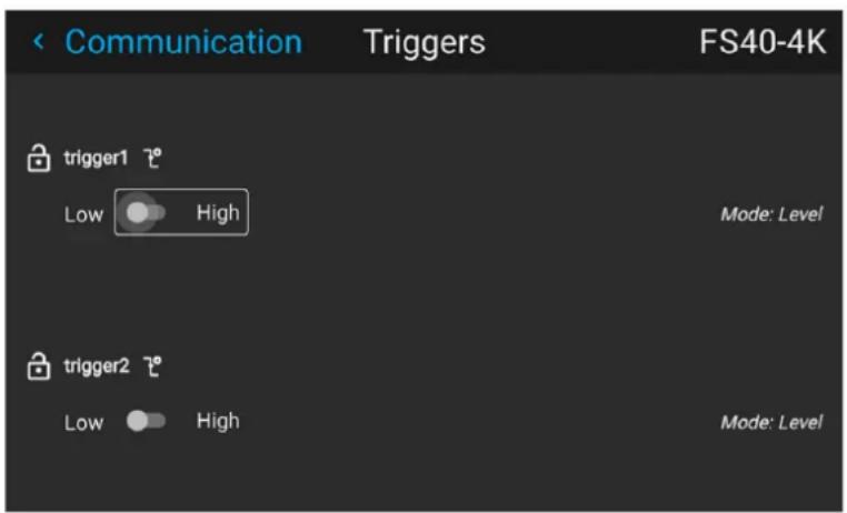
Image 10–11 F40 series trigger menu
The time of trigger output is defined via an API code. Contact Barco support for detailed info.
10.6 Language
Setting the menu language
The menu language can be changed to a suitable language.
Enter the menu Settings / User Interface / Language
Use the arrow keys on the remote to select a language.
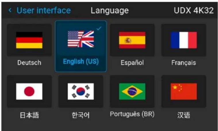
Image 10–12
All menus and icons will change to the selected language.
10.7 Themes
About
Enter the menu Settings / User interface /Themes
Themes are used to apply a predefined functionality to the OSD display. There are two options: light (default) or dark. (From software version 1.5, the "Dark" theme is the default.)
It is the "Dark" option that is shown in the menu screenshots in this manual, as this gives a better rendering.
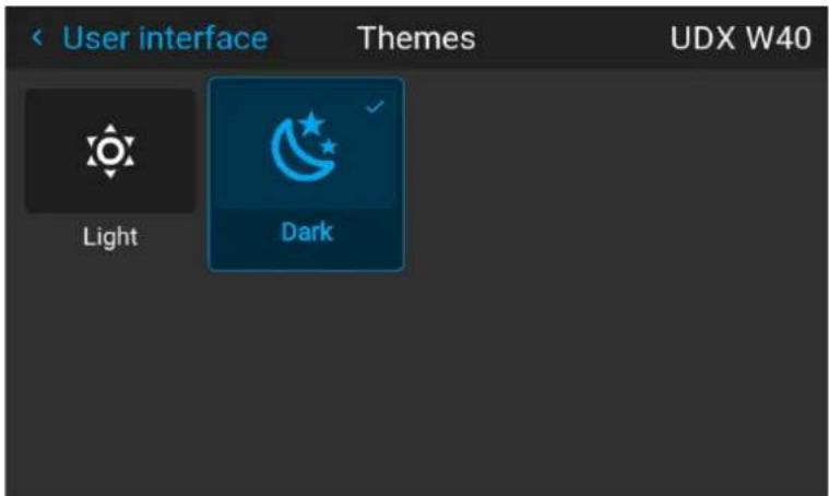
Image 10–13 Select theme, dark or light.
10.8 Units
About
Enter the menu Settings / User interface / Units
Units are used to set the preferred units of measurements for temperature and distance.
Enter the menu and select the preferred units by the arrow keys on the remote control.
Temperature units: Celsius (C) and Fahrenheit (F).
Distance units: Meter (M), Centimeters (C), Feet (FT) and Inches (IN)
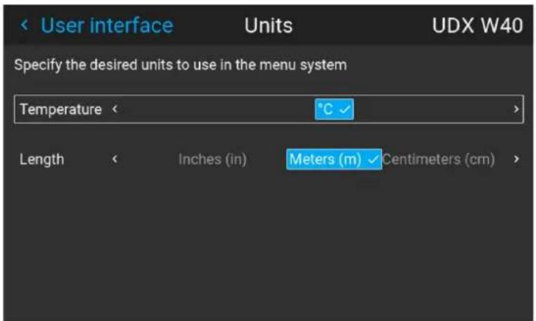
Image 10–14 Select temperature unit
10.9 Backlight
About backlight settings
Enter the menu Settings / User interface / Backlight
The backlight menu shows up.
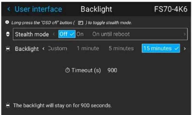
Image 10–15
Setting the backlight modes
- Stealth mode: With this enabled, the backlight on the LCD and the buttons will be always off. The indication LED's for the HDbaseT and LAN will also be disabled.
When "On until Reboot" is enabled, the backlight on the LCD will be on during reboot, and en power transition cycle (on/ready state to eco mode, and back again). - Backlight: Select the time delay for turning off the LCD backlight. There are several predefined values, and also possible to set a custom value.
10.10 ECO mode
About Standby ECO
When the ECO mode is enabled, the projector will automatically go to ECO standby mode after a time-out (default 15 minutes). All electronics (including fans, pumps, ...) go down except for a very small wake-up controller. See section dedicated to the Power Mode transitions for further details.

Until recently, it was not possible to navigate through the on-screen display (OSD) of the projector while in Ready mode. This feature has been implemented from software version 1.7 onward.
How to enable/disable the ECO mode
- In the main menu, select System Settings.
- In the System Settings menu, choose to either enable or disable ECO mode by using the ECO mode slider. While ECO mode is available, the slider is colored blue.
Image 10–16 Settings menu, enable ECO mode
10.11 Power settings
About power settings
If the power is off, and there is no activity, the projector will go to standby after a defined time.
Set Power settings timeout
In the power settings menu, the standby timeout can be selected.
Enter the menu Settings / Power settings
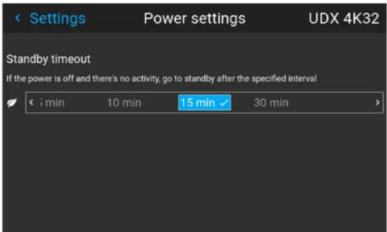
Image 10–17
Select the desired time by the arrow keys on the remote control, and press enter.
10.12 Lens features
About
In order to prevent unintentional lens adjustments, especially after e. g. a completed setup and adjustment, there is a possibility to disable certain lens adjustment functions. These functions are directly accessible via the remote control, and can by that easily be adjusted by accident.
Enter the menu shown below, and disable the desired functions by toggling the desired buttons. The menu below shows all lens options in enabled position.
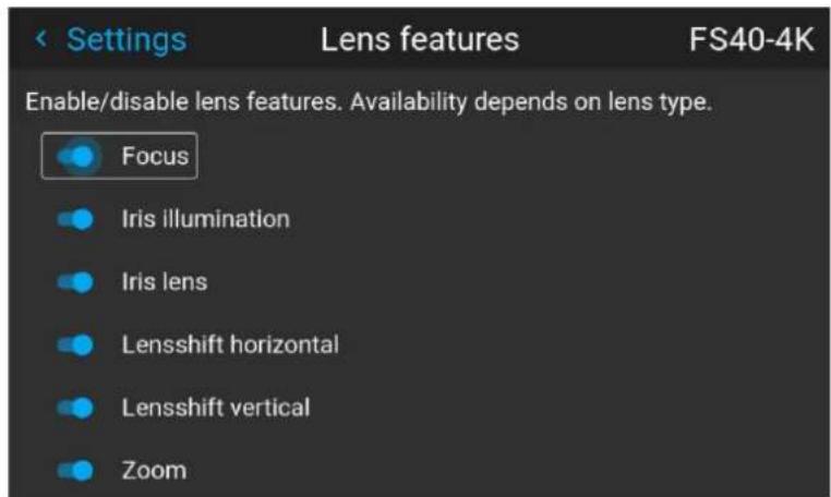
Image 10–18
10.13 24/7 Mode
About 24/7 mode.
This function is intended for installations that operates continuously (24 - 7 operation), and with either High Color or High Brightness color wheels installed in order to increase the product lifetime.

This feature is only valid for the WQXGA / 4K versions of the projector. WUXGA does not have this function available.

Enabling (or disabling) of the 24/7 mode requires a re-calibration of the Real Color P7 color coordinates.
How to set
Enter the menu Settings / 24/7 mode
Toggle the 24/7 function on and off by pressing the OK button on the remote control or the keypad.
Image 10–19
10.14 Maintenance
About
Settings / Maintenance
The Maintenance Menu is for service personnel and / or advanced users only. Sub – menus are Reset and Lens Calibration.
By entering a service code (or advanced user code), more features are available. This features will be visualized via the new tiles that shows up after entering the code.
See the Service Manual for detailed information regarding service issues.
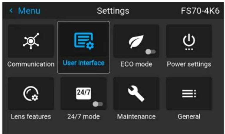
Image 10-20 Maintenance Menu
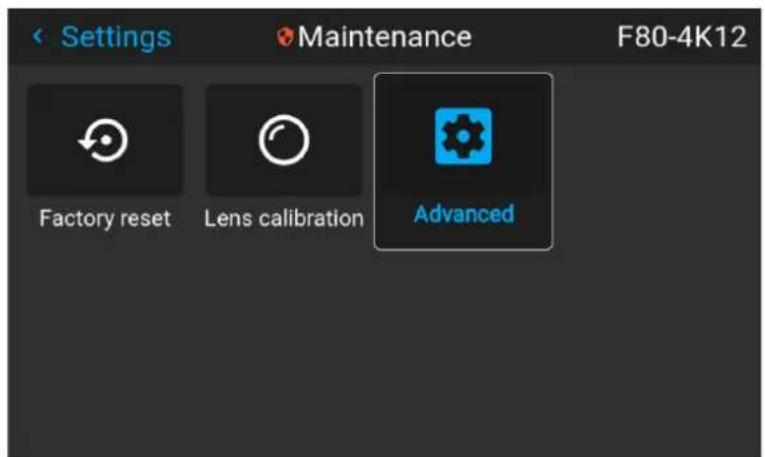
Image 10-21 Maintenance Sub-menu
10.15 Lens calibration
About calibration
This function will calibrate the position of the iris and the horizontal and vertical lens shift. The purpose is to have an accurate feedback to the system
Calibration
- Enter the menu Settings / Maintenance / Lens calibration.
- Select the feature that shall be calibrated, and press enter on the remote control
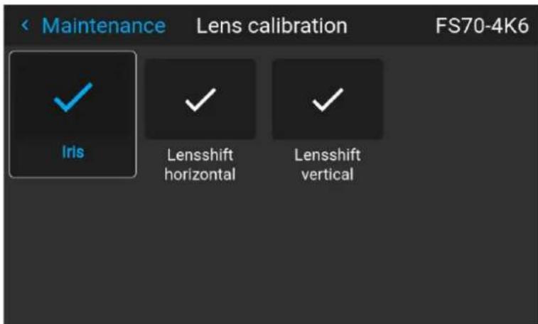
Image 10-22
- Press enter to execute.
10.16 Reset
What can be done?
All settings and values on the projector can be reset to its default values. This can be done for one or more settings separately, or all settings together (factory reset).
Default settings
The following settings are default settings:
| Topic Setting | Default value | |
| UserInterface Theme Dark | ||
| Network Communication LAN, Automatic settings | ||
| System Eco Mode (if applicable) | Available | |
| Screen | Screen luminance - Unit | nits |
| Optics | High Contrast | Off |
| Illumination | Power | 100% |
| ImageConnector | Color Space | auto |
| Signal Range | auto | |
| ImageResolution | Output Resolution (if applicable) | 4K UHD |
| ImageWarp | Screen size | 5120x3200 / 2560x1600 |
| 4 cornerBow | Warp off, no warp | |
| Warp files | Disabled, no files selected | |
| ImageBlend | Blend/Mask sizeBlack Level | disabled, all value to zero |
| Black Level FilesBlend Files | Disabled, no files selected | |
| ImageRealColor | P7 Realcolor | all set to native |
| ImageStereo | Sync delaySwap eye Off | 0 μs |
| Dark time lowest value available | ||
| ImageDisplay Display mode Auto Stereo | ||
| ImageOrientation Orientation Table, Front | ||
| ImageSource Source files Standard | ||
| ImageFeatures Contrast mid value | ||
| Brightness | mid value | |
| Saturation | mid value | |
| Sharpness | mid value | |
| Gamma | mid value | |
| Cropping (if applicable) | Off | |
| Aspect Ratio (if applicable) | 16:9 | |
How to reset all projector settings
- In the main menu, select Settings / Reset.
- In the Reset menu, select RESETALL and click OK.
How to reset one or more projector settings
- In the main menu, select System Settings → Reset. The Reset menu is displayed.
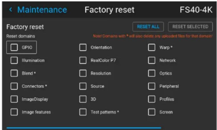
Image 10–23 Reset menu
- Navigate to the checkbox next to the settings that need to be reset and press OK.
Multiple selections are possible. - Select RESET and press OK to reset all selected settings.

Domains with * will also delete any uploaded files for that domain.
10.17 Controlling the backlight of the LCD Display
What lighting can be controlled?
You can choose how quickly the backlight of the LCD turns off. You can select one of the default values, or enter a custom value.
Stealth Mode
Alternatively, you can turn on Stealth Mode instead. By activating this mode, the backlight of the LCD, the backlight of all the buttons of the keypad and the indication LEDs for the LAN and HDbaseT inputs will be disabled.
Stealth Mode is enabled and disabled by pressing the OSD button on the remote control for 3 seconds.
How to set the backlight
- In the main menu, Settings → User interface → Backlight.
Image 10-24 Settings menu, backlight
The Backlight menu will be displayed.
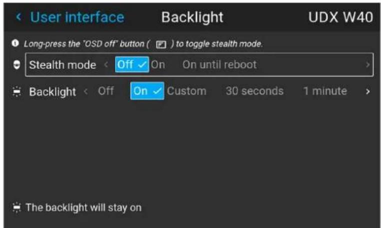
Image 10-25 Example of the backlight menu
- Choose the desired setting for the backlights. Select one of the predetermined options, or a custom value.
GUI - Status menu 11
11.1 Status menu overview.... 164

No settings can be modified in the status menu. Its only for consulting.
11.1 Status menu overview
How to access the status menu
While in the main menu, press Status.
Image 11-1 Main menu, status
The status menu is displayed.
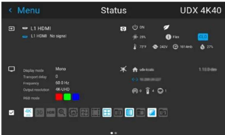
Image 11-2 Example of the first page of the status menu
Swipe the screen left of right to swap between the Status pages.
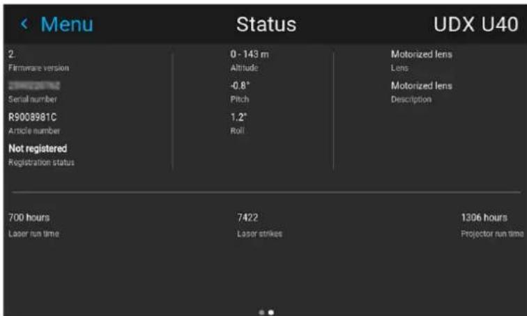
Image 11-3 Example of the second page of the Status menu
What can be seen on the Status page?
- Connected source and signal details
- Display settings (e.g. display mode, transport delay, output resolution, etc)
- Projector power and environmental details (e.g. power, temperature, pressure, etc)
• Network status (e.g. host name, IP address, software version)
• Active function icons (e.g. warp, blend, files, etc). Active functions are highlighted, while inactive functions are muted.
What can be seen on the About page?
- Projector information, e.g. firmware version, serial number, projector article number and registration status (only if applicable for your device)
- Mounted lens: Lens type and Lens description (if available).
- Installation information: Altitude, pitch angle, roll angle, distance (only if applicable for your device)
- Basic statistics, Light source run time, light source strikes, projector runtime.
3D
12
12.1 Setup 3D mode....168
3D setup
The projector is capable of displaying 3D images and movies in both active and passive stereo 3D input mode.
Setup of a 3D installation requires an advanced understanding of the 3D systems, both for the projector, and also for the signal source.
Regarding setup of the signal source, refer to the user manual for the specific unit.
In 3D setup, it is crucial that the projected images are perfectly synchronized through the whole signal path, from the signal source to the picture viewed through the 3D goggles.
See instructions in this chapter to set up the projector for this feature.
Active stereo input.
One channel input. (One cable). Update frequency @ 120 Hz. Extra sync. signal must be used when DVI source is used. For Displayport source, the sync signal is present in the signalcable, but external sync can also be used when necessary.
Passive stereo input.
Use two channel input (two cables), one for each eye. Update frequency limited to 60 Hz for each channel. Dual Sequential input source (DVI or Displayport) must be used. No external sync signal required.
12.1 Setup 3D mode.
Setup 3D mode.
-
Enter the Source menu, and select the desired input source.
-
For active stereo input, select Displayport 1, DVI-1, HD BaseT or HDMI.
-
For passive stereo input, select Dual displayport sequential, or Dual DVI sequential
-
Enter the menu Installation3D setup
When in 'auto stereo' display mode, the product shall automatically switch to 'active stereo' mode and project synchronously at n times the input frequency - where n is as high as possible on the individual products.
- Roll down in the menu and select the Auto stereo selection in the Display mode menu.
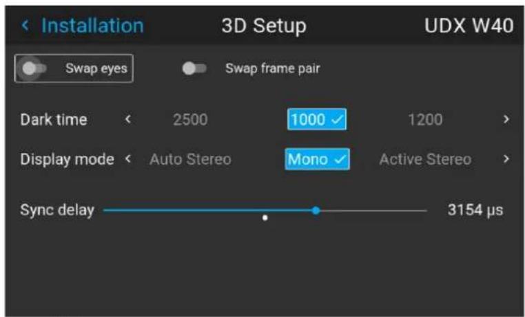
Image 12-1
- When a HDMI 3D source is detected, it is shown in the source status that this is a 3D source.
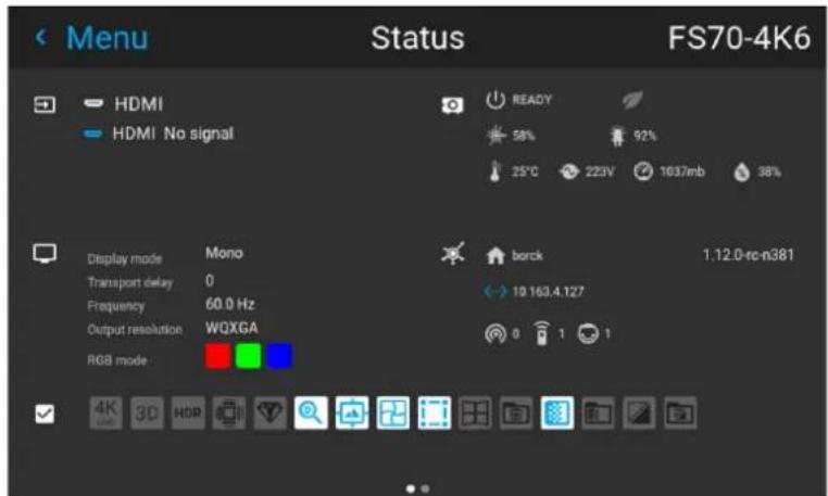
Image 12-2
- Enter the menu Installation/3D Setup, and select the necessary dark time. The projector detect the color wheel, and only one option is available, depending on the color wheel.
Available color wheels with their respective dark times are :
-
DCI: 1600us
• High Brightness: 1660us
• Color: 1850us -
Run a 3D image or movie from the source.
Put on the 3D goggles, and verify by looking through the goggles with one eye at the time that only one image is visible in each eye. A double picture or a shade of the picture from the other side shall not be
observed. Repeat for both sides, and adjust the Sync Delay slider until a “clean” picture is visible in each eye.
If the 3D picture looks a bit “strange” through the 3D goggles, the solution is to swap eyes by enabling the Swap eyes button in the menu.

Note: There is also a 3D test pattern available. Go to the menu Test Patterns/Internal Select the 3DSTEREO pattern.
The test pattern menu also have a shortcut key on the remote control and the keypad.
Why change the 3D setup?
While Barco can provide a 3D emitter and active shutter glasses as options to this projector, you are also free to use a 3D emitter and active shutter glasses of your own choice. Since glasses and emitter can have various specifications compared to the ones Barco can provide, the 3D setup menu allows you to configure the output image to the specifications of your glasses and emitter. The following can be configured:
- Swap Eye: You can choose to invert the stereo Sync output signal (depending on the chosen 3D emitter and glasses).
- Swap frame pair: You can choose to invert the stereo input signal (depending on the chosen source input).
- Dark time: Pre defined, dependent on the color wheel installed. See item 11.1.4 above.
- Stereo glasses: Active 3D glasses must be used.
- Sync Delay: You can increase or decrease the sync delay. The scale goes from -10 000 s to +10 000 s with a step of 100 s.
Image 12–3
Upgrade projector firmware
13
13.1 Upgrade procedure.... 172
13.1 Upgrade procedure

CAUTION: Do NOT power down or remove mains power supply when an upgrade is in progress.

Once initiated, the upgrade procedure can take up to 20 minutes to complete. The LCD display will show the progression and status of the upgrade during the process.
Update
- Go to www.barco.com and select your product. All available firmware downloads are filed under the Technical Downloads tab.
- Download the firmware. Extract and save the file to a USB stick with FAT file system. Use the eject function on your PC to safely remove the device from the computer.
- Place the projector in Ready mode (status indicator is steady White).
- Insert the USB Stick in to the rear USB port on the projector.
After a few seconds, the status indicator will flash. (rate: 3 Hz/180 FPM). This signals that the upgrade is in progress. If the upgrade file is corrupt or invalid, the status indicator will turn red and the upgrade process will stop. Note! The upgrade will not be installed in this instance, and the upgrade process must be restarted with a full and correct file. The projector may restart several times during the upgrade process - The LCD display will show the progress of the update procedure, and also when the USB stick can be removed. The projector will return to standby mode (status indicator is steady amber) once the upgrade is completed successfully.
User maintenance — Cleaning the projector
14
14.1 Projector lenses.... 174
14.2 Projector cabinet 174
14.3 Filters 174
14.1 Projector lenses
General guidelines for cleaning projector lenses
Blow off dust with clean compressed air (or pressurized air cans).
Use lens cleaner and a clean lens cleaning cloth to remove the dust and contamination.
Wipe in broad strokes, in one direction only.
Warning: Do not wipe back and forwards across the lens surface as this tends to grind dirt into the coating.
Use a dry clean lens cleaning cloth to remove left liquid or stripes. Polish with small circles.
If there are still fingerprints on the surface, repeat with lens cleaner and a clean lens cleaning cloth, then polish again with a dry cloth.

If smears occur when cleaning lenses, replace the cloth. Smears are the first indication of a dirty cloth.
14.2 Projector cabinet

WARNING: Always disconnect the projector from the mains power net before attempting to clean the projector cabinet.
General guidelines for cleaning the projector cabinet (exterior only)
Clean the housing of the projector with a damp cloth. Stubborn stains may be removed with a cloth lightly dampened with a mild detergent solution.
14.3 Filters
General info regarding Air intake and filters.
The product is shipped default without any filters and by avoiding filters, the ventilation system operates for longer periods between maintenance, since no clogging of filters means more air is allowed through the system, resulting in lower operating temperatures over time. The air intake are just protected by a mesh. This mesh has to be vacuum cleaned occasionally when needed. No specific interval for this operation, but to be performed when needed.
For more demanding surrounds both smoke and dust filters can be applied externally to the system to avoid internal fouling.
General guidelines for cleaning projector filters (external)
Remove the filter from the projector then use a vacuum to remove excess dust from the filter. Do not wet or soak the filter.

Cleaning of the projector filter should be done in a separate room to avoid dust contamination.
Technical Specifications
15
About
The information in this section is subject to changes without any notice. For current technical information, visit the product website, or contact your sales support representative.
15.1 F70 4k6
| Brightness 4800 ANSI Lumens minimum | |
| Contrast ratio 1800:1 sequential, 50,000:1 dynamic | |
| IR for NVG no | |
| Brightness uniformity 90% | |
| Aspect ratio 16:10 native | |
| Projector type 1DLP laser phosphor | |
| Resolution 3,840 x 2,400 / 3,840 x 2,160 / 2,560 x 1,600 (native) | |
| Lens type FLD-series | |
| Optical lens shift Vertical up to 146%, depending on lensHorizontal up to 70%, depending on lensMotorized zoom and focus (+ lens memory FLDX lenses)Motorized lens shift (with position memory on all lenses) | |
| Color correction P7 RealColorTM | |
| CLO (constant light output) Yes | |
| Light source | Laser phosphor |
| Light source lifetime | Up to 60,000 hours, depending on mode of operation |
| Sealed DLPTM core | Yes |
| Orientation | 360° rotation, no restrictions |
| 3D | Active stereoscopic 3D |
| Image processing | Embedded warp & blend engine |
| Keystone correction | Yes |
| Inputs | HDSDI2x DP1.22x dual link DVI-IHDBaseTHDMI2.0 (HDCP2.2, HDR10)RJ 45 EthernetDMX in/outRS232 in2x USB12v out |
| Input resolutions | Including and up to:3,840 x 2,400 @ 60Hz3,840 x 2,160 @ 60Hz4,096 x 2,160 @ 60Hz2,560 x 1,600 @ 120Hzrefresh rates:24Hz to 120Hz for WQXGA (2560x1600) and 24Hz to 60Hz for 4K/4KUHD(4096 x 2160/ 3860 x 2400) |
| Software tools | Projector Toolset |
| Control IR, RS232, RJ45 | |
| Network connection IR, RS232, RJ45 | |
| Power requirements 100-240V / 50-60Hz | |
| Power consumption 743 W | nominal, 1100 W maximum |
| BTU per hour Max 4,000 BTU/h | |
| Noise level (typical at 25°C)77°F | 86 dB(A) |
| Operating temperature 10 - | 40 °C (sea level) |
| Storage temperature -20 to | 60 °C |
| Operating humidity 20 - 80% RH | |
| Storage humidity 10 - 90% | RH |
| Dimensions (WxLxH) 475 x | 593 x 286 mm / 18,7 x 23,3 x 11,2 in |
| Weight 37 kg / 81,5 lbs | |
| Standard accessories Power cord, wireless remote control | |
| Certifications CE, FCC Class A and cNus | |
| Warranty | Limited 3 years parts and labor. Extendable up to 5 years |
15.2 F70 W6
F70 W6
| Brightness | 5300 ANSI Lumens minimum |
| Contrast ratio | 1,800:1 sequential, 50,000:1 dynamic |
| IR for NVG | no |
| Brightness uniformity | 90% |
| Aspect ratio | 16:10 |
| Projector type | 1DLP laser phosphor |
| Resolution | 1,920 x 1,200 (WUXGA) |
| Lens type | FLD-series |
| Optical lens shift | Vertical up to 134%, depending on lensHorizontal up to 70%, depending on lensMotorized zoom and focus (+ lens memory FLDX lenses)Motorized lens shift (with position memory on all lenses) |
| Color correction | P7 RealColorTM |
| CLO (constant light output) | Yes |
| Light source | Laser phosphor |
| Light source lifetime | Up to 60,000 hours, depending on mode of operation |
| Sealed DLP ^TM core | Yes |
| Orientation 360° rotation, no | restrictions |
| 3D Active stereoscopic 3D | |
| Image processing Embedded | warp & blend engine |
| Keystone correction Yes | |
| Inputs HDSDI | 2x DP1.22x dual link DVI-IHDBaseTHDMI2.0 (HDCP2.2, HDR10)RJ 45 EthernetDMX in/outRS232 in2x USB12v out |
| Input resolutions Including and up to:1,920 x 1200 @ 60Hz2,560 x 1,600 @ 120Hzrefresh rates:24Hz to 120Hz for WQXGA (2560x1600) and 24Hz to 60Hz for 4K/4KUHD(4096 x 2160/ 3860 x 2400) | |
| Software tools Projector Toolset | |
| Control IR, RS232, RJ45 | |
| Network connection IR, RS232, RJ45 | |
| Power requirements 100-240V / 50-60Hz | |
| Power consumption 743 W | nominal, 1100 W maximum |
| BTU per hour Max 4,000 BTU/h | |
| Noise level (typical at 25°C386 dB(A)77°F) | |
| Operating temperature 10 - | 40 °C (sea level) |
| Storage temperature | -20 to 60 °C |
| Operating humidity | 20 - 80% RH |
| Storage humidity | 10 - 90% RH |
| Dimensions (WxLxH) | 475 x 593 x 286 mm / 18,7 x 23,3 x 11,2 in |
| Weight | 37 kg / 81,5 lbs |
| Standard accessories | Power cord, wireless remote control |
| Certifications | CE, FCC Class A and cNus |
| Warranty | Limited 3 years parts and labor.Extendable up to 5 years |
15.3 FS70 4k6
FS70 4k6
| Brightness 3,800 ANSI Lumens minimum | |
| Contrast ratio 1800:1 sequential, 50,000:1 dynamic | |
| IR for NVG yes | |
| Brightness uniformity 90% | |
| Aspect ratio 16:10 | |
| Projector type 1DLP laser phosphor | |
| Resolution 3,840 x 2,400 / 3,840 x 2,160 / 2,560 x 1,600 (native) | |
| Lens type FLD-series | |
| Optical lens shift Vertical up to 146%, depending on lensHorizontal up to 70%, depending on lensMotorized zoom and focus (+ lens memory FLDX lenses)Motorized lens shift (with position memory on all lenses) | |
| Color correction P7 RealColorTM | |
| CLO (constant light output) Yes | |
| Light source | Laser phosphor |
| Light source lifetime | Up to 60,000 hours, depending on mode of operation |
| Sealed DLP ^TM core | Yes |
| Orientation | 360° rotation, no restrictions |
| 3D | Active stereoscopic 3D |
| Image processing | Embedded warp & blend engine (Barco Pulse) |
| Keystone correction | Yes |
| Inputs | HDSDI2x DP1.22x dual link DVI-IHDBaseTHDMI 2.0 (HDCP2.2, HDR10)RJ 45 EthernetDMX in/outRS232 in2x USB12v out |
| Input resolutions | Including and up to:3,840 x 2,400 @ 60Hz3,840 x 2,160 @ 60Hz4,096 x 2,160 @ 60Hz2,560 x 1,600 @ 120Hz |
| Software tools | Projector Toolset |
| Control | IR, RS232, RJ45 |
| Network connection IR, RS | 232, RJ45 |
| Power requirements 100-240V / 50-60Hz | |
| Power consumption 743 W | nominal, 1100 W maximum |
| BTU per hour Max 4,000 BTU/h | |
| Noise level (typical at 25°C)77°F | 86 dB(A) |
| Operating temperature 10 - | 40 °C (sea level) |
| Storage temperature -20 to | 60 °C |
| Operating humidity 20 - 80% RH | |
| Storage humidity 10 - 90% | RH |
| Dimensions (WxLxH) 475 x | 593 x 286 mm / 18,7 x 23,3 x 11,2 in |
| Weight 37 kg / 81,5 lbs | |
| Standard accessories Power cord, wireless remote control | |
| Certifications CE, FCC Class A and cNus | |
| Warranty | Limited 3 years parts and labor. Extendable up to 5 years |
15.4 FS70 W6
FS70 W6
| Brightness | 5300 ANSI Lumens minimum |
| Contrast ratio | 1,800:1 sequential, 50,000:1 dynamic |
| IR for NVG | yes |
| Brightness uniformity | 90% |
| Aspect ratio | 16:10 |
| Projector type | 1DLP laser phosphor |
| Resolution | 1,920 x 1,200 (WUXGA) |
| Lens type | FLD-series |
| Optical lens shift | Vertical up to 134%, depending on lensHorizontal up to 70%, depending on lensMotorized zoom and focus (+ lens memory FLDX lenses)Motorized lens shift (with position memory on all lenses) |
| Color correction | P7 RealColorTM |
| CLO (constant light output) | Yes |
| Light source | Laser phosphor |
| Light source lifetime | Up to 60,000 hours, depending on mode of operation |
| Sealed DLP ^TM core | Yes |
| Orientation | 360° rotation, no restrictions |
| 3D Active stereoscopic 3D | |
| Image processing Embedded | warp & blend engine |
| Keystone correction Yes | |
| Inputs HDSDI | 2x DP1.22x dual link DVI-IHDBaseTHDMI 2.0 (HDCP2.2, HDR10)RJ 45 EthernetDMX in/outRS232 in2x USB12v out |
| Input resolutions Including and up to:1,920 x 1200 @ 60Hz2,560 x 1,600 @ 120Hz | |
| Software tools Projector Toolset | |
| Control IR, RS232, RJ45 | |
| Network connection IR, RS232, RJ45 | |
| Power requirements 100-240V / 50-60Hz | |
| Power consumption 743 W | nominal, 1100 W maximum |
| BTU per hour Max 4,000 BTU/h | |
| Noise level (typical at 25°C)77°F | 36 dB(A) |
| Operating temperature 10 - | 40 °C (sea level) |
| Storage temperature -20 to | 60 °C |
| Operating humidity | 20 - 80% RH |
| Storage humidity | 10 - 90% RH |
| Dimensions (WxLxH) | 475 x 593 x 286 mm / 18,7 x 23,3 x 11,2 in |
| Weight | 37 kg / 81,5 lbs |
| Standard accessories | Power cord, wireless remote control |
| Certifications | CE, FCC Class A and cNus |
| Warranty | Limited 3 years parts and labor.Extendable up to 5 years |
Color component mapping
A
A.1 Introduction.... 184
A.2 How infrared is displayed 184
A.3 Default setup....184
A.4 Cloned image with full RGB input....185
A.5 Cloned inputs with only green content for IR 186
A.1 Introduction

This topic is only valid for the FS variant of the projector.
Introduction
In the FS-series projectors, one of the night vision modes is achieved by feeding the projector with two separate inputs, one with content for visible light (VL), and the other with content for the infrared (IR). Outside the projector, these two inputs may have the same content, achieved by a splitter or by cloning the output in the graphics adapter on the image generator (IG).
This topic describes some usage scenarios and the setup to use, to achieve the best performance. It should serve as a guide for how to set up the system or give guidance if the exact user case is not described here.
A.2 How infrared is displayed
How infrared is displayed
In night vision mode with 2 separate inputs, the projector displays the two inputs alternating every other frame. The output is displayed a double speed of the inputs, i. e. at 120Hz in case of 60Hz input. The DMD is illuminated with visible RGB light every other frame, while the IR "light" is illuminating the DMD all the time.
The display device (DMD) itself do not know whether it is displaying IR or VL. And this is causing problems when the actual image content is not carrying all 3 color components (full RGB). As an example, only the red color component is active on the input. The DMD is attempting to display this as an RGB image even if it is illuminated with IR. The result is that the DMD is active only approximately one third of the frame, thereby "wasting" a lot of the IR output power.
In Pulse release 2.1 and onwards, there is an option to create a Color Component mapping per connector input. This gives the flexibility on individual connector to connect DMD "colors" to input color channel.
A.3 Default setup
Default setup
In the default setup, the RGB components of the DMD fetches the content from the RGB component of the inputs. This mode of operation is best suited for when the VS and IR inputs both carries a full RGB image and specially the IR channel has full black/white content if displayed on a regular monitor. This is not a clone or spitted image even if the content in the example below indicates the same image on both inputs.
Display port 1 (VL) Color mapping DMD

flowchart
graph LR
    A["Boeing Flight"] --> B["Cross Section Diagram"]
    B --> C["Post-Flight Flight"]
Image A-1
Displayport 2 (IR)
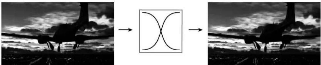
natural_image
Silhouette of an aircraft in flight with a cross-shaped diagram overlay (no text or symbols)Image A-2
This is the default setup, and the properties of the input is as follows:
| Property | Value |
| image.connector.displayport1.colorcomponent.red RED_IN | |
| image.connector.displayport1.colorcomponent.green GREEN_IN | |
| image.connector.displayport1.colorcomponent.blue BLUE_IN | |
| image.connector.displayport2.colorcomponent.red RED_IN | |
| image.connector.displayport2.colorcomponent.green GREEN_IN | |
| image.connector.displayport2.colorcomponent.blue BLUE_IN |
A.4 Cloned image with full RGB input
Cloned image with full RGB input
In this setup the image is rendered for visible light. It has full RGB information. In this setup there is also requested to take the red color component on the input for the IR channel and fully saturate the DMD with this component.
Display port 1 (VL) Color mapping DMD
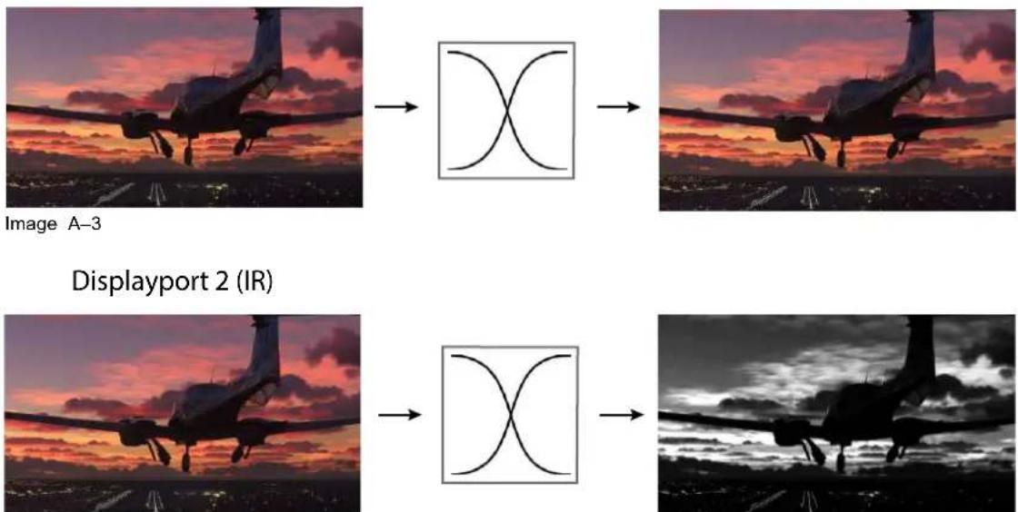
flowchart
graph LR
    A["Image A-3"] --> B["Cross-Scale Diagram"]
    B --> C["Image A-3"]
    D["Displayport 2 (IR)"] --> E["Cross-Scale Diagram"]
    E --> F["Image A-3"]
    G["Image A-3"] --> H["Cross-Scale Diagram"]
    H --> I["Image A-3"]
Image A-4
To achieve this result, use the following settings:
| Property | Value |
| image.connector.displayport1.colorcomponent.red RED_IN | |
| image.connector.displayport1.colorcomponent.green GREEN_IN | |
| image.connector.displayport1.colorcomponent.blue BLUE_IN | |
| image.connector.displayport2.colorcomponent.red RED_IN | |
| image.connector.displayport2.colorcomponent.green RED_IN | |
| image.connector.displayport2.colorcomponent.blue RED_IN |
A.5 Cloned inputs with only green content for IR
Cloned inputs with only green content for IR
In this setup, the input is a fully saturated green and white image, well suited for the IR channel. In this setup, portion of the green image is extracted and applied to the red channel for visible light also. Note that the power of the visible light source must be dimmed to achieve the desired effect.
Display port 1 (VL) Color mapping DMD
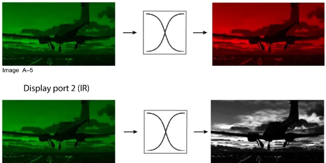
Image A-6
| Property | Value |
| image.connector.displayport1.colorcomponent.red GREEN_IN | |
| image.connector.displayport1.colorcomponent.green OFF | |
| image.connector.displayport1.colorcomponent.blue | OFF |
| image.connector.displayport2.colorcomponent.red GREEN_IN | |
| image.connector.displayport2.colorcomponent.green GREEN_IN | |
| image.connector.displayport2.colorcomponent.blue | GREEN_IN |
Image settings and adjustments for optimal latency
B
B.1 Introduction.... 188
B.2 Latency....188
B.3 DMD display device 188
B.4 Image display....188
B.5 Image positioning 190
B.1 Introduction
Introduction
For projectors used in simulation, latency is always an important component. Barco strives to make latency as small as possible together with optimal image quality.
There are however some parameters of the installation and setup that affects latency. This white paper describes these conditions and gives guidance for how to optimize setup of the projector.
B.2 Latency
Latency
Latency is a measurement of the added time the projector needs to display an image. This is measured from when the first pixel (not v-sync) of an image arrives at the projector until the first light of the same image is being displayed by the projector. This time is measured in milliseconds. The latency is also referred to as transport delay.
Different projector settings affect latency. For example, the amount of warp applied to the image might affect latency since the projector has to wait longer for the required pixels to arrive at the input. As will be shown later, warping can in certain special settings reduce latency compared to a non-warped image.
In a multi projector setup, different projectors most often have different warp settings and thereby different latencies. To keep a full system at the same latency and in sync, each projector has the possibility to add to the latency (transport delay). In a multi-projector setup, all projectors should be set to the same latency as the projector with the highest transport delay.
B.3 DMD display device
DMD display device
Barco projectors uses a DMD device from Texas Instruments to display the image. A DMD device displays the intensity of a pixel by time multiplexing the time it is on over the frame time. If one pixel is 50% grey, it is on 50% of the time for that frame. Since we also change the color of the light during the same frame period, all the DMD mirrors (pixels) must be displayed synchronously. This is done by dividing the image into bitplanes and sending the bitplanes one by one to all the mirrors simultaneously. As a simplistic explanation, consider an 8-bit pr. pixel image. First the LSB bitplane is loaded. All the pixels that has the LSB bit set, has the corresponding DMD mirror turned on for a short time. Next, the second to last bitplane is loaded, and all the DMD mirrors where this bit is set are displayed for twice as long. This continues until the MSB (bitplane 8) is loaded and displayed.
Because of dividing the image into bitplanes, all pixels of an image must be loaded to the DMD before it can start to display any of the pixels.
B.4 Image display
Native image
Consider the following setup, where the incoming image has the same resolution as the DMD device.
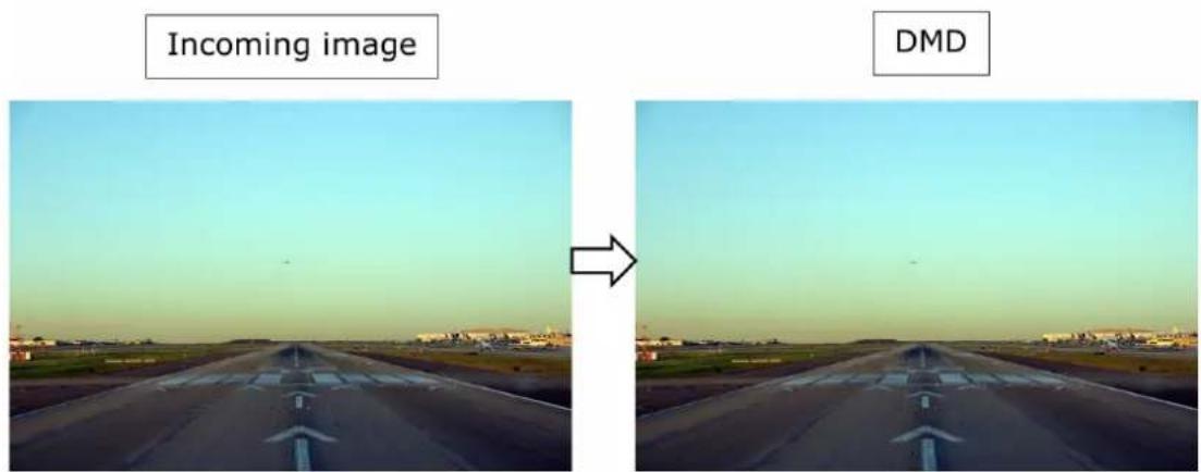
Image B-1
The image is sent to the projector, pixel by pixel, line by line from top left to bottom right. For 60Hz, it takes 16.6667ms for all the pixels to arrive at the projector (disregarding blanking pixels).
Theoretically, as soon as the first pixel arrives, it can be transmitted directly to the DMD. Since incoming and output pixels follow a one-to-one relation, when the last pixel arrives it is sent to the DMD and at that time the DMD can immediately start to divide the image into bitplanes and display the image. This means that the latency never can go below 16.6667ms.
There is more processing being done to the pixels (color analysis, memory handling etc.), so in real life, latency will never be this low.
Non-native image
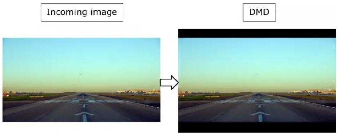
Image B-2
Consider this setup where the incoming image is smaller vertically than the DMD resolution. To maintain correct aspect, the image will be displayed by filling in black pixels above and below on the DMD. The DMD device needs to receive all the pixels it shall display, including the black ones.
In this case, the Pulse image processing will start to prefill the DMD with black pixels before the actual pixels arrive on the input. Then it follows a one-to-one pixel copy until the last incoming pixel has arrived. After that, the additional black pixels are transmitted until the DMD has received all the pixels for a full frame. It is not until then that the image can be displayed.
Therefore, the black pixels at the bottom of the image directly adds to latency since the image cannot be displayed until all the extra black pixels have been transmitted to the DMD.
B.5 Image positioning
Image positioning
From the discussion above, it follows that the incoming image should follow the DMD resolution as much as possible to reduce latency. If this is not possible, the image should be adjusted and positioned as close to the bottom edge (in desktop-front projection mode) of the DMD as possible to have minimum latency.
To position the image on the DMD, it's recommended that the digital image shift is used. This function shifts the image content and is done after the image has been warped. Shifting the image does not degrade pixel quality and no scaling is used for this functionality.
Another option is to use the warp settings itself, either the 4-corner coordinates of the warp mask or the warp grid calculated externally. Always adjust the warp grid to position it as close to the bottom of the image as possible.
A curious effect of this is when applying keystone warp to an image smaller than DMD resolution and the output is adjusted down as discussed above. In the following example some keystone (4-corner adjustment) is applied.
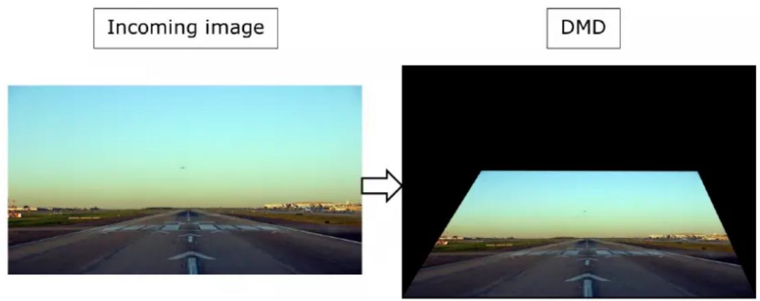
Image B-3
In this setup, the projector latency will in fact be lower than the uncorrected image. This is because the output image has fewer active lines than the incoming image. All the incoming lines are used in the warp calculations, but the resulting image consists of fewer active lines than the original. The projector can take advantage of this by preloading the DMD with black lines before the actual content. Note that for a 60Hz system, latency will never go below 16.66667ms because the DMD is displaying the image synchronously with the refresh of the incoming image.
DMX Chart
C
C.1 DMX chart, Basic.... 192
C.2 DMX chart, Extended....193
C.1 DMX chart, Basic
Overview
| Ch. | Function Value | Default Action | ||
| 1 | Shutter + Intensity 0 | -7 255 Close shutter | ||
| 8 - 255 Adjust intensity | ||||
| 2 | Function select 0 - 7 | 0 No function | ||
| 8 - 15 Activate first | profile preset (If held for 1 second) | |||
| 16 - 23 Activate second | profile preset (If held for 1 second) | |||
| 24 - 31 Activate third | profile preset (If held for 1 second) | |||
| 32 - 39 Activate fourth | profile preset (If held for 1 second) | |||
| 40 - 47 Activate fifth | profile preset (If held for 1 second) | |||
| 48 - 55 Activate sixth | profile preset (If held for 1 second) | |||
| 56 - 63 Activate seventh | profile preset (If held for 1 second) | |||
| 64 - 71 Activate eighth | profile preset (If held for 1 second) | |||
| 72 - 79 Activate ninth | profile preset (If held for 1 second) | |||
| 80 - 87 Activate tenth | profile preset (If held for 1 second) | |||
| 88 - 95 Select input 1: HDMI Input (If held for 1 second) 4 | ||||
| 96 - 103 | Select input 2: DisplayPort Input (If held for 1 second) | |||
| 104 - 111 | Select input 3: SDI Input A (If held for 1 second) | |||
| 112 - 119 | Select input 4: SDI Input B (If held for 1 second) | |||
| 120 - 127 | Select input 5: HDBaseT Input 1 (if held for 1 second) | |||
| 128 - 135 | Select input 6: Quad SDI input (if held for 1 second) | |||
| 136 - 143 | Select input 7: Quad DP board Input A (if held for 1 second)5 | |||
| 144 - 151 | Select input 8: Quad DP board Input B (if held for 1 second)5 | |||
| 152 - 159 | Select input 9: Quad DP board Input C (if held for 1 second)5 | |||
| 160 - 167 | Select input 10: Quad DP board Input D (if held for 1 second)5 | |||
| 168 - 175 | Select input 11: Quad DP board Inputs A-B (if held for 1 second)5 | |||
| 176 - 183 | Select input 12: Quad DP board quad column mode (if held for 1 second) | |||
| 184 - 207 | Reserved for future functionality | |||
| 208 - 115 | Power on / Light source on (If held for 5 seconds) | |||
| 216 - 223 | Power down / Light source off (if held for 5 seconds) | |||
| 224 - 255 | Reserved for future functionality | |||
C.2 DMX chart, Extended
Overview
| Ch. | Function Value | Default Actions | ||
| 1 | Shutter + Intensity 0 | -7 255 Close shutter | ||
| 8 - 255 Adjust intensity | ||||
| 2 | Brightness 0 - 255 | 128 Adjusts the brightness between 0 and 100% on input. | ||
| 3 | Contrast 0 - 255 128 | Adjusts the contrast between 0 and 100% on input | ||
| 4 | Input selection | 0 - 7 | 0 No function | |
| 8 - 15 | Activate first profile preset (If held for 1 second) | |||
| 16 - 23 | Activate second profile preset (If held for 1 second) | |||
| 24 - 31 | Activate third profile preset (If held for 1 second) | |||
| 32 - 39 | Activate fourth profile preset (If held for 1 second) | |||
| 40 - 47 | Activate fifth profile preset (If held for 1 second) | |||
| 48 - 55 | Activate sixth profile preset (If held for 1 second) | |||
| 56 - 63 | Activate seventh profile preset (If held for 1 second) | |||
| 64 - 71 | Activate eighth profile preset (If held for 1 second) | |||
| 72 - 79 | Activate ninth profile preset (If held for 1 second) | |||
| 80 - 87 | Activate tenth profile preset (If held for 1 second) | |||
| 88 - 95 | Select input 1: HDMI Input (If held for 1 second)4 | |||
| 96 - 103 | Select input 2: DisplayPort Input (If held for 1 second)4 | |||
| 104 - 111 | Select input 3: SDI Input A (If held for 1 second) | |||
| 112 - 119 | Select input 4: SDI Input B (If held for 1 second)4 | |||
| 120 - 127 | Select input 5: HDBaseT Input 1 (if held for 1 second) | |||
| 128 - 135 | Select input 6: Quad SDI input (if held for 1 second) | |||
| 136 - 143 | Select input 7: Quad DP board Input A (if held for 1 second)5 | |||
| 144 - 151 | Select input 8: Quad DP board Input B (if held for 1 second)5 | |||
| 152 - 159 | Select input 9: Quad DP board Input C (if held for 1 second)5 | |||
| 160 - 167 | Select input 10: Quad DP board Input D (if held for 1 second)5 | |||
| 168 - 175 | Select input 11: Quad DP board Inputs A-B (if held for 1 second)5 | |||
| 176 - 183 | Select input 12: Quad DP board quad column mode (if held for 1 second) | |||
| 184 - 255 | Reserved for future functionality | |||
| 5 | Focus (MSB) | 0 - 255 128 Set coarse lens focus adjustment6 | ||
| 6 | Focus (LSB) | 0 - 255 128 Set fine lens focus adjustment | ||
| 7 | Zoom (MSB) | 0 - 255 128 Set coarse lens zoom adjustment | ||
| 8 | Zoom (LSB) | 0 - 255 128 Set fine lens zoom adjustment | ||
| 9 | Lens shift vertical (MSB) | 0 - 255 | 128 Set coarse | lens shift in vertical direction |
| 10 | Lens shift vertical (LSB) | 0 - 255 | 128 Set fine | lens shift in vertical direction |
| 11 | Lens shift horizontal (MSB) | 0 - 255 | 128 Set coarse | lens shift in horizontal direction |
| 12 | Lens shift horizontal (LSB) | 0 - 255 | 128 Set fine | lens shift in horizontal direction |
| 13 | Light Source Power7 | 0 - 30 | Set light source to 100% | |
| 4 - 7 Set light source to 95% | ||||
| 8 - 11 Set light source to 90% | ||||
| 12 - 15 Set light source to 85% | ||||
| 16 - 20 Set light source to 80% | ||||
| 21 - 23 Set light source to 75% | ||||
| 24 - 27 Set light source to 70% | ||||
| 28 - 31 Set light source to 65% | ||||
| 32 - 35 Set light source to 60% | ||||
| 36 - 39 Set light source to 55% | ||||
| 40 - 43 Set light source to 50% | ||||
| 44 - 47 Set light source to 45% | ||||
| 48 - 51 Set light source to 40% | ||||
| 52 - 55 Set light source to 35% | ||||
| 56 - 59 Set light source to 30% | ||||
| 60 - 63 Set light source to 25% | ||||
| 64 - 67 Set light source to 20% | ||||
| 68 - 71 Set light source to 15% | ||||
| 72 - 75 Set light source to 10% | ||||
| 76 - 79 Set light source to 5% | ||||
| 80 - 87 Power on / Light source on (If held for 5 seconds) | ||||
| 88- 95 | Power down / Light source off (if held for 5 seconds) | |||
| 96 - 255 | Reserved for future functionality | |||
| 14 | Various | 0 - 70 | Reserved for Calibrate lens | future functionality |
| 8 - 15 | zoom & focus (if held for 5 seconds) | |||
| 16 - 23 | Calibrate lens | horizontal and vertical shift (if held for 5 seconds) | ||
| 24 - 31 | Calibrate lens | (zoom, focus and shift) (if held for 5 seconds) | ||
| 32 - 255 | Reserved for future functionality | |||
Overview video timings for video interfaces
D
D.1 Overview video timings 196
D.2 Overview video timings SDI Inputs 197
D.3 Overview video timings HDMI 2.0 inputs....198
D.4 Overview video timings DisplayPort 1.2 inputs 200
D.5 Overview video timings HDBaseT input 201
D.6 Overview video timings DVI Inputs 203
About resolution in this chapter
Resolutions and video timings indicated in the following sections are resolutions accepted in input of the projector, but the output stays limited to the maximum resolution indicated in the specifications of the device.
D.1 Overview video timings
List of compatible signals
The following table specifies the video signals that the projector can project. Barco Events projectors supports the signal with "X" in the Compatible signals column.
Note: Support for refresh rates 24.00, 30.00, 60.00 Hz automatically includes support of 1/1.001 x those refresh rates.
| Resolution | Vertical refresh rate (Hz) | Compatible signal | ||||
| HDMI 2.0 Input | 12G SDI | DisplayPort 1.2 Inputs | HDBaseT Input | DVI Inputs | ||
| 640 x 480 | 60 X — X X | X | ||||
| 720 x 480 | 60 X — — X | — | ||||
| 720 x 576 | 50 X — — X | — | ||||
| 800 x 600 | 60 X — X X | X | ||||
| 1024 x 768 | 60 X — X X | X | ||||
| 1280 x 720 | 24 — X — | — — | ||||
| 1280 x 720 | 25 — X — | — — | ||||
| 1280 x 720 | 30 — X — | — — | ||||
| 1280 x 720 | 50 X X X X | X | ||||
| 1280 x 720 | 60 X X X X | X | ||||
| 1280 x 800 | 60 X — X X | X | ||||
| 1280 x 960 | 60 X — X X | X | ||||
| 1280 x 1024 | 60 X — X X | X | ||||
| 1400 x 1050 | 60 X — X X | X | ||||
| 1600 x 1200 | 60 X — X X | X | ||||
| 1600 x 1200 | 120 | — — X — | — | |||
| 1920 x 1080 | 24 X X X X | X | ||||
| 1920 x 1080 | 25 X X — | X X | ||||
| 1920 x 1080 | 30 X X — | X X | ||||
| 1920 x 1080 | 50 X X X X | X | ||||
| 1920 x 1080 | 60 X X X X | X | ||||
| 1920 x 1080 | 120 | — — X — | — | |||
| 1920 x 1200 | 50 X X X X | X | ||||
| 1920 x 1200 | 60 X X X X | X | ||||
| 1920 x 1200 | 120 | — — X — | — | |||
| 2048 x 1080 | 24 X — X X | X | ||||
| 2048 x 1080 | 25 X — X X | X | ||||
| 2048 x 1080 | 30 X — X X | X | ||||
| 2048 x 1080 | 48 X — X X | X | ||||
| 2048 x 1080 | 50 X X X X | X | ||||
| 2048 x 1080 | 60 X X X X | X | ||||
| 2048 x 1080 | 120 — — X | — — | ||||
| 2560 x 1600 | 50 X — X X | X | ||||
| 2560 x 1600 | 60 X — X X | X | ||||
| 2560 x 1600 | 120 — — X | — — | ||||
| 3840 x 2160 | 24 X — X X | X | ||||
| 3840 x 2160 | 25 X — X X | X | ||||
| 3840 x 2160 | 30 X — X X | X | ||||
| 3840 x 2160 | 50 X X X — | — | ||||
| 3840 x 2160 | 60 X X X — | — | ||||
| 3840 x 2400 | 24 — — — | — X | ||||
| 3840 x 2400 | 25 — — — | — X | ||||
| 3840 x 2400 | 30 — — — | — X | ||||
| 3840 x 2400 | 50 X — X — | — | ||||
| 3840 x 2400 | 60 X — X — | — | ||||
| 4096 x 2160 | 24 X — X X | X | ||||
| 4096 x 2160 | 25 X — X X | X | ||||
| 4096 x 2160 | 30 X — X X | X | ||||
| 4096 x 2160 | 50 X X X — | — | ||||
| 4096 x 2160 | 60 X X X — | — | ||||
D.2 Overview video timings SDI Inputs
Overview
The following standard video formats are available for the projector.
| Video timing(active pixels x active lines) | Vertical refresh rate (Hz) ^8 | Type Port Type | |
| 1280 x 720 24 HD-SDI Single Link & Quad Link | |||
| 1280 x 720 25 HD-SDI Single Link & Quad Link | |||
| 1280 x 720 30 HD-SDI Single Link & Quad Link | |||
| 1280 x 720 50 HD-SDI Single Link & Quad Link | |||
| 1280 x 720 60 HD-SDI Single Link & Quad Link | |||
| 1920 x 1080 | 24 HD-SDI Single Link & Quad Link | ||
| Video timing(active pixels x active lines) | Vertical refresh rate (Hz) ^9 | Type Port Type | |
| 1920 x 1080 25 HD-SDI Single Link & Quad Link | |||
| 1920 x 1080 30 HD-SDI Single Link & Quad Link | |||
| 1920 x 1080 50 3G-SDI Single Link & Quad Link | |||
| 1920 x 1080 60 3G-SDI Single Link & Quad Link | |||
| 1920 x 1200 50 3G-SDI “BarcoLink” Single Link & Quad Link | |||
| 1920 x 1200 59.94 3G-SDI “BarcoLink” Single Link & Quad Link | |||
| 1920 x 1200 60 3G-SDI “BarcoLink” Single Link & Quad Link | |||
| 2048 x 1080 50 3G-SDI Single Link & Quad Link | |||
| 2048 x 1080 60 3G-SDI Single Link & Quad Link | |||
| 3840 x 2160 50 12G-SDI | ^10 | Single Link | |
| 3840 x 2160 60 12G-SDI | ^10 | Single Link | |
| 3840 x 2400 50 | Single Link | ||
| 3840 x 2400 59.94 | Single Link | ||
| 3840 x 2400 60 | Single Link | ||
| 4096 x 2160 50 12G-SDI | ^10 | Single Link | |
| 4096 x 2160 60 12G-SDI | ^10 | Single Link | |
D.3 Overview video timings HDMI 2.0 inputs
Overview
The following standard video formats are available for the projector.
Note: support for refresh rates 24.00, 30.00, 60.00 Hz automatically includes support of 1/1.001 x those refresh rates
| Video timing(active pixels x active lines) | Vertical refresh rate (Hz) | 3D support? |
| 640 x 480 | 60 | |
| 720 x 480 | 60 | |
| 720 x576 | 50 | |
| 800 x 600 | 60 | |
| 1024x 768 | 60 | |
| 1280 x720 | 50 | Frame packingTop - bottom |
| 1280 x 720 | 60 | Frame packing |
| Top - bottom | ||
| 1280 x 800 60 | ||
| 1280 x 960 60 | ||
| 1280 x1024 60 | ||
| 1400 x 1050 60 | ||
| 1600 x 1200 60 | ||
| 1920 x 1080 24 Frame packing | Top - bottom | |
| 1920 x 1080 25 | ||
| 1920 x 1080 30 | ||
| 1920 x 1080 50 Side by Side (SbS) progressive | ||
| 1920 x 1080 60 Side by Side (SbS) progressive | ||
| 1920 x 1200 50 | ||
| 1920 x 1200 60 | ||
| 2048 x 1080 24 | ||
| 2048 x 1080 25 | ||
| 2048 x 1080 30 | ||
| 2048 x 1080 48 | ||
| 2048 x 1080 50 | ||
| 2048 x 1080 60 | ||
| 2560 x 1600 50 | ||
| 2560 x 1600 60 | ||
| 3840 x 2160 24 | ||
| 3840 x 2160 25 | ||
| 3840 x 2160 30 | ||
| 3840 x 2160 50 | ||
| 3840 x 2160 60 | ||
| 3840 x 2400 50 | ||
| 3840 x 2400 60 | ||
| 4096 x 2160 24 | ||
| 4096 x 2160 25 | ||
| 4096 x 2160 30 | ||
| 4096 x 2160 50 | ||
| 4096 x 2160 60 | ||
D.4 Overview video timings DisplayPort 1.2 inputs
Overview
The following standard video formats are available for the projector.
Note: support for refresh rates 24.00, 30.00, 60.00 Hz automatically includes support of 1/1.001 x those refresh rates
| Video timing(active pixels x active lines) | Vertical refresh rate (Hz) | Available layout modes,other than standardlayout (1 x 1 layout) | Support for 3D? |
| 640 x 480 60 | |||
| 800 x 600 60 | |||
| 1024x 768 60 | |||
| 1280 x720 50 | |||
| 1280 x 720 60 | |||
| 1280 x 800 60 | |||
| 1280 x 960 60 | |||
| 1280 x1024 60 | |||
| 1280 x 1600 60 2 | Column mode (2 x 1 layout) | ||
| 1280 x 1600 120 | 2 Column mode (2 x 1 layout) | Active 3D | |
| 1400 x 1050 60 | |||
| 1600 x 1200 60 | |||
| 1600 x 1200 120 | Active 3D | ||
| 1920 x 1080 50 | |||
| 1920 x 1080 60 | |||
| 1920 x 1080 120 | Active 3D | ||
| 1920 x 1200 50 | |||
| 1920 x 1200 60 | |||
| 1920 x 1200 120 | Active 3D | ||
| 1920 x 2160 60 2 | Column mode (2 x 1 layout) | ||
| 1920 x 2160 120 | 2 Column mode (2 x 1 layout) | Active 3D | |
| 1920 x 2400 60 2 | Column mode (2 x 1 layout) | ||
| 1920 x 2400 120 | Active 3D | ||
| 2048 x 1080 24 | |||
| 2048 x 1080 25 | |||
| 2048 x 1080 30 | |||
| 2048 x 1080 48 | |||
| 2048 x 1080 50 | |||
| 2048 x 1080 60 | |||
| 2048 x 2160 60 2 | Column mode (2 x 1 layout) | ||
| 2048 x 2160 120 | 2 Column mode (2 x 1 layout) | Active 3D | |
| 2560 x 1080 120 | Active 3D | ||
| 2560 x 1440 120 | Active 3D | ||
| 2560 x 1600 50 | Active 3D | ||
| 2560 x 1600 60 | |||
| 2560 x 1600 120 | |||
| 3840 x 2160 24 | |||
| 3840 x 2160 25 | |||
| 3840 x 2160 30 | |||
| 3840 x 2160 50 | |||
| 3840 x 2160 60 | |||
| 3840 x 2400 50 | |||
| 3840 x 2400 60 | |||
| 4096 x 2160 24 | |||
| 4096 x 2160 25 | |||
| 4096 x 2160 30 | |||
| 4096 x 2160 50 | |||
| 4096 x 2160 60 |
D.5 Overview video timings HDBaseT input
Overview
The following standard video formats are available for the projector.
Note: support for refresh rates 24.00, 30.00, 60.00 Hz automatically includes support of 1/1.001 x those refresh rates.
| Video timing(active pixels x active lines) | Vertical refresh rate (Hz) | 3D Support |
| 640 x 480 60 | ||
| 720 x 480 60 | ||
| 720 x576 50 | ||
| 800 x 600 60 | ||
| 1024x 768 60 | ||
| 1280 x720 50 Frame | Packing. Top - Bottom | |
| 1280 x 720 60 Frame | Packing. Top - Bottom | |
| 1280 x 800 60 | ||
| 1280 x 960 60 | ||
| 1280 x1024 60 | ||
| 1400 x 1050 60 | ||
| 1600 x 1200 60 | ||
| 1920 x 1080 24 Frame | Packing. Top - Bottom | |
| 1920 x 1080 25 | ||
| 1920 x 1080 30 | ||
| 1920 x 1080 50 Side | by Side (SbS) progressive | |
| 1920 x 1080 60 Side | by Side (SbS) progressive | |
| 1920 x 1200 50 | ||
| 1920 x 1200 60 | ||
| 1920 x 2160 50 | ||
| 1920 x 2160 60 | ||
| 2048 x 1080 24 | ||
| 2048 x 1080 25 | ||
| 2048 x 1080 30 | ||
| 2048 x 1080 48 | ||
| 2048 x 1080 50 | ||
| 2048 x 1080 60 | ||
| 2048 x 2160 50 | ||
| 2048 x 2160 60 | ||
| 2560 x 1600 50 | ||
| 2560 x 1600 60 | ||
| 3840 x 2160 24 | ||
| 3840 x 2160 25 | ||
| 3840 x 2160 30 | ||
| 4096 x 2160 24 | ||
| 4096 x 2160 25 | ||
| 4096 x 2160 30 |
D.6 Overview video timings DVI Inputs
Overview
The following standard video formats are available for the projector.
| Video timing(active pixels x active lines) | Vertical refresh rate (Hz) | Available layout modes, other than standard layout (1 x 1 layout) |
| 640 x 480 60 | ||
| 800 x 600 60 | ||
| 1024 x 768 60 | ||
| 1280 x 720 50 | ||
| 1280 x 720 60 | ||
| 1280 x 800 60 | ||
| 1280 x 960 60 | ||
| 1280 x 1024 60 | ||
| 1400 x 1050 60 | ||
| 1600 x 1200 60 | ||
| 1920 x 1080 24 | ||
| 1920 x 1080 25 | ||
| 1920 x 1080 30 | ||
| 1920 x 1080 50 | ||
| 1920 x 1080 60 | ||
| 1920 x 1200 50 | ||
| 1920 x 1200 60 | ||
| 1920 x 2160 60 2 - column mode | ||
| 1920 x 2400 60 2 - column mode | ||
| 2048 x 1080 24 | ||
| 2048 x 1080 25 | ||
| 2048 x 1080 30 | ||
| 2048 x 1080 48 | ||
| 2048 x 1080 50 | ||
| 2048 x 1080 60 | ||
| 2048 x 2160 60 2 - column mode | ||
| 2560 x 1600 50 | ||
| 2560 x 1600 60 | ||
| 3840 x 2160 24 | ||
| 3840 x 2160 25 | ||
| 3840 x 2160 30 | ||
| 3840 x 2160 30 | ||
| 3840 x 2400 24 | ||
| 3840 x 2400 25 | ||
| 3840 x 2400 30 | ||
| 4096 x 2160 24 | ||
| 4096 x 2160 25 | ||
| 4096 x 2160 30 |
Regulatory information
E
E.1 Product compliance 206
E.2 Turkey RoHS compliance....206
E.3 China RoHS compliance 207
E.4 Taiwan RoHS compliance....208
E.5 Contact information....209
E.6 Production address....209
E.7 Product Info 210
E.8 Disposal Information 210
E.9 Disposal of batteries 210
E.1 Product compliance
Federal Communications Commission (FCC Statement)
This equipment has been tested and found to comply with the limits for a class A digital device, pursuant to Part 15 of the FCC rules. These limits are designed to provide reasonable protection against harmful interference when the equipment is operated in a commercial environment. This equipment generates, uses, and can radiate radio frequency energy and, if not installed and used in accordance with the instruction manual, may cause harmful interference to radio communications. Operation of this equipment in a residential area may cause harmful interference, in which case the user will be responsible for correcting any interference at his own expense
Changes or modifications not expressly approved by the party responsible for compliance could void the user's authority to operate the equipment
FCC responsible: Barco Inc.
3059 Premiere Parkway Suite 400
30097 Duluth GA, United States
Tel: +1 678 475 8000
UK Compliance

This product is fit for use in the UK.
Authorised Representative: Barco UK Ltd
Address: Building 329, Doncastle Road
Bracknell RG12 8PE, Berkshire, United Kingdom
EN55032/CISPR32 Class A MME (MultiMedia Equipment)
Warning : This equipment is compliant with Class A of CISPR 32. In a residential environment this equipment may cause radio interference.
Class A ITE (Information Technology Equipment)
Warning : This is a class A product. In a domestic environment this product may cause radio interference in which case the user may be required to take adequate measures.
EurAsian Conformity (EAC)

This product complies with the Safety of Low-Voltage Equipment (LVE Technical Regulation 004/2011, CU TR 004/2011) and the Electromagnetic Compatibility of Technical Products (EMC Technical regulation, CU TR 020/2011)
E.2 Turkey RoHS compliance
Turkey RoHS compliance

[Republic of Turkey: In conformity with the WEEE Regulation]
E.3 China RoHS compliance
中国大陆 RoHS (Information for China ROHS compliance)
According to the “Management Methods for the Restriction of the Use of Hazardous Substances in Electrical and Electronic Products” (Also called RoHS of Chinese Mainland), the table below lists the names and contents of toxic and/or hazardous substances that Barco’s product may contain. The RoHS of Chinese Mainland is included in the MCV standard of the Ministry of Information Industry of China, in the section “Limit Requirements of toxic substances in Electronic Information Products”.
| 零件项目(名称)Component name | 有毒有害物质或元素Hazardous substances and elements | |||||
| 铅(Pb) | 汞(Hg) | 镉(Cd) | 六价铬(Cr6+) | 多溴联苯(PBB) | 多溴二苯醚(PBDE) | |
| 印制电路配件Printed Circuit Assemblies | X O X O O O | |||||
| 外接电(线)缆External Cables | X O O O O O | |||||
| 内部线路Internal wiring | X O O O O O | |||||
| 镜头支架Lensholder | X O O O O O | |||||
| 螺帽,螺钉(栓),螺旋(钉),垫圈,紧固件Nuts, bolts, screws, washers, Fasteners | X O O O O O | |||||
| 激光发生器Laser | X O O O O O | |||||
| 电源供应器Power Supply Unit | X O O O O O | |||||
| 风扇Fan | X O O O O O | |||||
| 附電池遥控器Remote control | X O O O O O | |||||
| 本表格依据SJ/T 11364的规定编制This table is prepared in accordance with the provisions of SJ/T 11364.O:表示该有毒有害物质在该部件所有均质材料中的含量均在 GB/T 26572 标准规定的限量要求以下.O: Indicates that this toxic or hazardous substance contained in all of the homogeneous materials for this part is below the limit requirement in GB/T 26572.X:表示该有毒有害物质至少在该部件的某一均质材料中的含量超出 GB/T 26572 标准规定的限量要求.X: Indicates that this toxic or hazardous substance contained in at least one of the homogeneous materials used for this part is above the limit requirement in GB/T 26572. | ||||||

All Electronic Information Products (EIP) that are sold within Chinese Mainland must comply with the “Marking for the restriction of the use of hazardous substances in electrical and electronic product” of Chinese Mainland, marked with the Environmental Friendly Use Period (EFUP) logo. The number inside the EFUP logo that Barco uses (please refer to the photo) is based on the “General guidelines of environment-friendly use period of electronic information products” of Chinese Mainland.
E.4 Taiwan RoHS compliance
限用物質含有情況標示聲明書 (Declaration of the Presence Condition of the Restricted Substances Marking)
| 限用物質及其化學符號 Restricted substances and its chemical symbols | ||||||
| 單元 Unit | 鉛 Lead (Pb) | 汞 Mercury (Hg) | 鎘 Cadmium (Cd) | 六價鉻 Hexavalent chromium (Cr6+) | 多溴聯苯 Polybrominated biphenyls (PBB) | 多溴二苯醚 Polybrominated diphenyl ethers (PBDE) |
| 印製電路板配件 Printed Circuit Assemblies | - ○ | - ○ ○ | ○ | |||
| 外接電(線)纜 External Cables | - ○ | ○ ○ ○ | ○ | |||
| 內部線路 Internal wiring | - | ○ ○ | ○ ○ ○ | |||
| 鏡頭支架 Lensholder | - ○ | ○ ○ ○ | ○ | |||
| 螺絲組件 Nuts, bolts, screws, washers, Fasteners | - ○ | ○ ○ ○ | ○ | |||
| 雷射 Laser | - ○ | ○ ○ ○ | ○ | |||
| 電源供應器 Power Supply Unit | - ○ | ○ ○ ○ | ○ | |||
| 風扇 Fan | - ○ | ○ ○ ○ | ○ | |||
| 遙控器 Remote control | - ○ | ○ ○ ○ | ○ | |||
| 備考1. “超出0.1 wt %”及“超出0.01 wt %”係指限用物質之百分比含量超出百分比含量基準值。 Note 1: “Exceeding 0.1 wt %” and “exceeding 0.01 wt %” indicate that the percentage content of the restricted substance exceeds the reference percentage value of presence condition. 備考2. “○”係指該項限用物質之百分比含量未超出百分比含量基準值。 Note 2: “○” indicates that the percentage content of the restricted substance does not exceed the percentage of reference value of presence. 備考3. “—”係指該項限用物質為排除項目。 Note 3: The “—” indicates that the restricted substance corresponds to the exemption. | ||||||
Hint: This RoHS table is suitable for following models: GP6, GP7, GP8, GPC
E.5 Contact information
Barco contact information
Registered office address: President Kennedypark 35, 8500 Kortrijk, Belgium
Contact address: Beneluxpark 21, 8500 Kortrijk, Belgium
Contact address (for Taiwan) :
To find your local importer, contact Barco directly or one of Barco's regional offices via the contact information given on Barco's web site, www.barco.com.
Contact information Norway factory
Barco Fredrikstad as
Habornveien 53, N1630 Gamle Fredrikstad, Norway
Phone: +476930 4550
Support: Support.fre@barco.com
E.6 Production address
Factories
Barco NV (BELGIUM)
President Kennedypark 35, B-8500 Kortrijk
CFG Barco (Beijing) Electronics Co., Ltd.
中影巴可(北京)电子有限公司*
No. 16, Changsheng Road Changping Park, Changping District, 102200, Beijing, P.R.C
The made in country is indicated on the product ID label on the product itself.
Production date
The month and year of production is indicated on the product ID label on the product itself.
E.7 Product Info
Product info
BARCO
Image E-1
product name 產品名稱:
projector 投影機
model 型號: GP6 / GP7
E.8 Disposal Information
Disposal Information
Waste Electrical and Electronic Equipment (WEEE)
This symbol on the product indicates that, under the European Directive 2012/19/EU governing waste from electrical and electronic equipment, this product must not be disposed of with other municipal waste. Please dispose of your waste equipment by handing it over to a designated collection point for the recycling of waste electrical and electronic equipment. To prevent possible harm to the environment or human health from uncontrolled waste disposal, please separate these items from other types of waste and recycle them responsibly to promote the sustainable reuse of material resources.
For more information about recycling of this product, please contact your local city office or your municipal waste disposal service. For details, please visit the Barco website at: http://www.barco.com/AboutBarco/weee
WEEE Information
This product conforms to all requirements of the EU Directive on waste electrical and electronic equipment (WEEE). This product shall be recycled properly. It can be disassembled to facilitate proper recycling of its individual parts.
Consult your dealer or relevant public authority regarding drop-off points for collection of WEEE. For details, please visit the Barco website at: http://www.barco.com/en/ AboutBarco/weee.
E.9 Disposal of batteries
Disposal of batteries in the product

This product contains batteries covered by the Directive 2006/66/EC which must be collected and disposed of separately from municipal waste.
If the battery contains more than the specified values of lead (Pb), mercury (Hg) or cadmium (Cd), these chemical symbols will appear below the crossed-out wheeled bin symbol.
By participating in separate collection of batteries, you will help to ensure proper disposal and to prevent potential negative effects on the environment and human health.
Index
Numbers/Symbols
24/7 157
3D 140, 167
4K 100
A
About warping 114
Accessories 39
Adjust
focus 108
iris 108
zoom 108
Advanced blend 132
Advanced image adjustments 97
Alignment
Warping
Bow 119
Files 122
Latency Control 123
On/Off 115
Screen ssize 116
anchorpoints 66
Approved Lenses 42
autostereo 140
B
Backlight
Control 161
LCD Display 161
Backlight settings 155
Basic blend 125
Basic blend setup 127
Basic remote control unit 31
Battery
Disposal 210
Black level adjustment 128
Blend 125
Blend mask setup 126
Blending
Black level adjustment
Files 130
Black Level Files 130
Blend files 131
Bore sight adjustment 70
Brightness 91
Brightness maintenance
CLO 134
Brilliantcolor 101
C
Calibration
CLO 136
Clean
lenses 174
Cleaning
cabinet 174
chassis 174
exterior 174
filters 174
lenses 173
projector 173
CLO
Brightness maintenance 134
Calibration 136
EWMA 136
Features 132–133
Introduction 132
Notifications 133
Scale 134
Setpoint 136
Signal stability 135
User cases 134
CLO feature
API 133
OSD 133
Prospector 133
CLO scale
3 projectors 135
One projector 135
Cloned image with full RGB input
Color component mapping 185
Cloned inputs with only green content for IR
Color component mapping 186
Color component mapping 183
Cloned image with full RGB input 185
Cloned inputs with only green content for IR 186
Default setup 184
How IR is displayed 184
Introduction 184
Color level adjustment. 129
Color Wheel Type 39
Color Wheels 39
Communication 148
DMX 77
IR control
Broadcast address 148
IR sensors 150
Projector address 149
Remote control
Broadcast address 148
Projector address 149
Compliance 206
Connections 74
making 73
Connector 74
panel 38
specifications 74
Connector settings 84
Consumables 25
Continuous mode 157
Contrast 91
Control interface
specifications 76
Controlling the projector 37
Create profile 143
Custom projector name 151
D
Dashboard page symbols 29
Default setup
Color component mapping 184
DICOM
DICOM Gamma 94
Digital Shift 96
Digital Zoom 96
Digital Zoom Shift 95
Display setup
IG pixel shift 137
Displaying HDR content—Perceptual Quantizer (PQ) 104
Disposal 210
Batteries 210
Battery 210
Disposal Information 210
DMD display device
Image settings and adjustments for optimal latency 188
DMX 77, 151
DMX chart
Basic 192
Extended 193
DMX Chart 191
DMX input 77
DMX interface 77
DMX out 77
DVI-I inputs
Specifications 74
E
Edit the RealColor presets. 99
Enable / Disable Remote Control 36
Environmental information
RoHS compliance
China 207
Taiwan 208
EurAsian Conformity (EAC) 206
EWMA
CLO 136
F
F70
Main Components 24
UST lens
Mounting 55
Focus
adjust 108
G
Gamma 93
Gamma types 94
Getting started
Projector address 37
Terminology overview 35
H
HDBaseT input
Specifications 75
HDMI 2.0 input
Specifications 75
HDR Status. 105
Host name 151
How IR is displayed
Color component mapping 184
|
IG pixel shift 137
IG Pixelshift Night Vision 139
Image 125
brightness 91
contrast 91
saturation 92
Image display
Image settings and adjustments for optimal
latency 188
Image menu 89
Image positioning
Image settings and adjustments for optimal latency 190
Image settings and adjustments for optimal
latency 187
DMD display device 188
Image display 188
Image positioning 190
Introduction 188
Latency 188
Importer 209
Inspection
Initial 63
Install
lens 45
Installation 61
ceiling mount 64
Conditions 62
Environmental 62
Humidity 62
Mains Power 62
mounting procedures 64
pedestal mount 64
positioning 64
Power 62
Process 62
Relative humidity 62
Installation menu 107
Installation process
Projector 62
Introduction
CLO 132
Color component mapping 184
Image settings and adjustments for optimal latency 188
IR / Night vision functionality 136
IR control 148
Broadcast address 148
IR sensors 150
Projector address 149
Iris 110
adjust 108
K
keypad 29
L
LAN/Ethernet 77
Language 153
Latency
Image settings and adjustments for optimal latency 188
LCD 26
LCD functionality in Ready Mode 29
LCD information mode. 26
LCD Panel 26
LED 25
Lens 108
change 45
install 45
range 42
replace 45
Safety cable 48
Scheimpflug 69
Lens calibration 47, 158
Lens features 156
Lenses, Handling and features 41
LFM 25
Light sensor
Location 132
local
keypad 29
Location
Light sensor 132
M
Macro
Delete 145
Measurement units 154
Mounting
Lens
F70 55
N
Nightvision 105
Notifications
CLO 133
0
On Screen Display 80
Orientation 111
OSD 80
OSD Menu Mode. 29
Output resolution 100
Overview video timings 196
P
P7
Realcolor 97
Panel
connector 38
input 38
source 38
Power 156
down 73
modes 73, 80
up 73
Power down 78
Power mode transitions 78
General 78
Going from ECO to ON 79
Going from ON to READY 79
Going from READY to ECO standby 79
Going from READY to ON 79
Plugging power cord 79
Power on projector 79
Power on 77
Power on button 25
Power up 77
Predefined Gamma types 94
Prepare
UST lens 51
Product Info 210
Production address 209
Profile
Delete 145
Profile setup matrix
Profile 142
Profiles
Introduction 142
Preset variables 141
Projector
Accessories 23
cleaning 173
Consumables 23
Installation process 62
Low Frequencu Maintenance 23
Main Components 23
power down 73
power modes 73
power up 73
Projector address 37
Controlling 37
Pulse RCU
on/off button 35
RGB button 36
RGB filter 36
R
RCU 32
Battery
Installation 32
Functionality overview 35
Protocol setup 33
Regulatory information 205
Remote control 148
Broadcast address 148
Projector address 149
Reset
All 159
Features 159
Image 159
Motor 159
Optics 159
Orientation 159
Other 159
User Interface 159
Warping 159
Rig attachment 66
RS-232 76
S
Safety 11–12, 16, 19–20
Servicing 15
Safety cable
Lens 48
UST lens 58
Safety instructions 13
Safety symbols 21
Saturation 92
Scaling modes 112
Scheimpflug 69
Adjustment points 70
Lens 69
Scheimpflug adjustment 70
Scheimpflug's law 69
SDI input
Specifications 75
Service 157
Set up the system 126
Setpoint
CLO 136
Settings
customize 80
Setup 3D mode. 168
Sharpness 92
Shift 108
Shift to center 109
Shortcut buttons 30
Shortcut keys 73
Signal stability
CLO 135
Signals 74
Smear reduction 101
Source
panel 38
Source menu 83
Source selection 84
Specification 176–177
Specifications 175, 179–180
DVI-I 74
HDBaseT 75
HDMI 75
SDI 75
Standard source files 195
Status
Indicator 25
Status menu 163
Overview 164
Stealth mode 161
Swap channels 105
System settings
menu theme 154
System Settings
Communication
IR control 148
ECO Mode 155
Remote control 148
Reset 159
Standby ECO 155
System settings menu 147
T
Throw distance 67
Touch panel 26
Trigger 153
Turkey RoHS compliance 206
U
UK Compliance 206
Upgrade procedure 172
Upgrade projector firmware 171
USB-A 77
User cases
CLO 134
User interface 80
Using dual inputs 86
UST lens
Mounting
F70 55
Prepare 51
Safety cable 58
V
Video timings
DisplayPort Inputs 200
HDBaseT Inputs 201
HDMI Inputs 198
Video Timings
SDI Inputs 197
Video Timings DVI Inputs 203
W
Wake On LAN (WOL) 79
Warp 114
Warp - 4 Corners adjustment 117
WEEE 210
Wired RC connection 37
Z
Zoom
adjust 108
Zoom / Focus 108
- Changes
- Trademarks
- Patent protection
- Guarantee and Compensation
- Copyright ©
- Software License Agreement
- Terms and Conditions:
- Disclaimer of Warranty:
- Disclaimer on GUI images used in this manual
- Table of contents
- Safety 11
- Getting to know the projector. 23
- Lenses, Handling and features 41
- Physical Installation....61
- Getting started 73
- Source menu 83
- Image menu 89
- Installation menu 107
- GUI – Profiles 141
- System settings menu 147
- GUI – Status menu.... 163
- 3D 167
- Upgrade projector firmware 171
- User maintenance — Cleaning the projector 173
- Technical Specifications.... 175
- A Color component mapping 183
- B Image settings and adjustments for optimal latency 187
- C DMX Chart 191
- D Overview video timings for video interfaces 195
- E Regulatory information 205
- Safety
- 1
- About this chapter
- Clarification of the term F70 / F90 series used in this document
- Defining the GP6 platform
- Defining the GP7 platform
- General considerations
- Notice on optical radiation F90 Series
- Notice on optical radiation F70 Series
- General safety instructions
- Notice on safety
- Users definition
- Important safety instructions
- To prevent the risk of electrical shock
- To prevent personal injury
- To prevent fire hazard
- To prevent projector damage
- On servicing
- Malfunction unit
- Projector Hazard Distances
- High Brightness Precautions
- USA market
- Hazard Distance for fully closed projection system
- HD
- Restriction Zone RZ Based on the HD
- Restriction zone (RZ) based on the HD continued.
- HD in function of the lens Throw Ratio (TR)
- Safety symbols
- Getting to know the projector.
- 2
- Main Components
- Service and Maintenance
- General
- LED Status Light
- About
- Power on / Standby button backlight indications
- Indicator
- LCD Panel
- LCD panel general
- LCD touch panel
- LCD touch panel functionality
- LCD Status screens
- Swipe between the status screens
- Mirroring the source input. (Preview page).
- Dashboard page symbols
- General.
- OSD Menu mode
- About.
- LCD functionality in Ready Mode
- Procedure
- Local keypad
- Shortcut buttons
- About the keypad shortcut buttons
- Basic remote control unit
- About the basic remote
- Battery placement & replacement
- Functions
- Platinum remote control unit
- Remote control, battery installation
- How to install
- Remote control, protocol setup
- About the used protocol
- Which protocol to use
- How to set
- Remark with RC5 protocol
- Functionality overview
- Remote Control Unit buttons
- Pulse RCU, function of the on/off button
- Function of the remote control on/off button
- Pulse RCU, function of the "RGB filter" button
- Filtering the color of the projected image
- Enable / Disable Remote Control
- Wired RC connection
- Projector Address
- Controlling the projector
- Why a projector address?
- Set up an individual Projector Address
- Projector controlling
- Broadcast Address
- Connector panel
- Color Wheels
- Color Wheel Type
- Identifying the installed color wheel
- Optional Accessories
- Flight Case
- Lenses, Handling and features
- 3
- Approved Lenses
- Lens range
- Available lenses — WUXGA
- Available lenses — 4K, WUXGA, WQXGA
- Replace a lens
- Lens lever
- Install a lens
- Remove a lens
- Lens calibration
- When to calibrate the lens
- How to calibrate
- Installing the lens safety cable
- When to use the lens safety cable
- Content of the lens safety cable kit (R9801196)
- How to install the lens safety cable
- How to mount the cable to a short barrel lens
- Preparing the FLDX lens (0.38:1) UST
- Overview
- Required tools
- How to prepare the lens
- How your image is displayed
- Mounting the FLDX lens (0.38:1) UST lens with a lens support
- How to mount
- Mounting a safety cable to the FLDX lens (0.38:1) UST lens
- When to use the safety cable
- How to prepare the lens with the safety cable
- Physical Installation
- 4
- Installation process
- Installation process
- Installation conditions
- Environmental Conditions
- Mains power requirement
- Ventilation
- Initial inspection
- Box Contents
- Positioning the projector
- General guidelines
- Mounting the projector, general considerations
- Mounting safety
- Using 3rd party mounting equipment
- Mounting on a flat surface
- Adjustable feet
- Mounting to a ceiling
- Projector safe attachment points
- Throw distance
- Calculate the installation throw distance
- Scheimpflug (Boresight) introduction
- What is Scheimpflug?
- Scheimpflug principle
- Scheimpflug adjustment points
- Scheimpflug adjustment procedure
- Lens distance
- Preparation
- Apply a Scheimpflug correction
- Getting started
- 5
- Projector source and control connections
- Making connections
- Source signal connectivity
- Connector specifications
- Specifications DVI-I inputs
- Display Port 1.2
- Specifications HDMI 2.0
- Specifications
- Specifications SDI inputs
- Specifications HDBase T input
- Control interface specifications
- RS-232
- LAN/Ethernet
- USB-A port
- DMX
- DMX interface
- DMX
- Power up the projector
- Power up the projector using the keypad or remote
- Power down the projector
- Power down using the keypad or remote
- Power mode transitions
- General
- Transition Diagram
- Power on projector
- Description
- Going from READY to ON
- Going from ON to READY
- Going from READY to ECO standby
- Going from ECO to ON
- Wake On LAN (WOL)
- Power modes
- Customize projector settings
- User interface
- On Screen Display (OSD)
- User access levels
- Navigation
- Define values
- Menu memory
- Source menu
- 6
- About the Source menu
- Connector selection
- Connector settings
- About connector settings
- How to configure a connector
- Using dual inputs
- Dual Input.
- Dual input modes
- Signal source setup.
- Image menu
- 7
- About Image adjustment menus
- Entering Contrast, Brightness, Saturation, Sharpness or Gamma menus from the keypad.
- Contrast
- Brightness
- Saturation
- Sharpness
- Gamma adjustment
- About gamma correction.
- How to adjust
- Gamma Types
- Predefined Gamma types
- How to select Gamma type
- DICOM Gamma
- Purpose
- How to select the optimal DICOM Gamma
- Digital Zoom Shift
- Digital Zoom
- Digital Zoom
- Digital Shift
- Digital Shift
- Advanced image adjustments
- P7 Realcolor
- How to choose one of the P7 presets
- How to set custom P7 values
- Edit the RealColor presets.
- Editing presets
- Output resolution 4K
- Smear reduction
- Brilliantcolor
- Menu choices of SRP and Brilliant Color matrix with COLOR colorwheel installed.
- Menu Choices
- Displaying HDR content— Perceptual Quantizer (PQ)
- About PQ
- How to properly display HDR content?
- How to set the PQ?
- HDR Status.
- About HDR status
- Night vision
- How to swap channels
- Installation menu
- 8
- Menu overview
- Lens
- Zoom / Focus
- Zoom and focus
- Shift
- Shift to center
- From remote control
- When EN68 lens is installed:
- From the keypad
- Iris
- Orientation
- How to set the correct orientation
- Scaling modes
- Mode Fill aspect
- 1:1
- Fill Screen
- Stretch
- How to enter.
- Warping
- About warping
- Distorted Picture
- Ideal Picture
- Warping - On/Off
- About warping on/off
- How to toggle
- Warping - Screen size
- About (Warp) Screen Size adjustment
- How to adjust the image?
- Warp - 4 Corners adjustment
- About 4 Corners adjustment
- How to adjust the image.
- Warping - Bow
- About bow adjustment
- Symmetric bow correction
- Non symmetric bow correction
- Warping - Warp files
- About custom Warp Files
- How to activate an uploaded Warp grid?
- Warping - Latency control in a multi projector setup
- Transport latency
- Latency
- Functional description
- How to configure transport delay?
- Blending
- Introduction to blend functions
- When to use blend functions
- The Mask adjustments.
- Set up the system
- How to set up the system
- Blend mask setup procedure
- Blend mask introduction
- Blend mask adjustment procedure
- Basic blend setup procedure
- Basic blend adjustment procedure
- Basic blend introduction
- Basic blend adjustment procedure. Side by side configuration.
- Black level setup procedure
- Black level introduction
- Black level adjustment procedure
- Color level adjustment procedure
- Color level introduction
- How to perform an RGB adjustment
- Black level files
- Black Level Files introduction
- Blend files
- Blend files introduction
- How to activate an uploaded Blend configuration file?
- Advanced blend
- CLO feature
- Introduction
- Introduction
- Placement of the light sensor
- Placement of the light sensor
- Using the CLO features
- CLO feature in the OSD, Prospector and API
- CLO feature in the OSD
- CLO feature from Prospector
- CLO feature from API
- Notifications applicable for the CLO feature
- Info
- Warning
- Example for using the CLO feature for maintaining brightness over time Maintaining the brightness
- CLO scale
- CLO scale
- CLO scale
- CLO, typical user cases
- Example: CLO scale with one projector
- Example: CLO scale with one projector
- Example: CLO scale with 3 projectors
- Example: CLO with 3 projectors
- CLO stable signal
- Signal stability
- EWMA
- EWMA
- Setpoint
- Setpoint
- CLO (Light sensor) calibration
- Light sensor calibration
- IR / Night vision functionality
- How to enable IR/Night Vision.
- IG pixel shift
- IG pixel shift
- Preparations
- Enable IG pixel shift
- Status menu
- IG Pixelshift Night Vision
- AutoStereo (3D) Setup
- Enabling 3D mode
- GUI - Profiles
- 9
- Profiles introduction
- About Profiles
- Profiles setup parameters
- Saving settings to a new profile
- How to save the current projector settings?
- Select the Edit button
- Recall a profile.
- Deleting a projector profile
- System settings menu
- 10
- Communication
- Manually set up the IP adress
- Remote control
- Broadcast address
- About broadcast address
- How to the broadcast address
- Projector address
- About individual projector address
- How to change
- IR sensors
- What can be done?
- How to disable
- Host name - custom projector name setup
- How to set a different Host name
- DMX
- About the ways to control the projector via DMX
- How to set up DMX?
- Trigger
- Language
- Setting the menu language
- Themes
- Units
- Backlight
- About backlight settings
- Setting the backlight modes
- ECO mode
- About Standby ECO
- How to enable/disable the ECO mode
- Power settings
- About power settings
- Set Power settings timeout
- Lens features
- 24/7 Mode
- About 24/7 mode.
- Maintenance
- Lens calibration
- About calibration
- Calibration
- Reset
- Default settings
- How to reset all projector settings
- How to reset one or more projector settings
- Controlling the backlight of the LCD Display
- What lighting can be controlled?
- Stealth Mode
- How to set the backlight
- GUI - Status menu 11
- Status menu overview
- What can be seen on the Status page?
- What can be seen on the About page?
- 3D
- 12
- 3D setup
- Active stereo input.
- Passive stereo input.
- Setup 3D mode.
- Setup 3D mode.
- Why change the 3D setup?
- Upgrade projector firmware
- 13
- Upgrade procedure
- Update
- User maintenance — Cleaning the projector
- 14
- Projector lenses
- General guidelines for cleaning projector lenses
- Projector cabinet
- General guidelines for cleaning the projector cabinet (exterior only)
- Filters
- General info regarding Air intake and filters.
- General guidelines for cleaning projector filters (external)
- Technical Specifications
- 15
- F70 W6
- FS70 4k6
- FS70 W6
- Color component mapping
- A
- A.1 Introduction
- A.2 How infrared is displayed
- How infrared is displayed
- A.3 Default setup
- Default setup
- A.4 Cloned image with full RGB input
- Cloned image with full RGB input
- A.5 Cloned inputs with only green content for IR
- Image settings and adjustments for optimal latency
- B
- B.1 Introduction
- B.2 Latency
- B.3 DMD display device
- DMD display device
- B.4 Image display
- Native image
- Non-native image
- B.5 Image positioning
- Image positioning
- DMX Chart
- C
- C.1 DMX chart, Basic
- C.2 DMX chart, Extended
- Overview video timings for video interfaces
- D
- About resolution in this chapter
- D.1 Overview video timings
- List of compatible signals
- D.2 Overview video timings SDI Inputs
- D.3 Overview video timings HDMI 2.0 inputs
- D.4 Overview video timings DisplayPort 1.2 inputs
- D.5 Overview video timings HDBaseT input
- D.6 Overview video timings DVI Inputs
- Regulatory information
- E
- E.1 Product compliance
- Federal Communications Commission (FCC Statement)
- UK Compliance
- EN55032/CISPR32 Class A MME (MultiMedia Equipment)
- Class A ITE (Information Technology Equipment)
- EurAsian Conformity (EAC)
- E.2 Turkey RoHS compliance
- Turkey RoHS compliance
- E.3 China RoHS compliance
- 中国大陆 RoHS (Information for China ROHS compliance)
- E.4 Taiwan RoHS compliance
- E.5 Contact information
- Barco contact information
- Contact information Norway factory
- E.6 Production address
- Factories
- Production date
- E.7 Product Info
- BARCO
- E.8 Disposal Information
- Disposal Information
- WEEE Information
- E.9 Disposal of batteries
- Disposal of batteries in the product
- Index
- Numbers/Symbols
- F
- G
- H
- |
- K
- L
- M
- N
- 0
- P
- R
- S
- T
- U
- V
- W
- Z
Brand : Barco
Model : F70-4K8
Category : Video projector