
TB3 - Teapot Bunn - Free user manual and instructions
Find the device manual for free TB3 Bunn in PDF.


| Product Type | Commercial Iced Tea Brewer |
| Brand | Bunn |
| Model | TB3 |
| Brew Capacity | 3 gallons per batch |
| Electrical Requirements (120V model) | 120 V AC, 15 A, single phase, 60 Hz |
| Electrical Requirements (230V model) | 230 V AC, 10 A, single phase, 50 Hz |
| Electrical Requirements (100V model) | 100 V AC, 15 A, single phase, 60 Hz |
| Water Supply Pressure | 20 to 90 psi (138 to 620 kPa) |
| Recommended Water Pressure | 50 psi (345 kPa) |
| Brew Water Temperature | Factory set at 200°F (93.3°C), adjustable |
| Brew Timer | Digital with SET/LOCK switch, adjustable brew volume |
| Dilution Timer | Adjustable delay and dilution settings |
| Sweetener System | Optional auto sweetener with selector switch |
| Filter Type | BUNN paper filters required |
| Recommended Tea | Approximately 4 oz loose tea leaves per batch |
| Cleaning Frequency | Daily cleaning and sanitizing required |
| Deliming | Regular deliming recommended, use deliming spring for sprayhead |
| Warranty | 2 years parts, 1 year labor (commercial); 3 years electronic boards |
| Safety Features | Limit thermostat, thermal cut-off, ground required |
| Installation Requirements | Sturdy counter or shelf, comply with local plumbing codes |
Frequently Asked Questions - TB3 Bunn
User questions about TB3 Bunn
0 question about this device. Answer the ones you know or ask your own.
Ask a new question about this device
Download the instructions for your Teapot in PDF format for free! Find your manual TB3 - Bunn and take your electronic device back in hand. On this page are published all the documents necessary for the use of your device. TB3 by Bunn.
USER MANUAL TB3 Bunn
natural_image
Line drawing of a BUNN device with control panel and base tray (no text or symbols)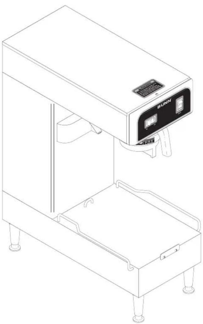
natural_image
Line drawing of a BUNN industrial machine with control panel and base tray (no text or symbols)OPERATING & SERVICE MANUAL
BUNN-O-MATIC CORPORATION
Electrical & Plumbing Requirements ....4
Initial
Adjusting Brew Volumes 6
Auto Sweetener Set-up 6
Operating
Cleaning
Auto Sweetener Cleaning 8
Tea
Troubleshooting
Service
Wiring
2
Notices ....
Set-Up
Controls
8
Brewing
15
Diagrams
INTRODUCTION
This equipment will brew a three-gallon batch of fresh tea into an awaiting dispenser. The tea will be dispensed at approximately room temperature to conserve ice. The brewer is only for indoor use on a sturdy counter or shelf.
BUNN-O-MATIC COMMERCIAL PRODUCT WARRANTY
Bunn-O-Matic Corp. ("BUNN") warrants equipment manufactured by it as follows:
1) All equipment other than as specified below: 2 years parts and 1 year labor.
2) Electronic circuit and/or control boards: parts and labor for 3 years.
3) Compressors on refrigeration equipment: 5 years parts and 1 year labor.
4) Grinding burrs on coffee grinding equipment to grind coffee to meet original factory screen sieve analysis: parts and labor for 3 years or 30,000 pounds of coffee, whichever comes fi rst.
These warranty periods run from the date of installation BUNN warrants that the equipment manufactured by it will be commercially free of defects in material and workmanship existing at the time of manufacture and appearing within the applicable warranty period. This warranty does not apply to any equipment, component or part that was not manufactured by BUNN or that, in BUNN's judgment, has been affected by misuse, neglect, alteration, improper installation or operation, improper maintenance or repair, damage or casualty. This warranty is conditioned on the Buyer 1) giving BUNN prompt notice of any claim to be made under this warranty by telephone at (217) 529-6601 or by writing to Post Office Box 3227, Springfield, Illinois 62708-3227; 2) if requested by BUNN, shipping the defective equipment prepaid to an authorized BUNN service location; and 3) receiving prior authorization from BUNN that the defective equipment is under warranty.
THE FOREGOING WARRANTY IS EXCLUSIVE AND IS IN LIEU OF ANY OTHER WARRANTY, WRITTEN OR ORAL, EXPRESS OR IMPLIED, INCLUDING, BUT NOT LIMITED TO, ANY IMPLIED WARRANTY OF EITHER MERCHANTABILITY OR FITNESS FOR A PARTICULAR PURPOSE. The agents, dealers or employees of BUNN are not authorized to make modifications to this warranty or to make additional warranties that are binding on BUNN. Accordingly, statements by such individuals, whether oral or written, do not constitute warranties and should not be relied upon.
If BUNN determines in its sole discretion that the equipment does not conform to the warranty, BUNN, at its exclusive option while the equipment is under warranty, shall either 1) provide at no charge replacement parts and/or labor (during the applicable parts and labor warranty periods specified above) to repair the defective components, provided that this repair is done by a BUNN Authorized Service Representative; or 2) shall replace the equipment or refund the purchase price for the equipment.
THE BUYER'S REMEDY AGAINST BUNN FOR THE BREACH OF ANY OBLIGATION ARISING OUT OF THE SALE OF THIS EQUIPMENT, WHETHER DERIVED FROM WARRANTY OR OTHERWISE, SHALL BE LIMITED, AT BUNN'S SOLE OPTION AS SPECIFIED HEREIN, TO REPAIR, REPLACEMENT OR REFUND.
In no event shall BUNN be liable for any other damage or loss, including, but not limited to, lost profits, lost sales, loss of use of equipment, claims of Buyer's customers, cost of capital, cost of down time, cost of substitute equipment, facilities or services, or any other special, incidental or consequential damages.
USER NOTICES
Carefully read and follow all notices on the equipment and in this manual. They were written for your protection. All notices on the equipment should be kept in good condition. Replace any unreadable or damaged
00831.0000
WARNING
◆ Fill water tank before turning - on - thermostat or connecting appliance to power source.
◆ Use only on a properly protected circuit capable of the rated load.
◆ Electrically ground the chassis.
◆ Follow national/local electrical codes.
◆ Do not use near combustibles.
FAILURE TO COMPLY RISKS EQUIPMENT DAMAGE, FIRE, OR SHOCK HAZARD
READ THE ENTIRE OPERATING MANUAL BEFORE BUYING OR USING THIS PRODUCT
THIS APPLIANCE IS HEATED WHENEVER CONNECTED TO A POWER SOURCE 00831.0000F 3/98 ©1998 BUNN-O-MATIC CORPORATION
37881.0000
! WARNING
To reduce the risk of electric shock, do not remove or open cover. No user-serviceable parts inside. Authorized service personnel only. Disconnect power before servicing.
03408.0000

WARNING
REMOVE FUNNEL SLOWLY
03409.0000
WARNING
HOT LIQUID
00656.0000
This equipment must be installed to comply with the Basic Plumbing Code of the Building Officials and Code Administrators International, Inc. (BOCA) and the Food Service Sanitation Manual of the Food and Drug Administration (FDA). For models installed out side the U.S.A., comply with the applicable Plumbing/Sanitation Code.
#06064.0000
WARNING
• FILL WATER TANK BEFORE ENERGIZING
• DO NOT OVERLOAD CIRCUIT
- KEEP AWAY FROM COMBUSTIBLES
• DO NOT DEFORM PLUG OR CORD
SEE
INSTRUCTIONS
- FAILURE TO COMPLY RISKS EQUIPMENT DAMAGE, FIRE OR SHOCK
• BREWER ENERGIZED UNLESS UNPLUGGED
32540.0000
BREWERS
TIMER SETTING
CAUTION – Disconnect the power source from the brewer prior to the removal of any panel for the replacement or adjustment of any component.
NOTE: Check that the brewer is connected to water supply, the tank is properly filled, and a funnel and server are in place, prior to setting or modifying batch sizes.
- Modifying batch sizes. To modify a batch volume, first check that the SET/LOCK switch is in the "SET" position on the circuit board. If the brewer has a batch selector switch, position it to the size to be changed.
To increase a batch size, Press and hold the START or BREW switch until three clicks are heard. Release the switch and then press it again one or more times. Each time the switch is pressed, two seconds are added to the brew time period. Allow the brew cycle to finish in order to verify that the desired volume has been achieved.
To decrease a batch size, Press and release the START or BREW switch once for every two-second interval to be removed from the total brew time period; then immediately press and hold down the START or BREW switch until three clicks are heard. Release the switch. Allow the brew cycle to finish in order to verify that the desired volume has been achieved.
- Setting batch sizes. To set a batch volume, first check that the SET/LOCK switch is in the "SET" position on the circuit board. Press and hold the START or BREW switch until three distinct clicks are heard (this will take approximately ten seconds), and then release the switch. (Failure to release the switch within two seconds from the third click causes the volume setting to be aborted). View the level of the liquid being dispensed. When the desired level is reached, turn the ON/OFF switch to "OFF". The brew remembers this volume and will continue to brew batches of this size until the volume setting procedure is repeated. Empty server(s), turn selector switch to positions that have yet to be set, and repeat batch settling procedure until all batch sizes are set.
NOTE: When brewing coffee, batch volumes will decrease due to absorption by the coffee grounds.
32540.0000C 09/01 ©1999 Bunn-O-Matic Corporation
ELECTRICAL REQUIREMENTS
CAUTION - The brewer must be disconnected from the power source until specified in Initial Set-Up.
120V model brewers require 2-wire, grounded service rated 120 volts ac, 15 amp, single phase, 60 Hz.
"A" model brewers require 2-wire, grounded service rated 230 volts ac, 10 amp, single phase, 50 Hz.
"B" model brewers require 2-wire, grounded service rated 100 volts ac, 15 amp, single phase, 60 Hz.
WARNING - If the power cord is ever damaged, it must be replaced by the manufacturer or its service agent with a special cord available from the manufacturer or its service agent in order to avoid a hazard.
Proceed as follows:
Electrical Hook-Up
CAUTION – Improper electrical installation will damage electronic components.
- An electrician must provide electrical service as specified.
- Using a voltmeter, check the voltage and color coding of each conductor at the electrical source.
- Remove top cover from the brewer.
- Rotate the control thermostat knob fully counterclockwise to the "OFF" position and replace the top cover.
- Connect the brewer to the power source.
- If plumbing is to be hooked up later be sure the brewer is disconnected from the power source. If plumbing has been hooked up, the brewer is ready for Initial Set-Up.
PLUMBING REQUIREMENTS
These brewers must be connected to a cold water system with operating pressure between 20 (138) and 90 psi (620 kPa) from a 12 " or larger supply line. A shut-off valve should be installed in the line before the brewer. Install a regulator in the line when pressure is greater than 90 psi (620 kPa) to reduce it to 50 psi (345 kPa). The water inlet fi tting is 14 " fl are.
NOTE - Bunn-O-Matic recommends 14 " copper tubing for installations of less than 25 feet and 38 " for more than 25 feet from the 12 " water supply line. A tight coil of copper tubing in the water line will facilitate moving the brewer to clean the countertop. Bunn-O-Matic does not recommend the use of a saddle valve to install the brewer. The size and shape of the hole made in the supply line by this type of device may restrict water flow.
This equipment must be installed to comply with the Basic Plumbing Code of the Building Officials and Code Administrators International, Inc. (BOCA) and the Food Service Sanitation Manual of the Food and Drug Administration (FDA). For models installed outside the U.S.A., you must comply with the applicable Plumbing/Sanitation Code for your area.
- Remove the shipping cap from the bulkhead fi tting on the rear of the brewer.
- Flush the water line and securely attach it to the bulkhead fitting on the rear of the brewer.
- Turn on the water supply.
NOTE: TheFlow Control/Strainer assembly is internal, located inside the back panel.
INITIAL SET-UP
CAUTION - The brewer must be disconnected from the power source throughout the initial set-up, except when specified in the instructions.
- Remove the top lid from the brewer.
- Rotate the control thermostat knob fully counterclockwise to the "OFF" position and replace the top lid.
- Set the delay knob of the timer on the right side of the hood at eight minutes and the dilution knob of the timer on the right side of the hood at three minutes and forty-fi ve seconds.
- Remove the metal discharge tip from the funnel to speed up the set-up procedure. Insert the empty funnel into the funnel rails.
- Place an empty dispenser on the brewer base. Be sure the funnel discharge is directly above the hole in the dispenser top lid.
-
Plug in the brewer and place the ON/OFF switch in the "ON" position. Momentarily press the start switch. Water will flow into the tank and will shut off after three minutes. Press the start switch again. During the second period, the tank will fill to its capacity and the excess will flow from the funnel into the dispenser.
-
Place the ON/OFF switch in the "OFF" position.
-
Disconnect the brewer from the power source and remove the top lid.
-
Rotate the control thermostat knob fully clockwise to the "ON" position and replace the top lid.
-
Plug in the brewer and wait for the water in the tank to heat to the proper temperature (approximately 20 minutes). Some water will drip from the funnel during this time; this is due to expansion and should not occur thereafter.
-
Place an empty dispenser under the funnel.
-
Place the ON/OFF switch in the "ON" position and press the start switch. Empty the dispenser after water has stopped flowing from the funnel.
-
Allow the water in the tank to reheat to the proper temperature.
-
Place the ON/OFF switch in the "ON" position and press the start switch.
-
Place the ON/OFF switch in the "OFF" position immediately after water stops flowing from the funnel. Check the water volume in the dispenser. It should be seventy-six ounces.
-
If not, unplug the brewer, remove the top lid, and adjust the timer on the left side of the hood as required. See Adjusting Brew Volumes. Replace the top lid, plug in the brewer, start, and measure another concentrate cycle.
-
Repeat steps 13-16 until the proper water volume is achieved.
-
Unplug the brewer and remove the top lid.
-
Set the delay knob of the timer on the right side of the hood at three minutes and empty the dispenser.
-
Place the ON/OFF switch in the "ON" position, momentarily press the start switch, and allow both the concentrate and dilution cycles to occur.
| Brew water temperature is factory set at 200°F (93.3°C) Areas of high altitude will require lowering this tempera-ture to prevent boiling. This chart should be used as a guide when readjusting the brew water temperature. | ||||
| Altitude(Feet) | Boiling point of water | Recommended water temperature | ||
| °F | °C | °F | °C | |
| -1000 | 213.8 | 101.0 | 200 | 93.3 |
| -500 | 212.9 | 100.5 | 200 | 93.3 |
| 0 | 212.0 | 100.0 | 200 | 93.3 |
| 500 | 211.1 | 99.5 | 200 | 93.3 |
| 1000 | 210.2 | 99.0 | 200 | 93.3 |
| 1500 | 209.3 | 98.5 | 200 | 93.3 |
| 2000 | 208.4 | 98.0 | 200 | 93.3 |
| 2500 | 207.4 | 97.4 | 200 | 93.3 |
| 3000 | 206.5 | 96.9 | 199 | 92.8 |
| 3500 | 205.6 | 96.4 | 198 | 92.2 |
| 4000 | 204.7 | 95.9 | 197 | 91.7 |
| 4500 | 203.8 | 95.4 | 196 | 91.1 |
| 5000 | 202.9 | 94.9 | 195 | 90.6 |
| 5500 | 201.9 | 94.4 | 195 | 90.6 |
| 6000 | 201.0 | 93.9 | 194 | 90.0 |
| 6500 | 200.1 | 93.4 | 193 | 89.4 |
| 7000 | 199.2 | 92.9 | 192 | 88.9 |
| 7500 | 198.3 | 92.4 | 191 | 88.3 |
| 8000 | 197.4 | 91.9 | 190 | 87.8 |
| 8500 | 196.5 | 91.4 | 189 | 87.2 |
| 9000 | 195.5 | 90.8 | 188 | 86.7 |
| 9500 | 194.6 | 90.3 | 187 | 86.1 |
| 10000 | 193.7 | 89.8 | 186 | 85.6 |
INITIAL SET-UP (cont.)
- When all water stops flowing, check the water volume in the dispenser. It should be 396 ounces.
- If not, unplug the brewer and remove the top lid.
- Adjust the dilution knob of the timer on the right side of the hood as required. Replace the top lid, plug in the brewer, start, and measure another brew cycle.
- Repeat steps 20-23 until the proper water volume is achieved.
- Return the delay knob of the timer on the right side of the hood to eight minutes. Replace the top lid and plug in the brewer.
- Reinstall the metal discharge tip into the funnel.
- Load the funnel with a BUNN® paper fi iter and approximately four ounces of loose tea leaves.
- Place the ON/OFF switch in the "ON" position, momentarily press the start switch, and allow both the concentrate and dilution cycles to occur. Observe the funnel discharge and the dilution streams near the end of the brew cycle. The dilution stream should stop approximately thirty seconds after the funnel discharge has stopped.
- If not, unplug the brewer and remove the top lid.
- Adjust the delay knob of the timer on the right side of the hood as required. Replace the top lid and plug in the brewer.
- Repeat steps 27-30 until the proper dilution timing is achieved.
ADJUSTING BREW VOLUMES
CAUTION - Disconnect the power source from the brewer prior to the removal of any panel for the replacement or adjustment of any component.
NOTE: Prior to setting or modifying batch sizes, check that the brewer is connected to water supply, the tank is properly filled, and a funnel and server are in place.
- Modifying batch sizes. To modify a batch volume, first check that the SET/LOCK switch is in the "SET" position on the circuit board.
To increase a batch size. Press and hold the START or BREW switch until three clicks are heard. Release the switch (Failure to release the switch within two seconds after the third click causes the volume setting to be aborted and previous volume setting will remain in memory) and press it again one or more times. Each time the switch is pressed, two seconds are added to the brew time period. Allow the brew cycle to finish in order to verify that the desired volume has been achieved.
To decrease a batch size. Press and release the START or BREW switch once for every two-second interval to be removed from the total brew time period; then immediately press and hold down the START or BREW switch until three clicks are heard. Release the switch. (Failure to release the switch within two seconds after the third click causes the volume setting to be aborted and previous volume setting will remain in memory). Allow the brew cycle to finish in order to verify that the desired volume has been achieved.
- Setting batch sizes. To set a batch volume, first check that the SET/LOCK switch is in the "SET" position on the circuit board. Press and hold the START or BREW switch until three distinct clicks are heard, and then release the switch. (Failure to release the switch within two seconds after the third click causes the volume setting to be aborted and previous volume setting will remain in memory). View the level of the liquid being dispensed. When the desired level is reached, turn the ON/OFF switch to "OFF" (lower). The brewer remembers this volume and will continue to brew batches of this size until the volume setting procedure is repeated.
NOTE: When brewing tea, batch volumes will decrease due to absorption by the tea grounds.
- Setting programming disable feature. If it becomes necessary to prevent anyone from changing brew times once programmed, you can set the SET/LOCK switch to the "LOCK" position. This will prevent any programming to be done until switch is once again placed in the "SET" position.
AUTO SWEETENER SET-UP
CAUTION - The brewer must be disconnected from the power source throughout the Initial Set-Up, except when specified in the instructions.
- Remove the top lid and rear panel.
- Make sure the brewer water supply is off.
- Connect sweetener hose from the bag in a box delivery system to the rear fi tting marked "Sweetener"
IMPORTANT - System delivery pressure must be regulated between 30-40 psi. System also needs to deliver product for at least 4 minutes without shutting off. Some pump systems shut off after a few minutes of continuous running.
- Set the "Delay knob on the dilution timer to the 3 minute setting. (The minimum delay setting)
- Plug brewer into the power source.
- Place an empty reservoir under the dilution nozzle of the brewer.
- Close the adjustment valve on the rear of the brewer fully (clockwise), then open (counterclockwise) 1/2 turn.
- Set the selector switch to the "Sweetened" side and press the "Start" switch momentarily. (After approximately 3 minutes the sweetener will come out of the dilution nozzle.)
- Run sweetener for 1 minute, then set selector switch to the "Off" position. The flow will stop.
- Measure the amount of sweetener dispensed and calculate if the volume needs to be increased or decreased (Dilution cycle is usually between 3 to 3 1/2 minutes).
- If adjustment is needed, turning the adjustment valve clockwise decreases the amount of sweetener dispensed and turning the adjustment valve counterclockwise increases the amount of sweetener dispensed.
- Set the "Delay" knob on the dilution timer back to the 6 to 7 minute setting.
- After the desired volume has been set, turn the water supply on.
- Reinstall the top lid and rear panel.
The brewer may now be returned to service.
OPERATING CONTROLS
A. ON/OFF Switch
ON - Placing the switch in the left position allows the start switch to activate a timed brew cycle for three gallons of tea.
OFF - Placing the switch in the right position stops the brew cycle. Stopping a brew cycle after it has been started will not stop the flow of water into the funnel until the tank syphons down to its proper level. The switch should always be placed in this position after a brew cycle and whenever the brewer is unattended.
B. Start Switch
Starts a brew cycle when the ON/OFF switch is in the "ON" position.
C. UNSWEET/OFF/SWEET Selector Switch (Models with Sweetener Only)
UNSWEET - Placing the switch in the left positional allows the start switch to activate a timed brew cycle for three gallons of tea without sweetener.
OFF - Placing the switch in the middle position stops the brew cycle. Stopping a brew cycle after it has been started will not stop the flow of water into the funnel until the tank syphons down to its proper level. The switch should always be placed in this position after a brew cycle and whenever the brewer is unattended.
SWEET - Placing the switch in the right positional allows the start switch to activate a timed brew cycle for three gallons of tea with sweetener.
CLEANING
CAUTION - CLEAN AND SANITIZE YOUR ICED TEA BREWER DAILY
- Remove and thoroughly clean the entire brew funnel. The funnel tip and screen must be free from any tea particles or residue. Reassemble the funnel.
- Place the ON/OFF switch in the "OFF" position. Remove and thoroughly rinse the sprayhead. The holes must be open and clear of any mineral deposits. Wipe the sprayhead panel clean with a damp cloth.
- Insert the deliming spring into the sprayhead fi tting until no more than two inches is visible and move it in and out 5 or 6 times. Insert the spring into the airvent hole in the sprayhead panel and move it in and out 5 or 6 times. Reattach the sprayhead.
- Wash the entire outside surface of the brewer with a clean damp cloth.
CAUTION - DO NOT KEEP BREWED ICED TEA OVERNIGHT. THE SERVER MUST BE CLEANED DAILY.
AUTO SWEETENER CLEANING
- Remove the connector off of the bag in a box.
- Place the end in a bucket of hot water (120°-130°F)
- Place an empty reservoir on the base under the dilution nozzle.
- Set the selector switch to the "Sweetened" setting.
- Press and release the "Start" switch.
- Run three brew cycles in a row, emptying the reservoir after each cycle.
- When the three cycles have been completed, hook the connector back up to the bag in a box system. (This will keep buildup from occurring in the system.)
This procedure should be performed weekly or as needed to keep the system clear.
TEA BREWING
- Begin each brew cycle with a clean empty brew funnel and server. (Be sure the server lid doesn't interfere with the flow of dilution water.)
- Insert a BUNNi Iter into the funnel.
- Pour the packet of loose fresh tea leaves into the fi Iter. Approximately four ounces is recommended.
- Level the bed of tea leaves by gently shaking.
- Slide the funnel into the funnel rails until it stops.
- Place the ON/OFF switch in the "ON" position.
- Momentarily press the start switch.
CAUTION - The funnel contains hot liquids. Remove funnel slowly.
- Carefully remove the brew funnel and discard the used filter when tea no longer drips from the funnel tip.
- Place the ON/OFF switch in the "OFF" position to prevent a false start.
- Fresh tea is available at the faucet.
TROUBLESHOOTING
A troubleshooting guide is provided to suggest probable causes and remedies for the most likely problems encountered. If the problem remains after exhausting the troubleshooting steps, contact the Bunn-O-Matic Technical Service Department.
- Inspection, testing, and repair of electrical equipment should be performed only by qualified service personnel.
- All electronic components have 120 - 240 volt ac and low voltage dc potential on their terminals. Shorting of terminals or the application of external voltages may result in board failure.
- Intermittent operation of electronic circuit boards is unlikely. Board failure will normally be permanent. If an intermittent condition is encountered, the cause will likely be a switch contact or a loose connection at a terminal or crimp.
- Solenoid removal requires interrupting the water supply to the valve. Damage may result if solenoids are energized for more than ten minutes without a supply of water.
- The use of two wrenches is recommended whenever plumbing fittings are tightened or loosened. This will help to avoid twists and kinks in the tubing.
- Make certain that all plumbing connections are sealed and electrical connections tight and isolated.
- This brewer is heated at all times. Keep away from combustibles.
WARNING -
• Exercise extreme caution when servicing electrical equipment.
- Unplug the brewer when servicing, except when electrical tests are specified.
- Follow recommended service procedures
- Replace all protective shields or safety notices
| Problem | Probable Cause | Remedy |
| Brew cycle will not start | 1. No water | Water lines and valves to the brewer must be open. |
| 2. No power or incorrect voltage to the brewer | Check circuit breakers or fuses. | |
| 3. Strainer/Flow Control (.750GPM) | (A) Direction of flow arrow must be pointing upwards in the brewer. | |
| (B) Remove the strainer/flow control and check for obstructions. Clear or replace. | ||
| PROBLEM | PROBABLE CAUSE | REMEDY |
| Brew cycle will not start (cont.) | 4. ON/OFF Switch | Refer to Service - ON/OFF Switch for testing. See page 24 |
| 5. Start Switch | Refer to Service - Start Switch for testing procedures. See page 23 | |
| 6. Brew Timer | Refer to Service - Brew Timer for testing procedures. See page 18 | |
| 7. Brew Solenoid Valve | Refer to Service - Brew Solenoid Valve for testing procedures. See page 16 | |
| 8. Internal Flow control (.195 GPM) | (A) Direction of flow arrow must be pointing towards check valve.(B) Remove the flow control and check for obstructions. Clear or replace. | |
| Water is not hot | 1. Limit ThermostatCAUTION- Do not eliminate or bypass limit thermostat or thermal cut-off. Use only BOM replacement part 29329.0001 | Refer to Service - Limit Thermostat for testing procedures. See page 22 |
| 2. Control Thermostat | Refer to Service - Control Thermostat for testing procedures. See page 17 | |
| 3. Tank Heater | Refer to Service - Tank Heater for testing procedures. See page 27 | |
| Dilution cycle will not start | 1. ON/OFF Switch | Refer to Service - ON/OFF Switch for testing procedures. See page 24 |
| 2. Start Switch | Refer to Service - Start Switch for testing procedures. See page 23 | |
| 3. Dilution Timer | Refer to Service - Dilution Timer for testing procedures. See page 21 | |
| Dilution cycle will not start (cont.) | 4. Dilution Solenoid Valve | Refer to Service - Dilution Solenoid Valve for testing procedures. See page 20 |
| Inconsistent beverage level in dispenser | 1. Internal Flow Control (.195 GPM) | (A) Direction of flow arrow must be pointing towards the check valve.(B) Remove the flow control and check for obstruction. Clear or replace. |
| 2. Syphon System | The brewer must be level or slightly lower in front to syphon properly. | |
| 3. Lime Build-upCAUTION - Tank and tank components should be delimed regularly depending on local water conditions. Excessive mineral build-up on stainless steel surfaces can initiate corrosive reactions resulting in serious leaks. | Inspect the tank assembly for excessive lime deposits. Delime as required. | |
| 4. Water Pressure | The water pressure to the brewer must be at least 20 psi (138 kPa). | |
| Consistently high or low beverage level in the dispenser | 1. Brew Timer/Delay Timer | With the ON/OFF switch "ON" adjust the brew timer to achieve the recommended 76 oz. of concentrate then the dilution timer to achieve a total of 396 oz. for each three-gallon brew cycle. |
| 2. Strainer/Flow Control (.750GPM) | (A) Direction of flow arrow must be pointing upwards in the brewer.(B) Remove the strainer/flow control and check for obstructions. Clear or replace. |
TROUBLESHOOTING (cont.) PROBLEM
| Spitting or excessive steaming | 1. Lime Build-upCAUTION - Tank and tank components should be delimed regularly depending on local water conditions. Excessive mineral build-up on stainless steel surfaces can initiate corrosive reactions resulting in serious leaks. | Inspect tank assembly for excessive lime deposits. Delime as required. |
| 2. Control Thermostat | Refer to Service - Control Thermostat for testing procedures. See page 17 | |
| Drip-out time too long | 1. Funnel Tip | The brew funnel should be cleaned thoroughly before each brew cycle to lessen the chance of tea leaf particles clogging the drip-out tip. |
| Dripping from sprayhead | 1. Syphon System | The brewer must be level or slightly lower in front to syphon properly. |
| 2. Lime Build-upCAUTION - Tank and tank components should be delimed regularly depending on local water conditions. Excessive mineral build-up on stainless steel surfaces can initiate corrosive reactions resulting in serious leaks. | Inspect the tank assembly for excessive lime deposits. Delime as required. | |
| 3. Brew Solenoid Valve | Refer to Service - Brew Solenoid Valve for testing procedures. See page 16 | |
| Water flows into tank continuously (ON/OFF Switch "ON") or (UNSWEET/OFF/SWEET Switch in "UNSWEET" or "SWEET" position) | 1. Brew Timer | Refer to Service - Brew Timer for testing procedures. See page 18 |
| Water flows into tank continuously (ON/OFF Switch "OFF") or (UNSWEET/OFF/SWEET Switch in "OFF" position) | 1. Brew Solenoid Valve | Refer to Service - Brew Solenoid Valve for testing procedures. See page 16 |
TROUBLESHOOTING (cont.) PROBLEM
| Beverage overfl ows dispenser | 1. Dispenser | The dispenser must be completely empty before starting a brew cycle. |
| 2. Brew Timer | Refer to Service - Brew Timer for testing procedures. See page 18 | |
| 3. Brew Solenoid Valve | Remove the Brew Solenoid Valve and clean any obstruction. Rebuild or replace the valve if necessary. See page 16 | |
| 4. Dilution Timer | Refer to Service - Dilution Timer for testing procedures. See page 21 | |
| 5. Dilution Solenoid Valve | Refer to Service - Dilution Solenoid Valve for testing procedures. See page 20 | |
| Weak beverage | 1. Filter Type | BUNN® paper fi Iters must be used for proper extraction. |
| 2. Tea | A suffi cient quantity of fresh, loose tea leaves should be used for proper extraction. | |
| 3. Sprayhead | A clean stainless steel sprayhead must be used for proper extraction. | |
| 4. Funnel Loading | The BUNN® paper fi Iter must be centered in the funnel and the bed of tea leaves leveled by gentle shaking. | |
| 5. Water Temperature | Place an empty funnel on an empty dispenser beneath the sprayhead. Initiate a brew cycle and check the water temperature immediately below the sprayhead with a thermometer. The reading should not be less than 200°F (93°C). Adjust the control thermostat to increase the water temperature. Replace if necessary. | |
| PROBLEM | PROBABLE CAUSE | REMEDY |
| Dry tea leaves remain in the funnel | 1. Funnel Loading | The BUNN® paper fi Iter must be centered in the funnel and the bed of grounds leveled by gently shaking. |
| Brewer is making unusual noises | 1. Solenoid(s) | The nut on the solenoid(s) must be tight or it will vibrate during operation. |
| 2. Plumbing Lines | Plumbing lines should not be resting on the counter top. | |
| 3. Water Supply | (A) The brewer must be connected to a cold water line.(B) Water pressure to the brewer must not exceed 90 psi (620 kPa). Install a regulator if necessary to lower the working pressure to approximately 50 psi (345 kPa). | |
| 4. Tank Heater | Remove and clean lime off the tank heater. See page 27 | |
| Sweetener is not working | 1. Sweetener box is empty | Check the Sweetener box to make sure it is not out of product. |
| 2. Flow Adjustment screw is closed | Check the Flow Adjustment screw to make sure the valve has not closed. | |
| 3. Solenoid is defective | Refer to Service -Sweetener Solenoid Valve for testing procedures. See page 26 | |
| 4. The Pump is defective | Check the manufacturers warranty for additional information on testing and replacement of a defective pump. |
SERVICE
This section provides procedures for testing and replacing various major components used in this brewer should service become necessary. Refer to Troubleshooting for assistance in determining the cause of any problem.
WARNING - Inspection, testing, and repair of electrical equipment should be performed only by qualified service personnel. The brewer should be disconnected from the power source when servicing, except when electrical tests are required and the test procedure specifically states to plug in the brewer.
COMPONENT ACCESS
WARNING - Disconnect the brewer from the power source before the removal of any panel or the replacement of any component.
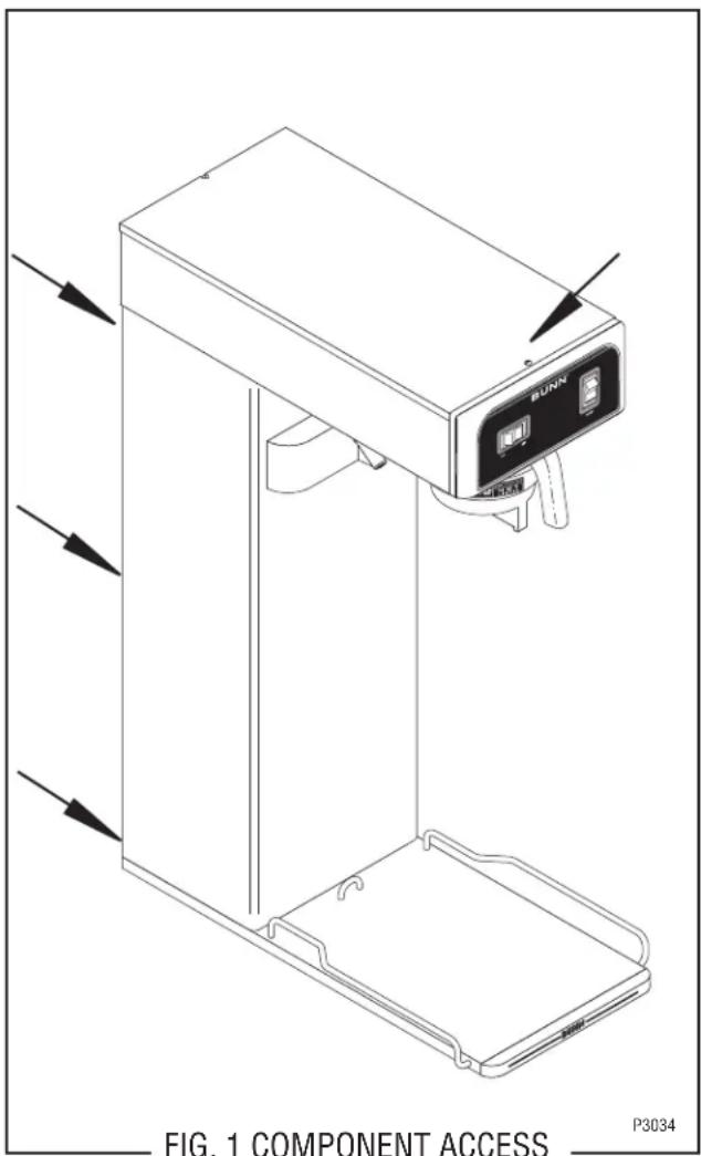
All components are accessible by the removal of the top cover and rear inspection panel.
The top cover is attached with one #6-32 screw. Removal of the top cover will allow access to ON/OFF switch, start switch, brew timer, dilution timer, control thermostat, limit thermostat and tank heater,
The rear inspection panel is attached with six #8-32 screws. Removal of the rear panel will allow access to the brew solenoid valve, dilution solenoid valve and the sweetener solenoid valve (optional), .195 GPM & .750 GPM flow control and check valves.
Contents
Brew Solenoid Valve 16
Control Thermostat 17
Digital Brew Timer....18
Dilution Timer 20
Dilution Solenoid Valve 21
Limit Thermostat 22
Start Switch 23
ON/OFF Switch 24
UNSWEET/OFF/SWEET Switch 25
Sweetner Solenoid 26
Tank Heater 27
Wiring Diagrams 28
SERVICE (cont.)
BREW SOLENOID VALVE
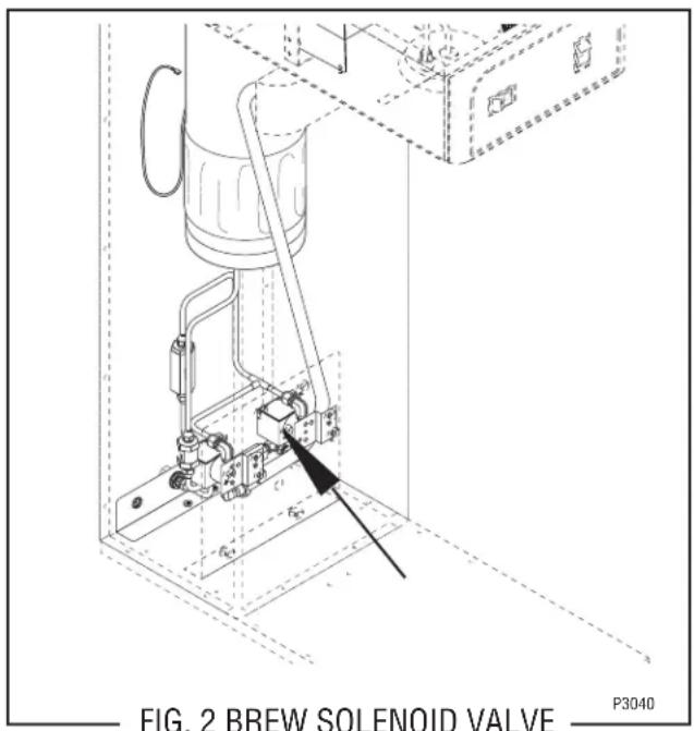
Location:
Viewing the brewer from the rear the brew sole-noid valve is mounted on the left side of the mounting bracket.
Test Procedures:
- Disconnect the brewer from the power source.
- Disconnect the white/violet and white/green wires from the solenoid valve. With the ON/OFF switch in the "ON" upper position press the start switch.
-
With a voltmeter, check the voltage across the white/violet and white/green wires. Connect the brewer to the power source. The indication must be:
a) 120 volts ac for two wire 120 volt models.
b) 230 volts ac for two wire 230 volt models.
c) 100 volts ac for two wire 100 volt models. -
Disconnect the brewer from the power source,
If voltage is present as described, proceed to #5 If voltage is not present as described, refer to Wiring Diagrams and check brewer wiring harness.
- Check for continuity across the solenoid valve coil terminals.
If continuity is present as described, reconnect the white/violet from the ON/OFF switch and white/green wire from the brew timer.
If continuity is not present as described, replace the solenoid valve.
-
Check the solenoid valve for coil action. Connect the brewer to the power source. With ON/OFF switch in the "ON" upper position press start switch and listen carefully in the vicinity of the solenoid valve for a "clicking" sound as the coil magnet attracts.
-
Disconnect the brewer from the power source.
If the sound is heard as described and water will not pass through the solenoid valve, there may be a blockage in the water line before the solenoid valve or, the solenoid valve may require inspection for wear, and removal of waterborne particles.
If the sound is not heard as described, replace the solenoid valve.
Removal and Replacement:
- Remove all wires from solenoid valves.
- Turn off the water supply to the brewer.
- Disconnect the water lines to and from the sole-noid valves.
- Remove the two #8-32 keps nuts holding the mounting bracket to the brewer base.
- Lift out the bracket.
- Remove the two #10-32 slotted-head screws holding the solenoid valve to the mounting bracket.
- Securely install the new solenoid valve to the mounting bracket.
- Attach the mounting bracket to the brewer base.
- Securely fasten the water lines to and from the solenoid valves.
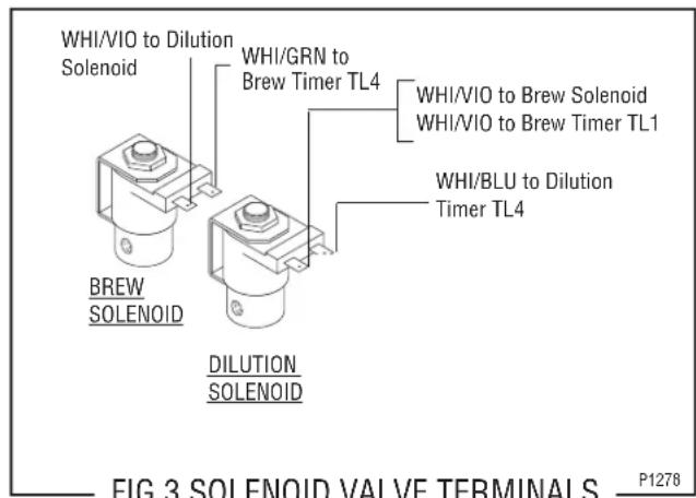
- Refer to the Fig.3 when reconnecting the wires
SERVICE (cont.)
CONTROL THERMOSTAT
Location:
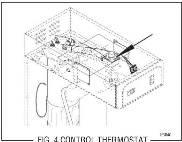
The control thermostat is located inside hood on the right side just behind the dilution timer.
Test Procedures:
- Disconnect the brewer from the power source.
- Locate the blue/black wire on the control thermostat.
- With a voltmeter, check the voltage across the blue/black wire on the control thermostat and the white wire on the tank heater for 100 volt and 120 volt two wire models or red wire on the tank heater for 230 volt two wire models. Connect the brewer to the power source. The indication must be:
a) 120 volts ac for two wire 120 volt models.
b) 230 volts ac for two wire 230 volt models.
c) 100 volts ac for two wire 100 volt models. - Disconnect the brewer from the power source.
If voltage is present as described, proceed to #5.
If voltage is not present as described, refer to the Wiring Diagrams and check the brewer wiring harness.
-
Locate the black wire on the control thermostat.
-
Gently remove the capillary bulb and grommet from the tank.
-
With a voltmeter, check the voltage across the black wire of the control thermostat and the white wire on the tank heater for 100 volt and 120 volt two wire models or red wire on the tank heater for 230 volt two wire models when the control
thermostat is turned fully clockwise. Connect the brewer to the power source. The indication must be:
a) 120 volts ac for two wire 120 volt models.
b) 230 volts ac for two wire 230 volt models.
c) 100 volts ac for two wire 100 volt models.
- Disconnect the brewer from the power source.
If voltage is present as described, reinstall the capillary tube into the tank to the line 4.5" above the bulb, the control thermostat is operating properly.
If voltage is not present as described, replace the thermostat.
Removal and Replacement:
- Remove both wires from the control thermostat terminals.
- Remove the thermostat capillary bulb by firmly pulling up on the capillary tube at the tank lid. This will disengage the grommet from the tank lid.
- Remove the #8-32 screw holding the control thermostat to its bracket.
- Slide the grommet to the line 4.5" above the bulb on the new capillary tube.
- Insert the capillary bulb through the hole in the tank lid and press the grommet fi rmly and evenly so that the groove in the grommet fi ts into the tank lid.
- Carefully bend the capillary tube so that the tube and bulb inside the tank are in a vertical position.
NOTE – The capillary tube must be clear of any electrical termination and not kinked.
- Fasten the new control thermostat to its bracket.
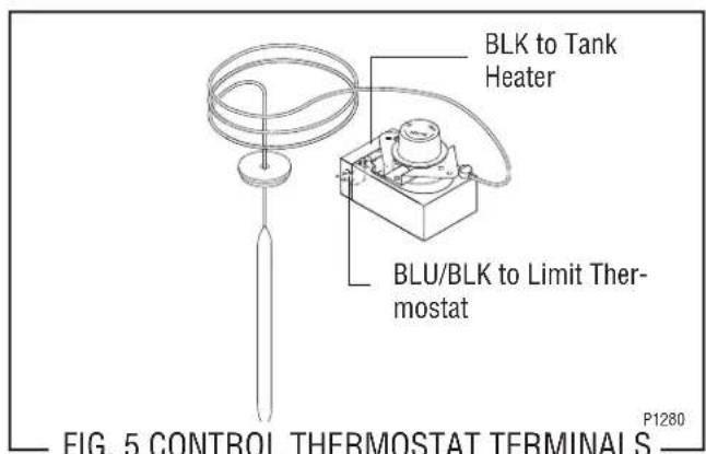
- Refer to Fig. 5 when reconnecting the wires.
- Adjust the control thermostat as required.
SERVICE (cont.)
DIGITAL BREW TIMER
Location:
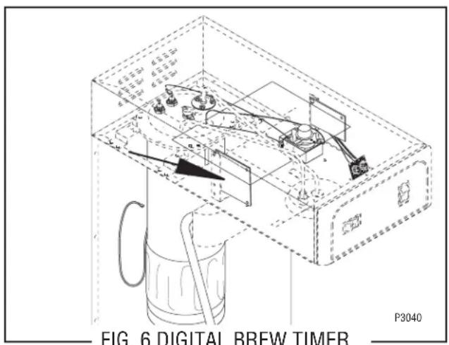
The timer is located in the hood, on the left side.
Test Procedure:.
NOTE: Do not remove or install wires while timer board is installed. Pressure applied to one side may cause damage to the board.
- Disconnect the brewer from the power source and remove the front access panel.
- Remove the two #8-32 screws securing circuit board to the mounting bracket.
- Remove circuit board and spacers (as required).
- With a voltmeter, check the voltage across terminals TL1 and TL2 when the "ON/OFF" switch is in the "ON" position. Connect the brewer to the power source. The indication must be:
a) 120 volts ac for two wire 120 volt models.
b) 230 volts ac for two wire 230 volt models.
c) 100 volts ac for two wire 100 volt models.
- Disconnect the brewer from the power source.
If voltage is present as described, proceed to #6. If voltage is not present as described, refer to the Wiring Diagrams and check the brewer wiring harness.
- With a voltmeter, check the voltage across terminals TL1 and TL4 when the "ON/OFF" switch is in the "ON" position. Connect the brewer to the power source. The indication must be 0 volts.
If voltage is as described, proceed to #7.
If voltage is not as described, disconnect the brewer from the power source and replace the timer.
- With a voltmeter, check the voltage across terminals TL1 and TL4 when the "ON/OFF" switch is in the "ON" position. Connect the brewer to the power source and press the "START" switch. The indication must be as follows:
a) 120 volts ac for two wire 120 volt models.
b) 230 volts ac for two wire 230 volt models.
c) 100 volts ac for two wire 100 volt models.
If voltage is present as described, the brew timer is operating properly. Reset the timer as required, to obtain the desired brew volume.
If voltage is not present as described, disconnect the brewer from the power source and replace the timer.
Removal and Replacement:
- Remove the two #8-32 screws securing circuit board to the hood.
- Remove circuit board and spacers (as required).
- Remove all wires from the timer.
- Attach all wires to the replacement timer board prior to installation to the component mounting bracket. Refer to FIG. 7 when reconnecting the wires.
- Install new circuit board with spacers (as required) to the component mounting bracket.
- Adjust the timer as described below.
Timer Setting:
NOTE: Prior to setting or modifying volumes, check that the brewer is connected to water supply, the tank is properly filled, and a funnel and server are in place.
NOTE: All volume settings must be done with the sprayhead installed.
- Modifying brew volumes. To modify a brew volume, first check that the SET/LOCK switch is in the "SET" position on the circuit board.
SERVICE (cont.)
DIGITAL BREW TIMER (cont.)
To increase a brew volume, place the ON/OFF switch in the "ON" position, press and hold the START switch until three clicks are heard. Release the switch and press it again one or more times. (Failure to release the switch within two seconds after the third click causes the volume setting to be aborted and previous volume setting will remain in memory.) Each time the switch is pressed, two seconds are added to the brew time period. Allow the brew cycle to finish in order to verify that the desired volume has been achieved.
To decrease a brew volume, place the ON/OFF switch in the "ON" position, press and release the START switch once for every two-second interval to be removed from the total brew time period; then immediately press and hold down the START switch until three clicks are heard. Release the switch. (Failure to release the switch within two seconds after the third click causes the volume setting to be aborted and previous volume setting will remain in memory). Allow the brew cycle to finish in order to verify that the desired volume has been achieved.
- Setting brew volumes. To set a brew volume, first check that the SET/LOCK switch is in the "SET" position on the circuit board. Place the ON/OFF switch in the "ON" position, press and hold the START switch until three distinct clicks are heard and then release the switch. (Failure to release the switch within two seconds after the third click causes the volume setting to be aborted and previous volume setting will remain in memory.)
View the level of the liquid being dispensed. When the desired level is reached, turn the ON/OFF switch to "OFF".
NOTE: Several ounces of water will continue to syphon from the tank after turning the switch "OFF". The brewer remembers this volume and will continue to brew batches of this size until the volume setting procedure is repeated.
NOTE: When brewing tea, volume will decrease due to absorption by the tea grounds.
- Setting programming disable feature. If it becomes necessary to prevent anyone from changing brew time once programmed, you can set the SET/LOCK switch to the "LOCK" position. This will prevent any further programming until switch is once again put into the "SET" position.
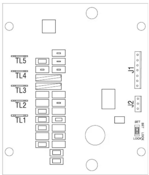
TL1 - WHI/VIO to Dilution Timer and WHI/VIO to ON/OFF Switch
TL2 - WHI to Power Cord (100V & 120V) or RED to Power connector (230V) and WHI to Dilution Timer (100V & 120V) or RED to Dilution Timer (230V)
TL3 - WHI/ORN to Start Switch
TL4 - WHI/GRN to Brew Solenoid
TL5 - WHI/YEL to Start Switch
P2037
FIG. 7 DIGITAL TIMER WIRING
SERVICE (cont.)
DILUTION SOLENOID VALVE
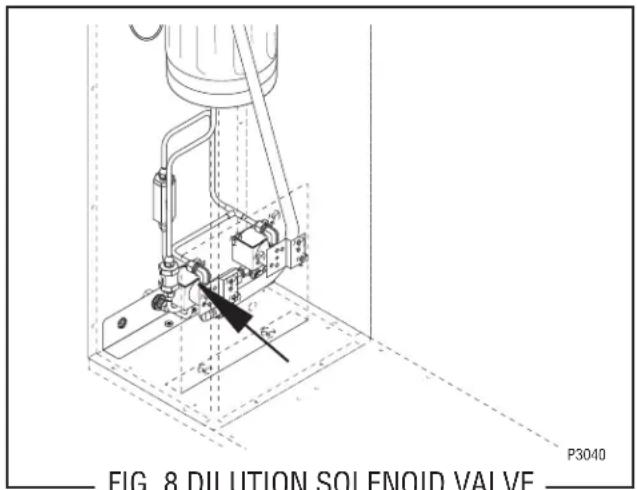
Location:
Viewing the brewer from the rear the dilution sole-noid is mounted on the center of the solenoid mounting bracket which is secured to the trunk base.
Test Procedure:
- Disconnect the brewer from the power source.
- With a voltmeter, check the voltage across the white/blue and white/violet wires on the dilution solenoid terminals when the ON/OFF switch is in the "ON" position and the start switch is momentarily placed in the lower position. Connect the brewer to the power source. After the approximate setting on the delay dial, the indication must be:
a) 120 volts ac for two wire 120 volt models.
b) 230 volts ac for two wire 230 volt models.
c) 100 volts ac for two wire 100 volt models, remain for the approximate setting on the dilution dial, and then return to its previous indication. - Disconnect the brewer from the power supply.
If voltage is present as described, proceed to #4. If voltage is not present as described, refer to the Wiring Diagrams and check the wiring harness.
- Remove both wires from the coil and check for continuity across the coil terminals.
If continuity is present as described, reconnect the white/blue and white/violet wires and proceed to #5. If continuity is not present as described, replace the solenoid valve.
- Check the solenoid valve for coil action. Connect
the brewer to the power source, place the ON/OFF switch in the "ON" position and momentarily place the start switch in the lower position and release. Listen carefully after the approximate setting on the delay dial in the vicinity of the solenoid valve for a "clicking" sound as the coil magnet attracts and after the approximate setting on the dilution dial, repels the plunger.
- Disconnect the brewer from the power source.
If the sound is heard as described and water will not pass through the solenoid valve, there may be a blockage in the water line before or after the solenoid valve or, the solenoid valve may require inspection for wear, and removal of waterborne particles.
If the sound is not heard as described, replace the solenoid valve.
Removal and Replacement:
- Remove all wires from the solenoid valves.
- Turn off the water supply to the brewer.
- Disconnect the water lines to and from the sole-noid valves.
- Remove the two 8-32 keps nuts holding the mounting bracket to the trunk base.
- Lift out the bracket.
- Remove the two 10-32 slotted-head screws holding the solenoid valve to the mounting bracket.
- Securely install the new solenoid valve to the mounting bracket.
- Attach the mounting bracket to the trunk base.
- Securely fasten the water lines to and from the solenoid valves.
- Refer to Fig. 9 when reconnecting the wires.
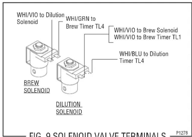
FIG. 9 SOLENOID VALVE TERMINALS
P1278
SERVICE (cont.)
DILUTION TIMER
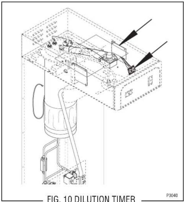
Location:
The dilution timer is located inside the hood on the right side. It consists of the dial plate with two dials and circuit board.
Test Procedure:
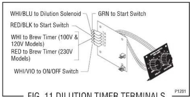
- Disconnect the brewer from the power source and remove the wires from terminals TL3, TL4, & TL5 of the timer and rotate both dials fully counterclockwise.
- With a voltmeter, check the voltage across terminals TL1 and TL2 when the ON/OFF switch is in the "ON" position. Connect the brewer to the power source. The indication must be:
a) 120 volts ac for two wire 120 volt models.
b) 230 volts ac for two wire 230 volt models.
c) 100 volts ac for two wire 100 volt models.
- Disconnect the brewer from the power source.
If voltage is present as described, proceed to #4.
If voltage is not present as described, refer to the Wiring Diagrams and check the wiring harness.
- Check for continuity across the green and red/black wires when the start switch is held in the lower position.
If continuity is present as described, reconnect the wires to terminals TL3, TL4, & TL5 of the timer board and proceed to #5.
If continuity is not present as described, refer to the Wiring Diagrams and check the wiring harness.
- With a voltmeter, check the voltage across terminals TL1 and TL4 when the ON/OFF switch is in the "ON" position and the start switch is momentarily placed in the lower position. Connect the brewer to the power source. After a delay of approximately three minutes, the indication must be:
a) 120 volts ac for two wire 120 volt models for approximately one minute and then return to its previous indication.
b) 230 volts ac for two wire 230 volt models for approximately one minute and then return to its previous indication.
c) 100 volts ac for two wire 100 volt models for approximately one minute and then return to its previous indication.
- Disconnect the brewer from the power source.
If voltage is present as described, the timer is operating properly. Adjust the timer dials as required.
If voltage is not present as described, replace the timer.
Removal and Replacement:
- Remove all wires from the timer.
- Remove the circuit board and dial plate from the brackets.
- Install the new dial plate and circuit board to the brackets.
- Refer to Fig. 11 when reconnecting the wires.
- Adjust the timer dials as required.
SERVICE (cont.)
LIMIT THERMOSTAT
Location:
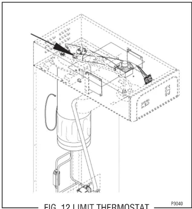
The limit thermostat is located inside the hood on the tank lid.
Test Procedure:
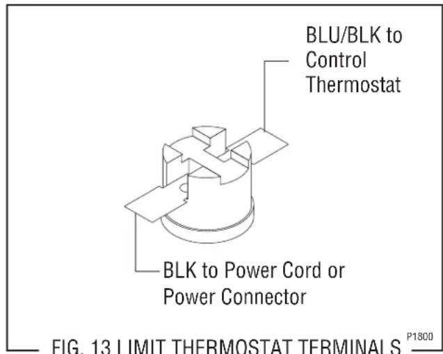
- Disconnect the brewer from the power source and remove the black wire from the limit thermostat.
- With a voltmeter, check the voltage across the black wire removed from the limit thermostat and the white wire or red wire on the tank heater terminal. Connect the brewer to the power source. The indication must be:
a) 120 volts ac for two wire 120 volt models.
b) 230 volts ac for two wire 230 volt models.
c) 100 volts ac for two wire 100 volt models.
- Disconnect the brewer from the power source.
If voltage is present as described, reconnect the black wire and proceed to #4.
If voltage is not present as described, refer to the Wiring Diagrams and check the wiring harness.
-
Remove the blue/black wire from the limit thermostat.
-
With a voltmeter, check the voltage across the exposed terminal of the limit thermostat and the white wire from the power cord or the red wire from the power connector. Connect the brewer to the power source. The indication must be:
a) 120 volts ac for two wire 120 volt models.
b) 230 volts ac for two wire 230 volt models.
c) 100 volts ac for two wire 100 volt models.
- Disconnect the brewer from the power source.
If voltage is present as described, reconnect the blue/black wire to the limit thermostat. The limit thermostat is operating properly.
If voltage is not present as described, replace the limit thermostat.
Removal and Replacement
- Remove both wires from the limit thermostat terminals.
- Carefully slide the limit thermostat out from under the retaining clip.
- Carefully slide the new limit thermostat into the retaining clip.
- Refer to Fig. 13 when reconnecting the wires.
SERVICE (cont.)
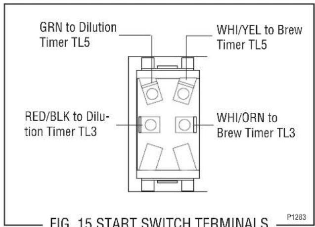
START SWITCH
Location:
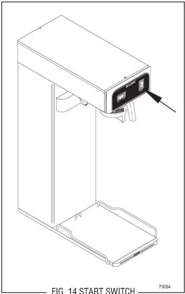
The start switch is located in the front of the hood, above and to the right of the brew funnel.
Test Procedure:
- Disconnect the brewer from the power source.
- Remove the wires from all four terminals.
- Check for continuity across the two terminals on the right side of the switch when it is held in the lower position. Continuity must not be present across these terminals in the upper position.
If continuity is present as described, proceed to #4. If continuity is not present as described, replace the switch.
- Check for continuity across the two terminals on the left side of the switch when it is held in the lower position. Continuity must not be present across these terminals in the upper position.
If continuity is present as described, reconnect the wires, the switch is operating properly.
If continuity is not present as described, replace the switch.
Removal and Replacement:
- Remove the wires from the switch terminals.
- Compress the clips inside the hood and gently push the switch through the opening.
- Push the new switch into the opening and spread the clips to hold the switch captive in the hood.
- Refer to Fig. 15 when reconnecting the wires.
SERVICE (cont.)
ON/OFF SWITCH
Location:
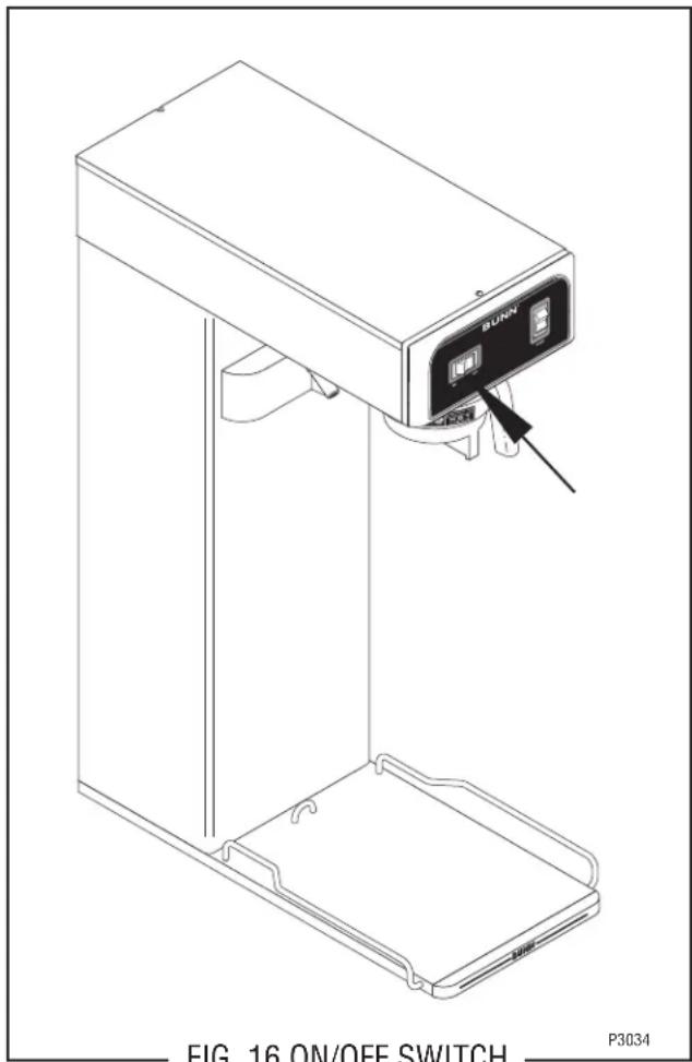
The ON/OFF switch is located in the front of the hood, above and to the left of the brew funnel.
Test Procedure:
Brewers W/Out Half Batch Option
- Disconnect the brewer from the power source.
- Remove the black and white/violet wires from the switch terminals.
- With a voltmeter, check the voltage across the black wire removed from the ON/OFF switch and the white wire remaining on the switch terminal.
- Connect the brewer to the power source. The indication must be:
a) 120 volts ac for two wire 120 volt models.
b) 230 volts ac for two wire 230 volt models.
c) 100 volts ac for two wire 100 volt models.
- Disconnect the brewer from the power source.
If voltage is present as described, proceed to #6. If voltage is not present as described, refer to the Wiring Diagrams and check the wiring harness.
- Check for continuity across the center and end terminals of the top row when the switch is in the "ON" position.
If continuity is present as described, replace the wires, the switch is operating properly.
If continuity is not present as described, replace the switch.
Removal and Replacement:
- Remove the wires from the switch terminals.
- Compress the clips inside the hood and gently push the switch through the opening.
- Push the new switch into the opening and spread the clips to hold the switch captive in the hood.
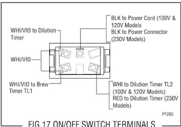
- Refer to FIG. 17 when reconnecting the wires.
SERVICE (cont.)
UNSWEET/OFF/SWEET SWITCH (Sweetner Option)
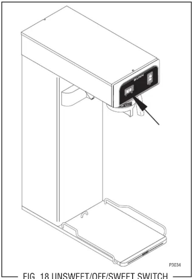
FIG. 18 UNSWEET/OFF/SWEET SWITCH
Location:
The UNSWEET/OFF/SWEET switch is located in the front of the hood, above and to the left of the brew funnel.
Test Procedure:
- Disconnect the brewer from the power source.
- With a voltmeter, check the voltage across the black wire and white wire on the selector switch.
- Connect the brewer to the power source. The indication must be:
a) 120 volts ac for two wire 120 volt models.
b) 230 volts ac for two wire 230 volt models.
c) 100 volts ac for two wire 100 volt models. - Disconnect the brewer from the power source.
If voltage is present as described, proceed to #5. If voltage is not present as described, refer to the Wiring Diagrams and check the wiring harness.
- Disconnect the black and white wires from the center terminals.
- Disconnect the brown/white and white/violet wires from the right side terminals.
- Check for continuity across the center and right terminals in rows one through four when the switch is in the "SWEET" position.
If continuity is present as described, replace the wires on the right side and proceed to #8.
If continuity is not present as described, replace the switch.
- Disconnect the white/violet wires on the left side terminal.
- Check for continuity across the center and left side terminals in rows one through four when the switch is in the "UNSWEET" position.
If continuity is present as described, replace the wires the switch is operating properly.
If continuity is not present as described, replace the switch.
Removal and Replacement:
- Remove the wires from the switch terminals.
- Compress the clips inside the hood and gently push the switch through the opening.
- Push the new switch into the opening and spread the clips to hold the switch captive in the hood.
- Refer to FIG. 19 when reconnecting the wires.
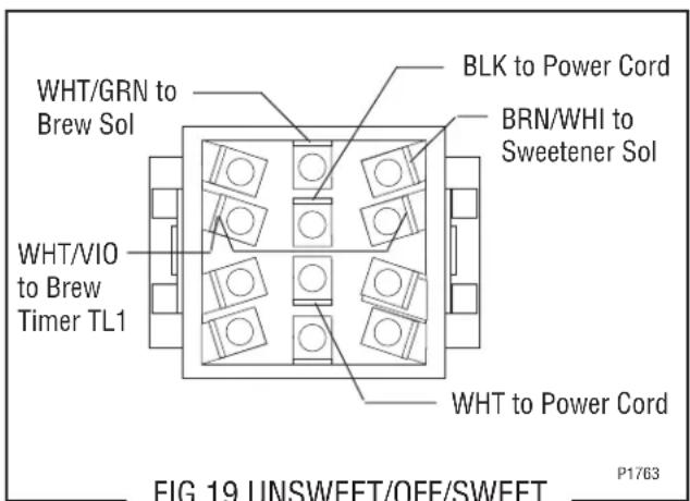
FIG.19 UNSWEET/OFF/SWEET SWITCH TERMINALS
P1763
SERVICE (cont.)
SWEETNER SOLENOID VALVE
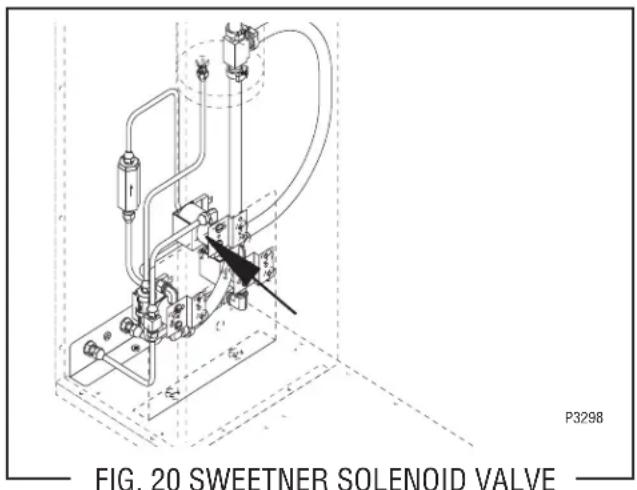
Location:
Viewing the brewer from the front, the sweetener solenoid is mounted on the right side of the solenoid mounting bracket which is secured to the bottom base housing.
Test Procedure:
- Disconnect the brewer from the power source.
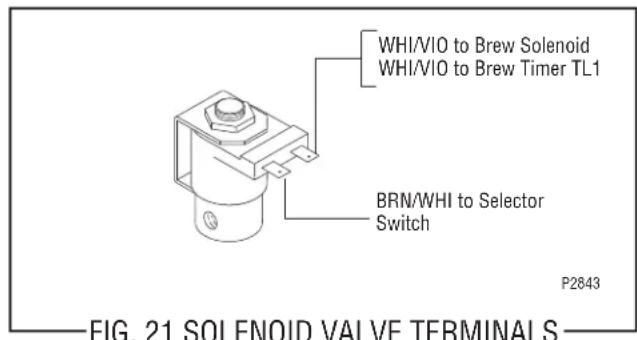
- With a voltmeter, check the voltage across the brown/white and white/violet wires on the sweetener solenoid terminals when the UNSWEET/OFF/SWEET switch is in the "SWEET" position and the start switch is momentarily placed in the lower position. Connect the brewer to the power source. After the approximate setting on the delay dial, the indication must be:
a) 120 volts ac for two wire 120 volt models.
b) 230 volts ac for two wire 230 volt models.
c) 100 volts ac for two wire 100 volt models, remain for the approximate setting on the dilution dial, and then return to its previous indication.
- Disconnect the brewer from the power supply.
If voltage is present as described, proceed to #4. If voltage is not present as described, refer to the Wiring Diagrams and check the wiring harness.
- Remove both wires from the coil and check for continuity across the coil terminals. If continuity is present as described, reconnect the brown/white and white/violet wires and proceed to #5.
If continuity is not present as described, replace the solenoid valve.
-
Check the solenoid valve for coil action. Connect the brewer to the power source, place the UNSWEET/OFF/SWEET switch in the "SWEET" position and momentarily place the start switch in the lower position and release. At the start of a brew cycle, listen carefully in the vicinity of the solenoid valve for a "clicking" sound as the coil magnet attracts and at the end of the brew cycle when the plunger is released.
-
Disconnect the brewer from the power source.
If the sound is heard as described and sweetener will not pass through the solenoid valve, there may be a blockage in the sweetener line before or after the solenoid valve or, the solenoid valve may require inspection for wear, and removal of particles.
If the sound is not heard as described, replace the solenoid valve.
Removal and Replacement:
- Remove all wires from the solenoid valves.
- Turn off the sweetener supply to the brewer.
- Disconnect the water lines to and from the sole-noid valves.
- Remove the two #8-32 keps nuts holding the solenoid bracket to the mounting bracket.
- Lift out the valve and bracket.
- Remove the two #10-32 slotted-head screws holding the solenoid valve to the mounting bracket.
- Securely install the new solenoid valve to the mounting bracket.
- Attach the solenoid valve and bracket to the mounting bracket.
- Securely fasten the sweetener and water lines to and from the solenoid valves.
- Refer to Fig. 19 when reconnecting the wires.
SERVICE (cont.)
TANK HEATER
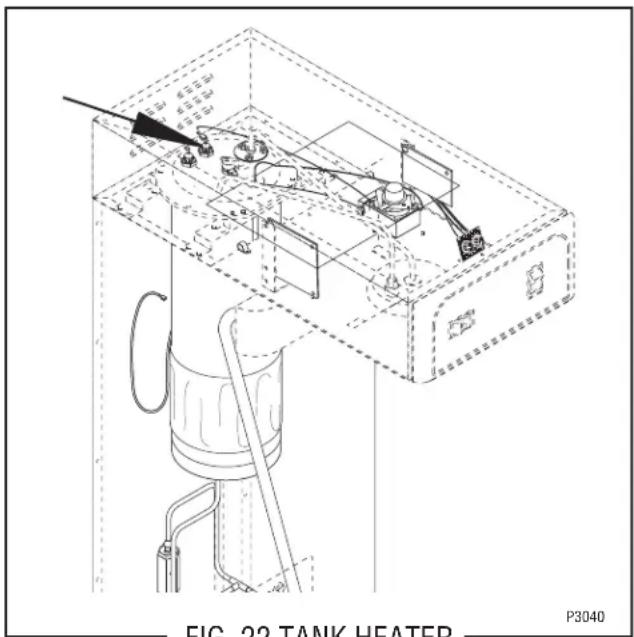
FIG. 22 TANK HEATER
Location:
The tank heater is located inside the tank and secured to the tank lid.
Test Procedures:
- Disconnect the brewer from the power supply.
- With a voltmeter, check the voltage across the black and white wires on 100 volt and 120 volt models or the black and red wires for 230 volt models. Connect the brew to the power source. The indication must be:
a) 120 volts ac for two wire 120 volt models.
b) 230 volts ac for two wire 230 volt models. c) 100 volts ac for two wire 100 volt models.
-
Disconnect the brewer from the power source. If voltage is present as described, proceed to #4 If voltage is not present as described, refer to the Wiring Diagrams and check wiring harness.
-
Disconnect the black wire and the white wire or red wire from the tank heater terminals.
- Check for continuity across the tank heater terminals.
If continuity is present as described, reconnect the wires, the tank heater is operating properly. If continuity is not present as described, replace the tank heater.
NOTE- If the tank heater remains unable to heat, remove and inspect heater for cracks in the sheath.
Removal and Replacement:
- Disconnect the black wire and the white or red wire from the tank heater terminals.
- Remove sprayhead and the hex nut securing the sprayhead tube to the hood. Set aside for reassembly.
- Disconnect vent tube.
- Remove the six #10 thread cutting screws securing the tank lid to the tank.
- Remove the tank lid with limit thermostat, sprayhead tube, tank heater and vent tube.
- Remove the two hex nuts securing the tank heater to the tank lid. Remove tank heater with gaskets and discard.
- Install new tank heater with gaskets on the tank lid and secure with two hex nuts.
- Install tank lid with limit thermostat, sprayhead tube, tank heater and vent tube using six #10 thread cutting screws.
- Secure sprayhead tube to hood using a hex nut.
- Install sprayhead.
- Connect vent tube to fitting.
- Reconnect the wires to the limit thermostat, tank heater. See limit thermostat section in this manual when reconnecting wires.
- Refer to Fig. 23 when reconnecting the tank heater wires.
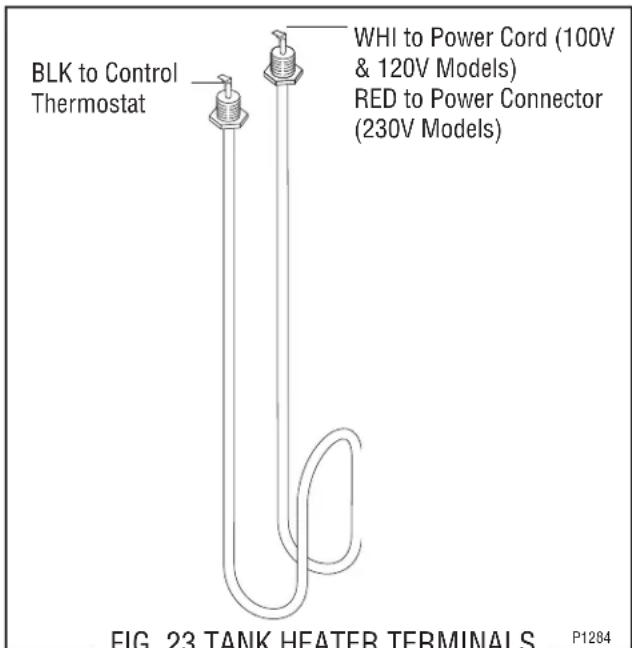
FIG. 23 TANK HEATER TERMINALS
P1284
SCHEMATIC WIRING DIAGRAM TB3, TB3B, TB3-LP
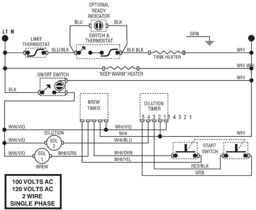
flowchart
graph TD
    A["L1 N"] --> B["LIMIT THERMOSTAT"]
    B --> C["BLU/BLK"]
    C --> D["OPTIONAL READY INDICATOR"]
    D --> E["SWITCH & THERMOSTAT"]
    E --> F["BLK BLK"]
    F --> G["TANK HEATER"]
    G --> H["GRN"]
    H --> I["WHI"]
    J["ON/OFF SWITCH"] --> K["BLK"]
    K --> L["BREW TIMER"]
    L --> M["DILUTION TIMER"]
    M --> N["WHI/VIO"]
    M --> O["WHI/BLU"]
    M --> P["WHI/ORN"]
    M --> Q["WHI/YEL"]
    R["WHI/VIO"] --> S["DILUTION SOL 2"]
    S --> T["WHI/GRN"]
    U["WHI/VIO"] --> V["SOL 1"]
    V --> W["BREW"]
    X["START SWITCH"] --> Y["RED/BLK GRN"]
    Y --> Z["WHI"]
    style A fill:#f9f,stroke:#333
    style J fill:#f9f,stroke:#333
    style R fill:#f9f,stroke:#333
    style U fill:#f9f,stroke:#333
    style X fill:#f9f,stroke:#333
    style Z fill:#f9f,stroke:#333
SCHEMATIC WIRING DIAGRAM
TU3, TB3 W/SWEETENER
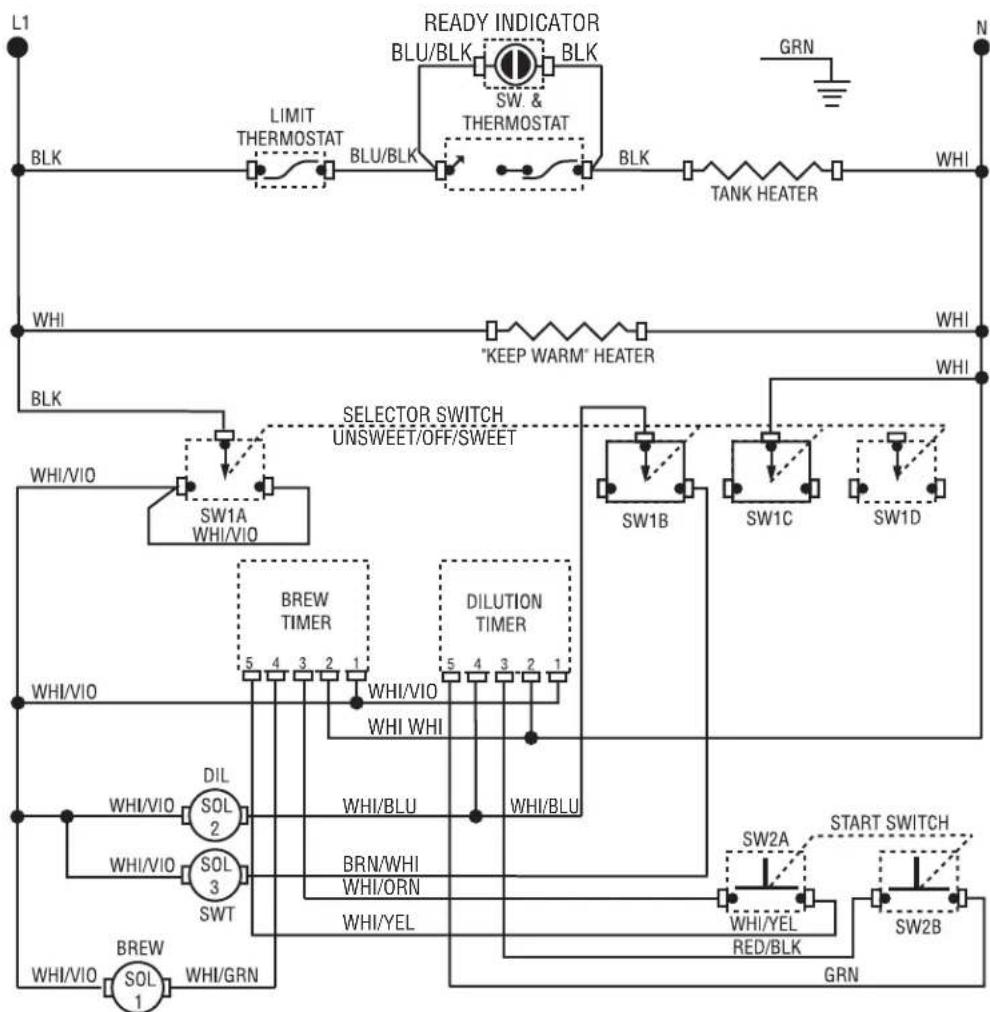
flowchart
graph TD
    subgraph Power Source
        L1 --> BLK
        BLK --> LIMIT_THERMOSTAT
        LIMIT_THERMOSTAT --> BLU_BLK
        BLU_BLK --> READY_INDICATOR
        READY_INDICATOR --> BLU_BLK
        BLU_BLK --> BLK
        BLK --> TANK_HEATER
        TANK_HEATER --> WHI
    end

    subgraph Power Supply
        BLK --> WHI
        BLK --> "KEEP WARM"_HEATER
        WHI --> WHI_VIO
        WHI --> SW1A_WHI/VIO
        SW1A_WHI/VIO --> BLEW_TIMER
        SW1A_WHI/VIO --> WHI_VIO
        WHI_VIO --> WHI_VIO
        WHI_VIO --> WHI_VIO
        WHI_VIO --> WHI_VIO
        WHI_VIO --> WHI_VIO
        WHI_VIO --> WHI_VIO
        WHI_VIO --> WHI_VIO
        WHI_VIO --> WHI_VIO
        WHI_VIO --> WHI_VIO
        WHI_VIO --> WHI_VIO
        WHI_VCOOLING_SOL_POL_SOL_WT_BREW_BREW
        WHI_VCOOLING_SOL_POL_SOL_WT_BREW_BREW
        WHI_VCOOLING_SOL_POL_SOL_WT_BREW_BREW
    end

    subgraph Control Inputs
        RLCK["RLCK"] --> BLU_BLK
        BLU_BLK --> BLU_BLK
        BLU_BLK --> BLK
        BLK --> TANK_HEATER
        TANK_HEATER --> WHI
    end

    subgraph External Controls
        SW1B["SW1B"] --> BLEW_TIMER
        SW1C["SW1C"] --> BLEW_TIMER
        SW1D["SW1D"] --> BLEW_TIMER
        BLEW_TIMER --> WHI_VIO
        BLEW_TIMER --> WHI_VIO
        BLEW_TIMER --> WHI_VIO
        BLEW_TIMER --> WHI_VIO
        BLEW_TIMER --> WHI_VIO
        BLEW_TIMER --> WHI_VIO
        BLEW_TIMER --> WHI_VIO
        BLEW_TIMER --> WHI_VIO
        BLEW_TIMER --> WHI_VIO
        BLEW_TIMER --> WHI_VIO
        BLEW_TIMER --> WHI_VEO
        BLEW_TIMER --> WHI_VEO
        BLEW_TIMER --> WHI_VEO
        BLEW_TIMER --> WHI_VEO
        BLEW_TIMER --> WHI_VEO
        BLEW_TIMER --> WHI_VEO
        BLEW_TIMER --> WHI_VEO
        BLEW_TIMER --> WHI_VEO
        BLEW_TIMER --> WHI_VEO
        BLEW_TIMER --> WHI_VEO
        BLEW_TIMER --> WHI_VELOLELED_BLK_BLK_BLK_BLK_BLK_BLK_BLK_BLK_BLK_BLK_BLK_BLK_BLK_BLK_BLK_BLK_BLK_BLK_BLK_BLK_BLK_BLK_BLK_BLK_BLK_BLK_BLK_BLK_BLK_BLK_BLK_BLK_BLK_BLK_BLK_BLK_BLK_BLK_BLK_BLK_BLK_BLK_BLK_BLK_BLK_BLK_BLK_BLK_BLK_BLK_BRK_BRK_BRK_BRK_BRK_BRK_BRK_BRK_BRK_BRK_BRK_BRK_BRK_BRK_BRK_BRK_BRK_BRK_BRK_BRK_BRK_BRK_BRK_BRK_BRK_BRK_BRK_BRK_BRK_BRK_BRK_BRK_BRK_BRK_BRK_BRK_BRK_BRK_BRK_BRK_BRK_BRK_BRK_BRK_BRK_BRK_BRK_BRK_BRK_BRK_BLK_BLK_BLK_BLK_CLRB_WLHLHLHLHLHLHLHLHLHLHLHLHLHLHLHLHLHLHLHLHLHLHLHLHLHLHLHLHLHLHLHLHLHLHLHLHLHLHLHLHLHLHLHLHLHLHLHLHLHLHLHLHLHLHLHLHLHLHLHLHLHLHLHLHLHLHLHLHLHLHLHLHLHLHLHLHLHLHLHLHLHLHLHLHLHLHLHLHLHLHLHLHLHLHLHLHLHLHLHLHLHDLWGNDGNDGNDGNDGNDGNDGNDGNDGNDGNDGNDGNDGNDGNDGNDGNDGNDGNDGNDGNDGNDGNDGNDGNDGNDGNDGNDGNDGNDGNDGNDGNDGNDGNDGNDGNDGNDGNDGNDGNDGNDGNDGNDGNDGNDGNDGNDGNDGNDGNDGND GNDGNDGNDGNDGNDGNDGNDGNDGNDGNDGNDGNDGNDGNDGNDGNDGNDGNDGNDGNDGNDGNDGNDGNDGNDGNDGNDGNDGNDGNDGNDGNDGNDGNDGNDGNDGNDGNDGNDGNDGNDGNDGNDGNDGNDGNDGNDGNDGNDGNDVLDWGNDWGNDWGNDWGNDWGNDWGNDWGNDWGNDWGNDWGNDWGNDWGNDWGNDWGNDWGNDWGNDWGNDWGNDWGNDWGNDWGNDWGNDWGNDWGNDWGNDWGNDWGNDWGNDWGNDWGNDWGNDWGNDWGNDWGNDWGNDWGNDWGNDWGNDWGNDWGNDWGNDWGNDWGNDWGNDWGNDWGNDWGNDWGNDWGNDWGNDWGNCDDGDNGDGDNGDGDNGDGDNGDGDNGDGDNGDGDNGDGDNGDGDNGDGDNGDGDNGDGDNGDGDNGDGDNGDGDNGDGDNGDGDNGDGDNGDGDNGDGDNGDGDNGDGDNGDGDNGDGDNGDGDNGDGDNGDGDNGDGDNGDGDNGDGDNGDGDNGDGDNGDGDNGDGDNGDGTDDGDNGDGDNGDGDNGDGDNGDGDNGDGDNGDGDNGDGDNGDGDNGDGDNGDGDNGDGDNGDGDNGDGDNGDGDNGDGDNGDGDNGDGDNGDGDNGDGDNGDGDNGDGDNGDGDNGDGDNGDGDNGDGDNGDGDNGDGDNGDGDNGDGDNGDGDNGDGDNGDGDNGTDDGDNGTDDGDNGTDDGDNGTDDGDNGTDDGDNGTDDGDNGTDDGDNGTDDGDNGTDDGDNGTDDGDNGTDDGDNGTDDGDNGTDDGDNGTDDGDNGTDDGDNGTDDGDNGTDDGDNGTDDGDNGTDDGDNGTDDGDNGTDDGDNGTDDGDNGTDDGDNGTDDGDNGTDDGDNGTTCDDGTDDGTDDGTDDGTDDGTDDGTDDGTDDGTDDGTDDGTDDGTDDGTDDGTDDGTDDGTDDGTDDGTDDGTDDGTDDGTDDGTDDGTDDGTDDGTDDGTDDGTDDGTDDGTDDGTDDGTDDGTDDGTDDGTDDGTDDGTDDGTDDGTDDGTDDGTDDGTDDGTDDGTDDGTDDGTDDGTDDGTDDGTDDGTDDGTDDGTDDTGTTTTTTTTTTTTTTTTTTTTTTTTTTTTTTTTTTTTTTTTTTTTTTTTTTTTTTTTTTTTTTTTTTTTTTTTTTTTTTTTTTTTTTTTTTTTTTTTTTTTTTTTTTTTTTTTTTTTTTTTTTTTTTTTTTTTTTTTTTTTTTTTTTTTTTTTTTTTTTTTTTTTTTTTTTTTTTTTTTTTTTTTTTTTTTTTTTTGDTGTTCCTCGCTCGCTCGCTCGCTCGCTCGCTCGCTCGCTCGCTCGCTCGCTCGCTCGCTCGCTCGCTCGCTCGCTCGCTCGCTCGCTCGCTCGCTCGCTCGCTCGCTCGCTCGCTCGCTCGCTCGCTCGCTCGCTCGCTCGCTCGCTCGCTCGCTCGCTCGCTCGCTCGCTCGCTCGCTCGCTCGCTCGCTCGCTCGCTCGCTCGCTCCCTCGCTCGCTCGCTCGCTCGCTCGCTCGCTCGCTCGCTCGCTCGCTCGCTCGCTCGCTCGCTCGCTCGCTCGCTCGCTCGCTCGCTCGCTCGCTCGCTCGCTCGCTCGCTCGCTCGCTCGCTCGCTCGCTCGCTCGCTCGCTCGCTCGCTCGCTCGCTCGCTCGCTCGCTCGCTCGCTCGCTCGCTCGCTCGCTCGCTCSSTCCSTCCSTCCSTCCSTCCSTCCSTCCSTCCSTCCSTCCSTCCSTCCSTCCSTCCSTCCSTCCSTCCSTCCSTCCSTCCSTCCSTCCSTCCSTCCSTCCSTCCSTCCSTCCSTCCSTCCSTCCSTCCSTCCSTCCSTCCSTCCSTCCSTCCSTCCSTCCSTCCSTCCSTCCSTCCSTCCSTCCSTCCSTCCSTCCSTCCSTCCCATTCCCATTCCCATTCCCATTCCCATTCCCATTCCCATTCCCATTCCCATTCCCATTCCCATTCCCATTCCCATTCCCATTCCCATTCCCATTCCCATTCCCATTCCCATTCCCATTCCCATTCCCATTCCCATTCCCATTCCCATTCCCATTCCCATTCCCATTCCCATTCCCATTCCCATTCCCATTCCCATTCCCATTCCCATTCCCATTCCCATTCCCATTCCCATTCCCATTCCCATTCCCATTCCCATTCCCATTCCCATTCCCATTCCCATTCCCATTCCCATTCCCATTCCCATCCCCATCCCCATCCCCATCCCCATCCCCATCCCCATCCCCATCCCCATCCCCATCCCCATCCCCATCCCCATCCCCATCCCCATCCCCATCCCCATCCCCATCCCCATCCCCATCCCCATCCCCATCCCCATCCCCATCCCCATCCCCATCCCCATCCCCATCCCCATCCCCATCCCCATCCCCATCCCCATCCCCATCCCCATCCCCATCCCCATCCCCATCCCCATCCCCATCCCCATCCCCATCCCCATCCCCATCCCCATCCCCATCCCCATCCCCATCCCCATCCCCATCCCCATCCCCCCATCCCCATCCCCATCCCCATCCCCATCCCCATCCCCATCCCCATCCCCATCCCCATCCCCATCCCCATCCCCATCCCCATCCCCATCCCCATCCCCATCCCCATCCCCATCCCCATCCCCATCCCCATCCCCATCCCCATCCCCATCCCCATCCCCATCCCCATCCCCATCCCCATCCCCATCCCCATCCCCATCCCCATCCCCATCCCCATCCCCATCCCCATCCCCATCCCCATCCCCATCCCCATCCCCATCCCCATCCCCATCCCCATCCCCATCCCCATCCCCCATCCCCATAACCATCAACCATCAACCATCAACCATCAACCATCAACCATCAACCATCAACCATCAACCATCAACCATCAACCATCAACCATCAACCATCAACCATCAACCATCAACCATCAACCATCAACCATCAACCATCAACCATCAACCATCAACCATCAACCATCAACCATCAACCATCAACCATCAACCATCAACCATCAACCATCAACCATCAACCATCAACCATCAACCATCAACCATCAAGCAGCAGCAGCAGCAGCAGCAGCAGCAGCAGCAGCAGCAGCAGCAGCAGCAGCAGCAGCAGCAGCAGCAGCAGCAGCAGCAGCAGCAGCAGCAGCAGCAGCAGCAGCAGCAGCAGCAGCAGCAGCAGCAGCAGCAGCAGCAGCAGCAGCAGAACCACCACCACCACCACCACCACCACCACCACCACCACCACCACCACCACCACCACCACCACCACCACCACCACCACCACCACCACCACCACCACCACCACCACCACCACCACCACCACCACCACCACCACCACCACCACCACCACCACCACCACCACCACCACCACCACCACCACCACCACCACCACCACCACCACCACCACCACCACCACCACCACCACCACCACCACCACCACCACCACCACCACCACCACCACCACCACCACCACCACCACAAACAAACAAACAAACAAACAAACAAACAAACAAACAAACAAACAAACAAACAAACAAACAAACAAACAAACAAACAAACAAACAAACAAACAAACAAACAAACAAACAAACAAACAAACAAACAAACAAACAAACAAACAAACAAACAAACAAACAAACAAACAAACAAACAAACAAACAAACAAACAAACAAACAAACAAAUCACAAUCACAAUCACAAUCACAAUCACAAUCACAAUCACAAUCACAAUCACAAUCACAAUCACAAUCACAAUCACAAUCACAAUCACAAUCACAAUCACAAUCACAAUCACAAUCACAAUCACAAUCACAAUCACAAUCACAAUCACAAUCACAAUCACAAUCACAAUCACAAUCACAAUCACAAUCACAUCACAUCACAUCACAUCACAUCACAUCACAUCACAUCACAUCACAUCACAUCACAUCACAUCACAUCACAUCACAUCACAUCACAUCACAUCACAUCACAUCACAUCACAUCACAUCACAUCACAUCACAUCACAUCACAUCACAUCACAUCACAUCACAUCACAUCACAUCACAUCACAUCACAUCACAUCACAUCACAUCACAUCACAUCACAUCACAUCACAUCACAUCACAUCACAUCACAUCACTAUGAUGAUGAUGAUGAUGAUGAUGAUGAUGAUGAUGAUGAUGAUGAUGAUGAUGAUGAUGAUGAUGAUGAUGAUGAUGAUGAUGAUGAUGAUGAUGAUGAUGAUGAUGAUGAUGAUGAUGAUGAUGAUGAUGAUGAUGAUGAUGAUGAUGAUGC BWC BWC BWC BWC BWC BWC BWC BWC BWC BWC BWC BWC BWC BWC BWC BWC BWC BWC BWC BWC BWC BWC BWC BWC BWC BWC BWC BWC BWC BWC BWC BWC BWC BWC BWC BWC BWC BWC BWC BWC BWC BWC BWC BWC BWC BWC BWC BWC BWC BWC BWP CWP CWP CWP CWP CWP CWP CWP CWP CWP CWP CWP CWP CWP CWP CWP CWP CWP CWP CWP CWP CWP CWP CWP CWP CWP CWP CWP CWP CWP CWP CWP CWP CWP CWP CWP CWP CWP CWP CWP CWP CWP CWP CWP CWP CWP CWP CWP CWP CWP CWP CCNDCNDCNDCNDCNDCNDCNDCNDCNDCNDCNDCNDCNDCNDCNDCNDCNDCNDCNDCNDCNDCNDCNDCNDCNDCNDCNDCNDCNDCNDCNDCNDCNDCNDCNDCNDCNDCNDCNDCNDCNDCNDCNDCNDCNDCNDCNDCNDCNDCNDCNOCNDCNDCNDCNDCNDCNDCNDCNDCNDCNDCNDCNDCNDCNDCNDCNDCNDCNDCNDCNDCNDCNDCNDCNDCNDCNDCNDCNDCNDCNDCNDCNDCNDCNDCNDCNDCNDCNDCNDCNDCNDCNDCNDCNDCNDCNDCNDCNDCNDCNDOO000000000000000000000000000000000000000000000000000000000000000000000000000000000000000000000000000055555555555555555555555555555555555555555555555555555555555555555555555555555555555555555555555555556878888888888888888888888888888888888888888888888888888888888888888888888888888888888888888888888893222222222222222222222222222222222222222222222222222222222222222222222222222222222224444444444444444444444444444444444444444444444444444444444444444444444444444444444444444444444444444667676767676767676767676767676767676767676767676767676767676767676767676767676767676767676767676767676<nl>
120 VOLTS AC 2 WIRE SINGLE PHASE
SCHEMATIC WIRING DIAGRAM TB3A
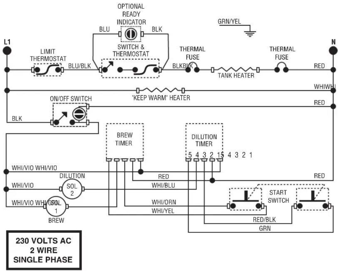
flowchart
graph TD
    A["230 VOLTS AC 2 WIRE SINGLE PHASE"] --> B["L1"]
    B --> C["LIMIT THERMOSTAT"]
    C --> D["BLU/BLK"]
    D --> E["OPTIONAL READY INDICATOR"]
    E --> F["SWITCH & THERMOSTAT"]
    F --> G["BLK"]
    G --> H["TANK HEATER"]
    H --> I["RED"]
    I --> J["WHI/WH"]
    B --> K["ON/OFF SWITCH"]
    K --> L["BLK"]
    L --> M["ON/OFF SWITCH"]
    M --> N["'KEEP WARM' HEATER"]
    N --> O["RED"]
    O --> P["BREW TIMER"]
    P --> Q["DILUTION TIMER"]
    Q --> R["5 4 3 2 15 4 3 2 1"]
    R --> S["RED"]
    S --> T["WHI/VIO WHI/VIO"]
    T --> U["DILUTION SOL 2"]
    U --> V["WHI/VIO WHI/SOL 1"]
    V --> W["BREW"]
    W --> X["WHI/ORN WHI/YEL"]
    X --> Y["START SWITCH"]
    Y --> Z["RED/BLK GRN"]
SCHEMATIC WIRING DIAGRAM
TB3B W/HALF-BATCH
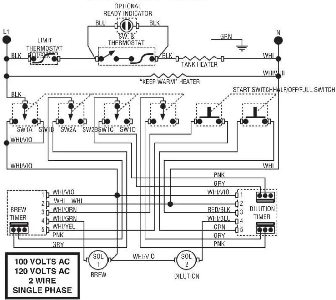
flowchart
graph TD
    A["100 VOLTS AC 120 VOLTS AC 2 WIRE SINGLE PHASE"] --> B["BREW TIMER"]
    B --> C["WHI/VIO"]
    B --> D["WHI ORN"]
    B --> E["WHI/GRN"]
    B --> F["WHI/YEL"]
    B --> G["PNK"]
    B --> H["GRY"]
    C --> I["SOL 1"]
    D --> J["SOL 2"]
    E --> K["DILUTION"]
    L["L1"] --> M["BLK"]
    M --> N["LIMIT THERMOSTAT BLU/BLK"]
    N --> O["SW. & THERMOSTAT"]
    O --> P["BLK"]
    P --> Q["TANK HEATER"]
    Q --> R["GRN"]
    R --> S["N"]
    T["WHI"] --> U["WHI/WI"]
    V["WHI"] --> W["WHI/HI"]
    X["WHI"] --> Y["WHI/VIO"]
    Z["WHI"] --> AA["WHI/VIO"]
    AB["WHI"] --> AC["WHI/VIO"]
    AD["WHI"] --> AE["WHI/VIO"]
    AF["WHI"] --> AG["WHI/VIO"]
    AH["WHI"] --> AI["WHI/VIO"]
    AJ["WHI"] --> AK["WHI/VIO"]
    AL["WHI"] --> AM["WHI/VIO"]
    AN["WHI"] --> AO["WHI/VIO"]
    AP["WHI"] --> AQ["WHI/VIO"]
    AR["WHI"] --> AS["WHI/VIO"]
    AT["WHI"] --> AU["WHI/VIO"]
    AV["WHI"] --> AW["WHI/VIO"]
    AX["WHI"] --> AY["WHI/VIO"]
    AZ["WHI"] --> BA["WHI/VIO"]
    BB["WHI"] --> BC["WHI/VIO"]
    BD["WHI"] --> BE["WHI/VIO"]
    BF["WHI"] --> BG["WHI/VIO"]
    BH["WHI"] --> BI["WHI/VIO"]
    BJ["WHI"] --> BK["WHI/VIO"]
    BL["WHI"] --> BM["WHI/VIO"]
    BN["L1"] --> BO["LIMIT THERMOSTAT BLU/BLK"]
    BO --> BR["SW. & THERMOSTAT BLK"]
    BR --> BS["TANK HEATER"]
    BS --> BT["GRN"]
    BT --> BU["N"]
    BV["WHI"] --> BW["WHI/HI"]
    BX["WHI"] --> BY["WHI/HI"]
    ZB["WHI"] --> CA["WHI/HI"]
    CBW["WHI"] --> CC["WHI/HI"]
    DDW["WHI"] --> EE["WHI/HI"]
    FFW["WHI"] --> GG["WHI/HI"]
    BHW["WHI"] --> BHW["WHI/HI"]
    BIW["WHI"] --> BIW["WHI/HI"]
    BJW["WHI"] --> BJW["WHI/HI"]
- OPERATING & SERVICE MANUAL
- BUNN-O-MATIC CORPORATION
- INTRODUCTION
- BUNN-O-MATIC COMMERCIAL PRODUCT WARRANTY
- USER NOTICES
- 00831.0000
- WARNING
- 37881.0000
- ! WARNING
- 03408.0000
- 03409.0000
- 00656.0000
- #06064.0000
- SEE
- INSTRUCTIONS
- 32540.0000
- BREWERS
- TIMER SETTING
- ELECTRICAL REQUIREMENTS
- Electrical Hook-Up
- PLUMBING REQUIREMENTS
- INITIAL SET-UP
- INITIAL SET-UP (cont.)
- ADJUSTING BREW VOLUMES
- AUTO SWEETENER SET-UP
- OPERATING CONTROLS
- ON/OFF Switch
- Start Switch
- UNSWEET/OFF/SWEET Selector Switch (Models with Sweetener Only)
- CLEANING
- CAUTION - CLEAN AND SANITIZE YOUR ICED TEA BREWER DAILY
- AUTO SWEETENER CLEANING
- TEA BREWING
- TROUBLESHOOTING
- WARNING -
- SERVICE
- COMPONENT ACCESS
- Contents
- SERVICE (cont.)
- BREW SOLENOID VALVE
- Location:
- Test Procedures:
- Removal and Replacement:
- CONTROL THERMOSTAT
- DIGITAL BREW TIMER
- Test Procedure:.
- Timer Setting:
- DIGITAL BREW TIMER (cont.)
- DILUTION SOLENOID VALVE
- Test Procedure:
- DILUTION TIMER
- LIMIT THERMOSTAT
- Removal and Replacement
- START SWITCH
- ON/OFF SWITCH
- Brewers W/Out Half Batch Option
- UNSWEET/OFF/SWEET SWITCH (Sweetner Option)
- SWEETNER SOLENOID VALVE
- TANK HEATER
Brand : Bunn
Model : TB3
Category : Teapot