
HA-450H - Loudspeaker TOA - Free user manual and instructions
Find the device manual for free HA-450H TOA in PDF.


| Product Type | Horn Array Speaker System |
| Brand | TOA |
| Model | HA-450H |
| Components Included | 4 Speaker Horns, 4 Speaker Drivers, 4 Driver Covers, 4 Driver Adapters, 4 Joining Plates, Hardware (Bolts, Nuts, Washers) |
| Rated Power | 200 W (4 x 50 W at 70 V line) |
| Impedance (Factory Setting) | Adjustable via transformer; default 50 W at 70 V line (per driver) |
| Frequency Response | 200 Hz – 16 kHz (typical for horn speakers) |
| Sensitivity | 105 dB SPL 1W/1m (typical) |
| Dispersion Angle | 60° horizontal x 40° vertical (typical for horn array) |
| Dimensions (approx.) | 600 mm x 600 mm x 500 mm (each horn approx. 300 mm) |
| Weight (approx.) | 30 kg (complete array) |
| Material | Horns: ABS plastic; Drivers: Metal; Covers: Metal/PVC |
| Color | Black (typical) |
| Weather Resistance | Drain hole for outdoor use; splash-proof design |
| Mounting | Multi-horn array via joining brackets; bolts included |
| Input Connection | Speaker cable via clamp terminal on driver cover |
| Application | Outdoor/indoor public address, paging systems, industrial signaling |
| Maintenance | Clean with dry cloth; check bolt tightness; verify cable connections |
| Safety | Use appropriate mounting hardware; ensure proper load distribution; avoid overloading amplifier |
| Spare Parts Availability | Contact TOA or authorized dealers for drivers and hardware |
Frequently Asked Questions - HA-450H TOA
User questions about HA-450H TOA
0 question about this device. Answer the ones you know or ask your own.
Ask a new question about this device
Download the instructions for your Loudspeaker in PDF format for free! Find your manual HA-450H - TOA and take your electronic device back in hand. On this page are published all the documents necessary for the use of your device. HA-450H by TOA.
USER MANUAL HA-450H TOA
This is a quick instruction guide for assembling the HA-450 series Horn Array Speaker System.
COMPONENTS
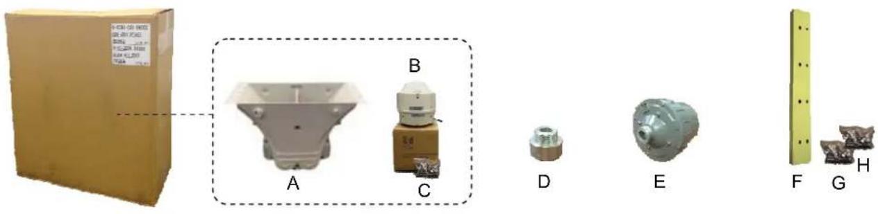
A: Speaker Horn (4 pcs)
B: Speaker Driver Cover (4 pcs)
C: Bolts, Nuts & Washers (4 bags)
D: Driver Adapter (4 pcs)
E: Speaker Driver (4 units)
F: Joining Plate (4 pcs)
G: M8 Bolts, Nuts & Washers x 7 sets (1 bag)
H: M10 Bolts, Nuts & Washers x 8 sets (1 bag)
INSTALLATION
- Place four Speaker Horns (A) next to each other on a flat surface with all brand logos located on the top side.
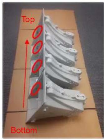
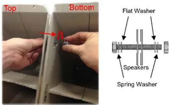
- Loosely fix all Speaker Horns (A) manually with the supplied M8x45mm bolts, nuts and washers (G).
- Loosely attach a first Joining Bracket (F) manually on the front side of the speaker with the supplied M6x30mm bolts, nuts and washers (C).
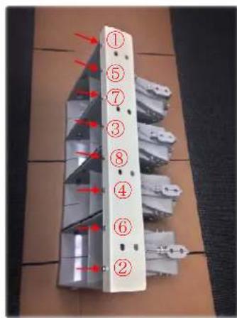
- Turn over the whole assembly and attach the second Joining Bracket (F) on the other side in the same manner.
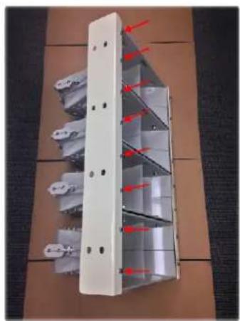
natural_image
Exterior view of a multi-tiered industrial storage unit with red arrows indicating flow or movement (no text or symbols visible)-
Attach the third Joining Bracket (F) manually on the rear side of the speaker with the supplied M10x25mm (H) and M10x35mm (C) bolts and washers.
-
Turn over the whole assembly and attach the fourth Joining Bracket (F) on the other side in the same manner.
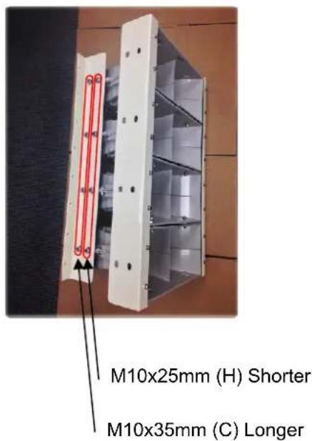
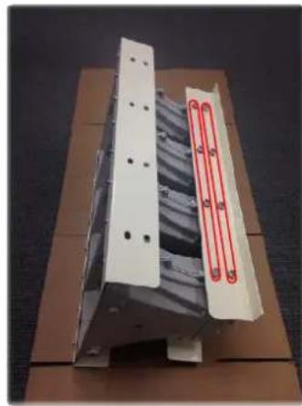
natural_image
Exterior view of a mechanical component with a red-labeled section (no visible text or symbols)-
Fix all bolts in 2, 3, 4, 5 and 6 tightly by using appropriate tools.
-
Place the assembly front side down as shown below.
-
Loosen the screw on the side of the mounting throat.
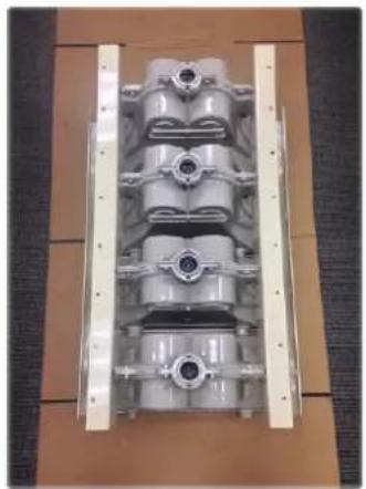
natural_image
Exterior view of a multi-tiered mechanical cylinder assembly mounted on a wooden base (no visible text or symbols)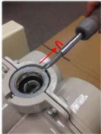
natural_image
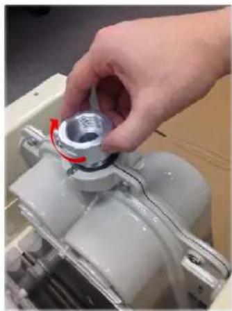
Close-up of a mechanical component with a hand holding a tool, showing a circular opening and red directional arrow (no text or symbols visible)- Screw in the Driver Adapter (D) tightly. 11. Tighten the side screw to fix the Adapter.
natural_image
Hand holding a metallic cylindrical component with red arrow indicating rotation (no text or symbols visible)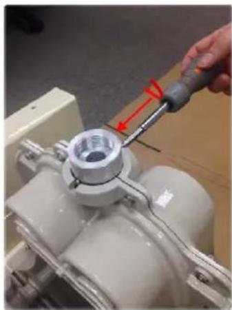
natural_image
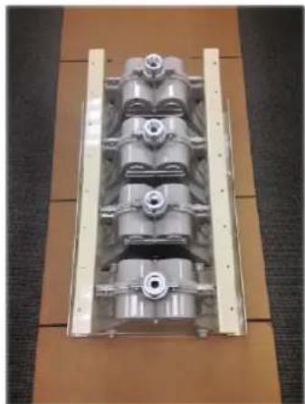
Close-up of a hand using a tool to adjust a mechanical component, with no visible text or symbols.- Attach other Driver Adapters (D) in the same manner.
natural_image
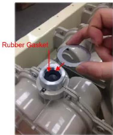
Exterior view of a multi-chamber engine cylinder mounted on a wooden frame (no text or symbols visible)- Put a Rubber Gasket inside of the Adapter and then place a spacer on the Adapter. (These two parts are supplied with the Driver Cover (B).)
- Put another spacer on the Driver Cover (D).
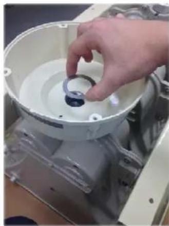
natural_image
Hand placing a small component into a white plastic housing (no visible text or symbols)- Put a Driver Cover (D) on the Adapter with the drain hole located on the bottom side.
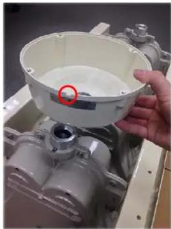
natural_image
Hand holding a white plastic housing component with a red circle highlighting a small feature, mounted on a mechanical assembly (no visible text or symbols)- Screw in the Speaker Driver (E.)
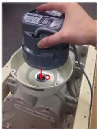
natural_image
Hand operating a battery on an electrical socket, with a red circular indicator showing the base (no visible text or symbols)- Put the speaker cable through the cable hole of the Driver Cover (D), and fix the clamp.
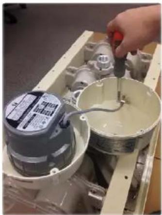
natural_image
Close-up of a hand using a pipette to adjust or inspect a mechanical component, with no visible text or symbols.-
Fix four screws on the Driver Cover.
-
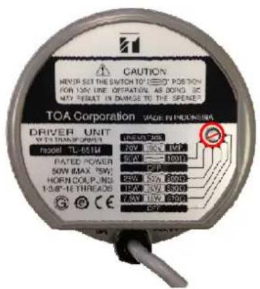
If you purchased "HA-450 H", adjust the transformer's impedance to meet your system design. (The factory setting is 50W@70V.)
- Attach other Speaker Drivers (E) and Covers (D) in the same manner.
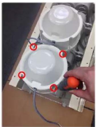
natural_image
Close-up of a hand holding an orange pushpin next to a white cylindrical device with red circular annotations (no text or symbols visible)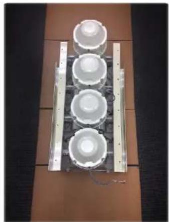
natural_image
Top-down view of a multi-tiered electronic device with four white circular components mounted on a metal frame (no visible text or symbols)Brand : TOA
Model : HA-450H
Category : Loudspeaker