
AquaLink Wireless Remote - Wireless remote Jandy - Free user manual and instructions
Find the device manual for free AquaLink Wireless Remote Jandy in PDF.


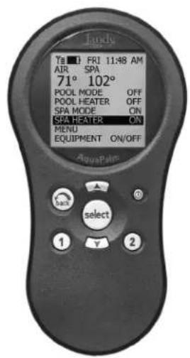
| Product Type | Wireless Handheld Remote for Pool/Spa Control Systems |
| Brand / Model | Jandy AquaLink Wireless Remote (AquaPalm) |
| Compatibility | AquaLink® RS OneTouch and All Button Systems (software rev. M or later) |
| Dimensions (H x W x D) | Approximately 6.5 x 2.5 x 1.2 inches |
| Weight (with batteries) | Approximately 0.4 lbs |
| Power Supply | 2 AA alkaline batteries |
| Battery Life | Extended with backlight off; auto shut-off (2, 5, or 10 min) |
| Wireless Frequency | 900 MHz (selectable RF channel) |
| Range | Through walls/obstructions; up to several hundred feet depending on environment |
| Display | LCD with backlight (optional) |
| Main Functions | Pool/Spa mode selection, equipment on/off, temperature setting, time setting, AquaPure chlorine generator control, hotkeys, boost, auto shut-off, backlight control |
| Control Buttons | Power, UP, DOWN, SELECT, BACK, Hotkeys 1 & 2 |
| Battery Status | Icon on display shows charge level; blinking icon indicates low battery |
| Signal Strength | Icon on display indicates signal quality; affected by distance and obstructions |
| Installation Requirements | Transceiver J-box mounted at least 6 ft above ground, 8 ft from blowers; antenna pointing skyward |
| Safety Certifications | FCC Class B, Part 15 compliant |
| Water Temperature Safety | Warnings: spa water ≤104°F; pregnant women limit to 100°F; alcohol/drug use dangerous |
| Electrical Safety | Requires GFCI for underwater lights; power center must be ≥5 ft from water |
| Maintenance | Replace AA batteries when low; clean with soft damp cloth; check/change 9V backup battery annually |
| Warranty | 1 year limited warranty (parts); extended with surge protection kit |
Frequently Asked Questions - AquaLink Wireless Remote Jandy
User questions about AquaLink Wireless Remote Jandy
0 question about this device. Answer the ones you know or ask your own.
Ask a new question about this device
Download the instructions for your Wireless remote in PDF format for free! Find your manual AquaLink Wireless Remote - Jandy and take your electronic device back in hand. On this page are published all the documents necessary for the use of your device. AquaLink Wireless Remote by Jandy.
USER MANUAL AquaLink Wireless Remote Jandy
Installation and Operation Manual
AquaPalm
Wireless Handheld Remote
(For use with AquaLink® RS
OneTouch and All Button Systems)
WARNING
FOR YOUR SAFETY - This product must be installed and serviced by a professional pool/spa service technician. The procedures in this manual must be followed exactly. Failure to follow warning notices and instructions may result in property damage, serious injury, or death.
ATTENTION
This device complies with part 15 of the FCC Rules. Operation is subject to the following two conditions: (1) This device may not cause harmful interference, and (2) this device must accept any interference received, including interference that may cause undesired operation.
NOTE: This equipment has been tested and found to comply with the limits for a Class B digital device, pursuant to part 15 of the FCC Rules. These limits are designed to provide reasonable protection against harmful interference in a residential installation. This equipment generates, uses and can radiate radio frequency energy and, if not installed and used in accordance with the instructions, may cause harmful interference to radio communications. However, there is no guarantee that interference will not occur in a particular installation. If this equipment does cause harmful interference to radio or television reception, which can be determined by turning the equipment off and on, the user is encouraged to try to correct the interference by one or more of the following measures:
- Reorient or relocate the receiving antenna.
- Increase the separation between the equipment and receiver.
- Connect the equipment to an electrical source on a circuit different from that to which the receiver is connected.
- Consult the dealer or an experienced radio/TV technician for help.
Modifications made to this equipment, which are not authorized by the manufacturer, may void the user's authority to operate this equipment.
Table of Contents
Section 1. Important Safety Instructions .... 4
Section 2. Product Description ...... 6
2.1 Basic Functions 6
2.2 AquaPalm Handheld Remote and Transceiver J-box Dimensions ..... 6
Section 3. Installation 6
3.1 AquaPalm Transceiver J-Box Cable Connection to Power Center PCB .. 6
3.2 AquaPalm Transceiver J-box Installation 7
3.3 AquaPalm Handheld Remote Installation 7
3.4 Changing the Frequency Channel .. 8
Section 4. AquaPalm Handheld Remote Operation 9
4.1 Basic Functions 9
4.2 Using the Buttons 9
4.3 Battery Status 10
4.4 Signal Strength 10
Section 5. AquaPalm Handheld Remote Menus 10
5.1 Pool Mode/Spa Mode 10
5.2 Equipment On/Off Menu 10
5.3 Filter Pump (Pool Mode) 11
5.4 Spa 11
5.5 Pool Heat 12
5.6 Spa Heat 12
5.7 Solar Heat 13
5.8 Auxiliary Equipment 13
5.9 Set Temperature Menu 14
5.10 Set Time Menu 14
5.11 AquaPure Menu 14
5.12 Auto Shut-off Menu 15
5.13 Backlight Menu 15
5.14 Assign Hotkeys Menu 15
5.15 Boost Menu 16
5.16 Battery Backup 16
5.17 AquaPalm Handheld Remote Menu Flow Chart 17
Section 6. Troubleshooting .... 18
6.1 AquaPalm Quick Troubleshooting Guide 18
EQUIPMENT INFORMATION RECORD
DATE OF INSTALLATION
INSTALLER INFORMATION
INITIAL PRESSURE GAUGE READING (WITH CLEAN FILTER)
PUMP MODEL
FILTER MODEL ____
AquaPalm MODEL SERIAL NUMBER
NOTES:
HORSEPOWER
SERIAL NUMBER ____
Section 1. Important Safety Instructions
READ AND FOLLOW ALL INSTRUCTIONS
LIRE LA NOTICE TECHNIQUE.
All electrical work must be performed by a licensed electrician and conform to all national, state, and local codes. When installing and using this electrical equipment, basic safety precautions should always be followed, including the following:

DANGER
To reduce the risk of injury, do not remove the suction fittings of your spa or hot tub. Never operate a spa or hot tub if the suction fittings are broken or missing. Never replace a suction fitting with one rated less than the flow rate marked on the equipment assembly.

WARNING
Prolonged immersion in hot water may induce hyperthermia. Hyperthermia occurs when the internal temperature of the body reaches a level several degrees above the normal body temperature of 98.6° F. The symptoms of hyperthermia include dizziness, fainting, drowsiness, lethargy, and an increase in the internal temperature of the body. The effects of hyperthermia include: 1) unawareness of impending danger; 2) failure to perceive heat; 3) failure to recognize the need to exit spa; 4) physical inability to exit spa; 5) fetal damage in pregnant women; 6) unconsciousness resulting in a danger of drowning.

WARNING
To Reduce the Risk of Injury -
a) The water in a spa should never exceed 104^ F ( 40^ C). Water temperatures between 100^ F ( 38^ C) and 104^ F ( 40^ C) are considered safe for a healthy adult. Lower water temperatures are recommended for young children and when spa use exceeds 10 minutes.
b) Since excessive water temperatures have a high potential for causing fetal damage during the early months of pregnancy, pregnant or possibly pregnant women should limit spa water temperatures to 100^ F ( 38^ C).
c) Before entering a spa or hot tub, the user should measure the water temperature with an accurate thermometer since the tolerance of water temperature-regulating devices varies.
d) The use of alcohol, drugs, or medication before or during spa or hot tub use may lead to unconsciousness with the possibility of drowning.
e) Obese persons and persons with a history of heart disease, low or high blood pressure, circulatory system problems, or diabetes should consult a physician before using a spa.
f) Persons using medication should consult a physician before using a spa or hot tub since some medication may induce drowsines while other medication may affect heart rate, blood pressure, and circulation.

WARNING
Risk of electric shock - Install the power center at least five (5) feet (152.4cm) from the inside wall of the pool and/or hot tub using non-metallic plumbing. Canadian installations must be at least three (3) meters from the water.
Children should not use spas or hot tubs without adult supervision.
Do not use spas or hot tubs unless all suction guards are installed to prevent body and hair entrapment.
People using medications and/or having an adverse medical history should consult a physician before using a spa or hot tub.

AVERTISSEMENT
People with infectious diseases should not use a spa or hot tub.
To avoid injury, exercise care when entering or exiting the spa or hot tub.
Do not use drugs or alcohol before or during the use of a spa or hot tub to avoid unconsciousness and possible drowning.
Pregnant or possibly pregnant women should consult a physician before using a spa or hot tub.
Water temperature in excess of 100^ F/38°C may be injurious to your health.
Before entering a spa or hot tub measure the water temperature with an accurate thermometer.
Do not use a spa or hot tub immediately following strenuous exercise.
Prolonged immersion in a spa or hot tub may be injurious to your health.
Do not permit any electric appliance (such as a light, telephone, radio, or television) within 5 feet (1.5 m) of a spa or hot tub.
The use of alcohol, drugs or medication can greatly increase the risk of fatal hyperthermia in hot tubs and spas.
Water temperature in excess of 100^ F/38°C may be hazardous to your health.
AVERTISSEMENT
To avoid injury ensure that you use this control system to control only packaged pool/spa heaters which have built-in operating and high limit controls to limit water temperature for pool/spa applications. This device should not be relied upon as a safety limit control.
CAUTION
A terminal bar marked "GROUND" is provided within the power center. To reduce the risk of electrical shock, connect this terminal bar to the grounding terminal of your electric service or supply panel with a continuous copper conductor having green insulation and one that is equivalent in size to the circuit conductors supplying this equipment, but no smaller than no. 12 AWG (3.3mm). In addition, a second wire connector should be bonded with a no. 8 AWG (4.115mm) copper wire to any metal ladders, water pipes, or other metal within five (5) feet (1.52m) of the tub.
CAUTION
A ground-fault circuit-interrupter must be provided if this device is used to control underwater lighting fixtures. The conductors on the load side of the ground-fault circuit-interrupter shall not occupy conduit, boxes, or enclosures containing other conductors unless the additional conductors are also protected by a ground-fault circuit-interrupter. Refer to local codes for complete details.

Attention installer: Install to provide drainage of compartment for electrical components.
Section 2. Product Description
NOTE For use with an AquaLink® RS System ONLY, software revision "M" or later.
This document gives instructions for installing and operating the Jandy AquaLink® RS AquaPalm. The instructions must be followed exactly. Read through the instructions completely before operating the equipment.
2.1 Basic Functions
The AquaPalm Handheld Remote can be used in addition to an already existing AquaLink RS control system. The AquaPalm can turn your pool/spa equipment on and off in one of the following ways:
- Activate the equipment manually through the EQUIPMENT ON/OFF menu.
- Use the AquaPalm Handheld Remote buttons 1 or 2 (Hotkeys). See Section 5.13 for a detailed explanation of how to program Hotkeys 1 and 2.
2.2 AquaPalm Handheld Remote and Transceiver J-box Dimensions
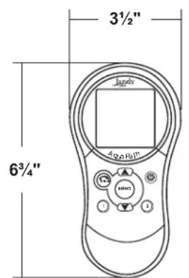
Front View
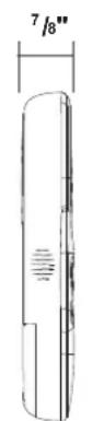
Side View
Figure 1. AquaPalm Handheld Remote Dimensions
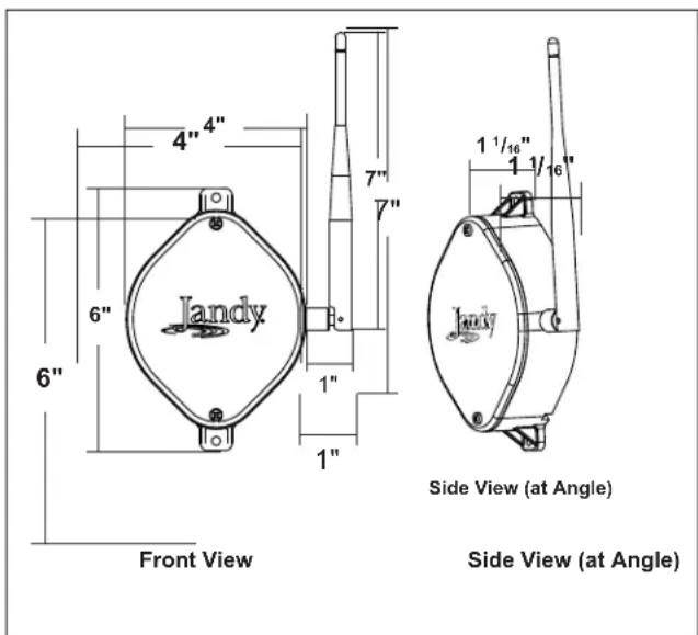
Figure 2. J-Box Transceiver Dimensions
Section 3. Installation

WARNING
Potentially high voltages in the AquaLink RS Power Center can create dangerous electrical hazards, possibly causing death, serious injury or property damage. Turn off power at the main circuit feeding the AquaLink RS Power Center to disconnect the Power Center from the system.
3.1 AquaPalm Transceiver J-Box Cable Connection to Power Center PCB
Make provisions for the cable to be run between the AquaPalm Transceiver J-box and the AquaLink RS Power Center. Never run high voltage and low voltage in the same conduit.
- Turn off all power to the Power Center.
- Pull cable through the knockout with the Heyco fitting and into the low voltage compartment (see Figure 3).
- Strip back the insulation jacket of the cable approximately 6".
- Strip each wire 14 " and connect to the red, 4-pin connector on the Power Center PCB. A multiplex kit may be required if there are more than two cables running to a red, 4-pin connector (see Figure 3) on the PCB.
NOTE For detailed tranceiver installation, see Section 3.2.
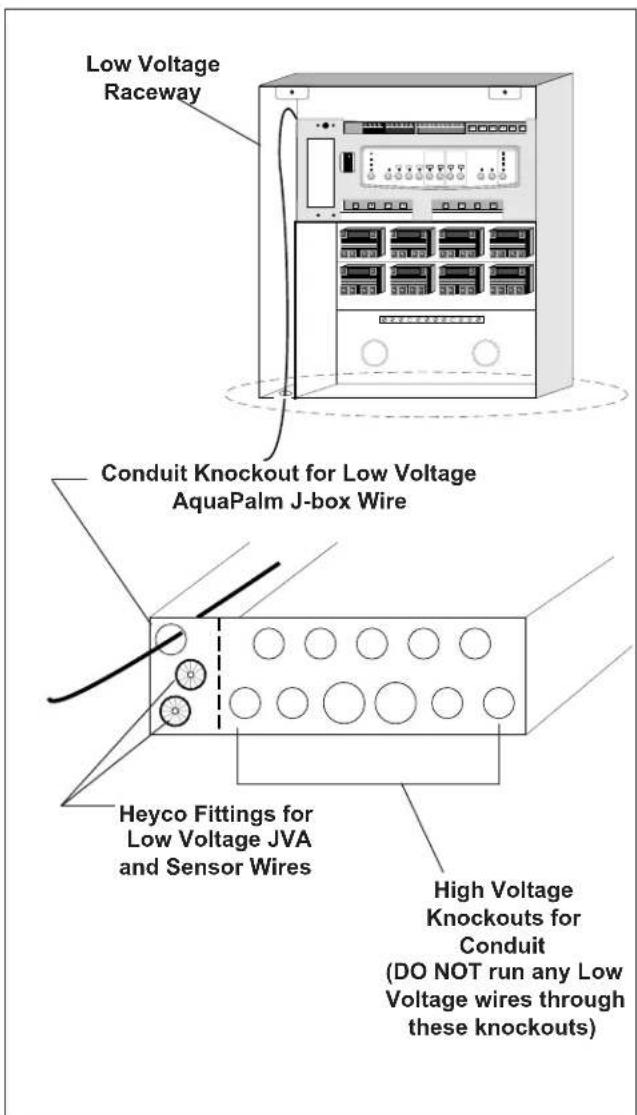
Figure 3. AquaPalm J-Box Cable Connection to Power Center PCB
3.2 AquaPalm Transceiver J-box Installation
Installation Considerations. The transceivers will transmit through walls and around corners. Steel framing, aluminum siding, wrought iron, cyclone fences, leaded glass, and other 900 MHz frequency items may inhibit/prevent communication between the AquaLink RS AquaPalm Handheld Remote and the Power Center. The transceivers do not require line of sight to communicate. To optimize communication, install transceivers in a location that minimizes interference.
- Turn off all power to the Power Center.
- Mount the Outdoor Transceiver J-box at least 6' above the ground and at least 8' from any air blowers that may be in the vicinity (see Figure 4).
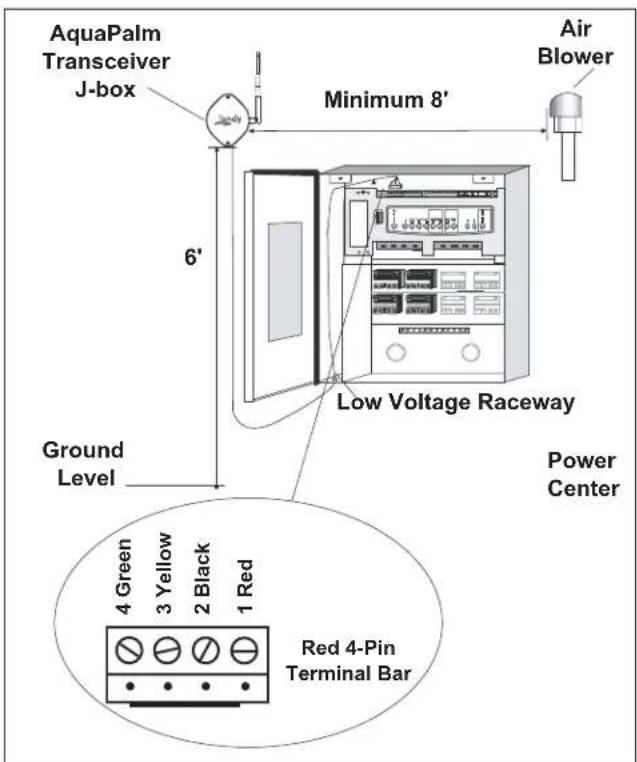
Figure 4. Outdoor Transceiver J-box Installation
- The Transceiver J-box antenna must point towards the sky.
NOTE To improve performance of the transceiver, mount the J-box more than 6' above the ground.
- Open the door to the Power Center and remove the dead panel.
- Feed the four conductor wire into the Power Center through the low voltage raceway.
- Cut off the excess wire. Strip the jacket back 6" and strip the individual wires approximately 14 ". Connect the four conductor wire to the red terminal bar on the Power Center PCB.
- Install the dead panel to the Power Center and restore all power.
3.3 AquaPalm Handheld Remote Installation
- Remove the Handheld Remote from the packaging.
- On the back of the Handheld Remote, loosen and remove the two (2) screws that secure the cover for the battery chamber (see Figure 5).
- Install two (2) AA batteries. Ensure that the polarity is correct.
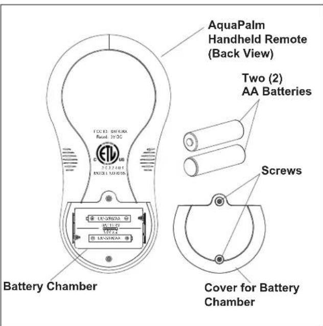
Figure 5. Battery Installation on Handheld Remote
- Re-install the cover for the battery chamber and secure with the two (2) screws removed in Step 2.
3.4 Changing the Frequency Channel
If your AquaLink RS AquaPalm system is turning items on or off at undesignated times, another AquaLink RS AquaPalm system may be in close proximity using the same or similar frequency channel. To prevent unwanted operation the channel for your AquaLink RS AquaPalm system can be changed. The AquaPalm Handheld Remote and the AquaPalm Transceiver J-box must be set to the same RF channel.
-
At the Transceiver J-box, remove the cover to expose the PCB (see Figure 6).
-
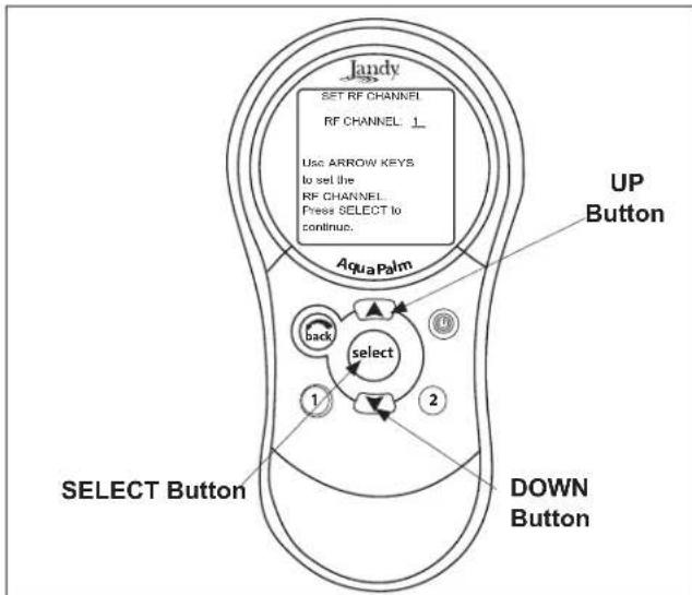
On the AquaPalm Handheld Remote, press and hold both the UP and DOWN arrows simultaneously for three (3) seconds. After 3 seconds, the CHANNEL SETUP screen appears (see Figure 7). Select a channel.
-
Use the UP and DOWN buttons to highlight the desired RF channel. Then press SELECT.
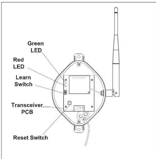
Figure 6. AquaPalm Transceiver J-Box - Internal View
flowchart
graph TD
    A["UP Button"] --> B["Select Button"]
    B --> C["DOWN Button"]
    C --> D["AquaPalm"]
    D --> E["Back"]
    E --> F["select"]
    F --> G["1"]
    F --> H["2"]
    G --> I["Use ARROW KEYS to set the RF CHANNEL. Press SELECT to continue."]
    H --> J["Start of loop"]
    I --> K["End of loop"]
Figure 7. AquaPalm Handheld Remote Channel Setup and Buttons
-
When the RF channel is selected, the following message appears on the AquaPalm display screen: Set slide switch on J-Box PCB to the LEARN MODE.
-
At the PCB in the Transceiver J-box, slide the Learn Switch to LEARN (ON). See Figure 8.
-
On the AquaPalm Handheld Remote display screen, a prompt will appear with instructions to slide the J-box Learn Switch out of LEARN (OFF) and to press the J-box Reset Switch (see Figure 8).
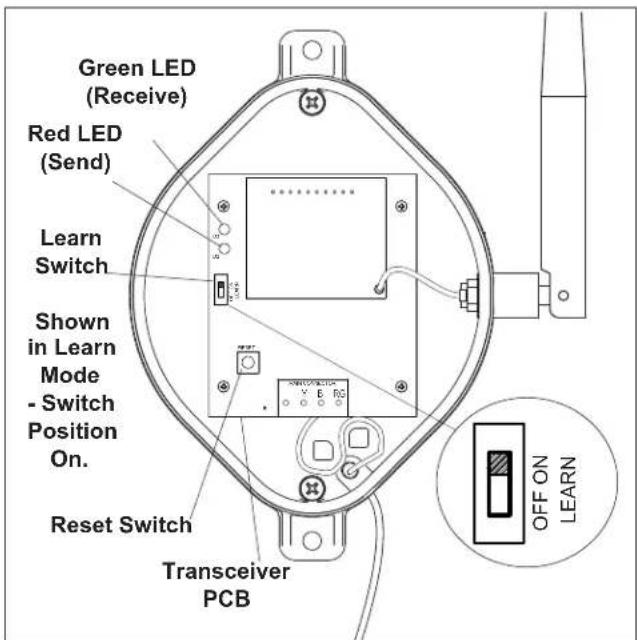
Figure 8. Tranceiver J-box PCB Learn Switch
- At the PCB in the Transceiver J-box, slide the Learn Switch out of LEARN (ON) and press the Reset Switch. The Red and Green LEDs on the J-box will blink simultaneously (see Figure 8).
Section 4. AquaPalm Handheld Remote Operation
4.1 Basic Functions
Use the AquaPalm Handheld Remote to turn your pool/spa equipment on and off in one of the following ways:
-
Activate the main equipment on the front screen by highlighting the selection, then press SELECT.
-
Activate the equipment manually through the EQUIPMENT ON/OFF menu.
-
Use the Hotkey buttons 1 or 2 (see Figure 9). See Section 5.13 for a detailed explanation of how to program Hotkeys 1 and 2.
NOTE The default setting for Hotkeys 1 and 2 are AUX1 and AUX2 respectively. However, these buttons can be assigned to any piece of equipment or OneTouch Mood setting.
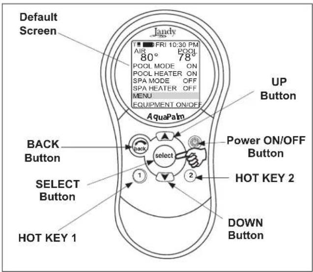
Figure 9. AquaPalm Handheld Remote Buttons
4.2 Using the Buttons
Use the buttons as explained in Figure 10.
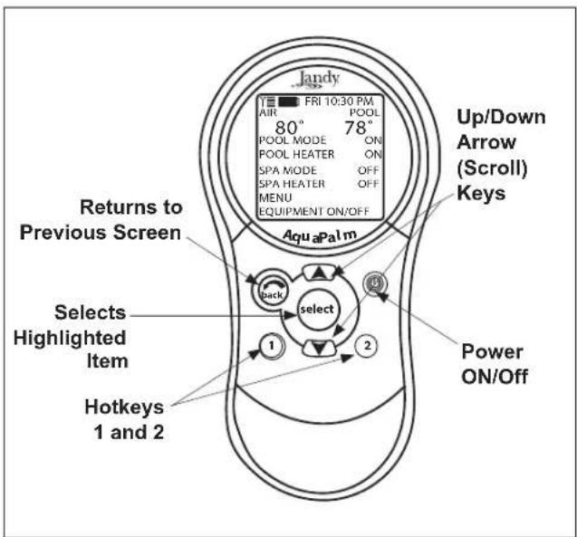
Figure 10. AquaPalm Handheld Remote Buttons Function
4.3 Battery Status
The Battery icon is located on the left corner of the display screen, indicates the status of the battery. The AquaPalm Handheld Remote uses two (2) AA batteries. The batteries are located behind the cover on the back side of the Handheld Remote. If the batteries have full or sufficient charge, the icon will appear on the display screen as [1] the batteries need to be replaced, the icon will consistently blink and appear as [2]
4.4 Signal Strength
The Signal Strength icon is located on the left corner of the display screen, indicates the signal strength available from the Transceiver J-box to the AquaPalm Handheld Remote. Signal strength is affected (lowered) as the AquaPalm Handheld Remote is moved farther away from the Transceiver J-Box. Also, obstructions, such as walls or other wireless products, can lower the signal strength if located between the AquaPalm Handheld Remote and the Transceiver J-Box. The Transceiver J-box must also be installed at least 6 feet off the ground, 8 feet away from equipment, and the antenna pointing towards the sky.
Section 5. AquaPalm Handheld Remote Menus
5.1 Pool Mode/Spa Mode
When POOL MODE is selected, valve actuators turn the valves to pool return (pool/spa combination systems) and the filter pump turns on. If POOL HEAT is enabled, the heater will fire and heat the water to the set temperature.
When SPA MODE is selected, the valve actuators rotate to allow flow to the spa (pool/spa combination systems) and the filter pump is turned on. If SPA HEAT is enabled, the heater will fire and heat the water to the set temperature.
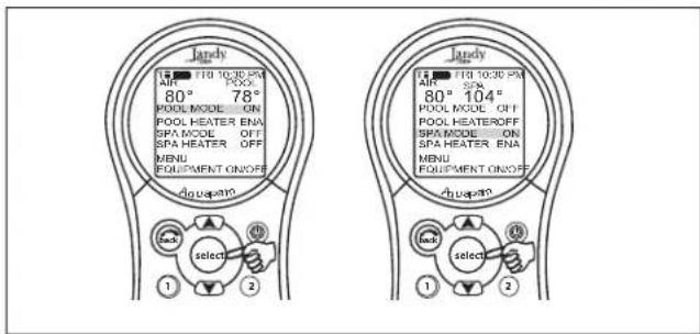
Figure 11. Pool Mode and Spa Mode Menus
5.2 Equipment On/Off Menu
EQUIPMENT ON/OFF > ALL OFF
Use this menu to turn a piece of equipment on or off. The ALL OFF mode will turn off equipment that has been turned on by any means (manual or pre-programmed). This includes any of the heater enables that were on (unless in use by the Maintain function).
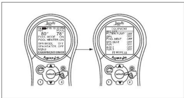
Figure 12. Equipment On/Off Menu - All Off
To use Equipment On/Off
- Highlight EQUIPMENT ON/OFF and press SELECT. To highlight an item, use the UP/DOWN arrow keys. Use the SELECT button to turn the equipment on or off. Return to the main menu by using the BACK button, or use the UP/DOWN arrow keys to highlight another device.
- Highlight ALL OFF and press SELECT. After using ALL OFF, return to the main menu by using the BACK button.
5.3 Filter Pump (Pool Mode)
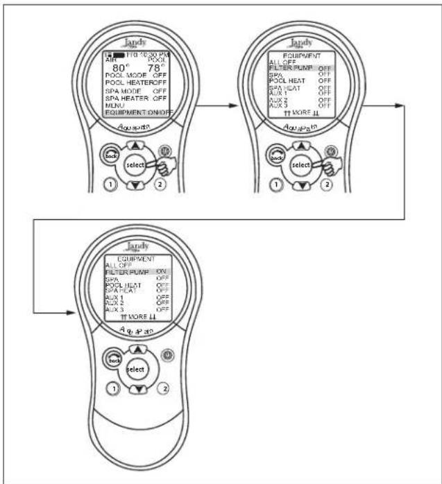
EQUIPMENT ON/OFF > FILTER PUMP
The FILTER PUMP selection turns the main filtration pump on or off for circulation to the pool. The filter pump also activates if the spa is turned on, if the pool cleaner is turned on, or if the spa spill-over effect is activated. The main filtration pump circulates the pool or spa water through the filter and heater. The pump must be on if you want to display the pool temperature, or if you want to heat the pool.
flowchart
graph TD
    A["Top Panel: Jardy"] --> B["Top Panel: Equipment"]
    B --> C["Bottom Panel: Aq. 4.4.0"]
    A -->|select| D["Top Panel: Equipment"]
    B -->|select| E["Top Panel: Equipment"]
    A -->|1| F["Top Panel: Equipment"]
    B -->|2| G["Top Panel: Equipment"]
    A -->|1| H["Top Panel: Equipment"]
    B -->|2| I["Top Panel: Equipment"]
Figure 13. Equipment On/Off Menu - Filter Pump
To use Filter Pump
Highlight FILTER PUMP and press SELECT. Use the SELECT button to turn the equipment on or off.
5.4 Spa
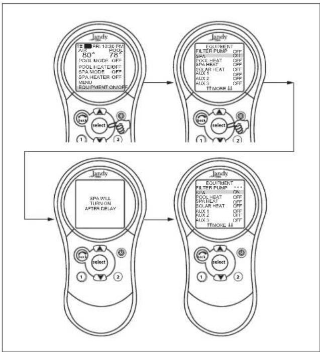
EQUIPMENT ON/OFF > SPA
The SPA selection switches water circulation from the pool to spa (pool/spa combination models only). Turning on the spa also activates the filter pump (after a delay for valve rotation) and deactivates the pool cleaner if it is on. The SPA mode must be on to display the spa temperature and/or to heat the spa. Activation takes place after a thirty second delay (while valves are turning).
flowchart
graph TD
    A["Top Setup"] --> B["Top Equipment"]
    B --> C["Bottom Setup"]
    A --> D["Top Equipment"]
    D --> E["Bottom Equipment"]
    A --> F["Top Equipment"]
    F --> G["Bottom Equipment"]
    A --> H["Top Equipment"]
    H --> I["Bottom Equipment"]
    A --> J["Top Equipment"]
    J --> K["Bottom Equipment"]
    A --> L["Top Equipment"]
    L --> M["Bottom Equipment"]
    A --> N["Top Equipment"]
    N --> O["Bottom Equipment"]
    A --> P["Top Equipment"]
    P --> Q["Bottom Equipment"]
    A --> R["Top Equipment"]
    R --> S["Bottom Equipment"]
    A --> T["Top Equipment"]
    T --> U["Bottom Equipment"]
    A --> V["Top Equipment"]
    V --> W["Bottom Equipment"]
    A --> X["Top Equipment"]
    X --> Y["Bottom Equipment"]
    A --> Z["Top Equipment"]
    Z --> AA["Bottom Equipment"]
    A --> AB["Top Equipment"]
    AB --> AC["Bottom Equipment"]
    A --> AD["Top Equipment"]
    AD --> AE["Bottom Equipment"]
    A --> AF["Top Equipment"]
    AF --> AG["Bottom Equipment"]
    A --> AH["Top Equipment"]
    AH --> AI["Bottom Equipment"]
    A --> AJ["Top Equipment"]
    AJ --> AK["Bottom Equipment"]
    A --> AL["Top Equipment"]
    AL --> AM["Bottom Equipment"]
    A --> AN["Top Equipment"]
    AN --> AO["Bottom Equipment"]
    A --> AP["Top Equipment"]
    AP --> AQ["Bottom Equipment"]
    A --> AR["Top Equipment"]
    AR --> AS["Bottom Equipment"]
Figure 14. Equipment On/Off Menu - Spa
To use Spa
Highlight SPA and press SELECT. Use the SELECT button to turn the spa on or off.
NOTE The filter pump turns off during the valve rotation.
5.5 Pool Heat
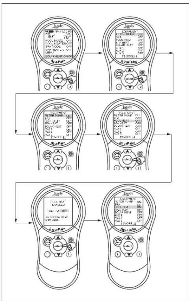
EQUIPMENT ON/OFF > FILTER PUMP > POOL HEAT > (Set to Desired Temperature)
The POOL HEAT selection enables the heater for the pool. It uses the setting from SET TEMP menu, or you can increase/decrease when enabling.
flowchart
graph TD
    A["Top Panel: 'Jandy' with 100% power, 80°/78°, 300% power, 200% power"] --> B["Top Panel: 'Jandy' with 100% power, 80°/78°, 300% power, 200% power"]
    B --> C["Top Panel: 'Jandy' with 100% power, 80°/78°, 300% power, 200% power"]
    C --> D["Top Panel: 'Jandy' with 100% power, 80°/78°, 300% power, 200% power"]
    D --> E["Top Panel: 'Jandy' with 100% power, 80°/78°, 300% power, 200% power"]
    E --> F["Top Panel: 'Jandy' with 100% power, 80°/78°, 300% power, 200% power"]
    F --> G["Top Panel: 'Jandy' with 100% power, 80°/78°, 300% power, 200% power"]
    G --> H["Top Panel: 'Jandy' with 100% power, 80°/78°, 300% power, 200% power"]
    H --> I["Top Panel: 'Jandy' with 100% power, 80°/78°, 300% power, 200% power"]
    I --> J["Top Panel: 'Jandy' with 100% power, 80°/78°, 300% power, 200% power"]
    J --> K["Top Panel: 'Jandy' with 100% power, 80°/78°, 300% power, 200% power"]
    K --> L["Top Panel: 'Jandy' with 100% power, 80°/78°, 300% power, 200% power"]
    L --> M["Top Panel: 'Jandy' with 100% power, 80°/78°, 300% power, 200% power"]
    M --> N["Top Panel: 'Jandy' with 100% power, 80°/78°, 300% power, 200% power"]
    N --> O["Top Panel: 'Jandy' with 100% power, 80°/78°, 300% power, 200% power"]
    O --> P["Top Panel: 'Jandy' with 100% power, 80°/78°, 300% power, 200% power"]
    P --> Q["Top Panel: 'Jandy' with 100% power, 80°/78°, 300% power, 200% power"]
    D --> R["Top Panel: 'Jandy' with select units (select) for two main devices"]
    R --> S["Top Panel: 'Jandy' with select units (select) for two main devices"]
    S --> T["Top Panel: 'Jandy' with select units (select) for two main devices"]
    T --> U["Top Panel: 'Jandy' with select units (select) for two main devices"]
Figure 15. Equipment On/Off Menu - Pool Heat
To use Pool Heat
Highlight FILTER PUMP and press SELECT. Highlight POOL HEAT and press SELECT. Use the UP/DOWN arrow keys to set the desired temperature and press SELECT.
5.6 Spa Heat
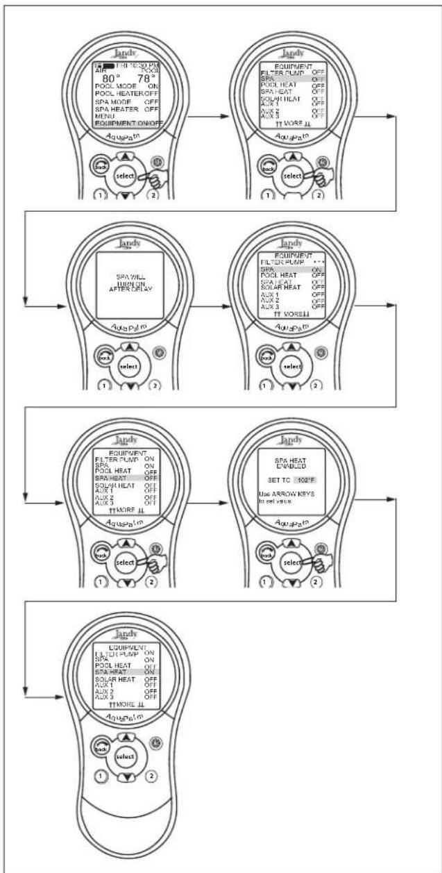
EQUIPMENT ON/OFF > SPA > SPA HEAT > (Set to Desired Temperature)
The SPA HEAT enables the heater for the spa. The desired temperature can be set from the SET TEMP menu, or you can increase/decrease the temperature when enabling the heater.
flowchart
graph TD
    A["180°/30PM AIR 80° 78 POOL MODE ON SPA MODE OFF SPA HEATER OFF MENU EQUIPMENT ON/OFF AcupPatn"] --> B[" select (1)"]
    B --> C[" select (2)"]
    C --> D["1"]
    D --> E["2"]
    E --> F["1"]
    F --> G["2"]
    G --> H["1"]
    H --> I["2"]
    I --> J["1"]
    J --> K["2"]
    K --> L["1"]
    L --> M["2"]
    M --> N["1"]
    N --> O["2"]
    O --> P["1"]
    P --> Q["2"]
    Q --> R["1"]
    R --> S["2"]
    S --> T["1"]
    T --> U["2"]
    U --> V["1"]
    V --> W["2"]
    W --> X["1"]
    X --> Y["2"]
    Y --> Z["1"]
    Z --> AA["2"]
    AA --> AB["1"]
    AB --> AC["2"]
    AC --> AD["1"]
    AD --> AE["2"]
    AE --> AF["1"]
    AF --> AG["2"]
    AG --> AH["1"]
    AH --> AI["2"]
    AI --> AJ["1"]
    AJ --> AK["2"]
    AK --> AL["1"]
    AL --> AM["2"]
    AM --> AN["1"]
    AN --> AO["2"]
    AO --> AP["1"]
    AP --> AQ["2"]
    AQ --> AR["1"]
    AR --> AS["2"]
    AS --> AT["1"]
    AT --> AU["2"]
    AU --> AV["1"]
    AV --> AW["2"]
    AW --> AX["1"]
    AX --> AY["2"]
    AY --> AZ["1"]
    AZ --> BA["2"]
    BA --> BB["1"]
    BB --> BC["2"]
    BC --> BD["1"]
    BD --> BE["2"]
    BE --> BF["1"]
    BF --> BG["2"]
    BG --> BH["1"]
    BH --> BI["2"]
    BI --> BJ["1"]
    BJ --> BK["2"]
    BK --> BL["1"]
    BL --> BM["2"]
    BM --> BN["1"]
    BN --> BO["2"]
    BO --> BP["1"]
    BP --> BQ["2"]
    BQ --> BR["1"]
    BR --> BS["2"]
    BS --> BT["1"]
    BT --> BU["2"]
    BU --> BV["1"]
    BV --> BW["2"]
    BW --> BX["1"]
    BX --> BY["2"]
    BY --> BZ["1"]
    BZ --> CA["2"]
    CA --> CB["1"]
    CB --> CC["2"]
    CC --> CD["1"]
    CD --> CE["2"]
    CE --> CF["1"]
    CF --> CG["2"]
    CG --> CH["1"]
    CH --> CI["2"]
    CI --> CJ["1"]
    CJ --> CK["2"]
    CK --> CL["1"]
    CL --> CM["2"]
    CM --> CN["1"]
    CN --> CO["2"]
    CO --> CP["1"]
    CP --> CQ["2"]
    CQ --> CR["1"]
    CR --> CS["2"]
    CS --> CT["1"]
    CT --> CU["2"]
    CU --> CV["1"]
    CV --> CW["2"]
    CW --> CX["1"]
    CX --> CY["2"]
    CY --> CZ["1"]
    CZ --> DA["2"]
    DA --> DB["1"]
    DB --> DC["2"]
    DC --> DD["1"]
    DD --> DE["2"]
    DE --> DF["1"]
    DF --> DG["2"]
Figure 16. Equipment On/Off Menu - Spa Heat
To use Spa Heat
Highlight SPA and press SELECT. The spa will come on after a short delay. Highlight SPA HEAT and press SELECT. Use the UP/DOWN arrow keys to set the desired temperature and press SELECT.
5.7 Solar Heat
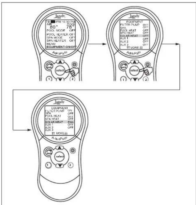
EQUIPMENT ON/OFF > SOLAR HEAT
The SOLAR HEAT selection controls solar heating. A solar heating system and optional solar sensor are required for SOLAR HEAT selection to operate and must be part of the normal circulation system.
flowchart
graph TD
    A["Panel 1: Lamp Control"] --> B["Panel 2: Equipment"]
    B --> C["Panel 3: Control Panel"]

    subgraph Panel_1
        A1["FR1 10:30 PM AIR 80° 78 POOL MODE OFF SPA MODE OFF SPA HEATER OFF MLNU EQUIPMENT ON/OFF"]
        B1["EQUIPMENT FILTER PUMP OFF SPA HEAT OFF SOLAR HEAT OFF AUX 1 OFF AUX 2 OFF TT MORE ↑"]
        C1["select"]
        D1["select"]
    end

    subgraph Panel_2
        B2["App Poh"]
        C2["App Poh"]
        D2["App Poh"]
    end

    subgraph Panel_3
        E1["UPP"]
        F1["UPP"]
        G1["UPP"]
        H1["UPP"]
        I1["UPP"]
        J1["UPP"]
        K1["UPP"]
        L1["UPP"]
        M1["UPP"]
        N1["UPP"]
        O1["UPP"]
        P1["UPP"]
        Q1["UPP"]
        R1["UPP"]
        S1["UPP"]
        T1["UPP"]
        U1["UPP"]
        V1["UPP"]
        W1["UPP"]
        X1["UPP"]
        Y1["UPP"]
        Z1["UPP"]
        AA1["UPP"]
        AB1["UPP"]
        AC1["UPP"]
        AD1["UPP"]
        AE1["UPP"]
        AF1["UPP"]
        AG1["UPP"]
        AH1["UPP"]
        AI1["UPP"]
        AJ1["UPP"]
        AK1["UPP"]
        AL1["UPP"]
        AM1["UPP"]
        AN1["UPP"]
        AO1["UPP"]
        AP1["UPP"]
        AQ1["UPP"]
        AR1["UPP"]
    end
Figure 17. Equipment On/Off Menu - Solar Heat
To use Solar Heat
Highlight SOLAR HEAT and press SELECT. Use the SELECT button to turn SOLAR HEAT on or off.
HEAT PUMP: If the solar circuit is controlling a heat pump, the label HEAT PUMP will appear on the screen in place of SOLAR HEAT.
NOTE The label HEAT PUMP may take up to 24 hours to appear on the screen after initial heat pump installation.
If a solar sensor is not installed, EXTRA AUX replaces SOLAR HEAT and may be used to control an auxiliary (see "Auxiliary Equipment" to turn on or off EXTRA AUX).
For solar heating to take place, the SOLAR HEAT (in EQUIPMENT ON/OFF) must be enabled, also the filter pump must be on. Solar temperature must be at least 5°F above the water temperature and the water must be cooler than the thermostat setting.
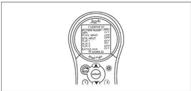
Figure 18. Equipment On/Off Menu - Solar Sensor not Installed
NOTE If a Solar Sensor is not installed, EXTRA AUX will appear as a menu item.
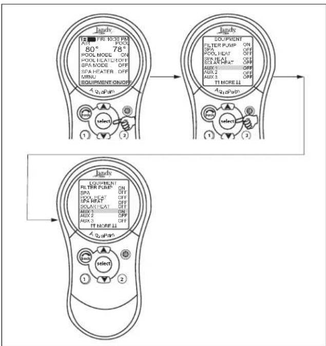
5.8 Auxiliary Equipment
EQUIPMENT ON/OFF > AUX (Select desired Aux)
The AUX modes control each of the auxiliary devices plus an extra AUX.
NOTE Auxiliary devices are items or equipment such as pool and spa lights, waterfalls, or air blowers.
flowchart
graph TD
    A["Top Panel: Jandy 10:30 PM"] --> B["Top Panel: Equipment ON/OFF"]
    B --> C["Bottom Panel: Equipment ON/OFF"]
    A --> D["Top Panel: Jandy 78° OFF"]
    D --> E["Top Panel: Jandy 78° OFF"]
    A --> F["Top Panel: Jandy 78° OFF"]
    F --> G["Top Panel: Jandy 78° OFF"]
    A --> H["Top Panel: Jandy 78° OFF"]
    H --> I["Top Panel: Jandy 78° OFF"]
    A --> J["Top Panel: Jandy 78° OFF"]
    J --> K["Top Panel: Jandy 78° OFF"]
    A --> L["Top Panel: Jandy 78° OFF"]
    L --> M["Top Panel: Jandy 78° OFF"]
    A --> N["Top Panel: Jandy 78° OFF"]
    N --> O["Top Panel: Jandy 78° OFF"]
    A --> P["Top Panel: Jandy 78° OFF"]
    P --> Q["Top Panel: Jandy 78° OFF"]
    A --> R["Top Panel: Jandy 78° OFF"]
    R --> S["Top Panel: Jandy 78° OFF"]
    A --> T["Top Panel: Jandy 78° OFF"]
    T --> U["Top Panel: Jandy 78° OFF"]
    A --> V["Top Panel: Jandy 78° OFF"]
    V --> W["Top Panel: Jandy 78° OFF"]
    A --> X["Top Panel: Jandy 78° OFF"]
    X --> Y["Top Panel: Jandy 78° OFF"]
    A --> Z["Top Panel: Jandy 78° OFF"]
    Z --> AA["Top Panel: Jandy 78° OFF"]
Figure 19. Equipment On/Off Menu - Auxiliary Equipment
To turn an Auxiliary On or Off
Highlight EQUIPMENT ON/OFF and press SELECT. Highlight an AUX and press SELECT. Use the SELECT button to turn the equipment on or off.
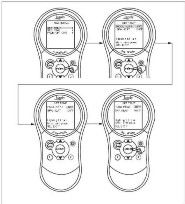
5.9 Set Temperature Menu
MENU > SET TEMP > POOL or SPA > SET TEMP VALUE
The SET TEMP menu allows you to preset the pool and spa thermostats.
NOTE For pool/spa combination systems, the default pool temperature is 80^ F and the default spa temperature is 102^ F. For pool only/spa only systems, the default TEMP1 temperature is 80^ F and the default TEMP2 temperature is 60^ F.
flowchart
graph TD
    A["Main Menu"] --> B["SET TEMP"]
    B --> C["SET TIME"]
    C --> D["PATH OPTIONS"]
    D --> E["AgioPath"]
    E --> F["select"]
    F --> G["1"]
    F --> H["2"]
    I["Set Temp"] --> J["POOL HEAT 104°F"]
    J --> K["SPA HEAT 104°F"]
    K --> L["Highlight an item and press SELECT"]
    L --> M["AgioPath"]
    M --> N["select"]
    N --> O["1"]
    N --> P["2"]
    Q["Set Temp"] --> R["POOL HEAT 104°F"]
    R --> S["SPA HEAT 104°F"]
    S --> T["Highlight an item and press SELECT"]
    T --> U["AgioPath"]
    U --> V["select"]
    V --> W["1"]
    V --> X["2"]
Figure 20. Set Temperature Menu
To set Pool/Spa Temperatures
Highlight MENU and press SELECT, highlight SET TEMP and press SELECT. Inside the SET TEMP menu, use the UP/DOWN arrow keys to highlight either POOL (TEMP1) or SPA (TEMP2) and press SELECT. Use the UP/DOWN arrow keys to increase or decrease the temperature and press SELECT to apply the setting.
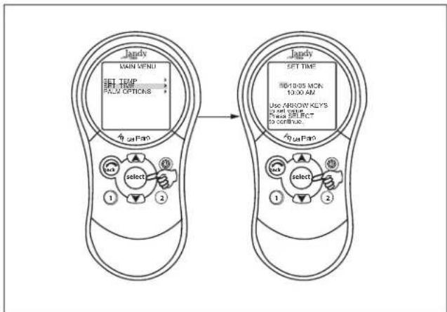
5.10 Set Time Menu
MENU > SET TIME
The SET TIME menu allows the correct time and date to be entered. The correct time and date ensures that programming will work properly.
NOTE A nine volt (9 V) battery is located at the Power Center that allows the system clock to continue to run during power outages. Ensure that the battery is checked or replaced annually.
flowchart
graph LR
    A["Main Menu"] --> B["Set Time"]
    B --> C{Set value}
    C --> D["Select"]
    D --> E["OK"]
    D --> F{Select}
    F --> G["OK"]
    style A fill:#f9f,stroke:#333
    style B fill:#ccf,stroke:#333
    style C fill:#cfc,stroke:#333
    style D fill:#fcc,stroke:#333
    style E fill:#cff,stroke:#333
    style F fill:#ffc,stroke:#333
    style G fill:#cfc,stroke:#333
Figure 21. Set Time Menu
To set the Time
Highlight MENU and press SELECT, highlight SET TIME and press SELECT. Use the UP/DOWN arrow keys to set values. Press the SELECT button to continue.
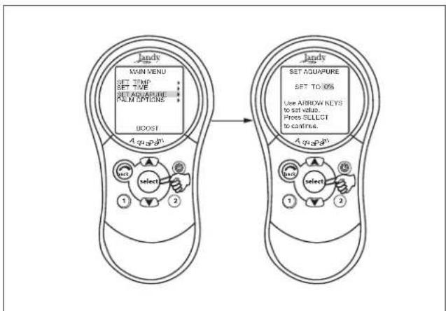
5.11 AquaPure Menu
MENU > SET AQUAPURE > SET OUTPUT%
NOTE This equipment may not be part of your system. Please check with your installer.
AquaPure Chlorine Generator system exclusively communicates with the AquaLink RS. The AquaPalm Handheld Remote will display % of chlorine output.
This menu item will only appear when an AquaPure chlorine generator is connected to the AquaLink RS system by means of the red 4-pin terminal bar.
To set the AquaPure Output Percentage (%)
Highlight MENU and press SELECT, highlight SET AQUAPURE and press SELECT. Use the UP/DOWN arrow keys to change the percentage.
See Section 5.14 for BOOST options.
NOTE When the Chlorine Generator output percentage is set to a value greater than 0 and the filter pump is on, the system salinity level and output percentage appears on the equipment status screen.
flowchart
graph LR
    A["Hand-pod 1"] --> B["select"]
    C["Hand-pod 2"] --> D["select"]
    E["Hand-pod 3"] --> F["set value"]
    G["Hand-pod 4"] --> H["set value"]
    I["Hand-pod 5"] --> J["set value"]
    K["Hand-pod 6"] --> L["set value"]
    M["Hand-pod 7"] --> N["set value"]
    O["Hand-pod 8"] --> P["set value"]
    Q["Hand-pod 9"] --> Q
    R["Hand-pod 10"] --> S["set value"]
    T["Hand-pod 11"] --> T
    U["Hand-pod 12"] --> V["set value"]
    W["Hand-pod 13"] --> W
    X["Hand-pod 14"] --> X
    Y["Hand-pod 15"] --> Y
    Z["Hand-pod 16"] --> Z
    AA["Hand-pod 17"] --> AA
    AB["Hand-pod 18"] --> AB
    AC["Hand-pod 19"] --> AC
    AD["Hand-pod 20"] --> AE["set value"]
    AF["Hand-pod 21"] --> AF
    AG["Hand-pod 22"] --> AH["set value"]
    AI["Hand-pod 23"] --> AJ["set value"]
    AK["Hand-pod 24"] --> AL["set value"]
    AM["Hand-pod 25"] --> AN["set value"]
    AO["Hand-pod 26"] --> AP["set value"]
    AQ["Hand-pod 27"] --> AR["set value"]
    AS["Hand-pod 28"] --> AT["set value"]
    AU["Hand-pod 29"] --> AV["set value"]
    AW["Hand-pod 30"] --> AX["set value"]
    AY["Hand-pod 31"] --> AZ["set value"]
    BA["Hand-pod 32"] --> BB["set value"]
    BC["Hand-pod 33"] --> BD["set value"]
    BE["Hand-pod 34"] --> BF["set value"]
    BG["Hand-pod 35"] --> BH["set value"]
    BI["Hand-pod 36"] --> BJ["set value"]
    BK["Hand-pod 37"] --> BL["set value"]
    BM["Hand-pod 38"] --> BN["set value"]
    BO["Hand-pod 39"] --> BP["set value"]
    BZ["Hand-pod 40"] --> CA["set value"]
    CB["Hand-pod 41"] --> CD["set value"]
    CE["Hand-pod 42"] --> CF["set value"]
    CG["Hand-pod 43"] --> DH["set value"]
    DI["Hand-pod 44"] --> DJ["set value"]
    DK["Hand-pod 45"] --> DE["set value"]
    FD["Hand-pod 46"] --> DF["set value"]
    DG["Hand-pod 47"] --> DG
    DH --> DH
    DD --> DH
Figure 22. Set AquaPure Menu
5.12 Auto Shut-off Menu
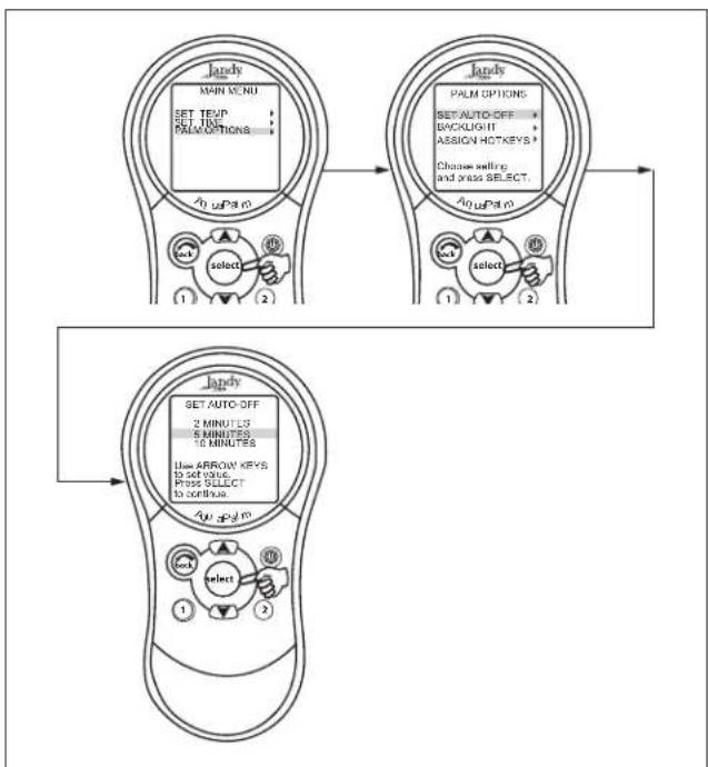
MENU > PALM OPTIONS > SET AUTO-OFF > Set Time
The AUTO-OFF feature of the handheld remote can be set to a two (2) minute, five (5) minute, or ten (10) minute auto shut off. The display can be re-enabled by pressing the Power ON/OFF button.
NOTE AquaPalm default is set to two (2) minutes.
flowchart
graph TD
    A["Main Menu"] --> B["PALM OPTIONS"]
    B --> C{SET AUTO-OFF: BACKLIGHT ASSIGN-HOT-KEYS? Choose selling and press SELECT.}
    C --> D["Select"]
    D --> E["Set AUTO-OFF: 2 MINUTES, 5 MINUTES, 10 MINUTES, Use ARROW KEYS to set value. Press SELECT to continue."]
    E --> F["Select"]
    F --> G["End"]
Figure 23. AquaPalm Options Menu - Auto-Off
To change the Auto Shut-off Time
Highlight MENU and press SELECT. Highlight PALM OPTIONS and press SELECT. Highlight SET AUTO-OFF and press SELECT. Use the UP/DOWN arrow keys to set the time out value. Then press the SELECT button to continue.
5.13 Backlight Menu
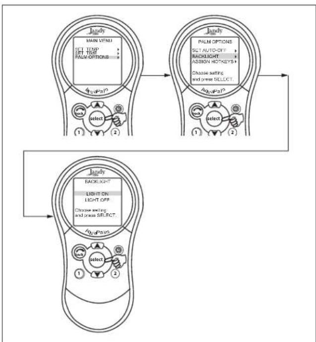
MENU > PALM OPTIONS > BACKLIGHT
The backlight can be turned on and off. Leaving the backlight turned off will extend the battery life.
NOTE Backlight default setting is set to OFF.
flowchart
graph TD
    A["Main Menu"] --> B["PALM Options"]
    B --> C{Select: SET TIME, SET TIME, PALM OPTIONS}
    C --> D["Select: 1, 2, 3, 4, 5, 6, 7, 8, 9, 10, 11, 12, 13, 14, 15, 16, 17, 18, 19, 20"]
    D --> E["Select: 1, 2, 3, 4, 5, 6, 7, 8, 9, 10, 11, 12, 13, 14, 15, 16, 17, 18, 19"]
    E --> F["Backlight"]
    F --> G{Select: SET AUTO-OFF, BACKLIGHT, ASSIGN HOTKEYS, Choose setting and press SELECT}
    G --> H["Select: 1, 2, 3, 4, 5, 6, 7, 8, 9, 10, 11, 12, 13, 14, 15, 16, 17"]
    H --> I["Select: 1, 2, 3, 4, 5, 6, 7, 8, 9, 10"]
    I --> J["Backlight"]
    J --> K{Select: SET ON, LIGHT OFF}
    K --> L["Choose setting and press SELECT"]
    L --> M["Select: 1, 2, 3, 4, 5, 6, 7, 8, 9, 10, 11, 12, 13, 14, 15, 16"]
    M --> N["Select: 1, 2, 3, 4, 5, 6, 7, 8, 9"]
Figure 24. AquaPalm Options Menu - Backlight
To change the Backlight setting
Highlight MENU and press SELECT. Highlight PALM OPTIONS and press SELECT. Highlight BACKLIGHT and press SELECT. Use the UP/ DOWN arrow keys to change the setting. Then press the SELECT button to continue.
5.14 Assign Hotkeys Menu
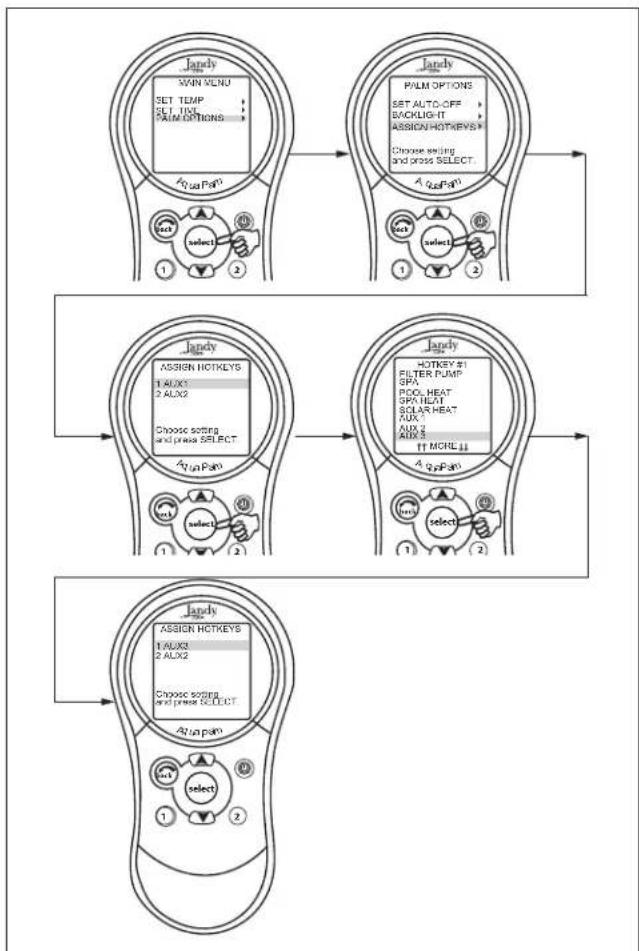
MENU > PALM OPTIONS > ASSIGN HOTKEYS > 1 or 2 > Select desired AUX
The 1 and 2 buttons on the AquaPalm Handheld Remote can be assigned to any piece of equipment connected to a circuit or relay, or a OneTouch Mood setting. This provides immediate and dedicated control of the assigned equipment.
NOTE The default setting is AUX1 for button 1 and AUX2 for button 2.
flowchart
graph TD
    A["Jandy"] --> B["MAIN MENU SET TEMP SEL TIME PAIN OPTIONS"]
    B --> C["1 select 2"]
    C --> D["Jandy"]
    D --> E["ASSIGN HOTKEYS 1 AUX3 2 AUX2"]
    E --> F["Choose setting and press SELECT"]
    F --> G["1 select 2"]
    G --> H["Jandy"]
    H --> I["ASSIGN HOTKEYS 1 AUX3 2 AUX2"]
    I --> J["Choose setting and press SELECT"]
    J --> K["1 select 2"]
    K --> L["Jandy"]
    L --> M["ASSIGN HOTKEYS 1 AUX3 2 AUX2"]
    M --> N["Choose setting and press SELECT"]
    N --> O["1 select 2"]
    O --> P["Jandy"]
    P --> Q["ASSIGN HOTKEYS 1 AUX3 2 AUX2"]
    Q --> R["Choose setting and press SELECT"]
    R --> S["1 select 2"]
    S --> T["Jandy"]
    T --> U["ASSIGN HOTKEYS 1 AUX3 2 AUX2"]
    U --> V["Choose setting and press SELECT"]
    V --> W["1 select 2"]
    W --> X["Jandy"]
Figure 25. AquaPalm Options Menu - Assign Hotkeys
To change the Hotkeys setting
Highlight MENU and press SELECT. Highlight PALM OPTIONS and press SELECT. Highlight ASSIGN HOTKEYS and press SELECT. Highlight 1 or 2 and press SELECT. Use the UP/DOWN arrow keys to change the setting. Then press the SELECT button to continue. In order to assign Hotkeys as a OneTouch Mood setting, the OneTouch Mood settings must be set up first.
5.15 Boost Menu
NOTE This equipment may not be part of your system. Please check with your installer.
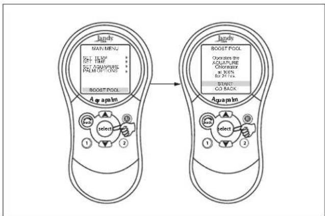
MENU > BOOST > START
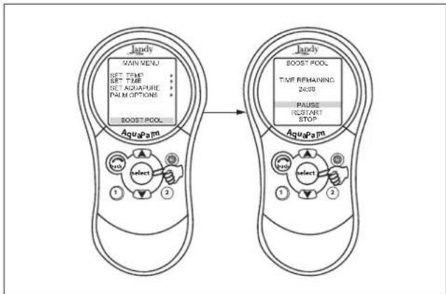
Activates the BOOST feature that will operate the AquaPure Chlorine Generator at 100% output for 24 hours. Boost mode will override all programs, all-off settings, as well as manual operation of the filter pump.
flowchart
graph LR
    A["landy"] --> B["Aqapalm"]
    B --> C["select"]
    C --> D["1"]
    C --> E["2"]
    F["landy"] --> G["Aqapalm"]
    G --> H["select"]
    H --> I["1"]
    H --> J["2"]
    K["boost POOL"] --> L["boost POOL"]
    L --> M["Activate the<br>ACAPURE<br>Choricon<br>at 30%<br>for 2474s"]
    N["START<br>CO BACK"] --> O["boost POOL"]
    O --> P["Activate the<br>ACAPURE<br>Choricon<br>at 30%<br>for 2474s"]
Figure 26. Boost Menu - Start
To use the Boost menu
Highlight MENU and press SELECT, highlight BOOST and press SELECT. Highlight START and press SELECT to begin the chlorination cycle.
Use SET AQUAPURE in MENU to set the percentage and the AQUAPURE HOURS in SYSTEM SETUP to set the hours of operation.
flowchart
graph LR
    A["Jandy MAIN MENU"] --> B["BOOST POOL"]
    C["AquApam"] --> D["boost POOL"]
    style A fill:#f9f,stroke:#333
    style C fill:#f9f,stroke:#333
    style B fill:#ccf,stroke:#333
    style D fill:#ccf,stroke:#333
Figure 27. Boost Menu - Pause or Stop
To pause or stop BOOST mode, highlight MENU and press SELECT. Highlight BOOST and press SELECT. Highlight PAUSE or STOP and press SELECT.
5.16 Battery Backup
A nine-volt battery is located at the power center. The battery keeps the clock running during a power outage so the time and date will be correct when power is restored. Programming will not be lost even if the battery is dead. Do not install the battery in the power center until the system is ready to operate. Battery will drain if power is left off.
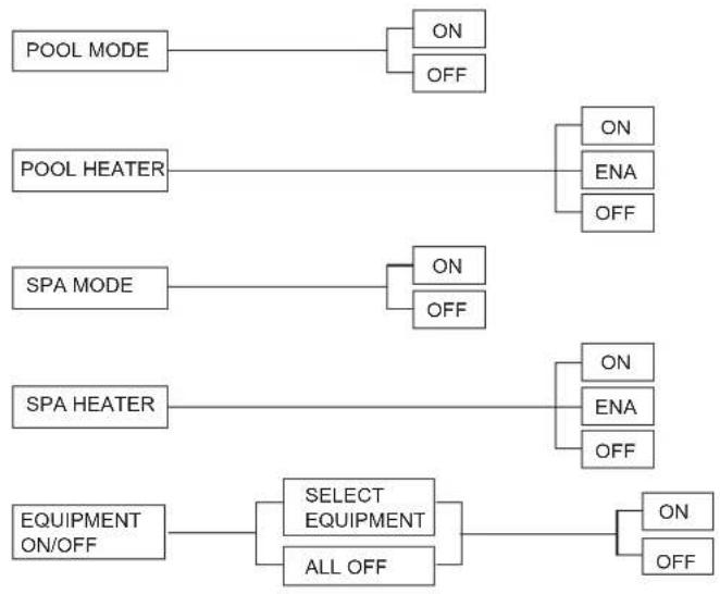
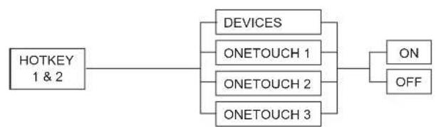
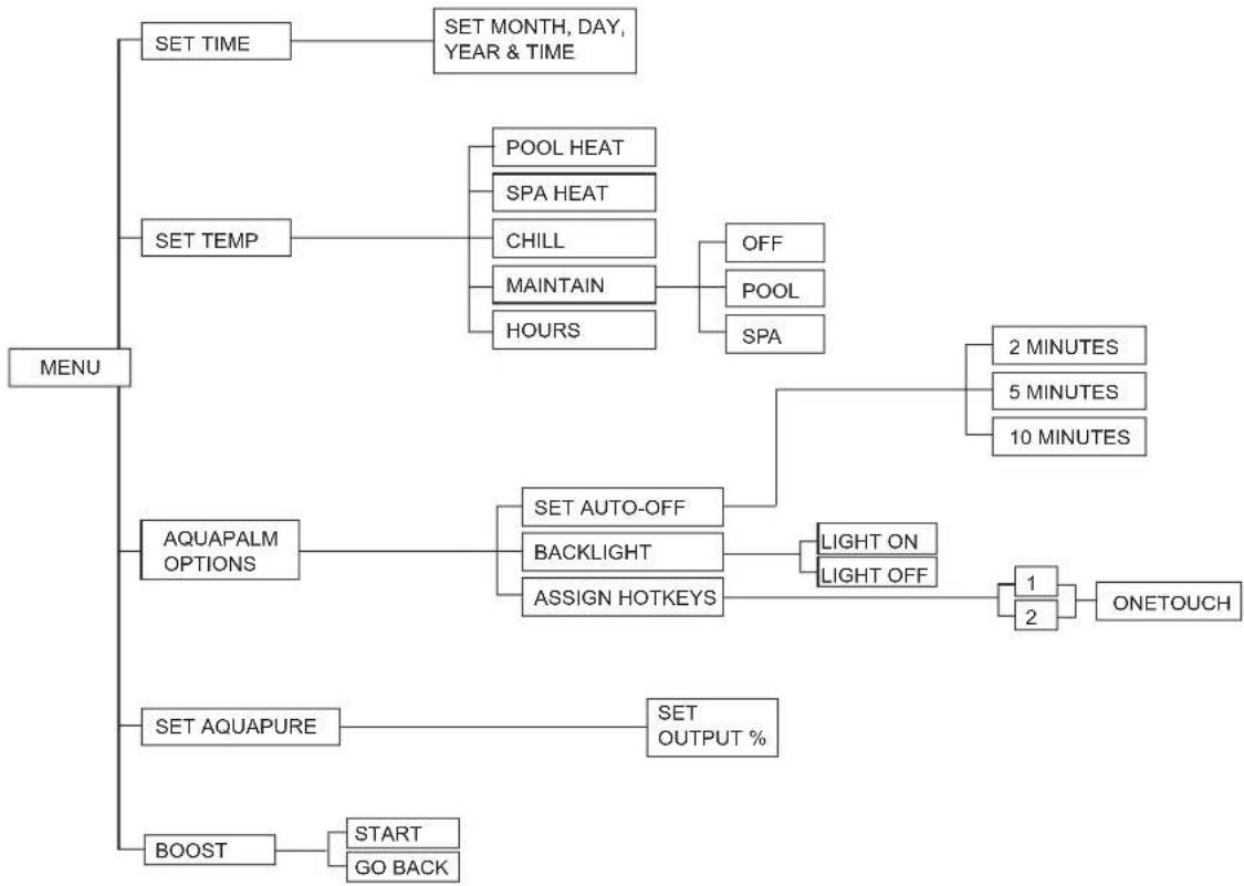
5.17 AquaPalm Handheld Remote Menu Flow Chart
flowchart
graph TD
    A["POOL MODE"] --> B["ON"]
    A --> C["OFF"]
    D["POOL HEATER"] --> E["ON"]
    D --> F["ENA"]
    D --> G["OFF"]
    H["SPA MODE"] --> I["ON"]
    H --> J["OFF"]
    K["SPA HEATER"] --> L["ON"]
    K --> M["ENA"]
    K --> N["OFF"]
    O["EQUIPMENT ON/OFF"] --> P["SELECT EQUIPMENT"]
    O --> Q["ALL OFF"]
    P --> R["ON"]
    P --> S["OFF"]
flowchart
graph LR
    A["HOTKEY 1 & 2"] --> B["ONETOUCH 1"]
    A --> C["ONETOUCH 2"]
    A --> D["ONETOUCH 3"]
    B --> E["ON"]
    C --> F["OFF"]
    D --> E
    D --> F
flowchart
graph TD
    A["MENU"] --> B["SET TIME"]
    A --> C["SET TEMP"]
    A --> D["AQUAPALM OPTIONS"]
    A --> E["SET AQUAPURE"]
    A --> F["BOOST"]
    B --> G["SET MONTH, DAY, YEAR & TIME"]
    C --> H["POOL HEAT"]
    C --> I["SPA HEAT"]
    C --> J["CHILL"]
    C --> K["MAINTAIN"]
    C --> L["HOURS"]
    H --> M["OFF"]
    H --> N["POOL"]
    H --> O["SPA"]
    D --> P["SET AUTO-OFF"]
    D --> Q["BACKLIGHT"]
    D --> R["ASSIGN HOTKEYS"]
    P --> S["LIGHT ON"]
    P --> T["LIGHT OFF"]
    S --> U["1"]
    S --> V["2"]
    T --> W["ONETOUCH"]
    U --> X["2 MINUTES"]
    V --> Y["5 MINUTES"]
    V --> Z["10 MINUTES"]
    E --> AA["SET OUTPUT %"]
    F --> AB["START"]
    F --> AC["GO BACK"]
Section 6. Troubleshooting
6.1 AquaPalm Quick Troubleshooting Guide
The AquaLink RS AquaPalm will stop communicating anytime interference (such as a 900 MHz device) prevents a valid signal transmission. When communication is lost the AquaPalm Handheld Remote will lock on the startup screen until a good link is again achieved, usually within a few seconds. If communication is not reestablished within a few seconds or if this happens often, use the troubleshooting information in the following table for suggestions.
| Symptom Problem Possible Solution | ||
| Power Center override switches operate when in Service or Time Out Mode, but the AquaPalm Handheld Remote is completely dead (no backlight on or display). | Dead batteries in the AquaPalm Handheld Remote. | Replace batteries. |
| AquaPalm Handheld Remote backlight is on and the startup screen is displayed. The override switches at the power center operate as they should. | AquaPalm is not communicating with the power center PCB. | Check the two center wires (black & yellow) of the four conductor cable to the transceiver J-box. Also check the installation of the PPD on the power center PCB. If the PPD is not seated correctly the system will not communicate. |
| AquaPalm Handheld Remote backlight is on and the startup screen is displayed, but override switches at the power center do not operate at all. | 1. Damaged or improperly installed PPD.2. Wrong PPD.3. Damaged power center PCB. | 1. Check alignment of the PPD.2. Make sure that the PPD is for an AquaPalm.3. If PPD is installed correctly, replace the power center PCB. |
| Some buttons do not operate from the AquaPalm Handheld Remote, nor from the power center override switches. | Wrong PPD chip installed at the power center PCB. | Ensure that the PPD revision number is the correct revision required for the application. |
| System locked up. Handheld frozen at WAITING screen. | Microprocessor locked. Turn off power to the system. Disconnect battery at the Power Center and turn on power. Reconnect the battery and reset time and date. | |
| Programs do not run at the correct time. | AquaLink RS does not display correct time and date. | At the AquaPalm Handheld Remote, set correct time and date. Check battery level. If LOW BATTERY is displayed, replace battery at the Power Center to ensure correct time and date are maintained. |
| LCD screen display stays on startup screen. | No communication between AquaPalm Handheld Remote and Power Center J-box. | Change the Frequency Channel. See Section 3.4. Move the Transceiver J-box closer house or under an eve. |
NOTES
LIMITED WARRANTY
Thank you for purchasing Jandy ^® pool and spa products. Jandy Pool Products, Inc. warrants all parts to be free from manufacturing defects in materials and workmanship for a period of one year from the date of retail purchase, with the following exceptions:
- AquaLink® RS units installed with Jandy Surge Protection Kits will be covered for two years.
- NeverLube® valves are warranted for the life of pool and/or spa on which they were originally installed.
- AquaPure™ Electronic Chlorine Generator Electrolytic Cells carry a 5 year limited warranty on a prorated basis.
This warranty is limited to the first retail purchaser, is not transferable, and does not apply to products that have been moved from their original installation sites. The liability of Jandy Pool Products, Inc. shall not exceed the repair or replacement of defective parts and does not include any costs for labor to remove and reinstall the defective part, transportation to or from the factory, and any other materials required to make the repair. This warranty does not cover failures or malfunctions resulting from the following:
- Failure to properly install, operate or maintain the product(s) in accordance with our published Installation, Operation and Maintenance Manuals provided with the product(s).
- The workmanship of any installer of the product(s).
- Not maintaining a proper chemical balance in your pool and/or spa [pH level between 7.2 and 7.8, Total Alkalinity (TA) between 80 to 120 ppm, Total Dissolved Solids (TDS) less than 2000 not including salt ppm].
- Abuse, alteration, accident, fire, flood, lightning, rodents, insects, negligence or acts of God.
- Scaling, freezing, or other conditions causing inadequate water circulation.
- Operating the product(s) at water flow rates outside the published minimum and maximum specifications.
- Use of non-factory authorized parts or accessories in conjunction with the product(s).
- Chemical contamination of combustion air or improper use of sanitizing chemicals, such as introducing sanitizing chemicals upstream of the heater and cleaner hose or through the skimmer.
- Overheating; incorrect wire runs; improper electrical supply; collateral damage caused by failure of O-Rings, DE grids, or cartridge elements; or damage caused by running the pump with insufficient quantities of water.
LIMITATION OF LIABILITY:
This is the only warranty given by Jandy Pool Products, Inc. No one is authorized to make any other warranties on behalf of Jandy Pool Products, Inc. THIS WARRANTY IS IN LIEU OF ALL OTHER WARRANTIES, EXPRESSED OR IMPLIED, INCLUDING BUT NOT LIMITED TO ANY IMPLIED WARRANTIES OF FITNESS FOR A PARTICULAR PURPOSE AND MERCHANTABILITY. JANDY POOL PRODUCTS, INC. EXPRESSLY DISCLAIMS AND EXCLUDES ANY LIABILITY FOR CONSEQUENTIAL, INCIDENTAL, INDIRECT OR PUNITIVE DAMAGES FOR BREACH OF ANY EXPRESSED OR IMPLIED WARRANTY. This warranty gives you specific legal rights. You may also have other rights which vary by state or province.
WARRANTY CLAIMS:
For prompt warranty consideration, contact your dealer and provide the following information: proof of purchase, model number, serial number and date of installation. The installer will contact the factory for instructions regarding the claim and to determine the location of the nearest designated service center. If the dealer is not available, you can locate a service center in your area by visiting www.jandy.com or by calling our technical support department at (707) 776-8200 extension 260. All returned parts must have a Returned Material Authorization number to be evaluated under the terms of this warranty.
- Installation and Operation Manual
- AquaPalm
- WARNING
- ATTENTION
- Table of Contents
- EQUIPMENT INFORMATION RECORD
- Section 1. Important Safety Instructions
- READ AND FOLLOW ALL INSTRUCTIONS
- LIRE LA NOTICE TECHNIQUE.
- DANGER
- To Reduce the Risk of Injury -
- AVERTISSEMENT
- CAUTION
- Section 2. Product Description
- Basic Functions
- AquaPalm Handheld Remote and Transceiver J-box Dimensions
- Section 3. Installation
- AquaPalm Transceiver J-Box Cable Connection to Power Center PCB
- AquaPalm Transceiver J-box Installation
- AquaPalm Handheld Remote Installation
- Changing the Frequency Channel
- Section 4. AquaPalm Handheld Remote Operation
- Basic Functions
- Using the Buttons
- Battery Status
- Signal Strength
- Section 5. AquaPalm Handheld Remote Menus
- Pool Mode/Spa Mode
- Equipment On/Off Menu
- EQUIPMENT ON/OFF > ALL OFF
- To use Equipment On/Off
- Filter Pump (Pool Mode)
- EQUIPMENT ON/OFF > FILTER PUMP
- To use Filter Pump
- Spa
- EQUIPMENT ON/OFF > SPA
- To use Spa
- Pool Heat
- EQUIPMENT ON/OFF > FILTER PUMP > POOL HEAT > (Set to Desired Temperature)
- To use Pool Heat
- Spa Heat
- EQUIPMENT ON/OFF > SPA > SPA HEAT > (Set to Desired Temperature)
- To use Spa Heat
- Solar Heat
- EQUIPMENT ON/OFF > SOLAR HEAT
- To use Solar Heat
- Auxiliary Equipment
- EQUIPMENT ON/OFF > AUX (Select desired Aux)
- To turn an Auxiliary On or Off
- Set Temperature Menu
- MENU > SET TEMP > POOL or SPA > SET TEMP VALUE
- To set Pool/Spa Temperatures
- Set Time Menu
- MENU > SET TIME
- To set the Time
- AquaPure Menu
- MENU > SET AQUAPURE > SET OUTPUT%
- To set the AquaPure Output Percentage (%)
- Auto Shut-off Menu
- MENU > PALM OPTIONS > SET AUTO-OFF > Set Time
- To change the Auto Shut-off Time
- Backlight Menu
- MENU > PALM OPTIONS > BACKLIGHT
- To change the Backlight setting
- Assign Hotkeys Menu
- MENU > PALM OPTIONS > ASSIGN HOTKEYS > 1 or 2 > Select desired AUX
- To change the Hotkeys setting
- Boost Menu
- MENU > BOOST > START
- To use the Boost menu
- Battery Backup
- AquaPalm Handheld Remote Menu Flow Chart
- Section 6. Troubleshooting
- AquaPalm Quick Troubleshooting Guide
- LIMITED WARRANTY
- LIMITATION OF LIABILITY:
- WARRANTY CLAIMS:
Brand : Jandy
Model : AquaLink Wireless Remote
Category : Wireless remote