
AquaLink Touch - Home Automation Jandy - Free user manual and instructions
Find the device manual for free AquaLink Touch Jandy in PDF.


| Product Type | Home Automation Controller for Pool/Spa |
| Model | AquaLink Touch (Jandy) |
| Display | Color LCD Touch Screen (approx. 7-8 inch diagonal) |
| Dimensions (Wall Flush-Mount) | 8 in x 6 in x 1.5 in (20.3 cm x 15.2 cm x 3.8 cm) |
| Weight | Approx. 1 lb (0.45 kg) |
| Power Source (Wired) | 5V DC from Power Center (via RS-485) |
| Power Source (Wireless) | Rechargeable battery pack |
| Battery Charger | Provided with wireless unit (charging base) |
| Indoor Use Only | Not weatherproof or waterproof |
| Maximum Controllers per System | 4 (each with unique address) |
| Screen Brightness | Adjustable 10% to 100% (default 80%) |
| Sound Feedback | Enable/disable (default enabled) |
| RF Channel (Wireless Only) | Selectable to avoid interference |
| Scheduling | Program ON/OFF times for circuits (multiple per day) |
| Temperature Control | Set pool/spa temperature (34°F to 104°F) |
| OneTouch Scenes | Up to 6 preset mood/scene settings |
| Photo Slideshow | Yes, from memory card (MS, MMC, SD, XD) or internal memory (256 MB) |
| Lockout/Password | 4-digit password for system, programs, devices |
| Compatible Systems | AquaLink RS with Rev Q firmware or later |
| Supported Equipment | Filter pump, heater, spa, lights, chlorinator, sprinklers, etc. |
| Screen Cleaning | Use dry soft cloth (microfiber); avoid ammonia, alcohol, acetone |
| Safety Features | Freeze protection, heater cool-down delay, lockouts |
Frequently Asked Questions - AquaLink Touch Jandy
User questions about AquaLink Touch Jandy
0 question about this device. Answer the ones you know or ask your own.
Ask a new question about this device
Download the instructions for your Home Automation in PDF format for free! Find your manual AquaLink Touch - Jandy and take your electronic device back in hand. On this page are published all the documents necessary for the use of your device. AquaLink Touch by Jandy.
USER MANUAL AquaLink Touch Jandy
natural_image
Exterior view of a modern rectangular electronic device with a dark screen and white frame (no text or symbols visible)AquaLink® Touch™
Wired/Wireless Controller
(For use with AquaLink RS for Systems with Rev Q Firmware or later)
FOR INDOOR USE ONLY
WARNING
FOR YOUR SAFETY - This product must be installed and serviced by a contractor who is licensed and qualified in pool equipment by the jurisdiction in which the product will be installed where such state or local requirements exist. In the event no such state or local requirement exists, the maintainer must be a professional with sufficient experience in pool equipment installation and maintenance so that all of the instructions in this manual can be followed exactly. Before installing this product, read and follow all warning notices and instructions that accompany this product. Failure to follow warning notices and instructions may result in property damage, personal injury, or death. Improper installation and/or operation will void the warranty.
Improper installation and/or operation can create unwanted electrical hazard which can cause serious injury, property damage, or death.
ATTENTION
This device complies with part 15 of the FCC Rules. Operation is subject to the following two conditions: (1) This device may not cause harmful interference, and (2) this device must accept any interference received, including interference that may cause undesired operation.
NOTE: This equipment has been tested and found to comply with the limits for a Class B digital device, pursuant to part 15 of the FCC Rules. These limits are designed to provide reasonable protection against harmful interference in a residential installation. This equipment generates, uses and can radiate radio frequency energy and, if not installed and used in accordance with the instructions, may cause harmful interference to radio communications. However, there is no guarantee that interference will not occur in a particular installation. If this equipment does cause harmful interference to radio or television reception, which can be determined by turning the equipment off and on, the user is encouraged to try to correct the interference by one or more of the following measures:
- Reorient or relocate the receiving antenna.
- Increase the separation between the equipment and receiver.
- Connect the equipment to an electrical source on a circuit different from that to which the receiver is connected.
- Consult the dealer or an experienced radio/TV technician for help.
Modifications made to this equipment, which are not authorized by the manufacturer, may void the user's authority to operate this equipment.
Table of Contents
NOTE Some of the features described in this Manual DO NOT apply to all AquaLink RS models.
Section 1. Important Safety Instructions ..... 6
Section 2. Overview of the AquaLink Touch Controller....8
2.1 System Overview
2.2 Basic Functions
2.2.1 Turning ON the AquaLink Touch .....9
2.2.2 Turning OFF the AquaLink Touch .....9
2.3 Battery Status for Wireless Controller .....9
2.4 Signal Strength for Wireless Controller .....9
2.5 Maintenance Information
Section 3. Using the Home Screen Menu .. 10
3.1 Home Screen
3.1.1 Title Bar....10
3.1.2 Middle Info Panel 10
3.1.3 Navigation Bar....11
3.2 Dialog Boxes....11
Section 4. Using the Menu Screen .....11
4.1 Menu Screen.... 11
4.1.1 To Display the Menu Screen 11
4.2 Schedule 11
4.2.1 Adding Devices to the Circuit List .....12
4.2.2 ON/OFF Times 12
4.3 Set Temperature (For Pool and Spa Only System)....13
4.3.1 Pool Heat 13
4.3.2 Spa Heat
4.3.3 Chiller....13
4.4 To Set Up Date/Time 14
4.4.1 Date....14
4.4.2 Time 14
4.5 Customize Home
4.5.1 Customize General, Aux and OneTouch Items 14
4.6 Lockouts Password....15
4.6.1 To Lockout Devices 15
4.6.2 To Set Lockout Password 15
4.6.3 How to Use the System when a Password is Enabled 15
4.7 AquaPure ^® .....16
4.7.1 To Set Up Pool/Spa....16
4.7.2 To Set Up Quick Boost 16
4.7.3 To Pause, Restart and Stop Quick Boost..17
4.7.4 Boost Setup....17
4.8 Touch Setup
4.8.1 Brightness 18
4.8.2 Sound 18
4.8.3 Calibrate AquaLink Touch....18
4.8.4 Address....19
4.8.5 RF Channel (For wireless units only) .....19
4.8.6 AquaLink Touch J-Box LED Operation .....20
4.9 Program Group 20
4.9.1 A and B Groups....21
4.9.2 Program Auto Switch....21
8 4.9.3 Custom Label Group ......21
9 4.9.4 Custom Label....21
Section 5. Using the OneTouch Menu ..... 22
5.1 OneTouch 22
5.2 Spa Mode....22
5.3 All Off 23
Section 6. Using the Help Menu.... 23
6.1 Help Menu....23
6.2 Help Sensors 23
6.3 Help Remotes 24
6.4 Help Errors....24
Section 7. Using the Status Menu ...... 24
7.1 Status Menu 24
Section 8. Using the Photos Menu ...... 25
8.1 Creating a Slideshow 25
8.2 Inserting a Memory Card .....25
8.3 Importing and Deleting Digital Photos.....25
8.4 Slideshow Setup 25
8.4.1 To Enable Slideshow....26
8.4.2 Image Time 26
8.4.3 Sleep Mode and Sleep Time 26
8.4.4 No Activity 26
Section 9. Using Other Devices ON/OFF ... 27
9.1 Using Other Devices On/Off 27
9.2 Filter Pump 27
9.3 Spa 28
9.4 Pool Heat 28
9.5 Spa Heat (Dual Equipment) 28
9.6 Solar Heat 28
9.7 Auxiliary Equipment 29
9.8 Using Color Lights....29
9.9 TEMP1 / TEMP2 (Pool or Spa Only) .....30
9.9.1 To Set Up TEMP1....30
9.9.2 To Set Up TEMP2 (For Pool and Spa Only System)....30
9.10 Two Speed Operation (*Not Available for Export Models*) 31
9.10.1 Two Speed Manual Operation ....31
9.10.2 High Speed Filtration Pump 31
9.10.3 Low Speed Filtration Pump 31
Section 10. System Setup .... 32
10.1 System Setup Screen 32
10.1.1 To Access System Setup 32
10.2 Label Auxiliary Functions ....3
10.2.1 To Set Up Label Auxiliary ....32
10.3 Color Lights 33
10.3.1 To Set Up Color Lights 33
10.4 ESP Link (Seasonal Adjust) 33
10.4.1 To Set Up Seasonal Adjust 34
10.4.2 ESP Link Operation 34
10.5 Set Dimmers ......34
10.5.1 To Set Dimmers .....34
10.6 OneTouch 35
10.6.1 Select Devices 35
10.6.2 Select Name 35
10.7 Spa Remotes 35
10.7.1 Spa Side Switch 36
10.7.2 SpaLink® Setup 36
10.8 Device Runtime 37
10.8.1 To Set Up Device Runtime 37
10.9 Maintain Temp 37
10.9.1 To Set Up Maintain Temp 37
10.10 RS InterLink 38
10.10.1 To Set Up RS Intelink 38
10.11 Freeze Protection....38
10.11.1 To Set Up Freeze Protection ....38
10.13.2 City/Time Zone 40
10.13.3 Assign Devices....40
10.14 All Off Time 40
10.14.1 To Set Up All Off Time 40
10.15 Pump Lockout 41
10.15.1 To Set Up Pump Lockout 41
10.16 Daylight Savings Time (DST)....41
10.16.1 To Set Up DST 41
10.17 Product Information....41
10.17.1 Customize Product and Service Info......41
10.17.2 Customize Service Phone....42
10.18 Air Temperature 42
10.18.1 To Set Up Air Temperature 42
10.19 Temp Calibration 42
10.19.1 To Set Up Calibration 42
10.20 Degrees C/F 42
10.20.1 To Set Up Degrees....43
10.21 In-Floor Cleaning 43
10.21.1 To Set Up In Floor Cleaning 43
10.22 Clear Memory 43
10.22.1 To Set Up Clear Memory 43
10.23 Cancel Delay....44
Section 11. Heat Pump Setup .... 44
11.1 Solar Priority/Heat Pump Priority .....44
11.2 Heat Pump (Heat Mode) 44
2 11.2.1 Heat Pumps Controlled by Extra Aux/Solar Boost Relay....45
11.2.2 Heat Pumps Controlled by the RS485 Interface 45
11.2.3 Heat Mode....45
11.3 Heat Pump (Chiller Mode) 46
11.3.1 Heat Pumps (Chiller) Controlled by the Extra Aux/Solar Boost Relay .....46
11.3.2 Heat Pumps (Chiller) Controlled by the RS485 Interface 46
11.3.3 Chill Mode 46
Section 12. Variable Speed Pump Setup ..... 47
12.1 To Select the Pump/Model .....47
12.2 To Set Up the Pump Application .....48
12.3 To Set Up MIN/MAX Parameters .....48
12.4 To Set Up the Priming Speed .....48
12.5 To Set Up the Priming Duration Time .....49
12.6 To Assign a Pump Speed to an AUX .....49
12.7 To Set Up Pump Speed 49
12.8 To Re-label the Speed Preset .....49
12.9 Default Preset Speed Labels (RS Combo and RS only) 50
12.9.1 Default Preset Speed Labels (Dual Equipment)....51
Section 13. Sprinkler System Setup .... 52
13.1 Running the Sprinkler System ....52
13.1.1 Cancel Today - 24 Hour Sprinkler Delay ...52
13.1.2 Enabling the Sprinkler System ....52
13.1.3 Manually Starting a Sprinkler Program .....53
13.1.4 Disabling the Sprinkler System ....53
13.2 Programming Sprinkler System ....53
13.2.1 To Set Up the Water Days 54
13.2.2 To Set Up the Sprinklers Program Start Time menu ....54
13.2.3 To Set Up the Sprinkler Valve Duration Time 54
Section 14. ChemLink™ Setup .... 55
14.1 To Set Up the ChemLink .....55
14.2 To Configure the ORP Controller .....55
14.2.1 ORP Feeder Type 56
14.2.2 ORP Feeder Times....56
14.2.3 ORP Delay On Time 56
14.2.4 ORP Setpoint 56
14.2.5 ORP Alarm - High Alert....57
14.2.6 ORP Alarm - Low Alert 57
14.2.7 Wait or Stop pH....57
14.2.8 ORP Next Cleaning....58
14.3 To Configure the pH Controller .....58
14.3.1 pH Feeder Type....58
14.3.2 pH Feeder Times 58
14.3.3 pH Delay On Time 59
14.3.4 pH Setpoint 59
14.3.5 pH Alarm - High Alert 59
14.3.6 pH Alarm - Low Alert 59
14.3.7 pH Acid or Base Feed 60
14.3.8 pH Next Cleaning 60
14.3.9 pH Next Calibration 60
14.3.10 pH Calibration 60
14.4 Manual Feed Activation 61
14.4.1 To Perform an ORP Manual Feed .....61
14.4.2 To Perform a pH Manual Feed .....61
14.4.3 To Enable the ChemLink™ Feeder Tank Level Switch 61
Section 15. Glossaries ...... 62
15.1 Safety Delays and Lockouts ....62
15.2 Special Auxiliary Labels 62
15.3 Controller Messages....63
Section 16. AquaLink Touch Menu Flow Chart....64
EQUIPMENT INFORMATION RECORD
DATE OF INSTALLATION ____
INSTALLER INFORMATION
INITIAL PRESSURE GAUGE READING (WITH CLEAN FILTER)
PUMP MODEL
FILTER MODEL
CONTROL PANEL MODEL
NOTES:
HORSEPOWER
SERIAL NUMBER
SERIAL NUMBER
Section 1. Important Safety Instructions
READ AND FOLLOW ALL INSTRUCTIONS Lire la notice technique.
All electrical work must be performed by a licensed electrician and conform to all national, state, and local codes. When installing and using this electrical equipment, basic safety precautions should always be followed, including the following:

DANGER
To reduce the risk of injury, do not remove the suction fittings of your spa or hot tub. Never operate a spa or hot tub if the suction fittings are broken or missing. Never replace a suction fitting with one rated less than the flow rate marked on the equipment assembly.

WARNING
Prolonged immersion in hot water may induce hyperthermia. Hyperthermia occurs when the internal temperature of the body reaches a level several degrees above the normal body temperature of 98.6^ F ( 37^ C). The symptoms of hyperthermia include dizziness, fainting, drowsiness, lethargy, and an increase in the internal temperature of the body. The effects of hyperthermia include: 1) unawareness of impending danger; 2) failure to perceive heat; 3) failure to recognize the need to exit spa; 4) physical inability to exit spa; 5) fetal damage in pregnant women; 6) unconsciousness resulting in a danger of drowning.

WARNING
To Reduce the Risk of Injury -
a) The water in a spa should never exceed 104^ F ( 40^ C). Water temperatures between 100^ F ( 38^ C) and 104^ F ( 40^ C) are considered safe for a healthy adult. Lower water temperatures are recommended for young children and when spa use exceeds 10 minutes.
b) Since excessive water temperatures have a high potential for causing fetal damage during the early months of pregnancy, pregnant or possibly pregnant women should limit spa water temperatures to 100^ F ( 38^ C).
c) Before entering a spa or hot tub, the user should measure the water temperature with an accurate thermometer since the tolerance of water temperature-regulating devices varies.
d) The use of alcohol, drugs, or medication before or during spa or hot tub use may lead to unconsciousness with the possibility of drowning.
e) Obese persons and persons with a history of heart disease, low or high blood pressure, circulatory system problems, or diabetes should consult a physician before using a spa.
f) Persons using medication should consult a physician before using a spa or hot tub since some medication may induce drowsines while other medication may affect heart rate, blood pressure, and circulation.

WARNING
Risk of electric shock - Install the power center at least five (5) feet (1,52m) from the inside wall of the pool and/or hot tub using non-metallic plumbing. Canadian installations must be at least three (3) meters from the water. Children should not use spas or hot tubs without adult supervision.
Do not use spas or hot tubs unless all suction guards are installed to prevent body and hair entrapment.
People using medications and/or having an adverse medical history should consult a physician before using a spa or hot tub.

AVERTISSEMENT
People with infectious diseases should not use a spa or hot tub.
To avoid injury, exercise care when entering or exiting the spa or hot tub.
Do not use drugs or alcohol before or during the use of a spa or hot tub to avoid unconsciousness and possible drowning.
Pregnant or possibly pregnant women should consult a physician before using a spa or hot tub.
Water temperature in excess of 100^ F ( 38^ C) may be injurious to your health.
Before entering a spa or hot tub, measure the water temperature with an accurate thermometer.
Do not use a spa or hot tub immediately following strenuous exercise.
Prolonged immersion in a spa or hot tub may be injurious to your health.
Do not permit any electric appliance (such as a light, telephone, radio, or television) within five (5) feet (1,52m) of a spa or hot tub.
The use of alcohol, drugs or medication can greatly increase the risk of fatal hyperthermia in hot tubs and spas.
Water temperature in excess of 100^ F ( 38^ C) may be hazardous to your health.
AVERTISSEMENT
To avoid injury ensure that you use this control system to control only packaged pool/spa heaters which have built-in operating and high limit controls to limit water temperature for pool/spa applications. This device should not be relied upon as a safety limit control.
WARNING
A terminal bar marked "GROUND" is provided within the power center. To reduce the risk of electrical shock which can cause serious injury or death, connect this terminal bar to the grounding terminal of your electric service or supply panel with a continuous copper conductor having green insulation and one that is equivalent in size to the circuit conductors supplying this equipment, but no smaller than no. 12 AWG (3,3mm ^2 ). In addition, a second wire connector should be bonded with a no. 8 AWG (8,4mm ^2 ) copper wire to any metal ladders, water pipes, or other metal within five (5) feet (1,52 m) of the pool/spa. In Canada the bonding wire must be minimum 6 AWG (13,3mm ^2 ).
WARNING
Only use the battery pack provided with the equipment. Only use the battery charger provided with the equipment. RISK OF EXPLOSION IF BATTERY IS REPLACED BY AN INCORRECT TYPE.
CAUTION
A ground-fault circuit-interrupter must be provided if this device is used to control underwater lighting fixtures. The conductors on the load side of the ground-fault circuit-interrupter shall not occupy conduit, boxes, or enclosures containing other conductors unless the additional conductors are also protected by a ground-fault circuit-interrupter. Refer to local codes for complete details.

Attention installer: Install to provide drainage of compartment for electrical components.
Section 2. Overview of the AquaLink Touch Controller
Welcome, and thank you for purchasing the AquaLink Touch Controller!
The AquaLink Touch Controller is a state-of-the-art fully configurable touch-sensitive panel. It's an ideal modern and stylish panel to control pool, spa, sprinklers, salt chlorinators and other equipment -- all in one compact package.
NOTE The AquaLink Touch controller is for indoor use only. The controller is not weather proof or water proof.
This document gives in struc tions for operating the Jandy AquaLink Touch Controller. Theinstructions must be fol lowed exactly. Read through the instructions com plete ly before operating the equipment.
2.1 System Overview
The AquaLink RS AquaLink Touch controller can be used in addition to an already existing AquaLink RS control system, however, the firmware in the Power Center must be updated to revision Q or later. The AquaLink Touch controller is an in-wall or hand-held color touch screen that by default comes with a basic setup.
The AquaLink Touch controller is a scalable system that may be customized to integrate home automation solutions in any of the following ways:
- Activate the equipment manually through the DEVICES menu.
- Program the equipment to turn on and off at specific times.
- Use the OneTouch buttons to create scene settings with just "one touch" of a button. For example, you can program the spa heater to heat to 101 degrees, spa light on, jets on, water features on, and then name the result Romantic Scene.
Additionally, the AquaLink Touch case comes with a flash memory card reader where you import your favorites digital photos to create your own custom slideshow.
See Section 8.1, "Creating a Slideshow".
NOTE Memory cards supported include memory stick (MS), multimedia cards (MMC), secure digital (SD), and XD picture cards (XD).
NOTE The wireless controller is not weather proof or water proof.
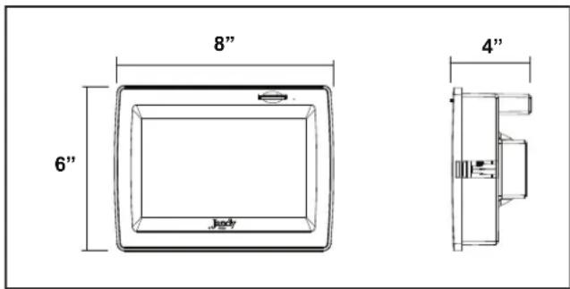
Figure 1. Wall Flush-Mount AquaLink Touch Controller
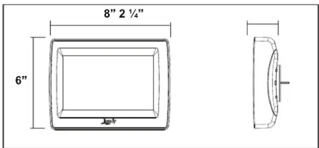
Figure 2. Wall Surface-Mount AquaLink Touch Controller
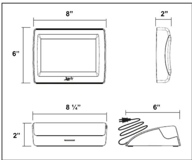
Figure 3. Wireless AquaLink Touch Controller with Charging Base.
2.2 Basic Functions
The AquaLink Touch controller is operated by touching the screen with the tip of your finger or you may use a stylus pen or similar device. When the screen is touched, an optional "keyclick" provides audible feedback.
The default setting for the sound is ENABLED.
See Section 4.8.2, "Sound".

CAUTION
To prevent damage to the screen, lightly touch the screen with the tip finger. Do not use any other type of objects other than the finger or a stylus to touch the screen.
DO NOT use metal or hard pointed devices that might scratch or damaged the LCD screen.
2.2.1 Turning ON the AquaLink Touch
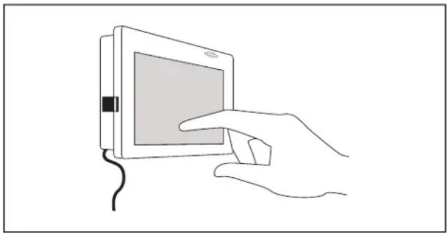
To turn on the wireless AquaLink Touch controller, touch anywhere on the LCD screen for two (2) seconds and the screen will be lit. You will hear a beep sound. For a wired AquaLink Touch controller, a momentary touch will awaken a unit that has gone sleep.
natural_image
Line drawing of a hand holding a tablet device with a mouse, no text or symbols presentFigure 4. Turning ON the AquaLink Touch
2.2.2 Turning OFF the AquaLink Touch
To turn off the AquaLink Touch controller, touch the POWER button on the bottom navigation bar and a CONFIRM dialog box will appear. Touch the OK button to turn off the AquaLink Touch.
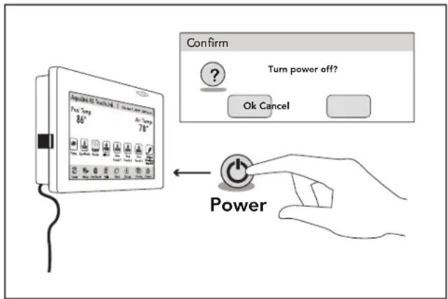
Figure 5. Turning OFF the AquaLink Touch
2.3 Battery Status for Wireless Controller
The Battery icon ▪ located on the top middle of the HOME menu screen, indicates the status of the battery. If the batteries have full or sufficient charge, the icon will appear on the display screen as 100%, 75%, 50%, or 25% full. If the battery needs to be charged, the icon will consistently blink and appear as □ and the display will sound a warning signal.
2.4 Signal Strength for Wireless Controller
The Signal Strength icon Y located on the top of the HOME menu screen, indicates the signal strength available from the transceiver J-box to the AquaLink Touch controller. Signal strength is affected (lowered) as the AquaLink Touch controller is moved farther away from the transceiver J-Box.
Also, obstructions, such as walls or other wireless products, can lower the signal strength if located between the AquaLink Touch controller and the transceiver J-Box.
2.5 Maintenance Information
The AquaLink Touch screen can be easily scratched and damaged. This type of screen requires special care when cleaning. Follow the steps below to safely clean the AquaLink Touch screen:
- Turn off the screen. If the screen is dark, it will be easier to see the areas that are dirty or oily.
- Use a dry, soft cloth and very gently wipe the screen. A great choice would be the microfiber type of cloth used to clean eyeglasses.

CAUTION
Avoid using paper towels, tissue paper, or something like your shirt to wipe the LCD screen. These non-ultrasoft materials can easily scratch the screen.
- If the dry cloth did not completely remove the dirt or oil, do not press harder in an attempt to scrub it off.
- Many companies also sell small spray bottles of special cleaner for LCD screens. Spray cleaner may also be used by applying to a dry, soft cloth.

CAUTION
Avoid cleaning products that contain ammonia, ethyl alcohol, acetone, toluene, ethyl acid, or methyl chloride. These chemicals can react with the materials that the LCD screen is made of which could yellow the screen or cause other kinds of damage.
- The plastic case that surrounds the screen can be cleaned with any multipurpose cleaner but take care to avoid contact with the screen itself. Never spray liquid directly on the LCD screen or it could run inside the monitor and cause damage.
Section 3. Using the Home Screen Menu
3.1 Home Screen
Initially, when the AquaLink Touch controller is turned on, the HOME screen appears. This screen functions primarily as the logon screen and starting point for each session, providing access to the main navigation bar. This screen displays the current time, date, temperature, and some user defined features.
As shown in the figure below, the AquaLink Touch menu screen displays the following layout:
The title bar.
- The middle info panel.
- The navigation bar.
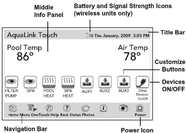
3.1.1 Title Bar
The title bar displays the title of the screen and the current date/time. The title of the current menu in use will always be shown on the title bar. This portion of the screen is a read only bar and does not respond to touch.
NOTE For wireless controllers, a battery status and signal strength are shown in the HOME screen title bar.
3.1.2 Middle Info Panel
The middle info panel on the HOME screen displays temperature, user defined features and access to the OTHER DEVICES ON/OFF screen.
3.1.3 Navigation Bar
The navigation bar displays the following links:
HOME Returns the user to HOME screen.
MENU Displays the main menu setup and programming.
ONETOUCH Turns on/off preset mood/scene settings.
HELP Displays the service and equipment information.
BACK Returns the user to the previous screen.
STATUS Displays information about the equipment.
PHOTOS Displays the slideshow program and setup.
POWER Turns off the controller.
3.2 Dialog Boxes
These are secondary windows that provide additional information or alerts about an operation in progress.
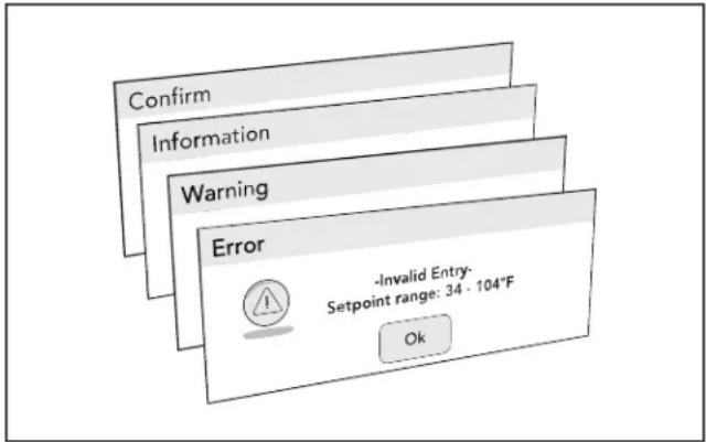
CONFIRM Asks if the user wants to proceed with an action.
INFORMATION
Informs the user of events that are related to the current user activity.
WARNING Alerts the user of a condition that might cause a problem.
ERROR Alerts the user of an error.
Section 4. Using the Menu Screen
4.1 Menu Screen
The MENU screen provides access to the main links to program, setup, schedule, and customize your pool/spa system.
4.1.1 To Display the Menu Screen
HOME > MENU
From the HOME screen, touch the MENU button to display the main MENU screen.
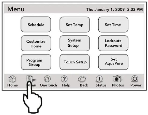
4.2 Schedule
The SCHEDULE screen allows ON and OFF times to be programmed for any circuit (equipment) controlled by the AquaLink RS. The circuit can be scheduled to turn ON or OFF all days, weekends, weekdays, or any specific day of the week. Circuit are not listed in the SCHEDULE box until a START and STOP time are entered.
Each piece of equipment can be programmed for multiple on/off times each day. The SCHEDULE screen displays each circuit schedule list and a run days, START and STOP time, along with run days.
Use the PAGE UP/DOWN to scroll the circuit list. Select the RUN DAYS, then set the START and STOP times.
4.2.1 Adding Devices to the Circuit List
Adding new devices to the circuit list on the SCHEDULE screen is a two-steps procedure. First, you select and add the device to the circuit list and then you program it as desired.
First Step - Selecting the new device
MENU > SCHEDULE > SCHEDULE DEVICES
From the SCHEDULE screen, in the circuit schedule list, touch the NEW button to display the screen below.
From the SCHEDULE DEVICES screen, in the DEVICES list, touch the desired equipment. Then, touch the SELECT button to save your selection and you will be automatically returned to the SCHEDULE screen.
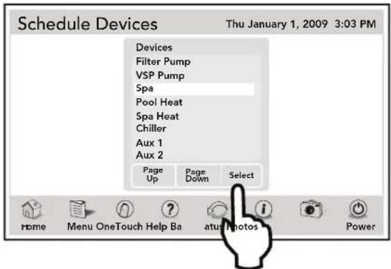
Use PAGE UP/DOWN to scroll the devices list.
NOTE Only one piece of equipment can be selected at a time.
Second Step - Programming the new device
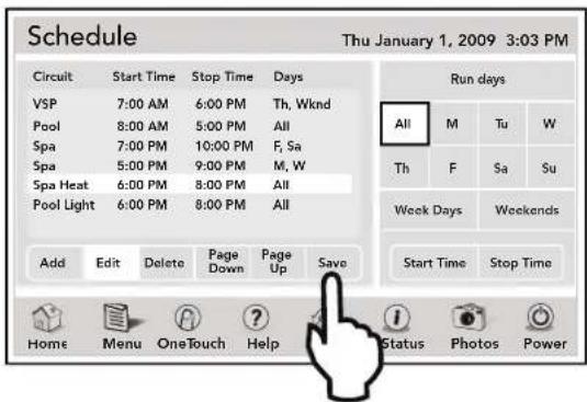
On the SCHEDULE screen, the added equipment will be displayed and highlighted in the circuit list. Also, the EDIT will be highlighted.
Enter the day for the new device. Touch SAVE when finished. Repeat this procedure to add more devices to the circuit list.
4.2.2 ON/OFF Times
MENU > SCHEDULE
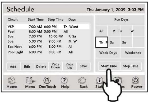
From the SCHEDULE screen, in the circuit schedule list, touch the desired equipment to be scheduled. Select ADD, then touch the desired equipment to be scheduled from the circuit list. Touch the EDIT button.
Be sure to touch SAVE button periodically.
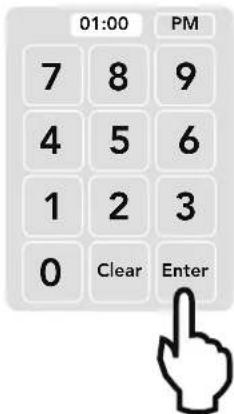
From the RUN DAYS box, touch the desired run day and then touch the START TIME button to display the numeric keypad screen.
Enter the desired time. Toggle the AM/PM button to select your choice. Touch ENTER when finished.
4.3 Set Temperature (For Pool and Spa Only System)
The SET TEMPERATURE allows to preset the pool and spa thermostats. The default pool temperature is 80^ F. The default spa temperature is 102^ F.
Pool and Spa heat temperatures can be adjusted between 34^ F through 104^ F.
NOTE If you enter temperatures outside this range, an invalid entry message will be displayed.
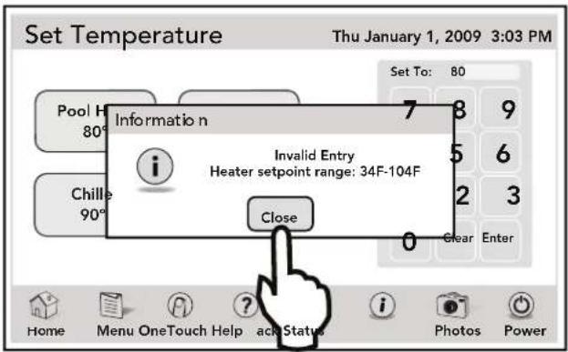
The default TEMP1 temperature is 80^ F. The default TEMP2 is 60^ F.
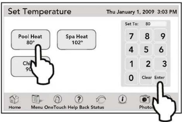
4.3.1 Pool Heat
MENU > SET TEMP > POOL HEAT
From the MENU screen, touch the SET TEMP button to display the SET TEMPERATURE screen.
Touch the POOL HEAT button. Use the numeric keypad to enter the new temperature. Touch ENTER when finished.
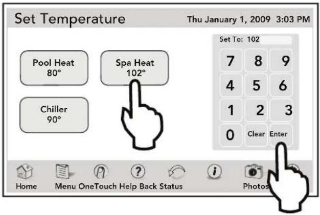
4.3.2 Spa Heat
MENU > SET TEMP > SPA HEAT
From the MENU screen, touch the SET TEMP button to display the SET TEMPERATURE screen.
Touch the SPA HEAT button. Use the numeric keypad to enter the new temperature. Touch ENTER when finished.
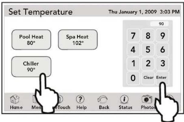
4.3.3 Chiller
NOTE To use this feature, a Jandy AE Heat Pump/Chiller model must be installed. If not installed, the chiller button will not be displayed.
MENU > SET TEMP > CHILLER
From the MENU screen, touch the SET TEMP button to display the SET TEMPERATURE screen.
Touch the CHILLER button. Touch the CLEAR button in the numeric pad to erase existing temperature. Use the numeric keypad to enter the new temperature. Touch ENTER when finished.
4.4 To Set Up Date/Time
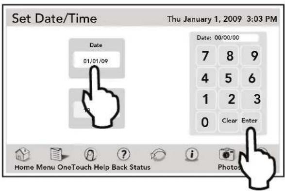
The DATE/TIME screen allows to enter the current date and time. The correct time and date ensures that programming will work properly.
4.4.1 Date
MENU > SET DATE/TIME
From the MENU screen, touch the SET DATE/TIME button to display the SET DATE/TIME screen.
On this screen, touch the DATE button. Enter a date in Month-Day-Year format. Touch ENTER to save the new date.
4.4.2 Time
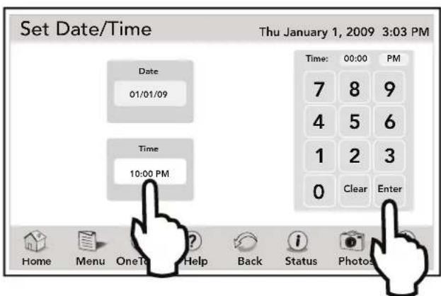
MENU > SET DATE/TIME
From the SET DATE/TIME screen, touch the TIME button. Enter new time. Toggle the AM/PM button to select your choice. Touch ENTER when finished.
4.5 Customize Home
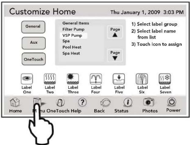
The CUSTOMIZE HOME screen is used to link the icons of the HOME screen to general items, auxiliaries, and OneTouch settings.
MENU > CUSTOMIZE HOME
From the MENU screen, touch the CUSTOMIZE HOME button to display the CUSTOMIZE HOME screen.
4.5.1 Customize General, Aux and OneTouch Items
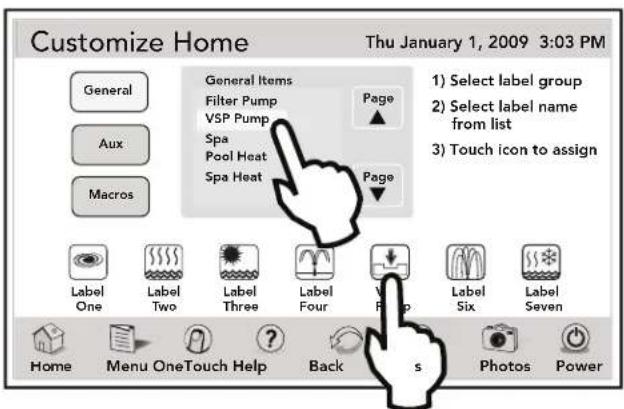
Highlight the GENERAL, AUX or ONETOUCH button. Select the desired item from the item list. Touch an icon from the bottom list. The label of the icon should reflect the assigned item.
Use the UP/DOWN arrows to scroll the list.
4.6 Lockouts Password
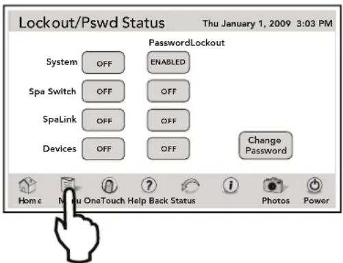
The LOCKOUTS PASSWORD menu prevents changes to specific AquaLink RS operations.
When SYSTEM feature is on "LOCK", changes to program and system setup items are prevented. When SPALINK® RS and SPA SWITCH features are on "LOCK", all control from the SpaLink RS and Spa Side Switch are prevented.
When DEVICE feature is on "LOCK", the selected device cannot be controlled manually. However, the device can be controlled by a program. With LOCKOUT PASSWORD, the user may restrict access to programs, temp settings, group settings, and system setup. One practical use of this feature might be to allow an owner to restrict the control of equipment located at a rental property.
NOTE Password must be four (4) numbers and the same password is used for System, Programs, Spa Side Switch, SpaLink and Devices.
4.6.1 To Lock Out Devices
MENU > LOCKOUTS PASSWORD
From the MENU screen, touch the LOCKOUT button to display the LOCKOUT/PASSWORD screen.
Touch the LOCKOUT or PASSWORD button and choose one of the following options: System, SpaSwitch, SpaLink and Devices.
Toggle the LOCKOUT button on the desired item to turn it ON or OFF.
Toggle the PASSWORD button on the desired item to turn it ON or OFF.
4.6.2 To Set Lockout Password
MENU > LOCKOUTS PASSWORD
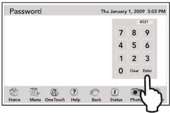
From the MENU screen, touch the LOCKOUTS button to display the LOCKOUTS PASSWORD screen.
Touch the CHANGE PASSWORD button to display the PASSWORD screen. Enter a new password in the numeric keypad. If you make any mistake with your entry, touch the CLEAR button to reset and enter your new password again. Touch ENTER to save your new password.
4.6.3 How to Use the System when a Password is Enabled
If a password is enabled for the system and a user tries to access: Set Temp, Set Time, Programs, Program Groups, or System Setup, a Password Entry Screen will appear to allow the user to continue with their selection.
If a password is enabled for a device, and a user tries to access that device from a OneTouch control panel, a password entry screen will appear to allow the user to continue with their selection.
If a password is enabled and entered for a SpaLink or a Spa Side Remote and a user tries to use either of those devices, the units will not respond.
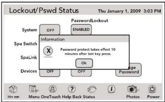
To enable any of these devices, touch the LOCKOUT PASSWORD button in the MENU screen. Choose the equipment and touch the PASSWORD button in the LOCKOUT/PSWD STATUS screen and enter the current password. The system will accept a default password of 1234. The password can be changed.
NOTE Once a password has been entered, you can access the device or menu item. If you do not press any keys for 10 minutes, then you will be required to enter the password when you try to access the device or menu item.
When changing the password be sure to write down this new password and save it someplace where it can be retrieved in the event that it is forgotten. If a password is forgotten, consult your dealer for instructions.
Passwords will only be applied if the PASSWORD PROTECT item is set to ENA and a PASSWORD is entered. Password protecting the system, programs, or devices does not require LOCKOUTS to be set for those devices.
4.7 AquaPure®
NOTE This equipment may not be part of your system. Please check with your installer.
The AquaPure chlorine generator system exclusively communicates with the AquaLink RS.
NOTE When the Chlorine Generator output percentage is set to a value greater than 0 and the filter pump is on, the system salinity level and output percentage appears on the equipment status screen.
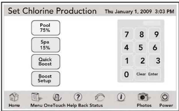
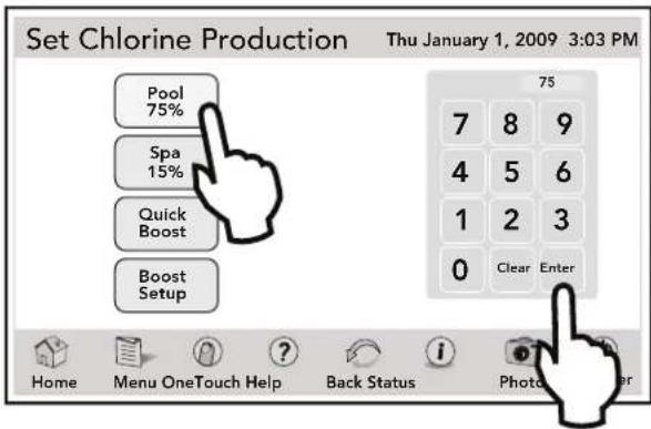
MENU > SET AQUAPURE > SET CHLORINE PRODUCTION
Turn the filter pump on, then from the MENU screen, touch the SET AQUAPURE button to display the SET CHLORINE PRODUCTION screen.
4.7.1 To Set Up Pool/Spa
Touch the POOL or SPA button. Enter new percentage and touch ENTER when finished.
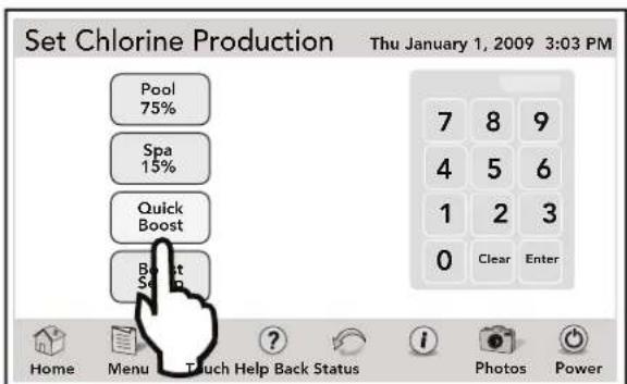
4.7.2 To Set Up Quick Boost
Touch the QUICK BOOST button to display the AQUAPURE BOOST menu.
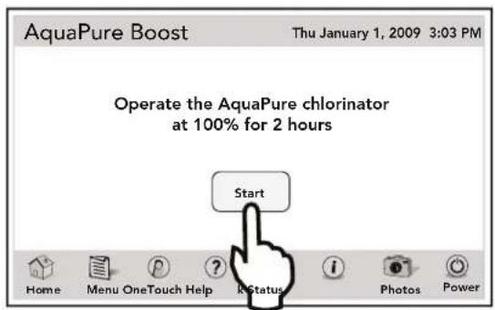
Touch the START button to operate the AquaPure® chlorinator.
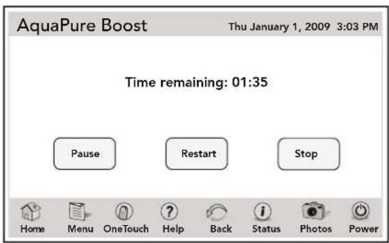
4.7.3 To Pause, Restart and Stop Quick Boost
From the SET CHLORINE PRODUCTION screen, touch the QUICK BOOST button.
- Touch the PAUSE button to pause quick boost operation.
- Touch the RESTART button to restart quick boost operation after being paused.
- Touch the STOP button to stop the operation.
NOTE This screen will appear on the AquaLink Touch controller when the AquaPure chlorinator starts operating.
4.7.4 Boost Setup
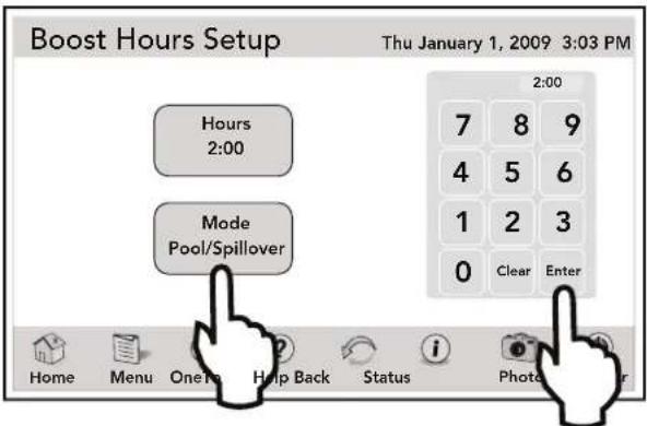
Touch the BOOST SETUP button to display the BOOST HOURS SETUP menu.
Using the numeric keypad, touch the CLEAR button to erase existing hours. Enter new hours. Touch ENTER when finished. If selecting MODE, toggle the MODE button to choose pool or spillover.
4.8 Touch Setup
The TOUCH SETUP screen allows you to set up the display features of the AquaLink Touch controller screen.
MENU > TOUCH SETUP
From the MENU screen, touch the TOUCH SETUP button to display the TOUCH SETUP screen.
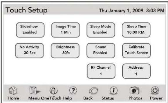
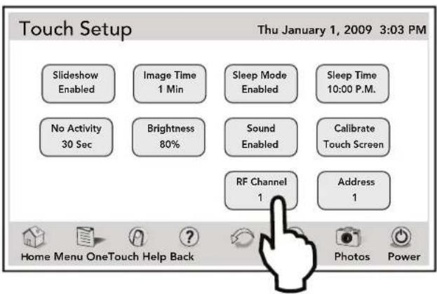
Note that the wireless AquaLink Touch controller displays an additional RF CHANNEL button.
See Section 4.8.5, "RF Channel (For wireless units only)".
The following items shown on this screen: SLIDESHOW, IMAGE TIME, SLEEP MODE, SLEEP TIME, and NO ACTIVITY are explained in the slideshow section of this manual.
See Section 8, "Using the Photos Menu".
4.8.1 Brightness
The AquaLink Touch screen is designed to be lit so that you can use this controller in various lighting conditions. The brightness of the screen can be easily adjusted.
From the TOUCH SETUP screen, touch the BRIGHTNESS button, and the screen will brighten by increments of 10%. The default setting for this feature is 80%.
NOTE After reaching 100% brightness, the screen will darken back to 10%, if the BRIGHTNESS button is touched again.
4.8.2 Sound
The sound is a single tone, generally made when touching the buttons on the AquaLink Touch screen.
- DEFAULT - Enabled.
If you want to disable the sound, touch the SOUND button on the TOUCH SETUP screen.
4.8.3 Calibrate the AquaLink Touch
The AquaLink Touch controller is a touch-sensitive device and must be calibrated when the links are not responding to the touch, or when the touch-sensitive area of the buttons are out of place.
The purpose of this procedure is to teach the touch-sensitive panel to recognize the precise location of the buttons and menus.
To calibrate the AquaLink Touch screen, you will need a stylus pen or similar device for point accuracy. You cannot use your finger to calibrate the AquaLink Touch screen.

CAUTION
To avoid scratching or damaging the LCD screen, DO NOT use metal or hard pointed devices to operate the LCD.
From the TOUCH SETUP screen, touch the CALIBRATE TOUCHSCREEN button. A CONFIRM dialog box will appear, touch the OK button to proceed and the CALIBRATION screen shown below will appear.
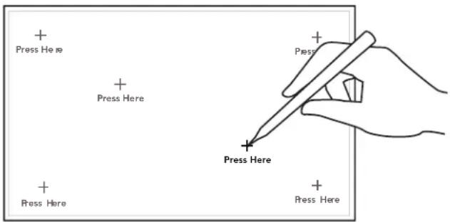
If you are using a stylus pen, make sure to touch the CENTER of the crosshair icons as they appear on the screen.
When calibration is successful, you will hear a loud beep sound, the screen will display a "waiting for connection..." message, and then the HOME screen will appear.
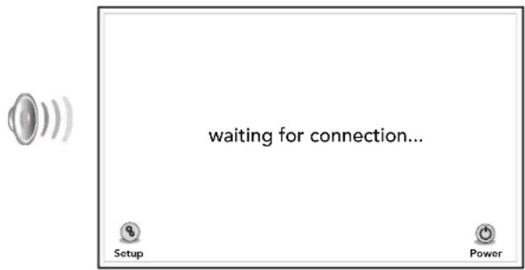
If you fail to calibrate the screen at your first try, simply continue the procedure until calibration succeeds.
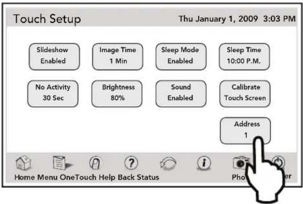
4.8.4 Address
Up to four (4) AquaLink Touch controllers can be connected to a system, but each device must be set to a unique address.
From the TOUCH SETUP screen, toggle the ADDRESS button to change the address.
4.8.5 RF Channel (For wireless units only)
If your AquaLink Touch remote system is turning items on or off at undesignated times, another AquaLink Touch system may be in close proximity using the same or similar frequency channel.
To prevent these unwanted operations, the channel for your AquaLink Touch system can be changed.
The AquaLink Touch handheld remote and the AquaLink Touch transceiver J-Box must be set to the same RF channel.
- At the J-box, remove the cover to expose the PCB.
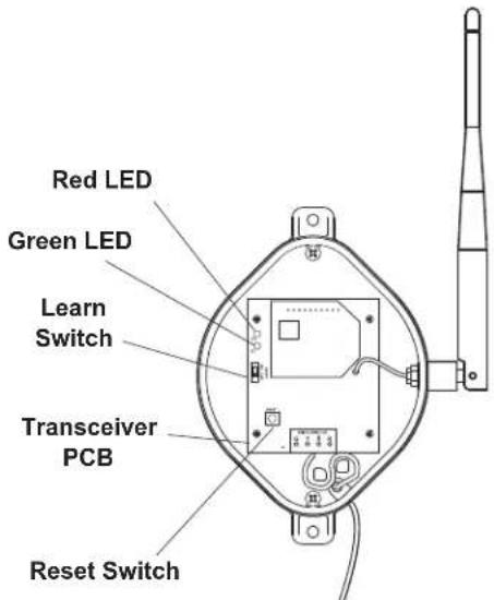
- At the J-box, slide the Learn Switch to ON. If it is not doing so already, the AquaLink Touch screen will display the "waiting for connection..." screen after a maximum of 10 seconds.
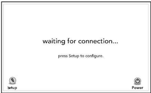
-
From the AquaLink Touch "waiting for connection..." screen, touch the SETUP button. The screen displays "what would you like to set?".
-
Select "RF Channel".
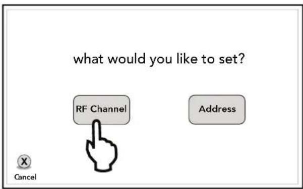
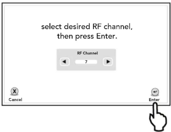
- The AquaLink Touch screen displays "select desired RF channel, then press ENTER. Using the arrow buttons, select the desired channel then touch ENTER.
- The AquaLink Touch screen displays "set LEARN switch in J-Box to ON, then press J-Box RESET."
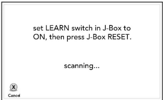
- If it is not already set to ON, set the LEARN switch in J-Box to ON, then press the RESET button in the J-Box.
- At the Transceiver J-Box, the Red and Green LEDs flash alternately while the J-Box searches for the correct channel.
- When the correct channel is found, the J-Box LEDs flash simultaneously and the AquaLink Touch screen displays "channel found! set LEARN switch in J-Box to OFF, then press J-Box RESET".
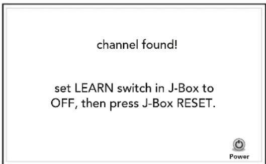
- At the Transceiver J-Box, return the Learn Switch to OFF and press the J-Box RESET switch.
- After a short time, the AquaLink Touch will return to the “waiting for connection…” screen, then to the home screen when connected successfully.
4.8.6 AquaLink Touch J-Box LED Operation
Normal Operating Mode
| Function | LED Indication |
| Reset | Both on continuous for two (2) seconds |
| RS-485 Detected | Both rapid blink simultaneously for two (2) seconds |
| Waiting for AquaLink Touch Beacon | Green LED slow blink |
| RS/AquaLink Touch Communication | Random blink of both LEDS |
Channel Learn Mode
| Function | LED Indication |
| Searching for AquaLink Touch channel | Alternate Red/Green blink |
| AquaLink Touch Channel Learned | Both blink simultaneously |
4.9 Program Group
The PROGRAM GROUP screen allows on and off times for any equipment controlled by the AquaLink RS.
PROGRAM GROUPS are useful for changing between specific settings for summer, winter, or vacation. The AquaLink RS will store on/off times for equipment in each group.
Use the PROGRAM GROUP menu to switch between program group A and program group B. Group A is the default. PROGRAM GROUP A or B will not appear unless PROGRAM GROUP has been selected. Confirm you are in the right program group before programming equipment.
MENU > PROGRAM GROUP
From the MENU screen, touch the PROGRAM GROUP button to display the PROGRAM GROUP screen.
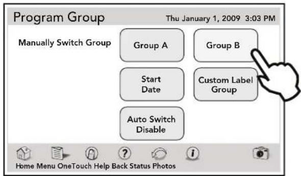
4.9.1 A and B Groups
Highlight the GROUP A or B button to manually switch groups.
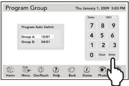
4.9.2 Program Auto Switch
If you like the Program Groups to switch automatically, select a group and enter new date using the numeric keypad. Touch SAVE when finished.
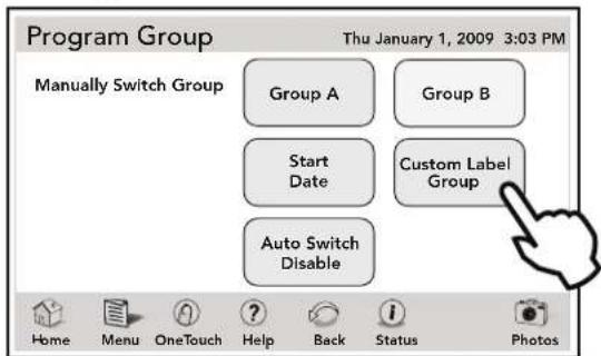
4.9.3 Custom Label Group
The names of the PROGRAM GROUPS can be customized using the CUSTOM LABEL screen.
From the PROGRAM GROUP screen, touch the CUSTOM LABEL GROUP button to display the CUSTOM LABEL screen.
Use this screen to enter your new label as explained in the following section.
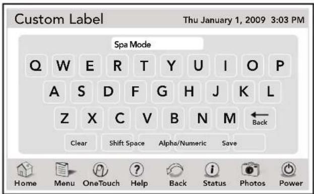
4.9.4 Custom Label
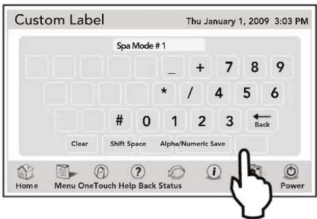
The CUSTOM LABEL screen displays a virtual keyboard and allows users to type data by touching the keys.
The keyboard displays alpha and numeric keys in the standard layout. By touching the ALPHA/NUMERIC key, the screen switches between alpha and numeric keyboard.
A customized label may contain any combination of letters, numbers and special characters. By switching back and forth between the alpha and numeric keyboards, you can enter your customized label combining letters, numbers and special characters.
The maximum number of characters, including empty spaces, allowed in the text field is 16.
4.9.4.1 Using the Alpha Keyboard
Use the alpha keyboard as follows:
- Touch the CLEAR button to erase existing label.
- Enter letters by touching the keys directly.
- Use the SHIFT key to enter letters in upper case.
- Use the SPACE key to space letters or words.
- Touch the BACK key to erase one letter.
- Touch the SAVE key when finished.
4.9.4.2 Using the Numeric Keyboard
From the CUSTOM LABEL screen, touch the ALPHA/NUMERIC button to display the numeric keyboard.
The numeric keyboard, besides the number keys, has extra characters available.
Use the numeric keyboard as follows:
- Touching CLEAR key erases the existing label.
- Enter numbers by touching the keys directly.
- Touching the BACK key erases one number.
- Use the SPACE key to space numbers.
- Touch the SAVE key when finished.
NOTE The SHIFT key has no effect in the numeric keyboard.
Section 5. Using the OneTouch Menu
5.1 OneTouch
Each individual OneTouch mood/scene setting will allow the user to run multiple devices and heat the water to preset temperatures with the touch of one button.
HOME > ONETOUCH
To display the ONETOUCH screen, touch the ONETOUCH button in navigation bar.
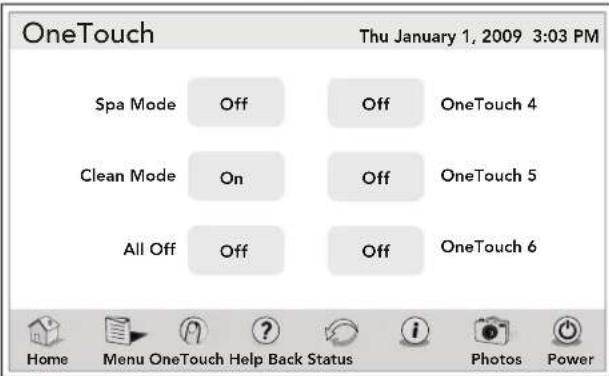
Use this menu to turn on or off any of six (6) mood/scene settings.
If a ONETOUCH button is not assigned to any equipment, touching this button will trigger a warning dialog box with the message "NO DEVICE FOUND".
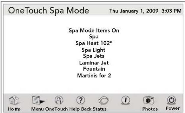
5.2 Spa Mode
HOME > ONETOUCH > SPA MODE
To activate a mood/scene setting of the SPA MODE, touch SPA MODE button on the ONTOUCH screen and the ONTOUCH SPA MODE screen will appear.
5.3 All Off
The ALL OFF mode will turn off equipment that has been turned on by any means (manual or pre-programmed). This includes any of the heaters that were on (unless in use by Maintain function).
Section 6. Using the Help Menu
6.1 Help Menu
The HELP menu displays service information about your local service provider as entered in the PRODUCT INFORMATION system setup section.
See Section 10.17, "Product Information".
The HELP menu screen also provides diagnostic system information such as connection of devices, operation state of sensors, and errors of the system, if any.
MENU > HELP
From the MENU screen, touch the HELP button to display the HELP screen. Touch the PAGE UP or PAGE DOWN button to scroll. The NEXT button will display the HELP SENSORS screen.
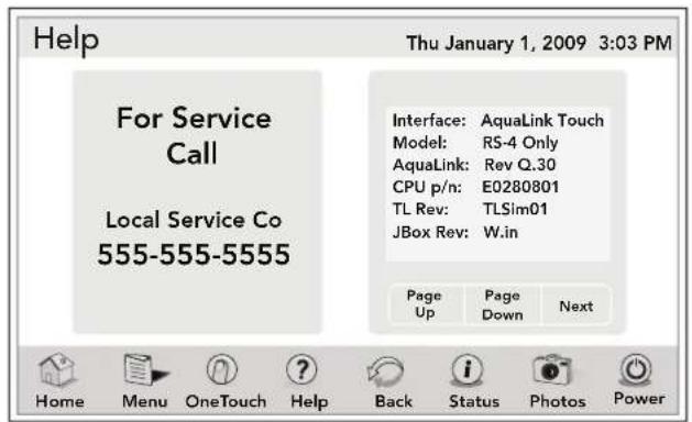
Touch the BACK button to return to the previous screen.
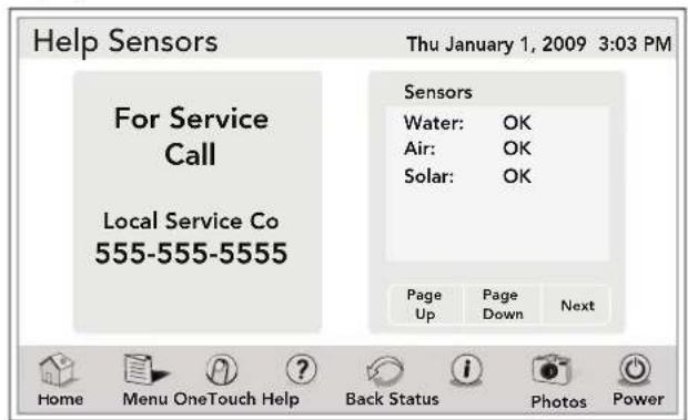
6.2 Help Sensors
This screen displays the operation state of the sensors.
MENU > HELP > HELP SENSORS
From the HELP menu, touch the NEXT button to display the HELP SENSORS screen.
6.3 Help Remotes
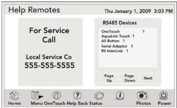
This screen lists all the equipment available through the RS485 Network.
MENU > HELP > HELP REMOTES
From the HELP menu, touch the NEXT button to display the HELP REMOTES screen.
6.4 Help Errors
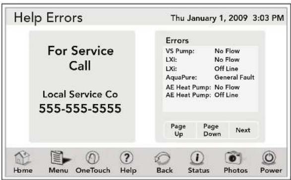
The ERRORS screen lists all equipment with possible faults.
MENU > HELP > ERRORS
From the HELP menu, touch the NEXT button to display the HELP ERRORS screen.
Section 7. Using the Status Menu
7.1 Status Menu
The EQUIPMENT STATUS menu lists the current status of all equipment.
HOME > STATUS
From the HOME screen, touch the STATUS button to display the EQUIPMENT STATUS screen.
Use the UP or DOWN arrows to display additional equipment.
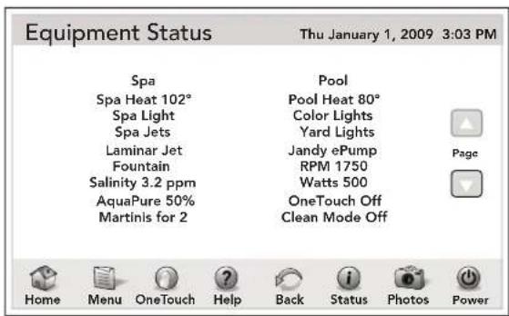
Touch the BACK button to return to the HOME screen.
NOTE The EQUIPMENT STATUS screen will timeout after approximately 25 seconds at which time the previous screen will be displayed.
Section 8. Using the Photos Menu
8.1 Creating a Slideshow
The AquaLink Touch controller brings your digital photos to life and lets you share your favorite memories as a slideshow when the controller is inactive.
Images and slideshows may be displayed from either the memory card or from the AquaLink Touch's internal memory.
NOTE A noticeable processing delay may occur when attempting to save and display larger image files. To minimize these delays, reduce the image size by selecting a lower resolution on the camera or by using an image editing program. For best results, an image file size of 2 megabytes or smaller is recommended.
The AquaLink Touch case housing has a slot where you insert the memory card and then import the photos you wish to use in your slideshow. The AquaLink Touch internal memory has 256 MB of storage (up to 200 images).
NOTE Memory cards supported include memory stick (MS), multimedia cards (MMC), secure digital (SD), and XD picture cards (XD).
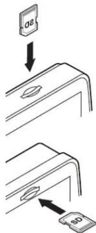
8.2 Inserting a memory card
The slot is designed so a card can only be inserted in the correct direction.

CAUTION
If a memory card is inserted incorrectly, you may damage the memory card or the slot of the AquaLink Touch case.
For wall surface-mount controller and wireless controller push the memory card vertically into the slot as shown below.
On the wall flush-mount controller push the memory card into the slot as shown below.
8.3 Importing and Deleting Digital Photos
HOME > PHOTOS > CHOOSE IMAGE
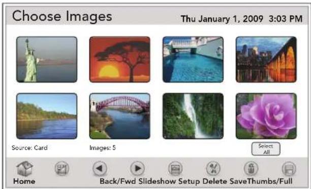
From the HOME screen, touch the PHOTOS button to display the CHOOSE IMAGES screen.
This screen displays the digital photos loaded into the AquaLink Touch memory, but if a memory card has been inserted into the AquaLink Touch case then the photos from the memory card will be displayed.
At the bottom of the screen, the following information is shown:
- SOURCE - AquaLink Touch or memory card
- IMAGES - displays the number of photos
- SELECT/CLEAR ALL - selects/clears all photos
From the CHOOSE IMAGES screen, touch the photos you wish to use. The selected photos will be highlighted. Touch the SAVE button to save the selected pictures to the AquaLink Touch memory.
Use THUMBS/FULL to display photos as thumbs or screen size. Use the BACK/FWD arrows from the navigation bar to scroll to the next set of pictures. Use the DELETE button to remove pictures from the AquaLink Touch memory while in Thumbs view.
8.4 Slideshow Setup
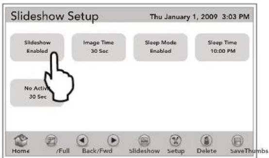
The SLIDESHOW SETUP screen allows you to enable and time the slideshow as desired.
8.4.1 To Enable Slideshow
The SLIDESHOW button is used to enable or disable the slideshow. When ENABLED, the slideshow will be displayed continuously as set by the SLEEP MODE or by the NO ACTIVITY mode.
- DEFAULT - Disable
HOME > PHOTOS > SETUP > SLIDESHOW ENABLED/ DISABLED
From the CHOOSE IMAGE screen, touch the SETUP button to display the SLIDESHOW SETUP screen. Touch the SLIDESHOW to enable the slideshow.
8.4.2 Image Time
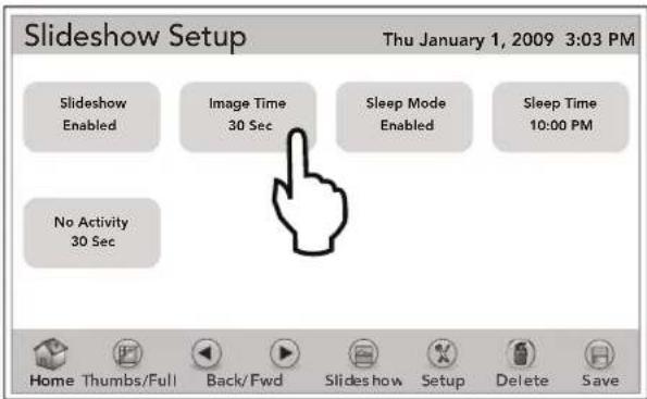
The IMAGE TIME sets the duration time to display each photo when the slideshow is running. This interval may be set from five (5) seconds up to three (3) minutes.
HOME > PHOTOS > SETUP > IMAGE TIME
From the SLIDESHOW SETUP screen, toggle the IMAGE TIME button; the set time will switch from five (5) seconds to 10 seconds, 30 seconds, one (1) minute, and three (3) minutes. Select your choice and the slideshow will show each picture for the length of the designated time.
8.4.3 Sleep Mode and Sleep Time
When enabled, the SLEEP MODE will turn off the screen as set in SLEEP TIME.
PHOTOS > SETUP > SLEEP MODE
From the SLIDESHOW SETUP screen, toggle the SLEEP MODE to enable or disable this feature.
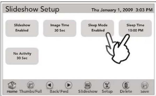
The SLEEP TIME sets the time to turn off the screen when the SLEEP MODE is enabled.
PHOTOS > SETUP > SET TIME
From the SLIDESHOW SETUP screen, touch the SLEEP TIME to display SLIDESHOW OFF TIME screen.
Touch the CLEAR button to erase any existing time. Use the numeric keyboard to set a new time. Toggle the AM/PM button and select your choice. Touch ENTER when finished.
8.4.4 No Activity
The NO ACTIVITY feature will turn off the screen when no activity is detected, after the time set by this control has elapsed.
The NO ACTIVITY time-out can be set 30 seconds, one (1) minute, three (3) minutes, five (5) minutes, or OFF.
The OFF option will keep the screen ON indefinitely. If the SLIDESHOW is enabled and the SLEEP MODE is disabled, the slideshow will run until the screen is touched again.
PHOTOS > SETUP > NO ACTIVITY
From the SLIDESHOW SETUP screen, toggle the NO ACTIVITY button and select your choice.
Section 9. Using Other Devices ON/OFF
9.1 Using Other Devices On/Off
Use this menu to turn on or off manually any equipment. The ALL OFF button is used to turn off equipment that has been turned on by any means (manual or pre-programmed).
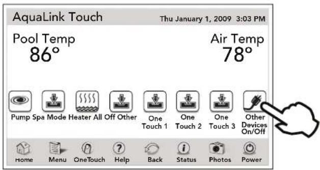
HOME > OTHER DEVICES ON/OFF
From HOME menu, touch the OTHER DEVICES ON/OFF button to display the DEVICES screen. Touch the UP/DOWN arrows to scroll to the next page.
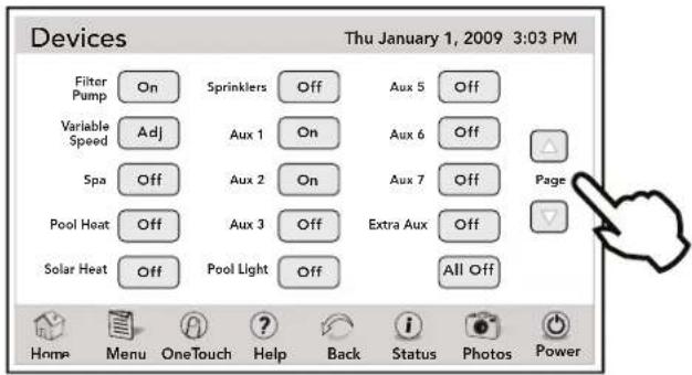
Touch the BACK button in the navigation bar to return to the HOME screen.
9.2 Filter Pump
The FILTER PUMP selection turns the main filtration pump on or off for circulation to the pool. The filter pump also activates if the spa is turned on, if the pool cleaner is turned on, or if the spa spill-over effect is activated.
The main filtration pump circulates the pool or spa water through the filter and heater. The pump must be on if you want to display the pool temperature, or if you want to heat the pool.
HOME > OTHER DEVICES ON / OFF > FILTER PUMP
From HOME menu, touch the OTHER DEVICES ON/OFF button to display the DEVICES screen. Touch the FILTER PUMP button to turn the main filtration pump ON or OFF.
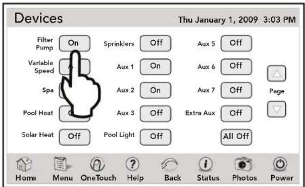
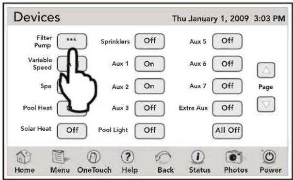
Touch the BACK button in the navigation bar to return to the HOME screen.
9.3 Spa
The SPA mode switches water circulation from the pool to spa (pool/spa combination models only). Turning on the spa also activates the filter pump (after a delay for valve rotation) and deactivates the pool cleaner if it is on.
The SPA mode must be on to display the spa temperature and/or to heat the spa. Activation takes place after a 30 seconds delay (while valves are turning).
HOME > OTHER DEVICES ON / OFF > SPA
In HOME menu, touch the OTHER DEVICES ON/OFF button to display the DEVICES screen. Touch the SPA button to turn the spa ON or OFF.
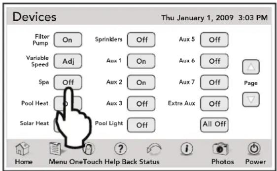
Touch the BACK button in the navigation bar to return to the HOME screen.
9.4 Pool Heat
The POOL HEAT selection enables the heater for the pool. It uses the setting from SET TEMP menu, or you can increase/decrease when enabling.
See Section 4.3.1, "Pool Heat".
HOME > OTHER DEVICES ON / OFF > POOL HEAT
From the HOME menu screen, touch the OTHER DEVICES ON/OFF button to display the DEVICES screen. Touch the POOL HEAT button to ENABLE the pool heat.
Touch the BACK button in the navigation bar to return to the HOME screen.
9.5 Spa Heat (Dual Equipment)
The SPA HEAT enables the heater for the spa. It uses the settings from SET TEMP menu, or you can increase/decrease when enabling.
See Section 4.3.2, "Spa Heat".
HOME > OTHER DEVICES ON / OFF > SPA HEAT
From the HOME menu screen, touch the OTHER DEVICES ON/OFF button to display the DEVICES screen. Touch the SPA HEAT button to ENABLE the spa heat.
Touch the BACK button in the navigation bar to return to the HOME screen.
9.6 Solar Heat
The SOLAR HEAT selection controls solar heating. A solar heating system and optional solar sensor are required for SOLAR HEAT selection to operate.
HOME > OTHER DEVICES ON / OFF > SOLAR HEAT
From the HOME menu screen, touch the OTHER DEVICES ON/OFF button to display the DEVICES screen. Touch the SOLAR HEAT button to turn solar heat ENA or OFF.
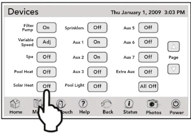
Touch the BACK button in the navigation bar to return to the HOME screen.
NOTE If a Heat Pump is properly connected to this system, HEAT PUMP will appear on the screen in place of SOLAR HEAT.
NOTE If a solar sensor is not installed, EXTRA AUX replaces SOLAR HEAT and may be used to control an auxiliary piece of equipment (see the following Section 9.7, "Auxiliary Equipment" to turn on or off EXTRA AUX).
For solar heating to take place, the SOLAR HEAT (in DEVICES ON/OFF) must be enabled, and also the filter pump must be on. Solar temperature must be at least 5°F above the water temperature and the water must be cooler than the thermostat setting.
9.7 Auxiliary Equipment
The AUX modes control each of the auxiliary devices. To assign a different name to an auxiliary device, use the SYSTEM SETUP and LABEL AUX screen.
HOME > DEVICES > AUX3
From the HOME menu screen, touch the OTHER DEVICES ON/OFF button to display the DEVICES screen.
From the DEVICES screen, toggle the AUX3 button to turn the auxiliary device ON or OFF.
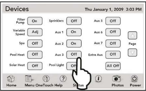
Touch the BACK button in the navigation bar to return to the HOME screen.
9.8 Using Color Lights
NOTE This equipment may not be part of your system. Please check with your installer.
The SET COLOR menu is used to set the color of a color light and then turn the light on.
NOTE Prior to setting the color of the light, the light must be assigned and controlled by an auxiliary (for example, AUX 1). Please note that the auxiliary control can be custom labeled.
HOME > OTHER DEVICES ON/OFF > AUX1 > SET COLORS
From the HOME screen, touch the OTHER DEVICES ON/OFF button to display the DEVICES screen.
Touch the auxiliary assigned to the color light on the DEVICES screen to display the SET COLORS screen and touch the desired color light.
IMPORTANT Information
Do not activate this feature unless you are certain that color lights are installed on your system
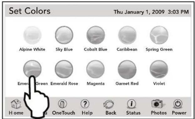
If you select POOL LIGHT or SPA LIGHT from the EQUIPMENT ON/OFF menu and the light is already ON, touching the color light on the SET COLOR screen will display a confirmation message "LIGHT WILL TURN OFF IN 5 SECONDS. IF YOU WANT TO CHANGE THE COLORS PRESS OK NOW".
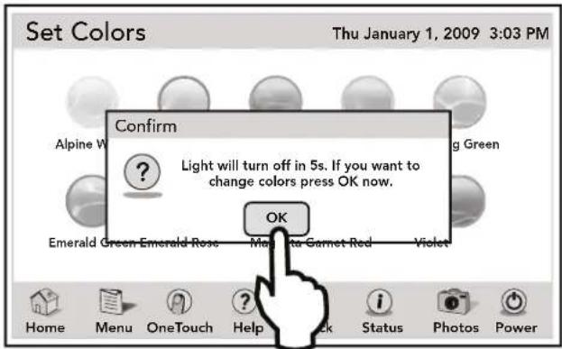
If you touch the OK button, the SET COLOR screen will be displayed and will allow you to select a different color. If a different color is chosen, the light will reset to Alpine White, rotate to the selected color, and then automatically lock on to that color.
During the color rotation, the message "PLEASE WAIT...CYCLING TO CHOSEN COLOR" will be displayed.
NOTE When a pool or spa light is turned ON manually, by the OneTouch control panel, or by a program, the last used color will automatically be chosen unless you press SELECT to change the color.
If you press the BACK key when in the EQUIPMENT ON/OFF menu, the light will turn on the last selected color. If the SELECT key or the BACK key is not pressed, and if it has been 15 seconds since the UP/DOWN keys have been pressed, then the most recently selected color will be selected again.
9.9 TEMP1 / TEMP2 (Pool or Spa Only)
TEMP1 is the priority temperature. It must be set higher than TEMP2, and it overrides TEMP2 whenever it is enabled. Set temperature for TEMP1 before setting temperature for TEMP2.
9.9.1 To Set Up TEMP1
NOTE The valid temperature setpoint range is between 34^ - 104^ F. If you enter a value outside this range, an invalid entry message will appear on screen.
HOME > OTHER DEVICES ON / OFF > DEVICES > TEMP1
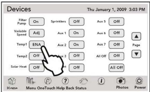
From the HOME menu screen, touch the OTHER DEVICES ON/OFF button to display the DEVICES screen.
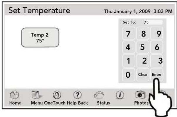
From the DEVICES screen, touch the TEMP1 button to display the SET TEMPERATURE.
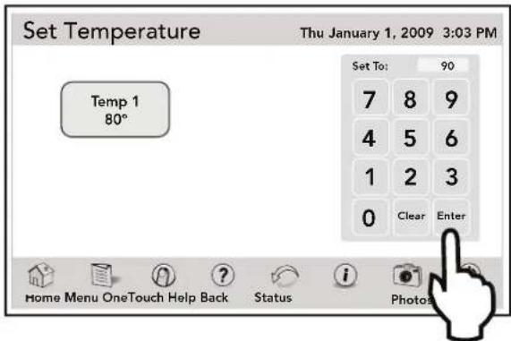
Set the desired temperature on the numeric keypad as follows:
- Enter the desired water temperature.
- Touch ENTER when finished to make new temperature to take effect.
9.9.2 To Set Up TEMP2 (For Pool and Spa Only System)
The TEMP2 is the maintenance (low) temperature. It must be set lower than TEMP1. If TEMP2 is on and TEMP1 is activated, TEMP2 will turn off. When TEMP1 is turn off again, TEMP2 will reactivate.
NOTE The valid temperature setpoint range is between 34^ - 104^ F. If you enter a value outside this range, an invalid entry message will appear on screen.
HOME > OTHER DEVICES ON / OFF > DEVICES > TEMP2
From the HOME menu screen, touch the OTHER DEVICES ON/OFF button to display the DEVICES screen. From the DEVICES screen, touch the TEMP2 button to display the SET TEMPERATURE screen.
Set the desired temperature on the numeric keypad as follows:
- Enter the desired water temperature.
- Touch ENTER when finished to make new temperature to take effect.
9.10 Two Speed Operation (\*Not Available for Export Models\*)
NOTE This equipment may not be part of your system. Please check with your installer.
- Optional TWO SPEED RELAY required.
9.10.1 Two Speed Manual Operation
- For Pool and Spa Combination Units
If your control is a Pool and Spa combination with a 2-speed fi ltration pump, the control will operate as follows: High Speed (Filter Pump) must be on before Low Speed. Filter pump button, as well as the Spa button, turns it to High Speed. Low Speed (AUX 2) button toggles back and forth from low to high.
- For Pool or Spa Only Units
To use HIGH/LOW Speeds, Filter Pump turns on HIGH SPEED, AUX 2 turns on LOW SPEED. Whatever mode last used is the OFF button. To toggle, touch whichever speed is not on.
• For Dual Equipment Units
AquaLink RS 2/6 operates the same as the Pool/Spa Only units; i.e., Filter Pump turns on HIGH SPEED and AUX 2 turns on LOW SPEED. The mode last used is the OFF button. To toggle, touch whichever speed is not on. 2-speed works only on spa fi lter pump.
- Two Speed Programming for All Units
When programming HIGH and LOW Speeds to operate together, think of HIGH SPEED (Filter Pump) as total duration of fi ltration time, then set Low Speed (AUX 2) to operate within that duration. For example, if you want High Speed on for 2 hours and Low Speed for 10 hours, program the Filter Pump (High Speed) from 8 AM to 8 PM and Low Speed from 10 AM to 8 PM.
NOTE It is not necessary to program both HIGH and LOW Speeds, even with a combo control system. If only LOW SPEED is programmed, HIGH SPEED will turn on at the LOW SPEED on time to prime the pump. After three (3) minutes the system will switch to LOW SPEED for the remainder of its programmed time.
9.10.2 High Speed Filtration Pump
HOME > OTHER DEVICES ON / OFF > FILTER PUMP/ SPA
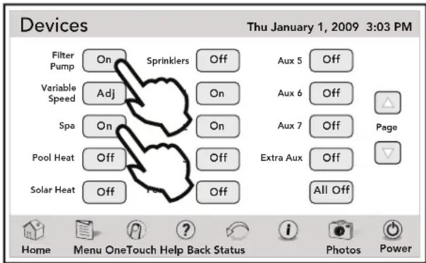
From HOME menu, touch the OTHER DEVICES ON/OFF button to display the DEVICES screen. Touch the FILTER PUMP or SPA button to turn the main filtration pump ON to HIGH SPEED.
9.10.3 Low Speed Filtration Pump
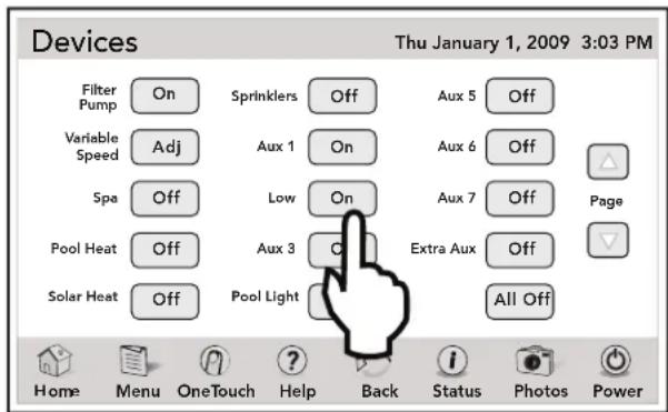
HOME > OTHER DEVICES ON / OFF > AUX 2
From HOME menu, touch the OTHER DEVICES ON/OFF button to display the DEVICES screen. Touch the FILTER PUMP button to turn the main filtration pump ON to LOW SPEED.
Section 10. System Setup
10.1 System Setup Screen
The SYSTEM SETUP menu screen allows you to configure pool/spa equipment, devices and AquaLink Touch features. This section of the manual provides instructions to set up most of these equipment.
For the following equipment, see their corresponding section.
See Section 2, "Overview of the AquaLink Touch Controller".
See Section 11, "Heat Pump Setup".
See Section 12, "Variable Speed Pump Setup".
See Section 14, "ChemLink™ Setup".
NOTE Some equipment may not be part of your system. Please check with your installer.
10.1.1 To Access System Setup
MENU > SYSTEM SETUP
From the MENU screen, touch the SYSTEM SETUP button to display the SYSTEM SETUP menu.
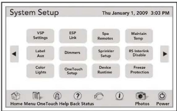
Use the ARROW buttons to display additional equipment.
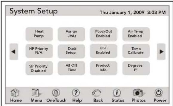
Use the ARROW buttons to display additional equipment.
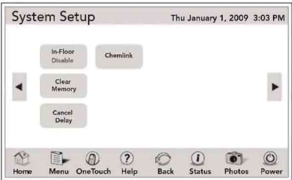
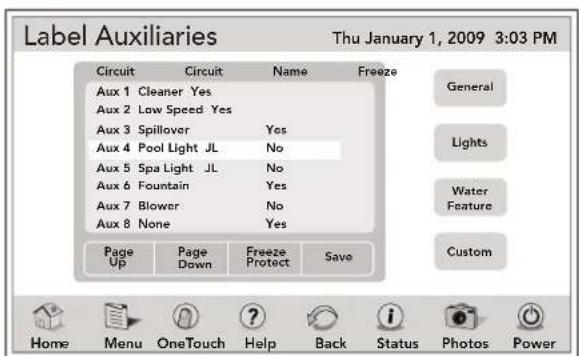
10.2 Label Auxiliary Functions
The LABEL AUX menu allows custom naming of auxiliary equipment. For example, you can set the display to read Pool Light JL instead of AUX 4.
10.2.1 To Set Up Label Auxiliary
MENU > SYSTEM SETUP > LABEL AUX
From the SYSTEM SETUP screen, touch the LABEL AUX button to display the LABEL AUXILIARIES screen.
Highlight the CIRCUIT and touch your choice - general, lights, water features, or custom.
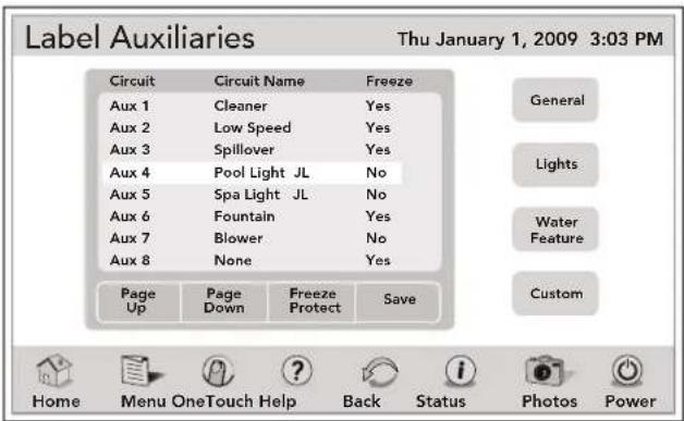
NOTE Please be aware that if the label NOT USED from the GENERAL LABEL menu is used on an AUX relay, the relay will not engage.
10.3 Color Lights
NOTE This equipment may not be part of your system. Please check with your installer.
The COLOR LIGHTS screen is used to select the color light type (Jandy Colors, Jandy LED Light, SAm ^TM /SAL ^® , or Color Logic ^® ), and to assign the color light to an available auxiliary relay.
10.3.1 To Set Up Color Lights
MENU > SYSTEM SETUP > COLOR LIGHTS
From the SYSTEM SETUP screen, touch COLOR LIGHTS screen to display the COLOR LIGHT SETUP screen. This screen shows four choices: Jandy LED Light, Jandy Colors, Hayward® Color Logic, and Pentair® SAm/SAL.
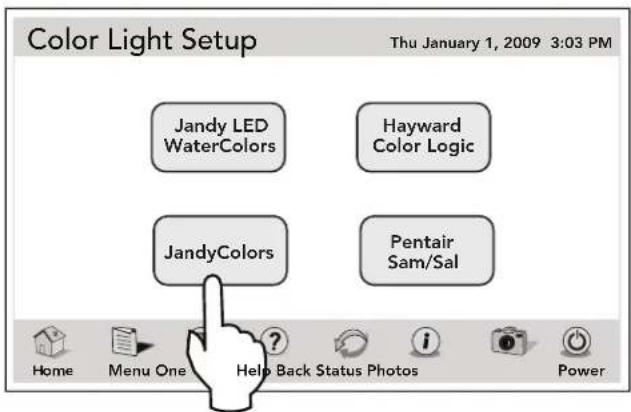
Touch your choice of color light type to display the COLOR LIGHT ASSIGN AUX screen. This screen shows a list of available auxiliaries.
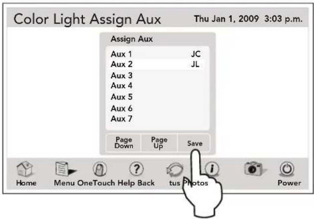
Touch an auxiliary to be assigned to a color light. "JC" will appear next to the AUX if a Jandy Colors has been assigned. "JL" will appear next to the AUX if a Jandy LED Light has been assigned. "SL" will appear next to the AUX if a SAm/SAL Light has been assigned. "CL" will appear next to the AUX if a Color Logic Light has been assigned.
If the AUX is touched again, while on the same selected item, the "JC", "JL", "SL", or "CL" will disappear meaning that a color light is no longer being controlled by the auxiliary.
Use the PAGE UP/PAGE DOWN button to view additional auxiliaries. Touch the SAVE button when finished.
10.4 ESP Link (Seasonal Adjust)
The SEASONAL ADJUST menu is a feature that will automatically adjust filtration cycles, chlorine levels, water leveling, and sprinkler times based on the seasons, when outdoor temperatures typically change.
NOTE The table below shows the various default seasonal adjust values and their respective adjustable range.
| DEFAULT ADJUST VALUE | ADJUSTABLE RANGE | |
| FILTRATION 1 hour 0.5 hr, 1 hr, | 1.5 hrs, 2 hrs | |
| CLEANER 1 hour 0.5 hr, 1 hr, | 1.5 hrs, 2 hrs | |
| AQUAPURE® | 15% | 10%, 20% |
| SPRINKLERS | 5 minutes | 1 - 10 minutes |
| FILL LINE | 5 minutes | not adjustable |
10.4.1 To Set Up Seasonal Adjust
MENU > SYSTEM SETUP > ESP LINK > SEASONAL ADJ
From the SYSTEM SETUP screen, touch the ESP LINK button to display the ESP LINK screen.
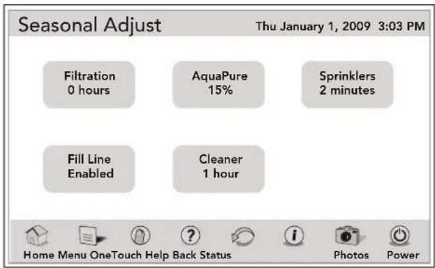
Touch the appropriate button to choose FILTRATION, SPRINKLERS, FILL LINE, and CLEANER.
10.4.2 ESP Link Operation
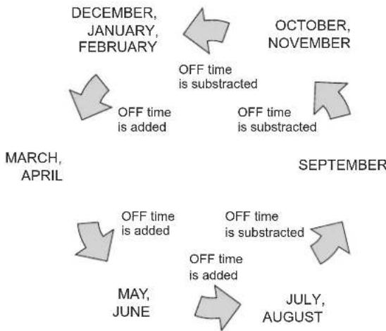
The following example shows how the feature operates when the FILTRATION ADJUSTMENT value has been set to one (1) hour.
In our example we will assume that a program for the FILTER PUMP is entered in the month of March, with the program parameter shown.
- When the month changes from April to May, one (1) hour is added to the OFF time.
- When the month changes from June to July, another one (1) hour is added to the OFF time.
- When the month changes from August to September, one (1) hour is subtracted from the OFF time.
- When the month changes from September to October, another one (1) hour is subtracted from the OFF time.
- When the month changes from November to December, another one (1) hour is subtracted from the OFF time.
- When the month changes from February to March, one (1) hour is added to the OFF time and we are back where we started.
flowchart
graph TD
    A["DECEMBER, JANUARY, FEBRUARY"] --> B["OFF time is added"]
    B --> C["OCTOBER, NOVEMBER"]
    C --> D["OFF time is subtracted"]
    D --> E["MARCH, APRIL"]
    E --> F["OFF time is added"]
    F --> G["SEPTEMBER"]
    G --> H["OFF time is subtracted"]
    H --> I["MAY, JUNE"]
    I --> J["JULY, AUGUST"]
This chart shows when the seasonal adjust offset is added or subtracted from the programmed OFF time.
10.5 Set Dimmers
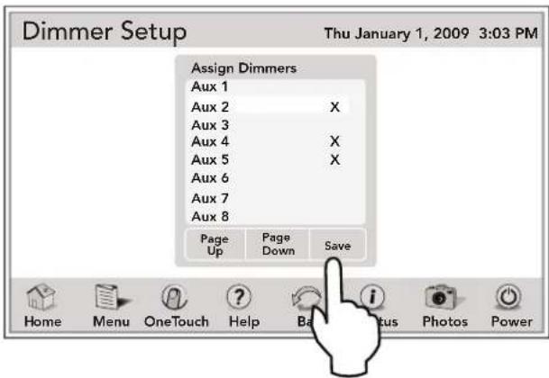
This menu is used to assign an auxiliary to control a dimmable light. A light dimming relay must be installed in order for your light(s) to be dimmable.
NOTE An optional Light Dimming Relay must be installed and only 120 VAC lighting (or suitable transformer-driven lights) can be dimmed.
10.5.1 To Set Dimmers
MENU > SYSTEM SETUP > DIMMERS
From the SYSTEM SETUP screen, touch the DIMMERS button to display the DIMMERS setup screen. In the ASSIGN DIMMERS box, touch the auxiliary to be dimmable. An "X" will appear next to selected item. Use the PAGE DOWN/PAGE UP to view additional items. Touch SAVE when finished.
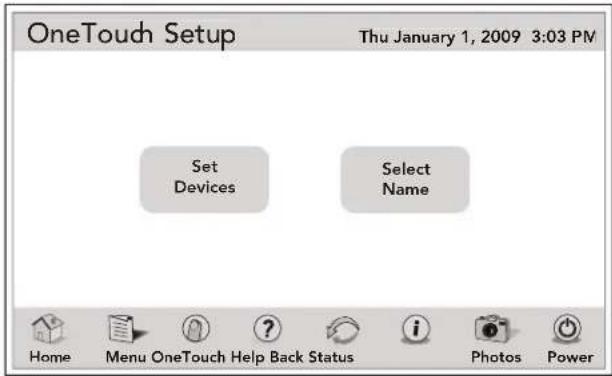
10.6 OneTouch
This screen allows custom configuration of the six (6) OneTouch mood/scene buttons. Each mood setting allows for an independent thermostat setting. OneTouch setting can also be assigned to any SpaLink® button.
MENU > SYSTEM SETUP > ONETOUCH SETUP
Touch the ONETOUCH button on the SYSTEM SETUP menu to display the ONETOUCH SETUP screen.
10.6.1 Select Devices
Touch the SELECT DEVICES button on the ONETOUCH SETUP menu to display menu shown below. Touch any of the six (6) ONETOUCH buttons to be assigned. In the ASSIGN DEVICES list choose a selection and touch the SAVE button when finished.
Repeat this procedure to assign devices to the rest of ONETOUCH buttons.
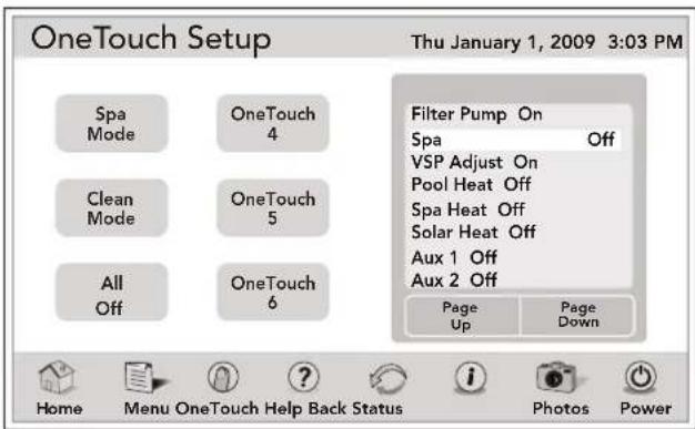
Touch the BACK button to return to ONETOUCH SETUP menu.
10.6.2 Select Name
Touch the SELECT NAME button on the ONETOUCH SETUP menu to display the ONETOUCH SETUP menu.
Touch the CUSTOM LABEL button to display the CUSTOM LABEL menu.
See Section 4.9.4, "Custom Label".
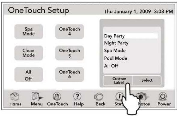
Repeat this procedure to assign custom labels to the rest of ONETOUCH buttons.
Touch the BACK button to return to ONETOUCH SETUP menu.
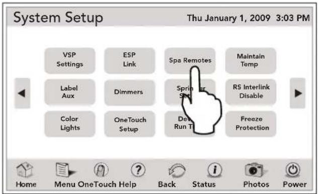
10.7 Spa Remotes
The SPA REMOTES SETUP is used to set up the 4-Function Spa Switch or the 8-Function SpaLink.
MENU > SYSTEM SETUP > SPA REMOTES
From the SYSTEM SETUP screen, touch the SPA REMOTES button to display the SPA REMOTES SETUP screen.
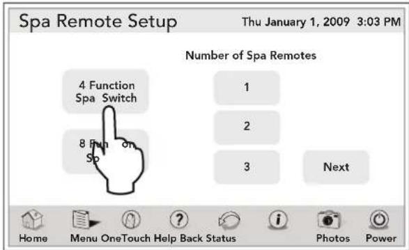
10.7.1 Spa Side Switch
The 4 Function Spa Switches are spa, spa heat, aux1 and aux2. Write down the spa side switch button assignments to label the buttons on the switch with the label pack provided.
MENU > SYSTEM SETUP > SPA REMOTES
From the SPA REMOTES SETUP screen, touch the 4 FUNCTION SPA SWITCH button and the number of spa remotes you have and then touch the NEXT button to display the SPA REMOTES SETUP screen.
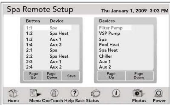
As shown in the following screen, the SPA REMOTES SETUP screen contains the BUTTON/DEVICE and DEVICES lists.
Highlight the selected button in the BUTTON/DEVICE list, then highlight the equipment in the DEVICES LIST. Touch the SAVE button to save this setting.
Use the PAGE UP/PAGE DOWN button to view additional items.
10.7.2 SpaLink® Setup
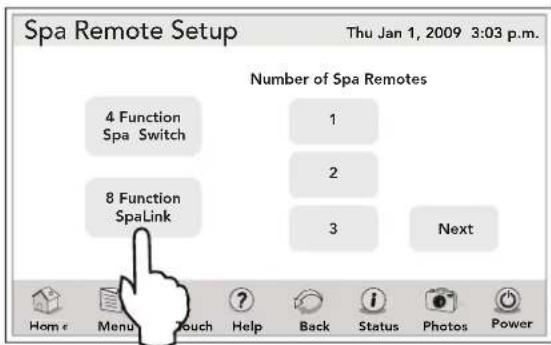
The 8 Function SpaLink are spa, spa heat, aux1, aux2, aux3, aux4, aux5, and aux6.
You can now assign a OneTouch macro setting to any button on the SpaLink remote. Write down your SpaLink button assignments so that you can label the buttons on the switch with the label pack provided.
MENU > SYSTEM SETUP > SPA REMOTES
From the SPA REMOTES SETUP screen, touch the 8 FUNCTION SPA SWITCH button and the number of spa remotes you have and then touch the NEXT button to display the SPA REMOTES SETUP screen.
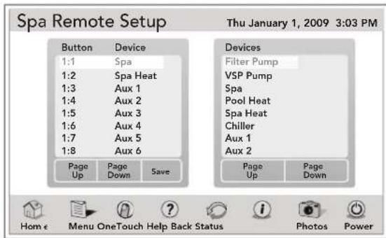
As shown in the following screen, the SPA REMOTES SETUP screen contains the BUTTON/DEVICE and DEVICES lists.
Highlight the selected button in the BUTTON/DEVICE list, then highlight the equipment in the DEVICEs LIST. Touch the SAVE button to save this setting.
Use the PAGE UP/PAGE DOWN button to view additional items.
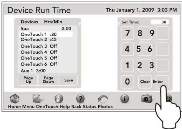
10.8 Device Runtime
The DEVICE RUNTIME menu is used to assign a runtime for a device or auxiliary.
When the device is turned on from the OTHER EQUIPMENT ON/OFF menu, it will run for the duration specified on the DEVICE RUNTIME menu.
NOTE A device runtime can be assigned to SPA, AUX1 - AUX31, EXTRA AUX, and macros ONETOUCH1 - ONETOUCH6 from a minimum of 1 minute to a maximum of 5 hours.
The default runtime of 30 minutes will be displayed.
10.8.1 To Set Up Device Runtime
MENU > SYSTEM SETUP > DEVICE RUNTIME
From the SYSTEM SETUP screen, touch the DEVICE RUNTIME button to display the DEVICE RUNTIME screen. On this screen, touch the device of your choice. Enter your new time using the numeric keypad and touch the ENTER button when finished.
Use the PAGE DOWN/PAGE UP button to view additional devices. Touch the SAVE button to save the updated settings and to exit this screen.
10.9 Maintain Temp
NOTE Maintain Temp is designed to operate outside (before or after) the normal filtration pump times.
The MAINTAIN TEMP menu provides the ability to specify how often the filter pump is turned on to sample the water temperature. This feature allows for the sampling interval to be set to one (1), two (2), or four (4) hours. The default value will be two (2) hours.
10.9.1 To Set Up Maintain Temp
Note that the MAINTAIN TEMP will run the pump for the chosen body of water to keep the water at the desired temperature, is this function is ON and the heater/chiller (if installed) is enabled. The system will automatically turn on the pump every couple of hours for just enough time to test the water temperature. If the temperature meets the set point, the pump will return to off. If the measured temperature is different than the set temperature, the pump will stay on and the heater/chiller will operate long enough to bring the water to the set temperature.
MENU > SYSTEM SETUP > MAINTAIN TEMP
From the SET TEMPERATURE screen, touch the MAINTAIN TEMP button to display the MAINTAIN TEMP screen.

Schedule the MAINTAIN TEMP as follows:
- On the MAINTAIN TEMP screen, touch the START time of the selected equipment, and use the numeric keypad to enter the new time.
- If you make a mistake, touch the CLEAR button and re-enter new time again. Touch the ENTER button when finished.
- To set the stop time, touch the STOP time of the selected equipment and use the numeric keypad to enter the new time.
- To set the sample time, touch the SAMPLE time of the selected equipment and use the numeric pad to enter the new sampling interval.
- Touch the ON/OFF button to enable or disable the MAINTAIN TEMP schedule of the selected equipment.
- Touch SAVE when finished.
10.10 RS InterLink
NOTE This equipment may not be part of your system. Please check with your installer.
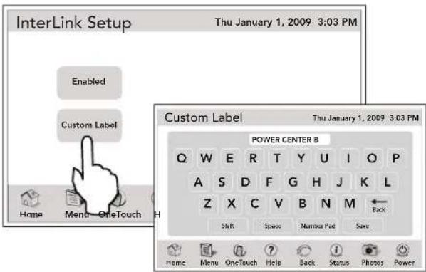
The RS InterLink menu allows a single controller to access two main power centers on the AquaLink RS system.
For case of operation, it is suggested that each power center be given a custom product name that would allow a user to identify to which power center the controller is connected. During operation, this name will appear on the AquaLink Touch Date/Time screen.
NOTE The RS InterLink feature must be enabled before it may be accessed from the OTHER EQUIPMENT ON/OFF screen.
10.10.1 To Set Up RS Intelink
MENU > SYSTEM SETUP > RS INTERLINK
From the SYSTEM SETUP screen, touch the RS INTERLINK button and the INTERLINK SETUP screen will be displayed. In this screen, touch the ENABLED button to set the RS INTERLINK.
If you want to rename the power center, touch the CUSTOM LABEL to display the keyboard screen.
See Section 4.9.4, "Custom Label".
10.11 Freeze Protection
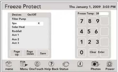
Use Freeze Protection menu to assign freeze protection to your pool and spa equipment. When a piece of equipment is assigned to freeze protection, it will turn on when the AquaLink RS detects freezing conditions. The main filter pump is freeze-protected as a default.
Activation temperature can be adjusted between 34^ F and 42^ F. Default freeze protection activation temperature is 38^ F and will deactivate within 2^ F.
10.11.1 To Set Up Freeze Protection
The FREEZE PROTECT menu can be accessed from the SYSTEM SETUP screen as well as the LABEL AUXILIARES screen.
MENU > SYSTEM SETUP > FREEZE PROTECT
Touch the FREEZE PROTECT button on the SYSTEM SETUP menu to display the FREEZE PROTECT menu.
MENU > SYSTEM SETUP > LABEL AUX
From the SYSTEM SETUP screen, touch the LABEL AUX button to display the LABEL AUXILIARIES screen.
Touch the FREEZE PROTECT button on the LABEL AUXILIARIES menu to display the FREEZE PROTECT menu.
Select any piece of equipment in the DEVICE list and change the temperature using the numeric keypad. Once the temperature is set, touch the ENTER button to move to the next screen to assign freeze protection to a selected piece of equipment. If an incorrect value was entered, touch the CLEAR button on the keypad and try again.
NOTE The filter pump is always assigned to freeze protection.
Important Information on Freeze Protection
Freeze protection is intended to protect equipment and plumbing for short periods of freezing only. It does this by activating the filtration pump and circulating the water to prevent freeze inside equipment or plumbing. Freeze protection does not guarantee that equipment will not be damaged by extended periods of freezing temperatures or power outages. In these conditions, the pool and spa should be shut down completely (e.g. drained of water and closed for the winter) until warmer weather exists.
10.12 Assign JVAs
The ASSIGN JVAs menu allows Jandy Valve Actuators (JVAs) to be assigned to any auxiliary button. This means that whenever you press that auxiliary button, a valve turns. On pool/spa combination models, there are commonly two extra JVAs that can be assigned to auxiliary buttons: the Cleaner JVA and the Solar JVA.
On pool/spa only models, there are four JVAs that can be assigned to auxiliary buttons. The installer must set these JVAs for this feature to operate correctly. Assigning JVAs lets the owner control certain features like diverting water to a waterfall or bank of spa jets.
Multiple JVAs can be assigned to one auxiliary button without extra hardware.
10.12.1 To Set Up Assign JVs
MENU/HELP > SYSTEM SETUP > ASSIGN JVs
Touch the ASSIGN JVs button on the SYSTEM SETUP screen to display the ASSIGN JVs menu.
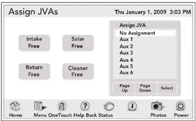
Touch the JVA button you wish to assign. Touch SAVE when finished.
NOTE If a solar sensor is installed, the solar JVA will automatically be assigned and will be marked as USED.
10.13 Dusk Setup
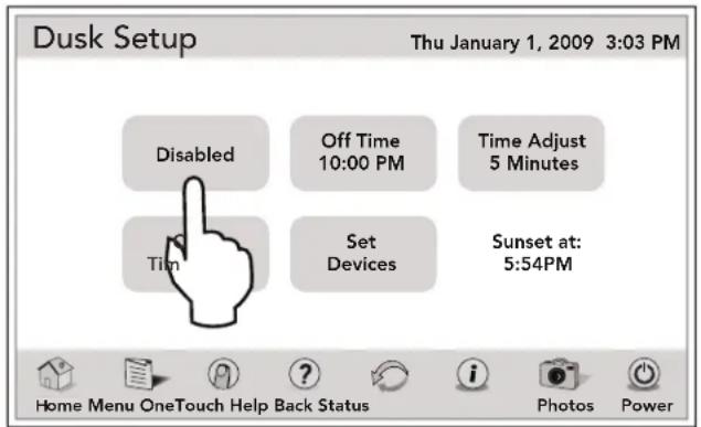
The DUSK SETUP screen is used to set a device to automatically turn on after sunset.
On the DUSK SETUP screen, you can set the duration, a time adjust value if you live between major city selections or in a heavily shaded area, and set specific devices.
NOTE Time and Date must be correct. See Section 4.4, "To Set Up Date/Time".
MENU > SYSTEM SETUP > DUSK SETUP
From the SYSTEM SETUP screen, touch the DUSK SETUP button to display the DUSK SETUP screen. Toggle the ENABLED/DISABLED button and select your choice.
10.13.1 Dusk Setup Off Time
From the DUSK SETUP screen, touch the OFF TIME button to display the DUSK SETUP OFF TIME screen as shown below.
On this screen, touch the CLEAR button to erase existing time. Use the numeric keyboard to enter new off time. Toggle the AM/PM button and select your choice. Touch the ENTER button to save new off time.
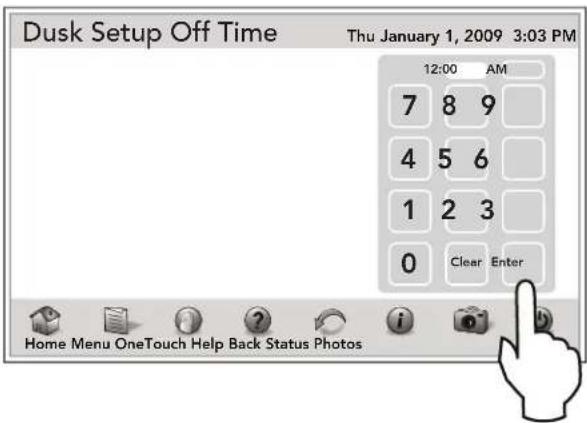
10.13.2 City/Time Zone
From the DUSK SETUP screen, touch the CITY/TIME ZONE button to display the screen as shown below.
On this screen, touch the city and choose the time zone. Use the PAGE UP/PAGE DOWN to view additional cities. Touch the SAVE button to save new setup.
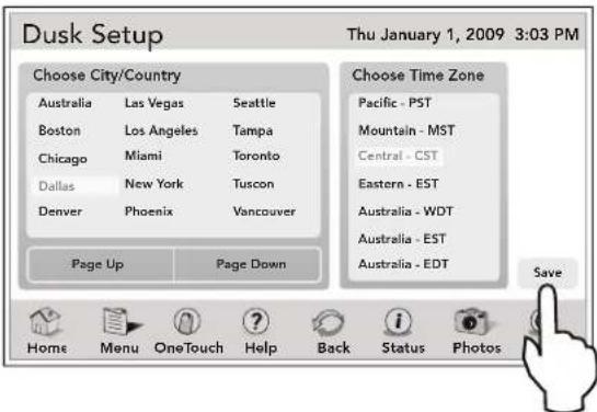
10.13.3 Assign Devices
From the DUSK SETUP screen, touch the SET DEVICES button to display the screen as shown below.
On this screen, touch the selected device to set it ON or OFF. Use the PAGE DOWN/PAGE UP to view additional devices. Touch the SAVE button to save new setup.
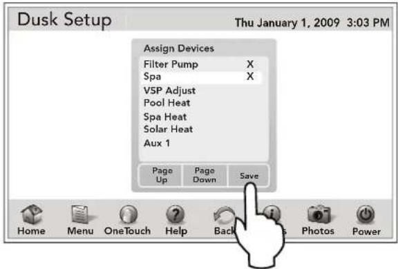
10.14 All Off Time
The ALL OFF TIME is used to direct the system to turn everything off at a specific time everyday.
10.14.1 To Set Up All Off Time
MENU > SYSTEM SETUP > ALL OFF TIME
From the SYSTEM SETUP screen, touch the ALL OFF TIME button to display the ALL OFF SETUP screen. On this screen, touch the ON/OFF button and set as desired.
If ALL OFF is ON, you need to set the time to turn all pool equipment off. Use the numeric keypad to enter new time. Touch ENTER when finished.
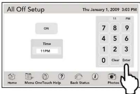
NOTE With this feature you can only set the hour value of the time - no minutes. The minutes will always be zero (0).
10.15 Pump Lockout
The PUMP LOCKOUT menu allows you to enable (pump off) or disable (pump stays on) when valves are rotating from pool to spa.
10.15.1 To Set Up Pump Lockout
MENU > SYSTEM SETUP > PUMP LOCKOUT
From the SYSTEM SETUP screen, touch the PUMP LOCKOUT button to enable the pump lockout.
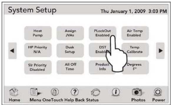
10.16 Daylight Savings Time (DST)
The DAYLIGHT SAVINGS menu enables the automatic adjustment for DST.
10.16.1 To Set Up DST
MENU > SYSTEM SETUP > DST
From the SYSTEM SETUP screen, toggle the DST button and select your choice.
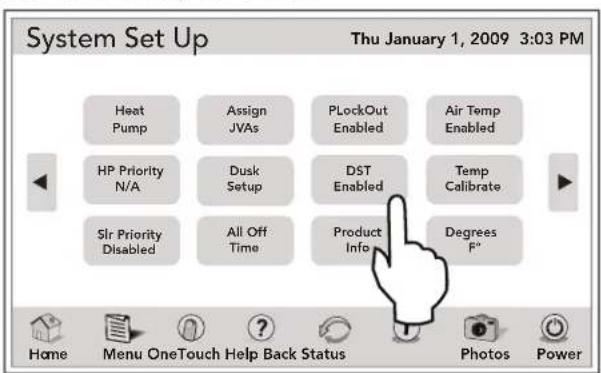
10.17 Product Information
The PRODUCT INFO screen is used to enter a custom product name, local service company name and telephone number.
MENU > SYSTEM SETUP > PRODUCT INFO
From the SYSTEM SETUP screen, touch the PRODUCT INFO button to display the PRODUCT INFO screen.
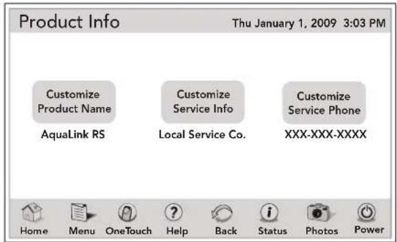
10.17.1 Customize Product and Service Info
SYSTEM SETUP > PRODUCT INFO > CUSTOM LABEL
From the PRODUCT INFO screen, touch the CUSTOMIZED PRODUCT NAME or the CUSTOMIZE SERVICE INFO button to view the CUSTOM LABEL screen. On this screen, enter your product or service information.
See Section 4.9.4, "Custom Label".
10.17.2 Customize Service Phone
SYSTEM SETUP > PRODUCT INFO
From the PRODUCT INFO screen, touch the CUSTOMIZED SERVICE PHONE to view the screen below. On this screen touch the CLEAR button to remove existing phone number. Use the numeric keyboard to enter new phone number. Touch the ENTER button to save new phone number.
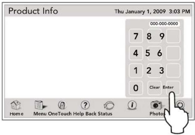
10.18 Air Temperature
Use the Air Temperature menu to turn the air temperature display on or off.
10.18.1 To Set Up Air Temperature
MENU > SYSTEM SETUP > AIR TEMP
From the SYSTEM SETUP screen, touch the AIR TEMP to enable the air temperature.
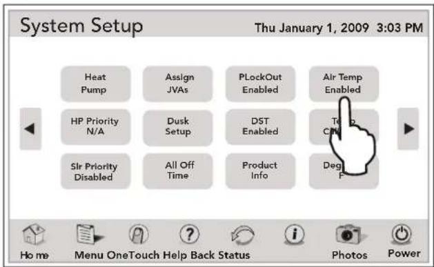
10.19 Temp Calibration
This menu allows adjustment of the temperature that is displayed on the AquaLink RS. The temperature can only be adjusted up four (4) degrees Fahrenheit or down four (4) degrees Fahrenheit.
10.19.1 To Set Up Calibration
MENU > SYSTEM SETUP > TEMP CALIBRATE
From the SYSTEM SETUP screen, touch the TEMP CALIBRATE button to display the WATER TEMP CALIBRATE screen. Touch the POOL or SPA button and use the arrow keys to set values.
NOTE If the temperature is off by more than four (4) degrees, contact your local service representative.
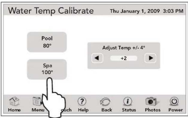
10.20 Degrees C/F
The Degrees C/F menu allows you to change the AquaLink RS temperature display from Fahr en heit to Celsius or vice versa. When changing from Fahrenheit to Celsius, you will have to re-enter the temperature settings.
10.20.1 To Set Up Degrees
MENU > SYSTEM SETUP > DEGREES
From the SYSTEM SETUP screen, toggle the DEGREES button to set the desired temperature setting.
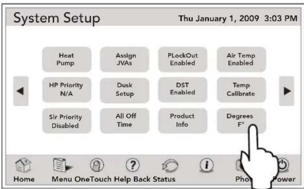
10.21 In-Floor Cleaning
This menu is used to enable or disable the automatic in floor cleaning feature. When enabled, the AquaLink RS rotates the in-floor Jandy valve actuators (JVAs) every 20 minutes. In-floor cleaning only works when the filter pump is on.
NOTE If activated this circuit will utilize the solar JVA relay socket and circuit to control the in-floor valve unless a solar sensor is installed, then the circuit reverts to AUX 3.
10.21.1 To Set Up In Floor Cleaning
MENU > SYSTEM SETUP > IN-FLOOR
From the SYSTEM SETUP screen, touch the IN-FLOOR button to enable the in-floor cleaning feature.
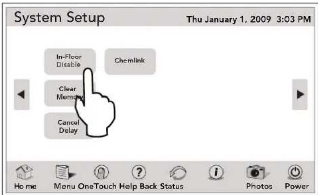
10.22 Clear Memory
The CLEAR MEMORY menu will clear all stored values from the AquaLink RS memory. All settings will be reset to their default settings. Stored values include auxiliary labels, all programs, freeze protection settings, remote settings, and thermostat settings. The time and date will not be cleared.
10.22.1 To Set Up Clear Memory
MENU > SYSTEM SETUP > CLEAR MEMORY
From the SYSTEM SETUP screen, touch the CLEAR MEMORY button and a dialog box will appear. Touch the YES button to clear memory. Touch the NO button to keep all stored settings unchanged. Clearing memory will erase all schedules, auxiliary labels, and system settings. The date and time will remain.
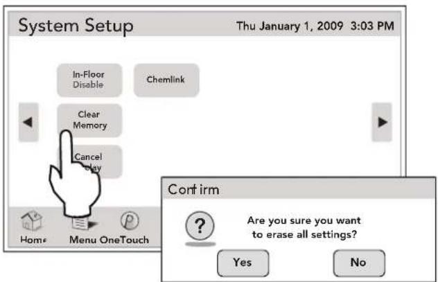
10.23 Cancel Delay
NOTE This feature is for use by service personnel only.
MENU > SYSTEM SETUP > CANCEL DELAY
From the SYSTEM SETUP screen, touch the CANCEL DELAY button.
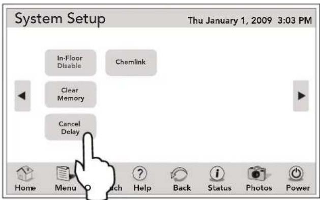
NOTE CANCEL DELAY should only be used by authorized service personnel. It should not be used during normal system operation.
Section 11. Heat Pump Setup
11.1 Solar Priority/Heat Pump Priority
The SOLAR PRIORITY/HEAT PUMP menu allows the system to use SOLAR HEAT/HEAT PUMP primarily. If Solar Heat is no longer available, the system will automatically switch to the alternate heat source.
MENU > SYSTEM SETUP > SOLAR PRIORITY
From the SYSTEM SETUP screen, touch the SOLAR PRIORITY button to enable the solar priority feature.
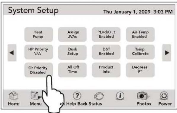
When solar and heater are enabled the solar will heat the water until either the thermostat setting has been reached or solar heat is no longer available. If the solar panel is not hot enough, solar heat will shut off and the other heat source (usually gas heater) will take over to bring the water up to the thermostat setting. This menu is used to ENABLE or DISABLE the solar priority.
NOTE Depending on the position of DIP switch S2-1 and the presence of a solar or heat pump sensor, SOLAR PRIORITY or HEAT PUMP PRIORITY may be displayed on the SYSTEM SETUP menu. It is not possible to have both SOLAR PRIORITY and HEAT PUMP PRIORITY displayed on SYSTEM SETUP MENU at the same time. It is one or the other.
11.2 Heat Pump (Heat Mode)
NOTE This equipment may not be part of your system. Please check with your installer.
The HEAT MODE selection controls the heat pump operation.
11.2.1 Heat Pumps Controlled by Extra Aux/Solar Boost Relay
In order to use the heat pump, the filter pump must be turned on and the heat pump must be in HEAT MODE, and the switch on the heat pump on the equipment pad must also be set to HEAT MODE.
NOTE HEAT PUMP takes the place of EXTRA AUX or SOLAR HEAT. It is not possible to have any two of these on the EQUIPMENT ON/OFF menu at the same time.
To operate the HEAT PUMP in this type of configuration, set the DIP switch S2-1 to ON and connect the HEAT PUMP temperature sensor to the SOLAR SENSOR input.
11.2.2 Heat Pumps Controlled by the RS485 Interface
In order to use the heat pump, the filter pump must be turned on and the heat pump must be in the HEAT MODE.
NOTE In this configuration, it is possible to have the HEAT PUMP and SOLAR HEAT on the DEVICES ON/OFF at the same time.
NOTE If both HEAT PUMP and SOLAR HEAT are to be controlled by the system then set the DIP switch S2-1 to OFF and connect the SOLAR SENSOR to the SOLAR SENSOR input.
NOTE If SOLAR HEAT is not to be controlled by the system then set the DIP switch S2-1 to ON and connect the HEAT PUMP temperature sensor to the SOLAR SENSOR input.
11.2.3 Heat Mode
MENU > SYSTEM SETUP > HEAT PUMP
From the SYSTEM SETUP screen, touch the HEAT PUMP button to display the HEAT PUMP SETUP screen.
From the HEAT PUMP SETUP screen, touch the HEAT MODE button to set the heat temperature.
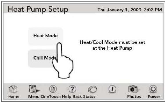
Use the numeric keypad to enter the new temperature, and then touch the ENTER button to save it.
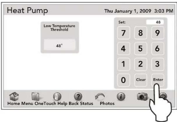
If the heat pump is not part of the system, the following warning message will be displayed.
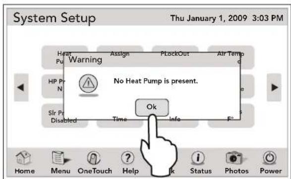
flowchart
graph TD
    A["Heat Pu"] --> B["Warning"]
    B --> C["Assign"]
    C --> D["PlugOut"]
    D --> E["Air Temp"]
    F["HP Pr N"] --> G["No Heat Pump is present."]
    H["Slr Pr Disabled"] --> I["Time"]
    I --> J["Info"]
    J --> K["F°"]
    L["Ok"] --> M["Hand Clicking"]
    style A fill:#f9f,stroke:#333
    style B fill:#ccf,stroke:#333
    style C fill:#cfc,stroke:#333
    style D fill:#fcc,stroke:#333
    style E fill:#cff,stroke:#333
    style F fill:#ffc,stroke:#333
    style G fill:#cfc,stroke:#333
    style H fill:#fcc,stroke:#333
    style I fill:#cfc,stroke:#333
    style J fill:#cfc,stroke:#333
    style K fill:#fcc,stroke:#333
    style L fill:#ffc,stroke:#333
    style M fill:#cfc,stroke:#333
11.3 Heat Pump (Chiller Mode)
NOTE This equipment may not be part of your system. Please check with your installer.
The CHILLER selection controls the chilling operation of the heat pump.
11.3.1 Heat Pumps (Chiller) Controlled by the Extra Aux/Solar Boost Relay
In order to use the chiller mode of the heat pump, the filter pump must be turned on and the heat pump must be in CHILLER MODE, and the switch on the heat pump on the equipment pad must also be set to CHILLER MODE.
NOTE CHILLER takes the place of EXTRA AUX or SOLAR HEAT. It is not possible to have any two of these on the DEVICES ON/OFF menu at the same time. To operate the HEAT PUMP in this type of configuration, set the DIP switch S2-1 to ON and connect the HEAT PUMP temperature sensor to the SOLAR SENSOR input.
IMPORTANT Information on Chiller
You must manually change the setting at your heat pump from Heat to Chiller.
11.3.2 Heat Pumps (Chiller) Controlled by the RS485 Interface
The CHILLER selection controls the chilling operation of the heat pump. In order to use the chiller mode of the heat pump, the filter pump must be turned on and the heat pump must be enabled. The heat pump will switch to chill automatically when the water temperature rises above the chiller temperature set point.
NOTE In this configuration, it is possible to have HEAT PUMP/CHILLER and SOLAR HEAT on the EQUIPMENT ON/OFF at the same time.
NOTE If both HEAT PUMP/CHILLER and SOLAR HEAT are to be controlled by the system then set the DIP switch S2-1 to OFF and connect the SOLAR SENSOR to the SOLAR SENSOR input.
NOTE If SOLAR HEAT is not to be controlled by the system then set the DIP switch S2-1 to ON and connect the HEAT PUMP temperature sensor to the SOLAR SENSOR input.
NOTE If the water temperature is greater than the chiller temperature setpoint then CHILLER is displayed on the EQUIPMENT ON/OFF screen. Otherwise HEAT PUMP is displayed.
11.3.3 Chill Mode
MENU > SYSTEM SETUP > HEAT PUMP
From HEAT PUMP SETUP screen, touch the CHILL MODE button to enable/disable the CHILLER. The CHILLER uses the desired chilling temperature set point.
NOTE The system will force the Chiller set point to always be at least five (5) degrees Fahrenheit higher than the heater set point.
NOTE If the end time of an enabled program overlaps the start time of a second enabled program, the second program will be delayed until the first program completes, and the master valve will remain activated between programs.
Section 12. Variable Speed Pump Setup
NOTE This equipment may not be part of your system. Please check with your installer.
A VARIABLE SPEED PUMP can be programmed to run at any one of its eight (8) speeds.
Power to the variable speed pump is switched on/off by a relay, so to program the pump you need to set a program time for the relay, and for any speeds that you wish to run during the pump's on cycle.
In the example shown below the variable speed pump is used for pool filtration, so it will be powered from the FILTER PUMP relay. Therefore, to program the variable speed pump you must first set a program time for the FILTER PUMP relay, then you need to program the desired pump speeds to turn on/off during the FILTER PUMP cycle.
If you do not program any speeds to run during the filtration cycle, then by default the variable speed pump will run at the POOL speed setting during its filtration cycle.
Example:
- The total length of the filtration cycle is to be from 8am to 5pm. So program the FILTER PUMP to turn on at 8am and to turn off at 5pm.
- To run the variable speed pump at the SPEED3 setting from 8am to 1pm, select VSP SPD1 PGM, then select SPEED3, program it to turn on at 8am and off at 1pm.
- To run the variable speed pump at the SPEED4 setting from 1pm to 5pm, select VSP SPD1 PGM, then select SPEED4, program it to turn on at 1pm and off at 5pm.
| ON OFF DESCRIPTION | ||
| FILTER PUMP 8AM 5PM | Total duration of filtration cycle | |
| SPEED3 8AM 1PM Pump | runs at the | SPEED3 setting |
| SPEED4 1PM 5PM Pump | runs at the | SPEED4 setting |
The VAR SPEED PUMP menu is used to select the variable speed pump type (Jandy ePump™, Pentair® IntelliFlo® VF, Pentair IntelliFlo VS, or Pentair IntelliPro VS) and to select the various pump settings. To interface the IntelliPro VS, select IntelliFlo VS.
12.1 To Select the Pump/Model
MENU > SYSTEM SETUP > VSP SETUP
From the SYSTEM SETUP screen, touch the VSP SETUP button to display the VSP SETUP screen.
From the VSP SETUP screen, touch the PUMP/MODEL button to display the SELECT VSP screen.
Touching the RESTORE SPD DEFAULTS button will set the pump speeds, prime speeds and prime duration to their factory default settings.
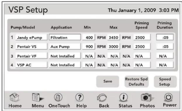
In the PUMP MODEL list, select the variable speed pump type and touch the SELECT button to save it.
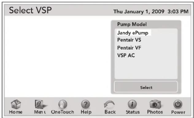
12.2 To Set Up the Pump Application
The AquaLink RS can control up to four (4) variable speed pumps. In the PUMP SETUP menu the user can select each pump (1-4) and configure how the pump(s) are to be used. For example if the pump is to be used for pool/spa filtration then you would select FILTRATION as the pump application. If the pump is to be used for a water feature then you would select AUX. PUMP as the pump application. The default setting is NOT INSTALLED.
| COMBO POOL | SPAONLY | DUALEQUIPMENT |
| FILTRATION FILTR | ATION POOL PUMP | |
| AUX. PUMP AUX. F | UMP SPA PUMP | |
| NOT INSTALLED N | NOT INSTALLED AUX. PUMP | |
| NOT INSTALLED |
If the system is not going to control a variable speed pump then leave the application set to NOT INSTALLED. If the system is going to control a variable speed pump, then you would set the application accordingly.
In the example below we are telling the system that it will be controlling one (1) variable speed pump.
MENU > SYSTEM SETUP > VSP SETUP
From the VSP SETUP screen, touch the APPLICATION button of the selected pump to display the VSP APPLICATION screen.
From the PUMP APPLICATION list choose the desired pump application and touch the SELECT button to save it.
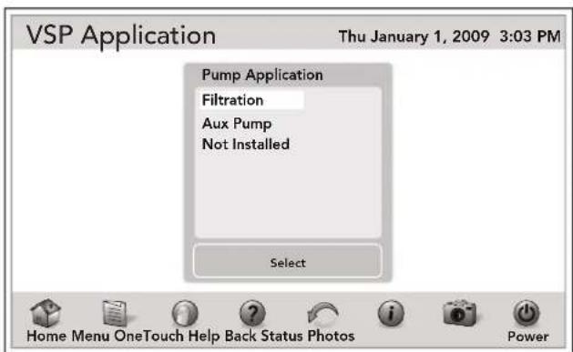
12.3 To Set Up MIN/MAX Parameters
This menu allows the user to set a global minimum and maximum speed or flow for the indicated pump. The SCALE setting is fixed to RPM for the Jandy ePump and the Pentair® IntelliFlo VF. The SCALE setting is fixed to GPM for the Pentair IntelliFlo VF.
MENU > SYSTEM SETUP > VSP SETUP
From the VSP SETUP screen, touch the MIN / MAX button of the selected pump to display the VSP SET RPM screen.
From the VSP SET RPM screen, use the numeric keypad to enter the desired limit and touch the ENTER button.
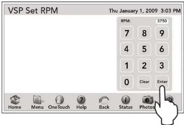
12.4 To Set Up the Priming Speed
MENU > SYSTEM SETUP > VSP SETUP
From the SYSTEM SETUP screen, touch the VSP SETUP button to display the VSP SETUP screen. From the VSP SETUP screen, touch the PRIMING SPEED button of the selected pump to display the SELECT VSP screen. Use the numeric keypad to set the desired priming speed.
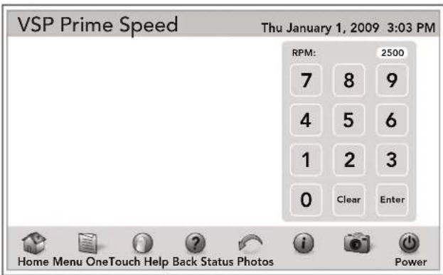
12.5 To Set Up the Priming Duration Time
MENU > SYSTEM SETUP > VSP SETUP
From the SYSTEM SETUP screen, touch the VSP SETUP button to display the VSP SETUP screen. From the VSP SETUP screen, touch the PRIMING DURATION button of the selected pump to display the VSP SET PRIMING DURATION screen. Use the numeric keypad to set the desired priming duration time.
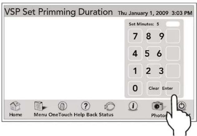
12.6 To Assign a Pump Speed to an AUX
MENU > SYSTEM SETUP > VSP SETUP
From the SYSTEM SETUP screen, touch the VSP SETUP button to display the VSP SETUP screen. From the VSP SETUP screen, on the AUX column touch an item to be assigned an AUX.
On the ASSIGN VSP to AUX/RELAY screen, touch the desired AUX and touch the SAVE button.
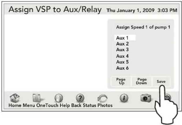
12.7 To Set Up Pump Speed
There are eight (8) default speed presets for each variable speed pump.
MENU > SYSTEM SETUP > VSP SETUP
From the VSP SETUP screen, touch SPEED SETUP button to display the VSP SPEED SETUP screen.
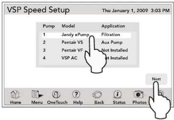
Select the pump/model and touch the NEXT button to display the eight (8) speed VSP SETUP screen.
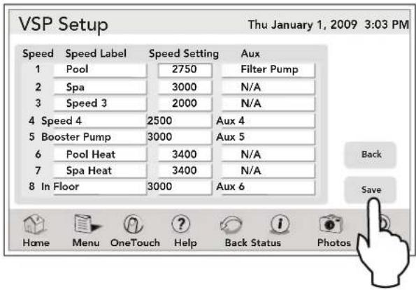
12.8 To Re-label the Speed Preset
Each of the eight (8) speed presets has a label and each of those labels can be changed from the default value.
MENU > SYSTEM SETUP > VSP SETUP
From the VSP SETUP screen, touch SPEED LABEL of the selected speed to display the VSP SPEED LABEL screen.
From the GENERAL LABELS list, highlight the desired device and touch the SAVE button. Use PAGE UP /PAGE DOWN to scroll though the list. If you want to assign a new label, touch the CUSTOM LABEL button.
See Section 4.9.4, "Custom Label".
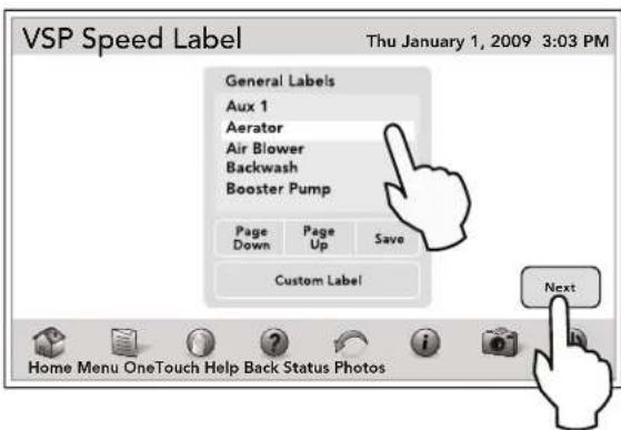
12.9 Default Preset Speed Labels (RS Combo and RS only)
When a pump is configured for FILTRATION, the speed presets will be labeled as shown in the table below. The presets can be relabeled.
| DEFAULT Labels when Pump is configured for FILTRATION | |||
| PRESET # | POOL/SPA COMBO | POOL/SPA ONLY | SPEED (RPM) |
| 1 POOL | POOL 1725 | ||
| 2 SPA | SPEED2 2750 | ||
| 3 SPEED3 or CLEANER(if dip S1-1 is on) | SPEED3 or CLEANER(if dip S1-1 is on) | 2750 | |
| 4 SPEED4 or SPILLOVER(if dip S1-3 is on) | SPEED4 | 2750 | |
| 5 POOL | HEAT TEMP1 2250 | ||
| 6 SPA | HEAT TEMP2 2250 | ||
| 7 SOLAR | HEAT(if dip S1-7 is off)or HEATPUMP(if dip S1-7 is on)or SPEED7 | SOLAR HEAT(if dip S1-7 is on) orHEATPUMP(if dip S1-7 is on) or SPEED7 | 2750 |
| 8 INFLOOR | INFLOOR 2750 | ||
Preset 1:
The default label for preset #1 is POOL. This label is tied to the pool filtration mode. Anytime the pool pump is supposed to turn on, this preset is selected.
Preset 2:
On combo systems the default label for preset #2 is SPA. This label is tied to the spa filtration mode, anytime the spa pump is supposed to turn on, this preset is selected.
Preset 3:
On combo systems, if dip switch S1-1 is ON, then the default label for this preset is CLEANER. Anytime the cleaner mode is turned on the pump will run at the speed setting of this preset.
On a combo system, if dip switch S1-1 is OFF, then the default label for this preset is SPEED3.
Preset 4:
If dip switch S1-3 is ON, then the default label for this preset is SPILLOVER. Anytime the spillover mode is turned on the pump will run at the speed setting of this preset.
If dip switch S1-3 is OFF, then the default label for this preset is SPEED4.
Preset 5:
On pool/spa combo systems the default label is POOL HEAT. When the pool heater is enabled the pump will run at this speed.
On pool/spa only systems the default label is TEMP1. When the pump is running and the heater set point TEMP1 is enabled, then the pump will run at this preset.
Preset 6:
On pool/spa combo systems the default label is SPA HEAT. When the system is in the SPA mode and the SPA HEATER is enabled then the pump will run at this speed.
On pool/spa only systems the default label is TEMP2. When the pump is running and the heater set point TEMP2 is enabled, then the pump will run at this preset.
Preset 7:
If the system is in the SOLAR HEAT mode or the HEAT PUMP mode then the pump will run at this preset speed. If the system is not configured for solar heat or a heat pump then the default label will be SPEED7.
Preset 8:
When the In-Floor clean mode is enabled and the pump is running, it will be running at this preset speed.
12.9.1 Default Preset Speed Labels (Dual Equipment)
When a pump is configured to be either a POOL PUMP or a SPA PUMP, the speed presets will be labeled as shown in the table below. The presets can be relabeled but the operation of the speeds may be changed by doing so.
| DEFAULT Labels and Speeds when Pumps are configured as POOL PUMP and SPA PUMP (Dual Equipment Systems) | |||
| PRESET # | POOL PUMP SPA PUMP SPEED | ||
| 1 POOL | SPEED1 1725 | ||
| 2 SPEED2 | SPA 2750 | ||
| 3 SPEED3 | or CLEANER(if dip S1-1 is on) | SPEED3 2750 | |
| 4 SPEED4 | SPEED4 2750 | ||
| 5 POOL | HEAT SPEED5 2250 | ||
| 6 SPA | HEAT SPA HEAT 2250 | ||
| 7 SOLAR | HEAT(if dip S1-7 is off)or HEATPUMP(if dip S2-7 is on)or SPEED7 | SPEED7 2750 | |
| 8 INFLOOR | SPEED8 2750 | ||
Preset 1:
On a dual equipment system when a pump is configured as a POOL PUMP, the default label for preset #1 is POOL. This label is tied to the pool filtration mode. Anytime the pool pump is supposed to turn on, this preset is selected.
On a dual equipment system when a pump is configured as a SPA PUMP, the default label for preset #1 is SPEED1.
Preset 2:
On a dual equipment system when a pump is configured as a SPA PUMP, the default label for preset #2 is SPA. This label is tied to the spa filtration mode. Anytime the spa pump is supposed to turn on, this preset is selected.
On a dual equipment system when a pump is configured as a POOL PUMP, the default label for preset #2 is SPEED2.
Preset 3:
For the pool pump, if dip switch S1-1 is ON, then the default label for this preset is CLEANER. Anytime the cleaner mode is turned on the pump will run at the speed setting of this preset. If dip switch S1-1 is OFF, then the default label for this preset is SPEED3.
For the spa pump the default label is SPEED3.
Preset 4:
The default label is SPEED4.
Preset 5:
For the pool pump the default label is POOL HEAT. When the pool heater is enabled the pump will run at this speed.
For the spa pump the default label is SPEED5.
Preset 6:
For the pool pump the default label is SPEED6.
For the spa pump the default label is SPA HEAT. When the spa heater is enabled the pump will run at this speed.
Preset 7:
For the pool pump, if the system is in the SOLAR HEAT mode or the HEAT PUMP mode then the pump will run at this preset speed. If the system is not configured for solar heat or a heat pump then the default label will be SPEED7.
For the spa pump the default label is SPEED7.
Preset 8:
For the pool pump, when the In-Floor clean mode is enabled and the pump is running, it will be running at this preset speed.
For the spa pump the default label is SPEED8.
Section 13. Sprinkler System Setup
NOTE This equipment may not be part of your system. Please check with your installer.
In addition to the individual sprinkler programming, the user may enable or disable all sprinkler programs, cancel sprinkler programs for 24 hours, or manually start one or more sprinkler programs.
13.1 Running the Sprinkler System
NOTE If there are no sprinkler programs set to ON, then SPRINKLERS does not appear in the DEVICES list.
HOME > OTHER DEVICES ON / OFF > SPRINKLERS
From the HOME screen, touch the OTHER DEVICES ON/OFF button to display the DEVICES screen shown below.
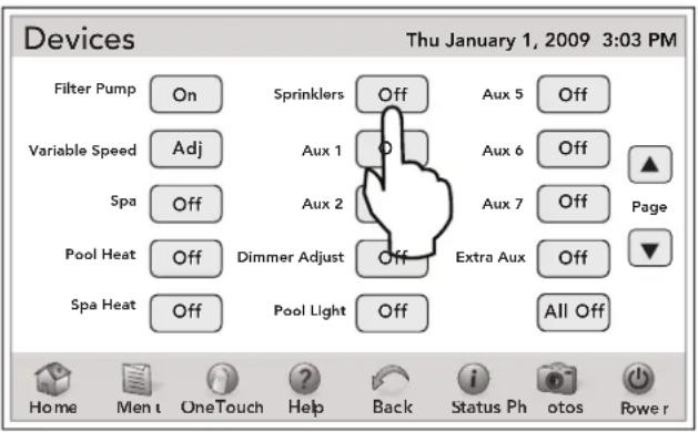
13.1.1 Cancel Today - 24 Hour Sprinkler Delay
This feature is used to disable the sprinklers for a period of 24 hours. All pending programs are canceled and the system enters the delay state. After 24 hours the system returns to the ENA state.
The 24-hour time delay is reset each time CANCEL TODAY is selected.
NOTE This feature may also be used to quickly turn off all sprinkler valves.
OTHER DEVICES ON / OFF > SPRINKLERS > CANCEL TODAY
From the DEVICES screen, touch the SPRINKLERS button to display SPRINKLER OPERATION screen. Touch the CANCEL TODAY button to set a 24 - hour sprinkler delay.
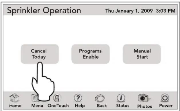
13.1.2 Enabling the Sprinkler System
To automatically run programs at their start times, the sprinkler control system must be in the enabled state.
OTHER DEVICES ON/OFF > SPRINKLERS > PROGRAMS
To enable the sprinkler system, touch the PROGRAMS button, on the SPRINKLER OPERATION screen.
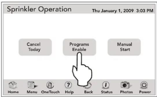
13.1.3 Manually Starting a Sprinkler Program
Selecting MANUAL START presents the user with a screen providing the option to start all enabled programs, or any individual enabled program, or a single valve.
Continue on the screen shown below and touch the desired PROGRAM # and touch the START button. The program is started immediately and runs to completion unless interrupted by the user.
If ALL PROGRAMS is selected, all enabled programs are run in succession, in numerical order. The sprinkler system enters ENA state at the end of manually started programs.
NOTE If a program is not set to ON, it does not appear in the MANUAL START list.
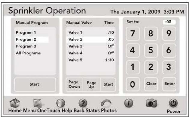
13.1.4 Disabling the Sprinkler System
When the sprinkler control system is disabled, all running programs are canceled and no programs will run, regardless of their individual ON/OFF setting.
OTHER DEVICES ON/OFF > SPRINKLERS > PROGRAMS
To disable the sprinkler system, touch the PROGRAMS DISABLE button in the SPRINKLER OPERATION screen.
After DISABLE PROGRAMS is selected, the system enters the OFF state.
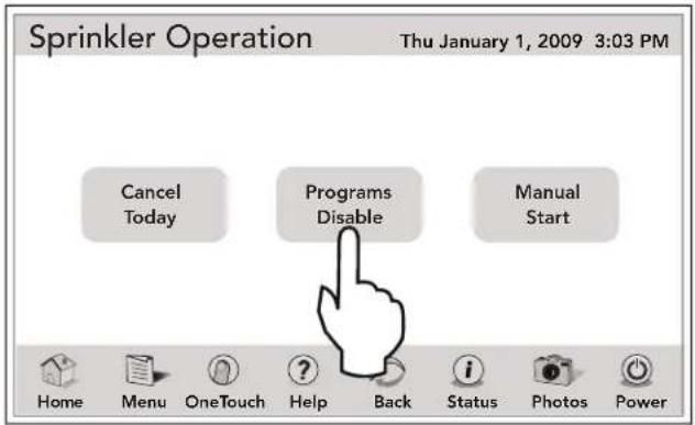
NOTE This equipment may not be part of your system. Please check with your installer.
13.2 Programming Sprinkler System
The AquaLink Touch Controller offers a versatile, easy to use features to program your sprinkler system. Up to three (3) programs can be scheduled with different Run Days, Start Times and Durations.
MENU > SYSTEM SETUP > SPRINKLER SETUP
From the SYSTEM SETUP screen, touch the SPRINKLER SETUP button to display the screen shown below.
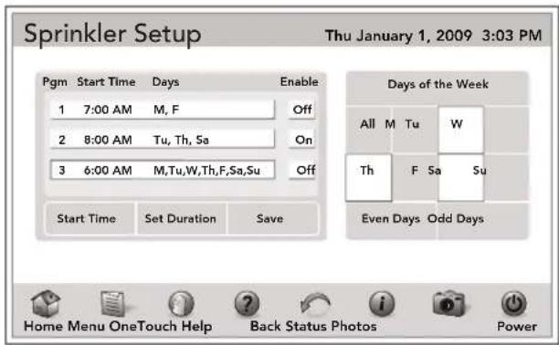
13.2.1 To Set Up the Water Days
You can choose All to run the program all week long, Even Days, Odd Days or select the desired day(s) to run the enable programs.
From the SPRINKLER SETUP screen, enable the program # by touching the ON button.
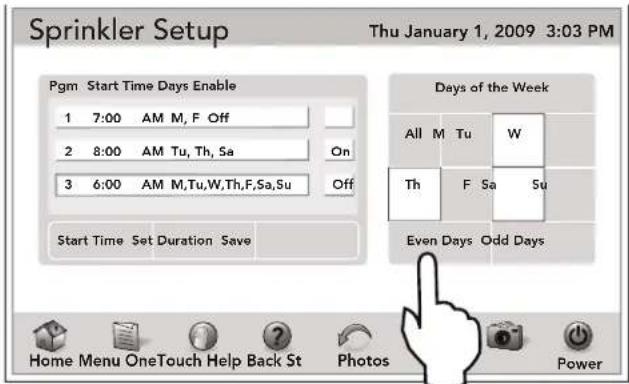
13.2.2 To Set Up the Sprinklers Program Start Time menu
From the SPRINKLER SETUP screen, touch the START TIME button to display the numeric keyboard. Enter the start time and touch the ENTER button to save it.
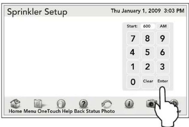
13.2.3 To Set Up the Sprinkler Valve Duration Time
The Sprinkler Control module will control up to eight (8) valves, plus one (1) master valve. When a program is run, the master valve always activates 1-2 seconds before the first programmed valve in the program. Valves are then activated in numerical order for a time equal to their duration setting. There is a 1-2 second delay between valve activations.
Valve durations are adjustable from OFF to 240 minutes, in increments of one (1) minute from OFF to 10 minutes, increments of 10 minutes from 10 to 60 minutes, and increments of 30 minutes from 60 to 240 minutes (4 hours).
After setting the water DAYS, touch the DURATION button to display the SPRINKLER SET DURATION screen. Touch the PROGRAM button to be set up. Touch the PAGE UP/DOWN button to select the desired VALVE. Touch the DURATION time and using the numeric keyboard enter the new duration time. Touch the ENTER button when finished.
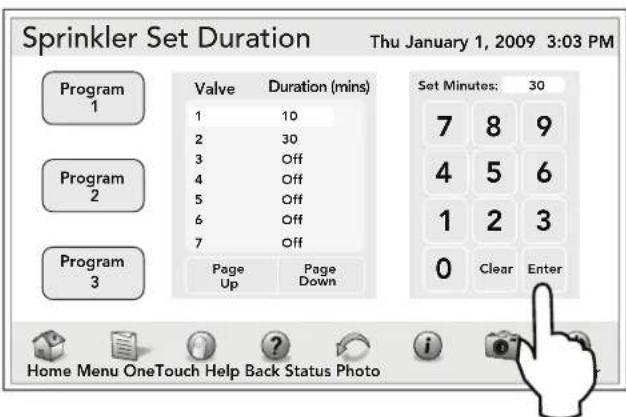
If you enter a value greater than 240 minutes, the following error screen will be displayed.
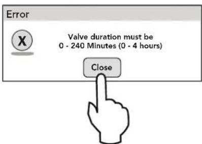
Section 14. ChemLink™ Setup
The ChemLink controller automatically monitors and maintains both the sanitizer and the pH balance in swimming pools, spas, or any circulating water system that requires water chemistry management.
14.1 To Set Up the ChemLink
NOTE Check with the installer before making changes to the SYSTEM SETUP.
SYSTEM SETUP > SET CHEMLINK > CHEMLINK
From the SYSTEM SETUP screen, touch the SET CHEMLINK button to display the CHEMLINK setup screen.
As shown below, the CHEMLINK setup screen provides links to set up the ORP/pH balances, ORP/pH manual feeds, and level switch. Also, provides the current values for the ORP and pH levels.
If only one chemLink is present in the system, the CHEMLINK setup screen is displayed automatically.
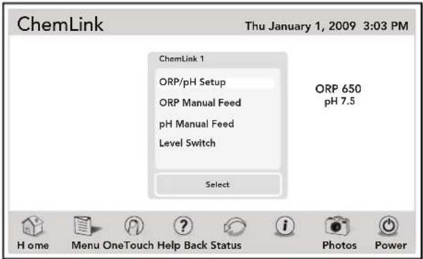
If more than one chemlink is present, the screen will display the links for additional chemlinks. To continue, touch the button of the chemlink to be configured and the CHEMLINK ORP/pH setup screen will appear.
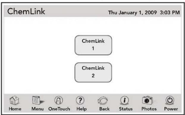
14.2 To Configure the ORP Controller
From the CHEMLINK setup screen, highlight the ORP/pH SETUP item and then touch SELECT to display the CHEMLINK ORP/pH setup screen.
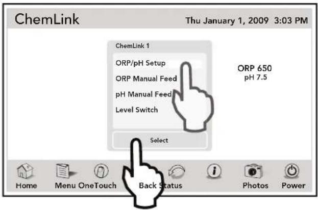
By default, the ORP configuration screen will appear as shown below. Use this screen as follows:
- Touch ORP to configure the ORP controller (default).
- Touch pH to configure the pH controller.
- Use PAGE UP/DOWN to see additional items.
- Highlight item to be configured.
- Use the UP/DOWN arrows to adjust values.
- Touch SAVE when finished.
NOTE Make sure you touch the SAVE button when finished. Otherwise, your new setting will be lost.
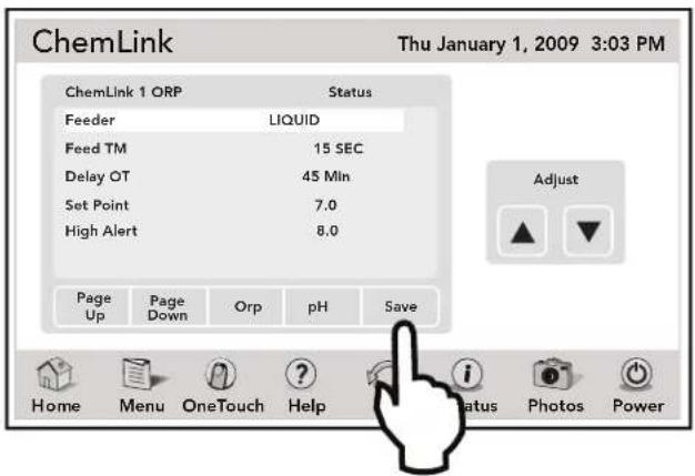
14.2.1 ORP Feeder Type
Depending on your installation, the AquaLink Touch may display the following feeders:
- NONE - Default setting.
- SALT - For salt water chlorinators.
- ERO LP - Non typical application.
- MBV - Non typical application.
- ERO HP - Non typical application.
- LIQUID - For liquid peristaltic pumps.
- GRAN - For PolarfsG1000 dichor feeders.
From the CHEMLINK ORP setup screen, highlight the FEEDER type. Use the UP and DOWN arrows to select the feeder type. Touch SAVE when finished.
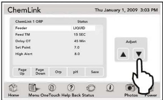
14.2.2 ORP Feeder Times
The feeders times, sets the amount of time the controller activates the feeder per dose.
From the CHEMLINK ORP setup screen, highlight the FEED TM values. Use the UP and DOWN arrows to adjust the feed times values. Touch SAVE when finished.
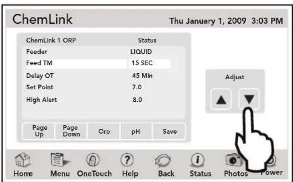
| Type | ERO LP/MBV/ERO HP | Liquid |
| Default | Do not use | 30 Sec |
| Range | .05 Sec to CONT |
14.2.3 ORP Delay On Time
From the CHEMLINK ORP setup screen, highlight the DELAY OT time. Use the UP and DOWN arrows to adjust the delay on time. Touch SAVE when finished.
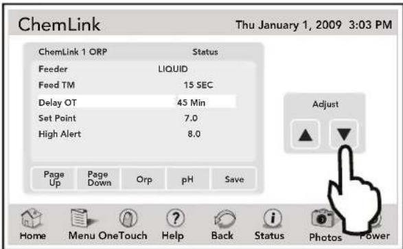
| Type | Salt | ERO LP/ MBV/ ERO HP | Liquid | Gran |
| Default Overfeed Off | Do not use | 10 Min | 30 Min | |
| Range | 1-99 Min | 1-99 Min | ||
OVERFEED: Salt only. Will alarm and not feed if ORP has activated for too long, preventing damage to the cell.
FEED DELAY: Sets the amount of time the controller waits to dose the pool again.
14.2.4 ORP Setpoint
This setting specifies the level of sanitizer to be maintained.
From the CHEMLINK ORP setup screen, highlight the SET POINT values. Use the UP and DOWN arrows to adjust the set point values. Touch SAVE when finished.
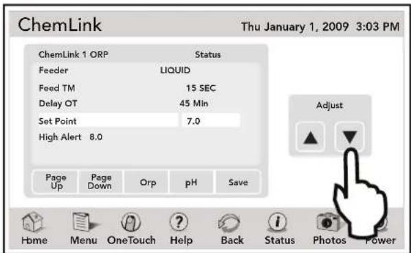
| Default | 650 |
| Range | 200 to 900 |
14.2.5 ORP Alarm - High Alert
The high alert alarm sets an alarm to deactivate the controller in the event of an ORP reading that is out of high range. This could be an indication of a mechanical malfunction in the feeding system.
From the CHEMLINK ORP setup screen, highlight the HI ALERT values. Use the UP and DOWN arrows to adjust the high alert values. Touch SAVE when finished.
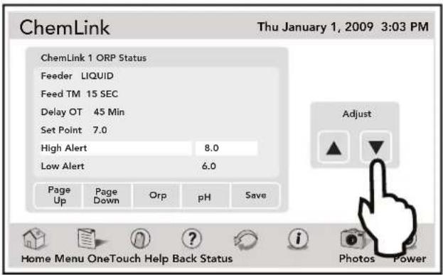
| Default | 950 |
| Range | 350 to 950 |
14.2.6 ORP Alarm - Low Alert
The low alert alarm sets an alarm to deactivate the controller in the event of an ORP reading that is out of low range. This could be an indication of a mechanical malfunction in the feeding system.
From the CHEMLINK ORP setup screen, highlight the LOW ALERT values. Use the UP and DOWN arrows to adjust the low alert values. Touch SAVE when finished.
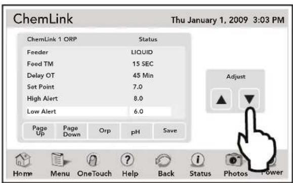
| Default | 100 |
| Range | 100 to 650 |
14.2.7 Wait or Stop pH
From the CHEMLINK ORP setup screen, highlight the WAIT PH/STOP PH entry. Use the UP and DOWN arrows to adjust the wait/stop pH entry. Touch SAVE when finished.
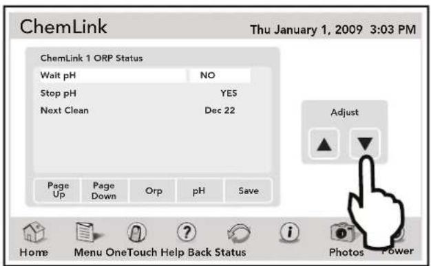
Wait for pH:
YES= ORP will not feed at the same time as pH. NO= ORP will feed regardless of when pH feeds. Default= YES
Stop for pH:
YES= ORP will not feed if the pH is out of range. NO= ORP will feed regardless of pH. Default= YES
14.2.8 ORP Next Cleaning
Manually set reminder to clean the ORP sensor. Enter Month, then Year for automatic reminder.
- Default - JAN 01 (essentially OFF).
From the CHEMLINK ORP setup screen, highlight the NEXT CLN date. Touch the UP or DOWN arrows to display numeric keyboard screen.
Using the numeric keyboard, touch clear to erase existing date. Enter new date in Month/Year format.
Touch ENTER when finished.
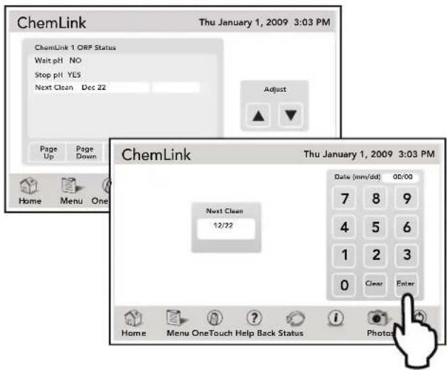
14.3 To Configure the pH Controller
From the CHEMLINK setup screen, touch the pH button to display the CHEMLINK pH setup screen. This screen provides the current settings for the pH levels.
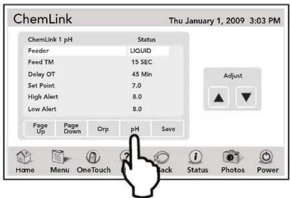
14.3.1 pH Feeder Type
Depending on your installation, the AquaLink Touch may display the following feeders:
- NONE - Default setting.
- ERO LP - Non typical application.
- MBV - Non typical application.
- ERO HP - Non typical application.
- GRAN - Non typical application.
- LIQUID - For liquid peristaltic pumps.
From the CHEMLINK pH setup screen, highlight the FEEDER type. Use the UP and DOWN arrows to select the feeder type. Touch SAVE when finished.
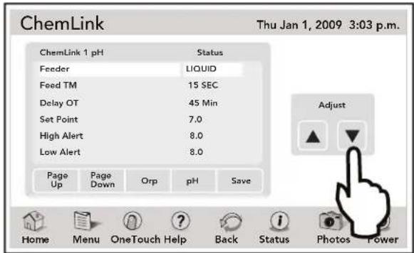
14.3.2 pH Feeder Times
The feeder times sets the amount of time the controller activates the feeder per dose.
From the CHEMLINK pH setup screen, highlight the FEED TM time. Use the UP and DOWN arrows to adjust the feed time. Touch SAVE when finished.
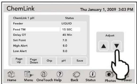
| Type | ERO LP/MBV/ERO HP | Liquid |
| Default | Do not use | 30 Sec |
| Range | .05 Sec to CONT |
14.3.3 pH Delay On Time
The delay on time sets the amount of time the controller waits to dose the pool again.
From the CHEMLINK pH setup screen, highlight the DELAY OT time. Use the UP and DOWN arrows to change this time. Touch SAVE when finished.
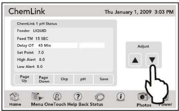
| Type | ERO LP/MBV/ERO HP | Liquid |
| Default | Do not use | 30 Sec |
| Range | .05 Sec to CONT |
14.3.4 pH Setpoint
This setting specifies the level of sanitizer to be maintained.
From the CHEMLINK pH setup screen, highlight the SET POINT values. Use the UP and DOWN arrows to adjust the SET POINT values.
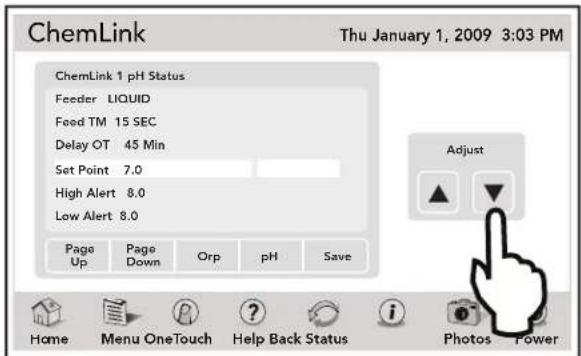
| Default | 7.5 |
| Range | 7.0 to 8.2 |
14.3.5 pH Alarm - High Alert
The high alert alarm sets an alarm to deactivate the controller in the event of a pH reading that is out of high range. This could be an indication of a mechanical malfunction in the feeding system.
From the CHEMLINK pH setup screen, highlight the HI ALERT values. Use the UP and DOWN arrows to change values. Touch SAVE when finished.
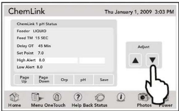
| Default | 8.4 |
| Range | 7.5 to 8.4 |
14.3.6 pH Alarm - Low Alert
The low alert alarm sets an alarm to deactivate the controller in the event of a pH reading that is out of low range. This could be an indication of a mechanical malfunction in the feeding system.
From the CHEMLINK pH setup screen, highlight the LOW ALERT setting. Use the UP and DOWN arrows to change this setting. Touch SAVE when finished.
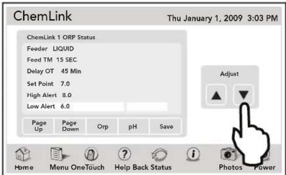
| Default | 6.8 |
| Range | 6.8 to 7.4 |
14.3.7 pH Acid or Base Feed
From the CHEMLINK pH setup screen, highlight the ACID/BASE entry. Use the UP and DOWN arrows to select new entry. Touch SAVE when finished.
- DEFAULT - Acid.
- ACID - Feeds acid to lower the pH.
- BASE - Feeds base material to raise the pH.
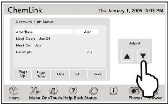
14.3.8 pH Next Cleaning
Manually set reminder to clean the pH sensor. Enter Month, then Year for automatic reminder.
- DEFAULT - JAN 01 (essentially OFF)
From the CHEMLINK pH setup screen, highlight the NEXT CLEAN date. Touch the UP or DOWN arrows to display numeric keyboard screen.
Using the numeric keyboard, touch clear to erase existing date. Enter new date in Month/Year format.
Touch ENTER when finished.
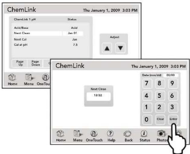
14.3.9 pH Next Calibration
Manually set reminder to clean the pH sensor. Enter Month, then Year for automatic reminder.
- DEFAULT - JAN 01 (essentially OFF)
From the CHEMLINK pH setup screen, Highlight the NEXT CAL date. Touch the UP or DOWN arrows to display numeric keyboard screen.
Using the numeric keyboard, touch clear to erase existing date. Enter new date in Month/Year format.
Touch ENTER when finished.
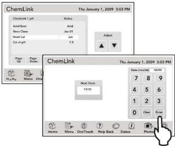
14.3.10 pH Calibration
This is calibration for pH reading. You can enter the actual pH here to adjust sensor reading.
- DEFAULT - 7.5
From the CHEMLINK pH setup screen, highlight the CAL AT PH settings. Use the UP and DOWN arrows to change this setting. Touch SAVE when finished.
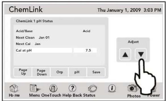
14.4 Manual Feed Activation
14.4.1 To Perform an ORP Manual Feed
From the CHEMLINK setup screen, highlight the ORP MANUAL FEED entry. A CONFIRM dialog box will appear, touch the YES button to proceed with the manual ORP feed.
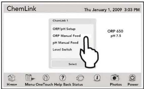
14.4.2 To Perform a pH Manual Feed
From the CHEMLINK setup screen, highlight the pH MANUAL FEED entry. A CONFIRM dialog box will appear. Touch the YES button to proceed with the manual pH feed.
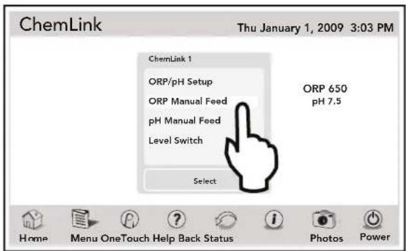
14.4.3 To Enable the ChemLink™ Feeder Tank Level Switch
This feature allows the use of an external, tank-mounted level switch to indicate when a liquid tank is empty to prevent the dry feeding of a peristaltic pump. These switches are an after-market product and not available through Jandy. There are only provisions for one (1) switch. The switch must be normally closed (NC).
From the CHEMLINK setup screen, highlight the LEVEL SWITCH entry. An 'X' on the display indicates the Level Switch is enabled. Touch the LEVEL SWITCH again to disable it.
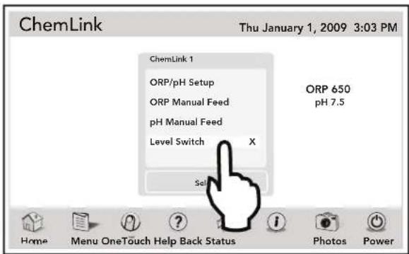
Section 15. Glossaries
15.1 Safety Delays and Lockouts
Lockouts
Any device can be locked out. This will prevent the locked out device from being turned on manually. However, the device will turn on/off when it is being controlled by a program.
Pool/Spa Switching Filter Pump Delay
The filter pump turns off while valves rotate between pool and spa to prevent damage to the pool equipment. The valves take 35 seconds to rotate between pool and spa; the filter pump will activate as soon as the valves have finished turning.
Heater Cool Down Delay
When the system is heating (water is circulating to the spa) and the Spa button is pressed, the system will remain in Spa Mode for five (5) minutes, and will continue to circulate the water. This delay allows water to cool the heater down by circulating water through it, preventing equipment damage.
Heater Start-up
The heater will only come on if the water is circulating (e.g., fi Iter pump is on and has been circulating for 15 seconds) to the corresponding body of water (e.g., spa for spa heater) and the actual water temperature is below the temperature you set with TEMP SET in the Menu. If these conditions are not met, the heater will be enabled (ready to go), but will not fi re.
Heater "Short Cycling" Prevention
When the heater is activated and the desired temperature is reached, heater will turn off and remain off for three (3) minutes, even if the temperature falls below the desired temperature. This feature prevents heater short cycling (i.e., heater turning off and on in rapid succession).
Cleaner Lockout
The pool cleaner will only activate if the system is in pool mode (i.e., water circulating to pool). The pool cleaner requires that water is circulating to the pool in order for it to operate. Return to pool mode to activate the cleaner.
Spillover Lockout
The spillover will only activate if the system is in pool mode (i.e., water circulating to pool). The spillover requires that water is circulating to the pool in order for it to operate. Return to pool mode to activate the waterfall. Also, if the pool cleaner is on, it will turn off during spillover operation.
Spillover
When Dip Switch S1-3 is in the ON position, the Aux. 3 relay socket is activated and the return valve actuator turns. The spillover is disabled while the spa is on. A message is displayed when spillover is turned on while in spa mode (water cir cu la tion is to spa). The spillover requires that water cir cu la tion is to pool in order to op er ate. The spillover will activate when the system switches back to pool mode.
Enabled
When activated allows the function to work.
Disabled
When activated does not allow the function to work.
15.2 Special Auxiliary Labels
Spare AUX
With DIP switch S1-6 turned OFF, the spare auxiliary socket is energized in "Pool Mode" and off in "Spa Mode". With DIP switch ON, the spare Auxiliary socket is energized in the "Spa Mode" and off in the "Pool Mode". Operates only with Pool/Spa combination units.
Extra AUX
System features (for example, light dimming, software labeling, and timed aux) can be assigned to the extra AUX button. Only freeze protection cannot be assigned to the extra auxiliary.
Air Blower
When an AUX button labeled “Air Blower” is pressed, it will turn on the air blower for 30 minutes, then automatically turn it off. An air blower may be programmed like any other auxiliary, except that you can program only the ON time. The air blower will turn on at the programmed ON time, and turn off 30 minutes later. This is to protect the blower motor from overheating during extended operation. To change the ON time from the default value of 30 minutes, refer to the DEVICE RUNTIME feature.
Fill Line
When an AUX button labeled "Fill Line" is pressed, it will turn on the fi ll line for 30 minutes, and then automatically turn it off. A fi ll line may be programmed like any other auxiliary, except that you can program only the ON time. The fi ll line will turn on at the programmed ON time, and turn off 30 minutes later. This is to avoid overfl lling the pool. Choose the appropriate number of "fi ll" programs during the week to keep your pool at the appropriate level. To change the ON time from the default value of 30 minutes, refer to the DEVICE RUNTIME feature.
15.3 Controller Messages
CLEANER CANNOT BE TURNED ON WHILE SPA IS ON
This message is displayed if the pool cleaner is activated when in spa mode (i.e., water is circulating to spa). The pool cleaner requires that water be circulating to the pool in order for it to operate. Return to pool mode to activate the cleaner.
CLEANER CANNOT BE TURNED ON WHILE SPILLOVER IS ON-
The return valve has been rotated to the spa position to give the spa spillover effect.
FREEZE PROTECT
This message indicates that freezing conditions have been detected by the freeze protection sensor, and that equipment assigned to freeze protection (e.g., filter pump) are active.
See Section 10.11, "Freeze Protection".
NOTE If a freeze protected Auxiliary is turned off during freeze protection, a message will be displayed indicating that item is off but will turn on in X amount of minutes. The minutes will vary depending on how long freeze mode has been active from 1 to 15 minutes.
SENSOR OPEN
This error message indicates that the sensor is not installed properly or is malfunctioning. Call your pool service person to resolve this problem.
NOTE If the message reads WATER TEMP OPEN, the heater will not fire. If message AIR TEMP OPEN is displayed, freeze protection will not operate correctly.
POOL HEATER ENABLED
This message indicates that the pool heater is ready to use but is not actually firing. The filter pump must be on, and the water temperature must be below the setting for the heater to fire.
This message is displayed when you attempt to turn off the filter pump while a spa spillover is on. Since the filter pump is necessary for spillover operation, the pump will remain on until the spillover is turned off.
This message indicates that the fi lter pump is circulating water to cool down the heater. The fi lter pump will continue to run for fi ve (5) minutes to protect the heater from damage, whenever the heater has fi red and has been off for less than fi ve (5) minutes.
This message is displayed during pool/spa switching. The AquaLink RS waits 35 seconds while the valves turn from pool position to spa position (or vice-versa) before activating the filter pump.
SERVICE MODE
This message indicates that the Controller has been locked out from the power center and is not operational. Service mode is used by the pool service person to aid them in servicing the pool. The Controller will not be functional until the switch at the Power Center is moved back to AUTO mode.
SENSOR SHORT
This error message indicates that the sensor is not installed properly or is malfunctioning. Call your pool service person to resolve this problem.
NOTE If the message reads WATER TEMP SHORT, the heater will not fire. If the message AIR TEMP SHORT is displayed, freeze protection will not operate correctly.
SPA WILL TURN OFF AFTER COOL DOWN CYCLE
When the system is in Spa Mode (water is circulating to the spa) and the Spa button is pressed to switch water circulation to the pool, the system will not switch to Pool Mode for five (5) minutes, and will continue to circulate the water [if the heater has fired and has been off for less than five (5) minutes]. This delay allows water to cool the heater down by circulating water through it, preventing equipment damage.
TIMED AUX ON, WILL TURN OFF AFTER 30 MINUTES
This message indicates that a timed auxiliary (usually a blower) has been activated and will turn off after 30 minutes. Some labels (e.g., blower, fill line) have a built-in 30 minute shut off.
TIMEOUT MODE
This message indicates that the Controller has been locked out from the Power Center and is not operational. TIME OUT mode is used by the pool service person to aid them in servicing the pool. The Controller will not be functional for three hours, or until the switch at the Power Center is turned back to AUTO mode.
SPILLOVER DISABLED WHILE SPA IS ON
This message is displayed when the spa spillover is pressed while in spa mode (water circulation is to spa). The spillover requires that water circulation is to pool in order to operate. The spillover will activate when the system switches back to pool mode.
Section 16. AquaLink Touch Menu Flow Chart
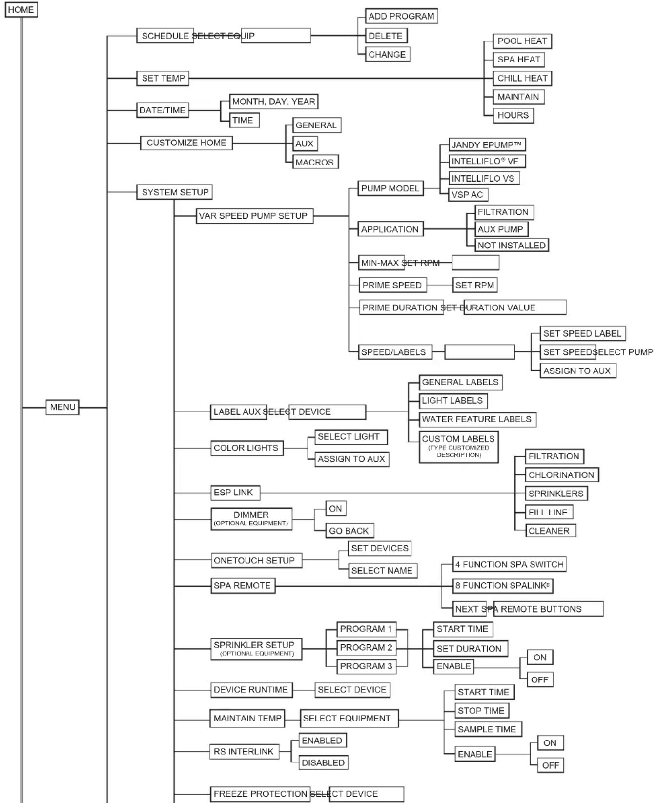
flowchart
graph TD
    A["HOME"] --> B["SCHEDULE SELECT EQUIP"]
    B --> C["ADD PROGRAM DELETE CHANGE"]
    B --> D["POOL HEAT SPA HEAT CHILL HEAT MAINTAIN HOURS"]
    A --> E["SET TEMP"]
    E --> F["MONTH, DAY, YEAR TIME"]
    F --> G["GENERAL AUX MACROS"]
    A --> H["CUSTOMIZE HOME"]
    H --> I["SYSTEM SETUP"]
    I --> J["VAR SPEED PUMP SETUP"]
    J --> K["PUMP MODEL APPLICATION MIN-MAX SET RPM PRIME SPEED PRIME DURATION SET DURATION VALUE SPEED/LABELS"]
    K --> L["FILTRATION AUX PUMP NOT INSTALLED SET RPM"]
    K --> M["SET SPEED LABEL SET SPEED SELECT PUMP ASSIGN TO AUX"]
    A --> N["LABEL AUX SELECT DEVICE"]
    N --> O["GENERAL LABELS LIGHT LABELS WATER FEATURE LABELS CUSTOM LABELS (TYPE CUSTOMIZED DESCRIPTION)"]
    N --> P["FILTRATION CHLORINATION SPRINKLERS FILL LINE CLEANER"]
    A --> Q["COLOR LIGHTS SELECT LIGHT ASSIGN TO AUX"]
    Q --> R["ESP LINK DIMMER (OPTIONAL EQUIPMENT) ON GO BACK"]
    R --> S["ONETOUCH SETUP SELECT NAME 4 FUNCTION SPA SWITCH 8 FUNCTION SPALINK NEXT SPA REMOTE BUTTONS"]
    A --> T["SPA REMOTE"]
    T --> U["SPRINKLER SETUP (OPTIONAL EQUIPMENT) PROGRAM 1 PROGRAM 2 PROGRAM 3 START TIME SET DURATION ENABLE ON OFF"]
    T --> V["DEVICE RUNTIME SELECT DEVICE MAINTAIN TEMP SELECT EQUIPMENT SAMPLE TIME ON OFF"]
    A --> W["FREEZE PROTECTION SELECT DEVICE"]
Continued on next page
Trademarks used herein are the property of their respective owners.
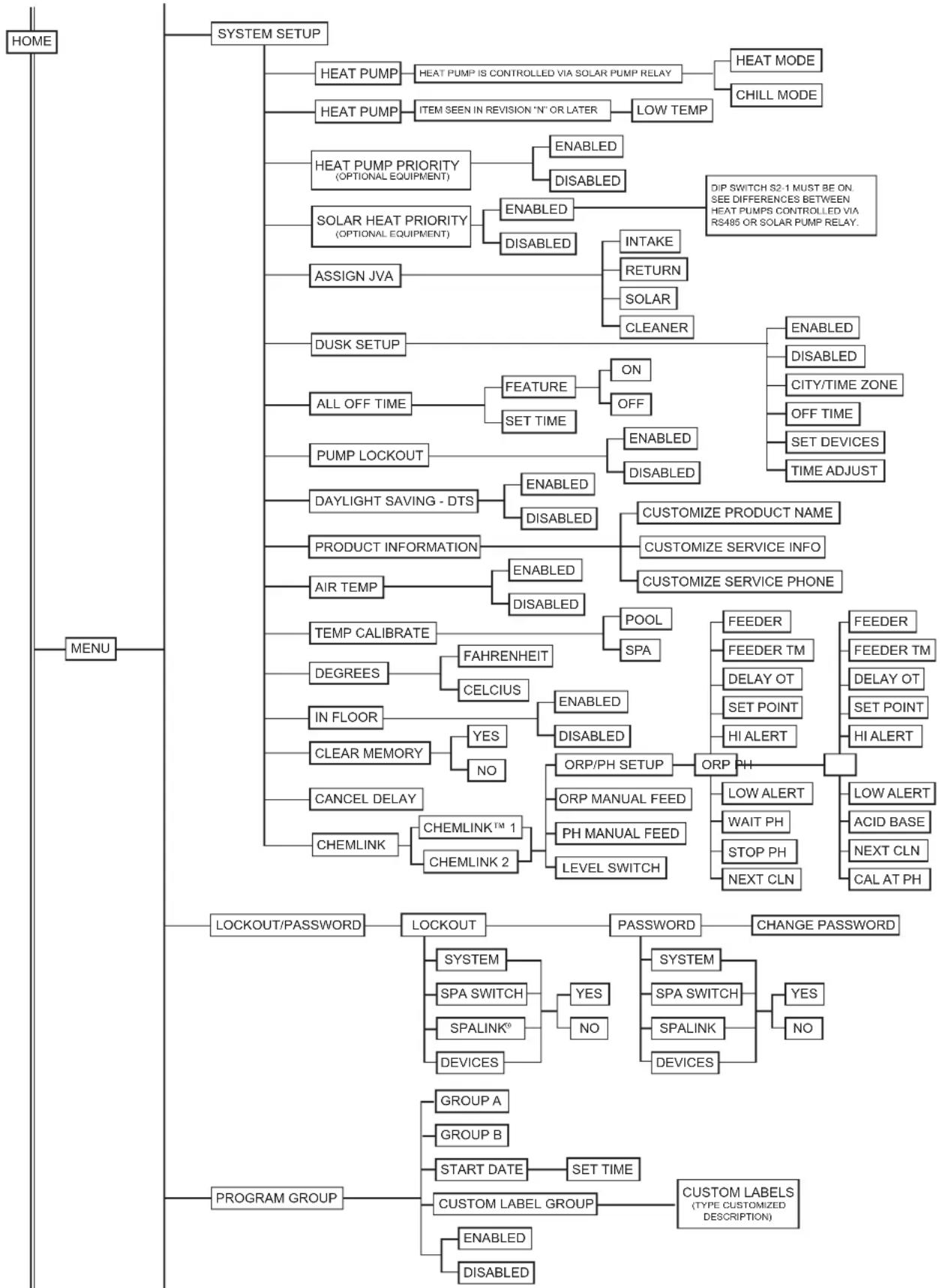
flowchart
graph TD
    A["HOME"] --> B["SYSTEM SETUP"]
    B --> C1["HEAT PUMP"]
    C1 --> D1["HEAT PUMP IS CONTROLLED VIA SOLAR PUMP RELAY"]
    C1 --> D2["HEAT MODE"]
    C1 --> D3["CHILL MODE"]
    B --> C2["HEAT PUMP"]
    C2 --> D4["ITEM SEEN IN REVISION 'N' OR LATER"]
    D4 --> D5["LOW TEMP"]
    B --> C3["HEAT PUMP PRIORITY (OPTIONAL EQUIPMENT)"]
    C3 --> D6["ENABLED"]
    C3 --> D7["DISABLED"]
    D6 --> E1["SOLAR HEAT PRIORITY (OPTIONAL EQUIPMENT)"]
    D6 --> E2["ENABLED"]
    E2 --> F1["INTAKE"]
    E2 --> F2["RETURN"]
    E2 --> F3["SOLAR"]
    E2 --> F4["CLEANER"]
    B --> G1["ASSIGN JVA"]
    G1 --> H1["DUSK SETUP"]
    H1 --> I1["FEATURE"]
    I1 --> J1["ON"]
    I1 --> J2["OFF"]
    I1 --> J3["SET TIME"]
    I1 --> J4["ENABLED"]
    J4 --> K1["DISABLED"]
    K1 --> K2["DISABLED"]
    K2 --> K3["CONTROLIZE PRODUCT NAME"]
    K2 --> K4["CUSTOMIZE SERVICE INFO"]
    K2 --> K5["CUSTOMIZE SERVICE PHONE"]
    B --> G2["PUMP LOCKOUT"]
    G2 --> H2["ENABLED"]
    G2 --> H3["DISABLED"]
    H2 --> I3["ENABLED"]
    H3 --> I4["DISABLED"]
    I3 --> I5["PRODUCT INFORMATION"]
    I5 --> J5["ENABLED"]
    I5 --> J6["DISABLED"]
    J5 --> J7["TEMP CALIBRATE"]
    J7 --> K7["POOL"]
    K7 --> K8["SPA"]
    K8 --> K9["FEEDER"]
    K8 --> K10["FEEDER TM"]
    K8 --> K11["DELAY OT"]
    K8 --> K12["SET POINT"]
    K8 --> K13["HI ALERT"]
    B --> L1["IN FLOOR"]
    L1 --> M1["YES"]
    L1 --> M2["NO"]
    M1 --> N1["ORP/PH SETUP"]
    N1 --> O1["ORP PH"]
    O1 --> P1["LOW ALERT"]
    O1 --> P2["WAIT PH"]
    O1 --> P3["STOP PH"]
    O1 --> P4["NEXT CLN"]
    P4 --> Q1
    P4 --> Q2
    P4 --> Q3["LACKOUT/PASSWORD"]
    Q3 --> R1["LOCKOUT"]
    R1 --> S1["SYSTEM"]
    S1 --> T1["SPA SWITCH"]
    T1 --> U1["YES"]
    T1 --> U2["NO"]
    U2 --> V1["SPALINK®"]
    V1 --> W1["DEVICE SLPAS SWITCH"]
    W1 --> X1["DEVICE SLPALINK®"]
    X1 --> Y1["DEVICE SLPALINK®"]

    B --> Z["PROGRAM GROUP"]
    Z --> AA["GROUP A"]
    Z --> AB["GROUP B"]
    Z --> AC["START DATE"]
    AC --> AD["SET TIME"]
    AD --> AE["CUSTOM LABEL GROUP"]
    AE --> AF["CUSTOM LABELS (TYPE CUSTOMIZED DESCRIPTION)"]

    style A fill:#f9f,stroke:#333
Continued on next page
Trademarks used herein are the property of their respective owners.
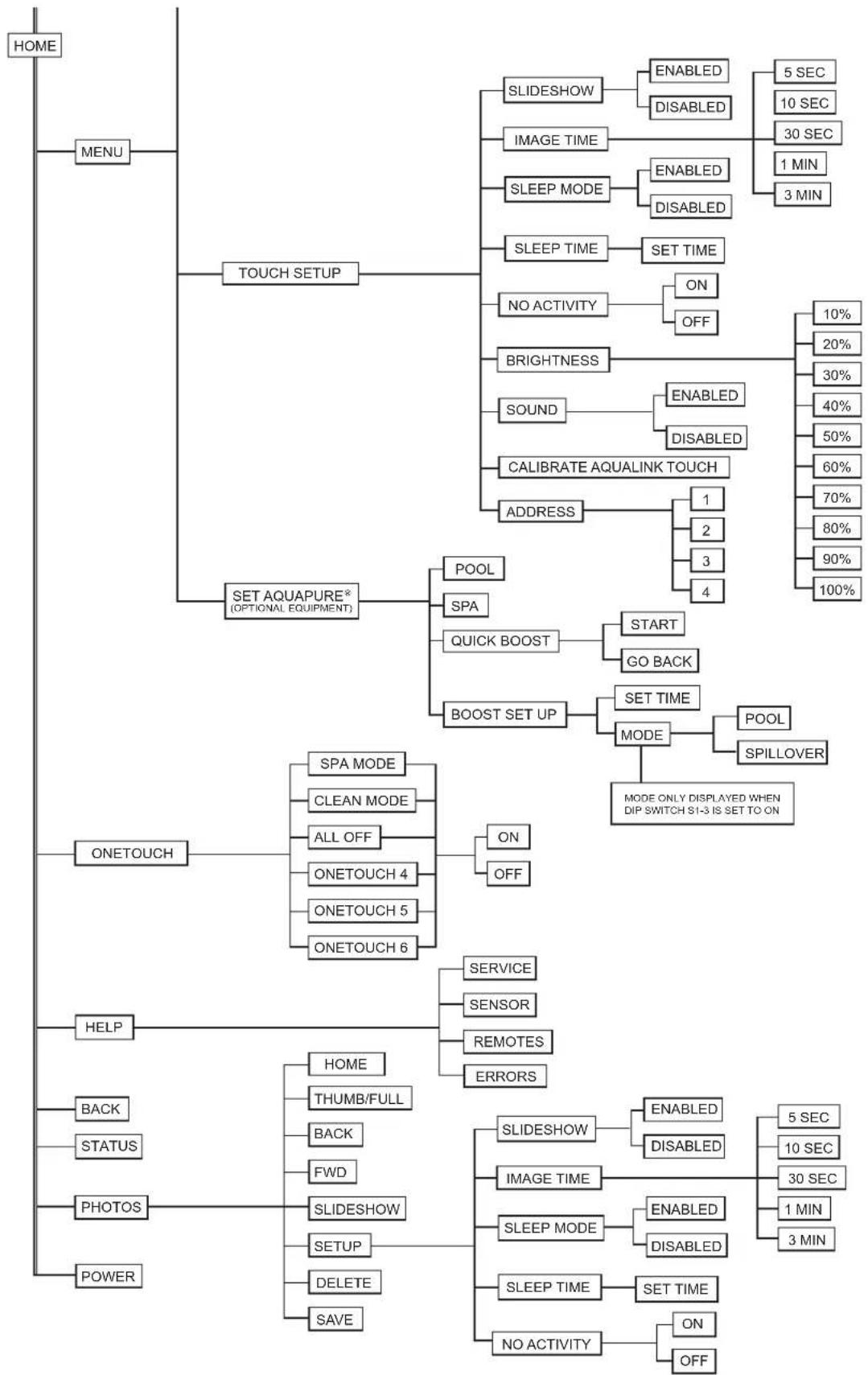
flowchart
graph TD
    A["HOME"] --> B["MENU"]
    B --> C["TOUCH SETUP"]
    C --> D["SLIDESHOW"]
    D --> E["ENABLED"]
    D --> F["DISABLED"]
    E --> G["5 SEC"]
    E --> H["10 SEC"]
    E --> I["30 SEC"]
    I --> J["1 MIN"]
    I --> K["3 MIN"]
    C --> L["IMAGE TIME"]
    L --> M["ENABLED"]
    L --> N["DISABLED"]
    C --> O["SLEEP MODE"]
    O --> P["ENABLED"]
    O --> Q["DISABLED"]
    C --> R["SLEEP TIME"]
    R --> S["SET TIME"]
    R --> T["NO ACTIVITY"]
    T --> U["ON"]
    T --> V["OFF"]
    C --> W["BRIGHTNESS"]
    W --> X["ENABLED"]
    W --> Y["DISABLED"]
    C --> Z["SOUND"]
    Z --> AA["ENABLED"]
    Z --> AB["DISABLED"]
    C --> AC["CALIBRATE AQUALINK TOUCH"]
    AC --> AD["ADDRESS"]
    AD --> AE["1"]
    AD --> AF["2"]
    AD --> AG["3"]
    AD --> AH["4"]
    C --> AI["SET AQUAPURE* (OPTIONAL EQUIPMENT)"]
    AI --> AJ["POOL"]
    AI --> AK["SPA"]
    AI --> AL["QUICK BOOST"]
    AI --> AM["BOOST SET UP"]
    AM --> AN["START"]
    AM --> AO["GO BACK"]
    AM --> AP["SET TIME"]
    AP --> AQ["MODE"]
    AQ --> AR["POOL"]
    AQ --> AS["SPILLOVER"]
    AP --> AT["MODE ONLY DISPLAYED WHEN DIP SWITCH S1-3 IS SET TO ON"]
    C --> AU["ONETOUCH"]
    AU --> AV["SPA MODE"]
    AV --> AW["CLEAN MODE"]
    AV --> AX["ALL OFF"]
    AX --> AY["ONETOUCH 4"]
    AX --> AZ["ONETOUCH 5"]
    AX --> BA["ONETOUCH 6"]
    AU --> BB["ON"]
    AU --> BC["OFF"]
    C --> BD["HELP"]
    BD --> BE["SERVICE"]
    BE --> BF["SENSOR"]
    BE --> BG["REMOTES"]
    BE --> BH["ERRORS"]
    BD --> BI["HOME"]
    BI --> BJ["THUMB/FULL"]
    BI --> BK["BACK"]
    BI --> BL["FWD"]
    BI --> BM["SLIDESHOW"]
    BM --> BN["SETUP"]
    BN --> BO["DELETE"]
    BN --> BP["SAVE"]
    BD --> BQ["BACK"]
    BQ --> BR["STATUS"]
    BD --> BS["PHOTOS"]
    BS --> BT["POWER"]

    subgraph Details
        D
        E
        F
        G
        H
        I
        J
        K
        L
        M
        N
        O
        P
        Q
        R
        S
        T
        U
        V
        W
        X
        Y
        Z
        AA
        AB
        AC
        AD
        AE
        AF
        AG
        AH
        AI
        AJ
        AK
        AL
        AM
        AN
        AO
        AP
        AQ
        AR
        AS
        AT
        AU
        AV
        AW
        BX
        BY
        CA
        DB
        BE
        BF
        BG
        BH
        BI
        BJ
        BK
        BL
        BM
        BN
        BO
        BP
        BP
        BH
        BI
        BJ
        BK
        BJ
        BI
        BJ
        BJ
        BI
        BJ
        BJ
        BI
        BJ
        BI
        BI
        BI
        BI
        BI
        BI
        BI
        BI
        BI
        BI
        BI
        BI
        BI
        BI
        BI
        BI
        BI
        BI
        BI
        BI
        BI
        BI
    end

    C --> D & E & F & G & H & I & J & K & L & M & N & O & P & Q & R & S & T & U & V & W & X & Y & Z & A & B & C & D & E & F & G & H & I & J & K & L & M & N & O & P & Q & R & S & T & U & V & W & X & Y & Z & A & B & C & D & E & F & G & H & I & J & K & L & M & N & O & P & Q & R & S & T & U & V & W & X & Y & Z & A \\n
Trademarks used herein are the property of their respective owners.
NOTES
Jandy®

CONFORMS TO ANSI/UL STD. 60950-1 CERTIFIED TO CAN/CSA STD. C22.2 NO. 60950-1
Zodiac Pool Systems, Inc.
6000 Condor Drive • Moorpark, CA USA 93021 • 800.822.7933 • Fax 877.327.4103
Litho in U.S.A. © Zodiac Pool Systems, Inc. 1001
- AquaLink® Touch™
- WARNING
- ATTENTION
- Table of Contents
- Section 1. Important Safety Instructions ..... 6
- Section 2. Overview of the AquaLink Touch Controller....8
- Section 3. Using the Home Screen Menu .. 10
- Section 4. Using the Menu Screen .....11
- Section 5. Using the OneTouch Menu ..... 22
- Section 6. Using the Help Menu.... 23
- Section 7. Using the Status Menu ...... 24
- Section 8. Using the Photos Menu ...... 25
- Section 9. Using Other Devices ON/OFF ... 27
- Section 10. System Setup .... 32
- Section 11. Heat Pump Setup .... 44
- Section 12. Variable Speed Pump Setup ..... 47
- Section 13. Sprinkler System Setup .... 52
- Section 14. ChemLink™ Setup .... 55
- EQUIPMENT INFORMATION RECORD
- Section 1. Important Safety Instructions
- READ AND FOLLOW ALL INSTRUCTIONS Lire la notice technique.
- DANGER
- To Reduce the Risk of Injury -
- AVERTISSEMENT
- CAUTION
- Section 2. Overview of the AquaLink Touch Controller
- System Overview
- Basic Functions
- Turning ON the AquaLink Touch
- Turning OFF the AquaLink Touch
- Battery Status for Wireless Controller
- Signal Strength for Wireless Controller
- Maintenance Information
- Section 3. Using the Home Screen Menu
- Home Screen
- Title Bar
- Middle Info Panel
- Navigation Bar
- Dialog Boxes
- INFORMATION
- Section 4. Using the Menu Screen
- Menu Screen
- To Display the Menu Screen
- Schedule
- Adding Devices to the Circuit List
- First Step - Selecting the new device
- MENU > SCHEDULE > SCHEDULE DEVICES
- Second Step - Programming the new device
- ON/OFF Times
- MENU > SCHEDULE
- Set Temperature (For Pool and Spa Only System)
- Pool Heat
- Spa Heat
- Chiller
- To Set Up Date/Time
- Date
- MENU > SET DATE/TIME
- Time
- Customize Home
- MENU > CUSTOMIZE HOME
- Customize General, Aux and OneTouch Items
- Lockouts Password
- To Lock Out Devices
- MENU > LOCKOUTS PASSWORD
- To Set Lockout Password
- How to Use the System when a Password is Enabled
- AquaPure®
- MENU > SET AQUAPURE > SET CHLORINE PRODUCTION
- To Set Up Pool/Spa
- To Set Up Quick Boost
- To Pause, Restart and Stop Quick Boost
- Boost Setup
- Touch Setup
- MENU > TOUCH SETUP
- Brightness
- Sound
- Calibrate the AquaLink Touch
- Address
- RF Channel (For wireless units only)
- AquaLink Touch J-Box LED Operation
- Program Group
- MENU > PROGRAM GROUP
- A and B Groups
- Program Auto Switch
- Custom Label Group
- Custom Label
- Using the Alpha Keyboard
- Using the Numeric Keyboard
- 1 2 3 ←
- Section 5. Using the OneTouch Menu
- OneTouch
- Spa Mode
- All Off
- Section 6. Using the Help Menu
- Help Menu
- MENU > HELP
- Help Sensors
- MENU > HELP > HELP SENSORS
- Help Remotes
- Help Errors
- Section 7. Using the Status Menu
- Status Menu
- Section 8. Using the Photos Menu
- Creating a Slideshow
- Inserting a memory card
- Importing and Deleting Digital Photos
- Slideshow Setup
- To Enable Slideshow
- HOME > PHOTOS > SETUP > SLIDESHOW ENABLED/ DISABLED
- Image Time
- HOME > PHOTOS > SETUP > IMAGE TIME
- Sleep Mode and Sleep Time
- PHOTOS > SETUP > SLEEP MODE
- PHOTOS > SETUP > SET TIME
- No Activity
- PHOTOS > SETUP > NO ACTIVITY
- Section 9. Using Other Devices ON/OFF
- Using Other Devices On/Off
- HOME > OTHER DEVICES ON/OFF
- Filter Pump
- HOME > OTHER DEVICES ON / OFF > FILTER PUMP
- Spa
- Pool Heat
- Spa Heat (Dual Equipment)
- Solar Heat
- Auxiliary Equipment
- HOME > DEVICES > AUX3
- Using Color Lights
- HOME > OTHER DEVICES ON/OFF > AUX1 > SET COLORS
- IMPORTANT Information
- TEMP1 / TEMP2 (Pool or Spa Only)
- To Set Up TEMP1
- To Set Up TEMP2 (For Pool and Spa Only System)
- Two Speed Operation (\*Not Available for Export Models\*)
- Two Speed Manual Operation
- - For Pool and Spa Combination Units
- - For Pool or Spa Only Units
- • For Dual Equipment Units
- - Two Speed Programming for All Units
- High Speed Filtration Pump
- Low Speed Filtration Pump
- Section 10. System Setup
- System Setup Screen
- To Access System Setup
- MENU > SYSTEM SETUP
- Label Auxiliary Functions
- To Set Up Label Auxiliary
- MENU > SYSTEM SETUP > LABEL AUX
- Color Lights
- To Set Up Color Lights
- ESP Link (Seasonal Adjust)
- To Set Up Seasonal Adjust
- MENU > SYSTEM SETUP > ESP LINK > SEASONAL ADJ
- ESP Link Operation
- Set Dimmers
- To Set Dimmers
- MENU > SYSTEM SETUP > DIMMERS
- OneTouch
- MENU > SYSTEM SETUP > ONETOUCH SETUP
- Select Devices
- Select Name
- Spa Remotes
- MENU > SYSTEM SETUP > SPA REMOTES
- Spa Side Switch
- SpaLink® Setup
- Device Runtime
- To Set Up Device Runtime
- MENU > SYSTEM SETUP > DEVICE RUNTIME
- Maintain Temp
- To Set Up Maintain Temp
- MENU > SYSTEM SETUP > MAINTAIN TEMP
- RS InterLink
- To Set Up RS Intelink
- MENU > SYSTEM SETUP > RS INTERLINK
- Freeze Protection
- To Set Up Freeze Protection
- MENU > SYSTEM SETUP > FREEZE PROTECT
- Important Information on Freeze Protection
- Assign JVAs
- To Set Up Assign JVs
- Dusk Setup
- MENU > SYSTEM SETUP > DUSK SETUP
- Dusk Setup Off Time
- City/Time Zone
- Assign Devices
- All Off Time
- To Set Up All Off Time
- Pump Lockout
- To Set Up Pump Lockout
- Daylight Savings Time (DST)
- To Set Up DST
- Product Information
- Customize Product and Service Info
- Customize Service Phone
- SYSTEM SETUP > PRODUCT INFO
- Air Temperature
- To Set Up Air Temperature
- MENU > SYSTEM SETUP > AIR TEMP
- Temp Calibration
- To Set Up Calibration
- MENU > SYSTEM SETUP > TEMP CALIBRATE
- Degrees C/F
- To Set Up Degrees
- MENU > SYSTEM SETUP > DEGREES
- In-Floor Cleaning
- To Set Up In Floor Cleaning
- MENU > SYSTEM SETUP > IN-FLOOR
- Clear Memory
- To Set Up Clear Memory
- MENU > SYSTEM SETUP > CLEAR MEMORY
- Cancel Delay
- Section 11. Heat Pump Setup
- Solar Priority/Heat Pump Priority
- Heat Pump (Heat Mode)
- Heat Pumps Controlled by Extra Aux/Solar Boost Relay
- Heat Pumps Controlled by the RS485 Interface
- Heat Mode
- MENU > SYSTEM SETUP > HEAT PUMP
- Heat Pump (Chiller Mode)
- Heat Pumps (Chiller) Controlled by the Extra Aux/Solar Boost Relay
- IMPORTANT Information on Chiller
- Heat Pumps (Chiller) Controlled by the RS485 Interface
- Chill Mode
- Section 12. Variable Speed Pump Setup
- Example:
- To Select the Pump/Model
- MENU > SYSTEM SETUP > VSP SETUP
- To Set Up the Pump Application
- To Set Up MIN/MAX Parameters
- To Set Up the Priming Speed
- To Set Up the Priming Duration Time
- To Assign a Pump Speed to an AUX
- To Set Up Pump Speed
- To Re-label the Speed Preset
- Default Preset Speed Labels (RS Combo and RS only)
- Preset 1:
- Preset 2:
- Preset 3:
- Preset 4:
- Preset 5:
- Preset 6:
- Preset 7:
- Preset 8:
- Default Preset Speed Labels (Dual Equipment)
- Section 13. Sprinkler System Setup
- Running the Sprinkler System
- Cancel Today - 24 Hour Sprinkler Delay
- OTHER DEVICES ON / OFF > SPRINKLERS > CANCEL TODAY
- Enabling the Sprinkler System
- OTHER DEVICES ON/OFF > SPRINKLERS > PROGRAMS
- Manually Starting a Sprinkler Program
- Disabling the Sprinkler System
- Programming Sprinkler System
- MENU > SYSTEM SETUP > SPRINKLER SETUP
- To Set Up the Water Days
- To Set Up the Sprinklers Program Start Time menu
- To Set Up the Sprinkler Valve Duration Time
- Section 14. ChemLink™ Setup
- To Set Up the ChemLink
- SYSTEM SETUP > SET CHEMLINK > CHEMLINK
- To Configure the ORP Controller
- ORP Feeder Type
- ORP Feeder Times
- ORP Delay On Time
- ORP Setpoint
- ORP Alarm - High Alert
- ORP Alarm - Low Alert
- Wait or Stop pH
- ORP Next Cleaning
- To Configure the pH Controller
- pH Feeder Type
- pH Feeder Times
- pH Delay On Time
- pH Setpoint
- pH Alarm - High Alert
- pH Alarm - Low Alert
- pH Acid or Base Feed
- pH Next Cleaning
- pH Next Calibration
- pH Calibration
- Manual Feed Activation
- To Perform an ORP Manual Feed
- To Perform a pH Manual Feed
- To Enable the ChemLink™ Feeder Tank Level Switch
- Section 15. Glossaries
- Safety Delays and Lockouts
- Lockouts
- Pool/Spa Switching Filter Pump Delay
- Heater Cool Down Delay
- Heater Start-up
- Heater "Short Cycling" Prevention
- Cleaner Lockout
- Spillover Lockout
- Spillover
- Enabled
- Disabled
- Special Auxiliary Labels
- Spare AUX
- Extra AUX
- Air Blower
- Fill Line
- Controller Messages
- CLEANER CANNOT BE TURNED ON WHILE SPA IS ON
- CLEANER CANNOT BE TURNED ON WHILE SPILLOVER IS ON-
- FREEZE PROTECT
- SENSOR OPEN
- POOL HEATER ENABLED
- SERVICE MODE
- SENSOR SHORT
- SPA WILL TURN OFF AFTER COOL DOWN CYCLE
- TIMED AUX ON, WILL TURN OFF AFTER 30 MINUTES
- TIMEOUT MODE
- SPILLOVER DISABLED WHILE SPA IS ON
- NOTES
Brand : Jandy
Model : AquaLink Touch
Category : Home Automation