
LVC-IV - Controller Draper - Free user manual and instructions
Find the device manual for free LVC-IV Draper in PDF.


| Brand | Draper |
| Model | LVC-IV |
| Product Type | Controller |
| Number of Channels | 4 |
| Power Supply | 24V DC (low voltage) |
| Dimensions (H x W x D) | 120 mm x 70 mm x 30 mm |
| Weight | 0.2 kg |
| Control Interface | Dry contact, momentary switches |
| Output Type | Relays (SPST) |
| Maximum Load per Channel | 2A at 24V DC |
| Wireless Protocol | None (wired only) |
| Enclosure Material | ABS plastic |
| Color | White |
| LED Indicators | Power and channel status |
| Compatible Devices | Draper motorized shades and screens |
| Mounting | Wall mount via included bracket |
| Operating Temperature | 0°C to 40°C |
| Certification | CE, RoHS |
| Warranty | 2 years |
| Package Contents | Controller, mounting bracket, screws, manual |
Frequently Asked Questions - LVC-IV Draper
User questions about LVC-IV Draper
0 question about this device. Answer the ones you know or ask your own.
Ask a new question about this device
Download the instructions for your Controller in PDF format for free! Find your manual LVC-IV - Draper and take your electronic device back in hand. On this page are published all the documents necessary for the use of your device. LVC-IV by Draper.
USER MANUAL LVC-IV Draper
Please Note
-Don't let the RF receiver touch metal objects; this could affect the maximum distance the transmitter can be from the RF receiver.
-Disconnect the power supply before installing the RF receiver.
-Avoid electrostatic interference: Static electricity will damage the electronic components.
-Make sure there is more than 5 feet (1.52 meters) between the RF receiver and ground.
-Make sure there is more than 1 foot (30.5cm) between the RF receiver and ceiling.
-Make sure there is more than 1 foot (30.5cm) between the RF receiver and transmitter.
-If using more than one receiver, make sure they are separated by more than 8" (20cm).
If you encounter any difficulties installing or servicing your LVC-IV, call your dealer or contact Draper, Inc.
Radio Frequency (RF) Remote Control
The LVC-IV comes with built-in Radio Frequency Remote control capability (optional handheld transmitter NOT included).
To "Learn" a remote
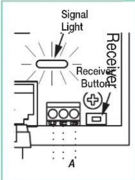
- Press receiver button on LVC-IV (see Fig. 2A).
- Signal light will flash slowly.
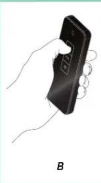
- Press transmitter's Up button within 10 seconds (see Fig. 2B).
- Signal light flashes three times quickly.
To "Un-Learn" a remote
- Press receiver button on LVC-IV (see Fig. 2A).
- Signal light will flash slowly.
- Press transmitter's Down button within 10 seconds (see Fig. 2C).
- Signal light flashes three times quickly.
natural_image
Illustration of a hand holding a black handheld device with a curved handle, labeled 'B' below (no text or symbols on the device itself)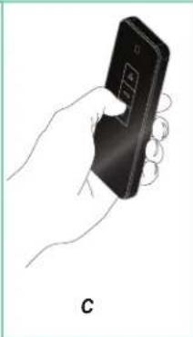
natural_image
Hand holding a smartphone with a control panel, labeled 'C' at the bottom (no text or symbols on the device itself)To "Un-Learn" all remotes
Figure 2
- Press receiver button on LVC-IV until signal light flashes quickly, then release.
- Press receiver button once while signal light is flashing.
- Signal light will stop flashing.
Please Note: Operating range is 250ft (76 meters) open distance. RF Signal will degrade significantly with each wall it is required to penetrate. If you are experiencing issues with RF signal strength, the RF antenna can be threaded out one of the knockouts for better reception.
InfraRed (IR) Remote Control
- Plug Optional IR Eye into mini plug input provided on LVC-IV (see Figs. 1 and 3).
- IR Remote Control transmitter does not need to be "learned" by the LVC-IV. Simply point and operate.
- Maximum IR Eye cable length is 42" (106 cm).
Please Note: IR Transmitter Range is 26ft. (7.9 metera).

natural_image
Line drawing of a U-shaped heating element with a plug and connector, labeled Figure 3 (no text or symbols on the diagram itself)Figure 3
DC Low Voltage Trigger
The LVC-IV comes with built-in connection for sending a DC trigger (4-28 VDC) from the projector to the projection screen.
- Connect remote trigger voltage from projector to the low voltage trigger cable.
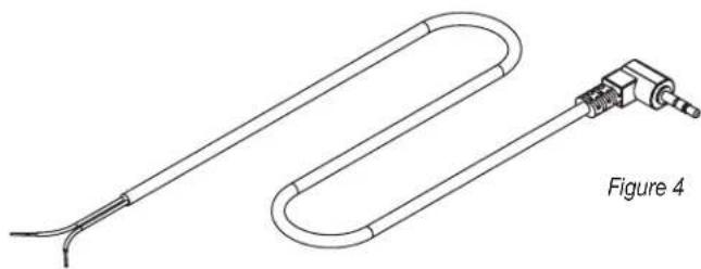
- Plug the mini-jack plug of the low voltage trigger cable to the LVC-IV (Figure 1 & 4).
- When projector is 'ON' the low voltage output of the projector will cause LVC-IV to deploy projection screen. When projector 'OFF' the low voltage is removed from LVC-IV and projection screen will retract into case.
natural_image
Line drawing of a U-shaped tube with a connector, labeled Figure 4 (no text or symbols on the diagram itself)External LVC-IV—Single or Multiple
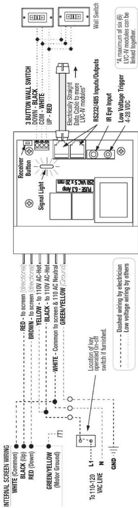
Projection Screen Wiring Diagram
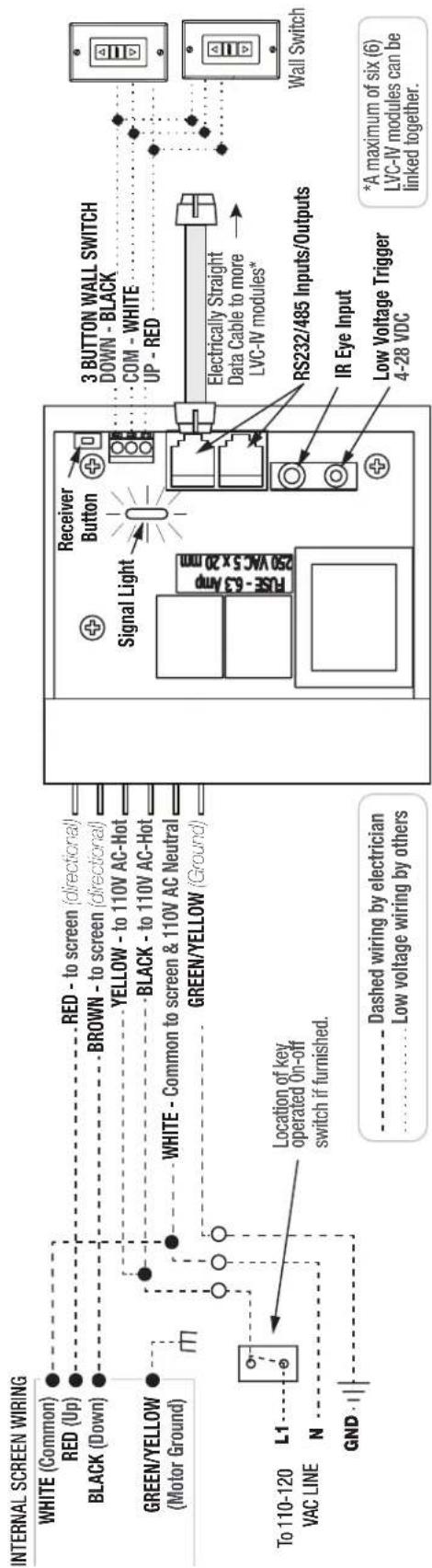
External LVC-IV—Single or Multiple
Wiring Diagram for Ambassador and Rolleramic
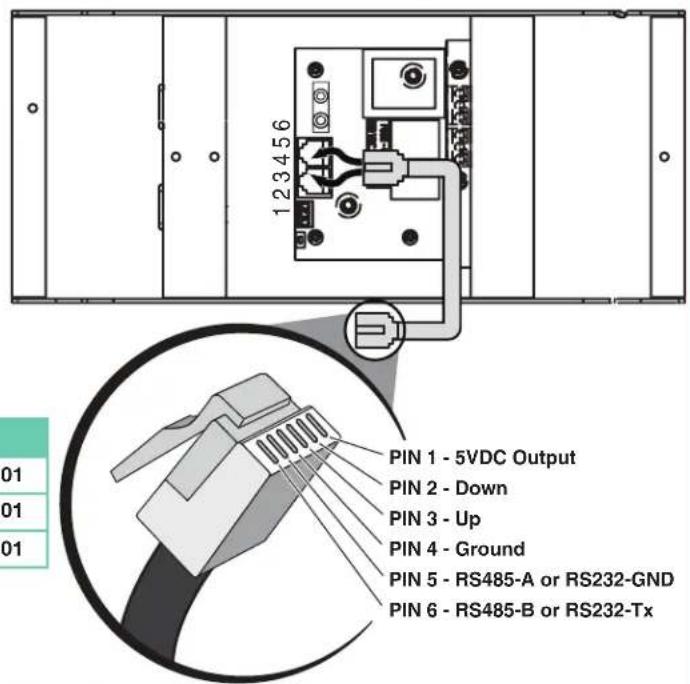
RS232 / RS485 Information
RS232 / RS485 CommPort Parameters:
- Frequency (BAUD Rate): 2400
- Data long code : 8
- Parity Check : N
- Start bit : 1
- Stop bit : 1
- Flow Control : NONE
Please Note:
Connections using modular cable must be made using electrically straight 6-conductor modular cable (RJ25). This means colors do not cross over: blue leads to blue, green to green, etc. (see diagram at right)
| COMMAND COMMAND STRINGS | REMARK | |
| UP 9A 01 | 01 00 0A DD D7 | ID No.: 1 / Channel: 01 |
| STOP 9A 01 | 01 00 0A CC C6 | ID No.: 1 / Channel: 01 |
| DOWN 9A 01 | 01 00 0A EE E4 | ID No.: 1 / Channel: 01 |
For more detailed programming instructions or group control go to: http://www.draperinc.com/DraperPro (registration required)
LVC-IV Dimensions
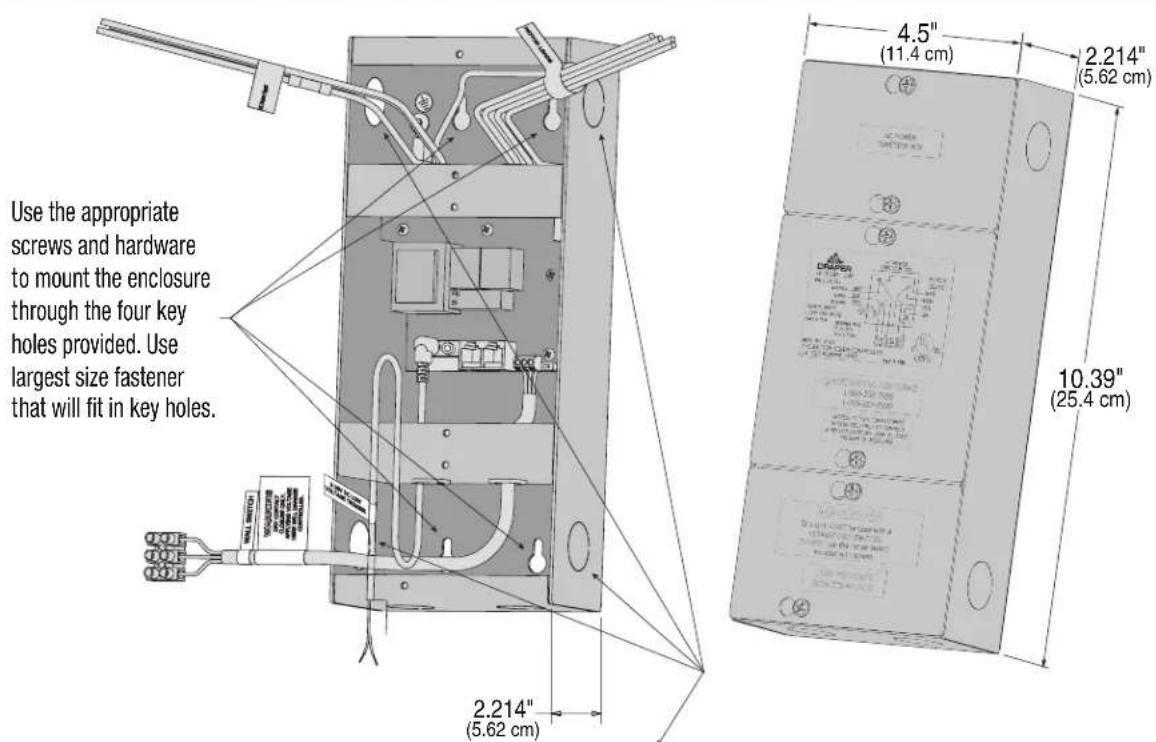
For AC supply wires attach appropriate 12 " (13mm) Trade Size connector to route wiring through knockouts. For low voltage wires attach with appropriate connector to route wiring through knockouts. Knockouts are provided on all four sides of the enclosure.
Brand : Draper
Model : LVC-IV
Category : Controller