72350 - Cables for Computers and Peripherals iPort - Free user manual and instructions
Find the device manual for free 72350 iPort in PDF.


| Product Type | Computer Cable |
| Length | 1.8 m (6 ft) |
| Connector Type A | HDMI Type A Male |
| Connector Type B | HDMI Type A Male |
| HDMI Version | 2.0 |
| Maximum Resolution | 4K @ 60 Hz |
| Data Transfer Speed | 18 Gbps |
| Audio Return Channel (ARC) | Yes |
| Ethernet Channel | Yes (HEC) |
| Shielding | Triple shielding (foil + braid + drain wire) |
| Jacket Material | PVC |
| Connector Plating | Gold-plated contacts |
| Compatible Devices | Computers, monitors, projectors, HDTV, gaming consoles |
| Warranty | 2 years |
| Operating Temperature | -20°C to 60°C |
| Weight | Approx. 100 g |
| Color | Black |
| Package Includes | 1 x HDMI cable |
Frequently Asked Questions - 72350 iPort
User questions about 72350 iPort
0 question about this device. Answer the ones you know or ask your own.
Ask a new question about this device
Download the instructions for your Cables for Computers and Peripherals in PDF format for free! Find your manual 72350 - iPort and take your electronic device back in hand. On this page are published all the documents necessary for the use of your device. 72350 by iPort.
USER MANUAL 72350 iPort
Thank you for purchasing the all new IPORT CONNECT Platform. We hope you enjoy this revolutionary new system and if at any time you need more assistance please contact IPORT Tech Support via Online chart or through our help desk.
- IPORT Team
Whats in box:
1 - IPORT CONNECT WallStation
1 - IPORT Security tool - 1.5mm hex key
1 - Info Card
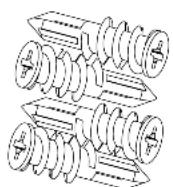
4 - Drwyall Anchors
4 - #6 HighLow thread Screws
1 - RJ45 - DC Connector
1 - RJ45 - TE Connector
1 - Phoenix - DC Connector
1 - Phoenix - TE Connector
1 - 24V DC 1.5A Power Supply
Product Info Page - www.iportproducts.com/cpwallstation
Glossary of Terms:
- WallStation - The fully assembled CONNECT PRO Station holding and charging the IPORT CONNECT Case.
- Cover Plate - The removeable plastic cover that attaches to the WallStation, covering the label and Screws.
- IPORT Security Tool - The orange handled 1.5mm hex tool used for locking and unlocking IPORT Products.
WALLSTATION
WALLSTATION INSTALL OPTIONS
Before starting, detimine the install scenario that best describes your desired install. Then click on the title to be directed to the appropriate install steps.
New Construction using Cat 6 Cable | pg. 4
Existing Construction using Cat 6 Cable | pg. 15
Upgrading a LAUNCH WallStation | pg. 25
New Construction using 14-2 Wire | pg. 32
Existing Construction using 14-2 Wire | pg. 45
IPORT CONNECT PRO WallStation Install New Construction - Cat6
Before Construction is complete
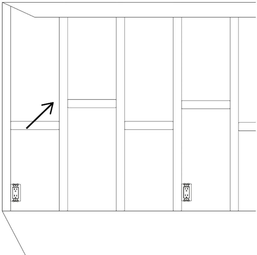
1. Determine the desired location of the IPORT CONNECT PRO WallStation will live when the construction is completed.
natural_image
Line drawing of a cabinet or wardrobe layout with no text, numbers, or symbols2. Install a 1 Gang electrical box or low voltage ring in the desired location of the WallStation.
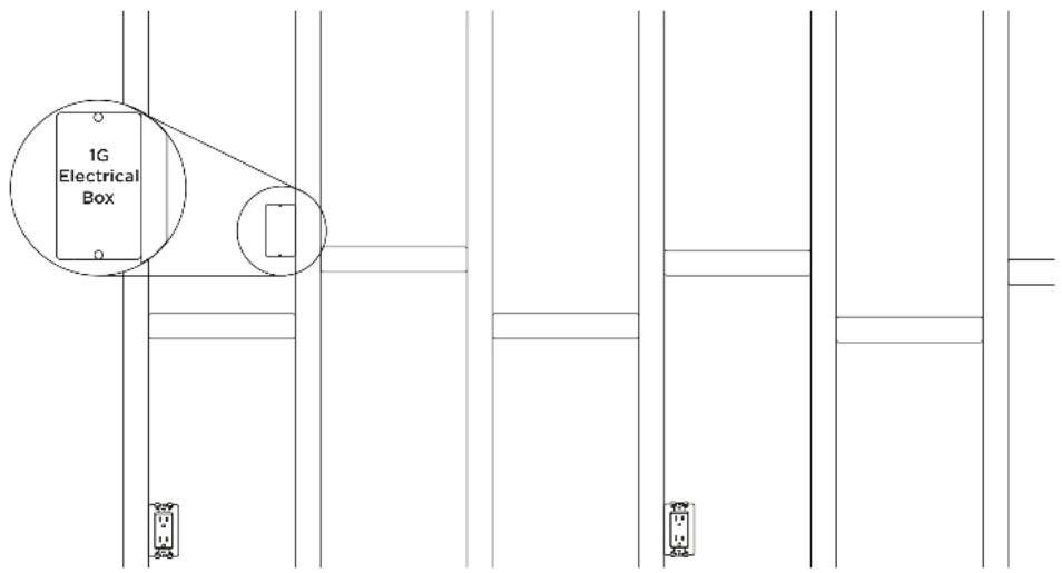
NOTE: The CONNECT PRO WallStation will cover a 1G electrical box only. A 2 Gang electrical box will interfere with the mounting hardware.

natural_image
Technical line drawing of a rectangular enclosure with mounting fixtures and a circular checkmark below (no text or symbols)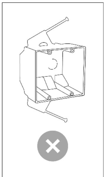
natural_image
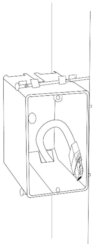
Technical line drawing of a mechanical device with mounting brackets and a cross symbol (no text or labels)- Run a Cat6 cable terminated with an RJ45 Connectors (T568A or T568B) from the WallStation location to a nearby AC outlet, closet, or network rack location and terminate the other end of the cable the same as before.
NOTE: Make sure to secure the Cat6 cable appropriately onto the Electrical box or Low Voltage ring to retrieve at a later time.
natural_image
Technical line drawing of a mechanical component with internal curved structure (no text or symbols)Installing the WallStation After Construction
- Terminate the Cat6 with an RJ45 Connector if not done so previously using T568A or T568B standards.

natural_image
Technical line drawing of a mechanical component with a curved bracket and mounting holes (no text or symbols)- Remove the WallStation, Drywall anchors and Screws from the box and place on a table.

natural_image
Simple diagram of a circular ring with four evenly spaced dots inside, enclosed in a rounded square (no text or symbols)
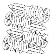
x4
3. Insert the WallStation into the 1G box.
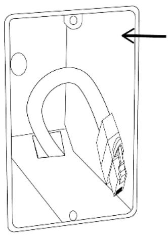
natural_image
Technical line drawing of a mechanical component with an arrow indicating direction (no text or symbols)
natural_image
Technical line drawing of a rectangular electronic device casing with mounting holes and a central circular component (no text or symbols)- Use a leveling tool to level the WallStation and mark the 4 locations for the provided Anchors. Remove the WallStation from the 1G Box.

natural_image
Technical diagram of a mechanical component with circular and rectangular features, no text or symbols present- Screw the 4 provided anchors into the wall where marked.

natural_image
Technical line drawing of a mechanical component with no visible text or symbols- Connect the RJ-45 to TE Connector provided to the Cat6 cable and onto the white TE connector WallStation DC Adapter.
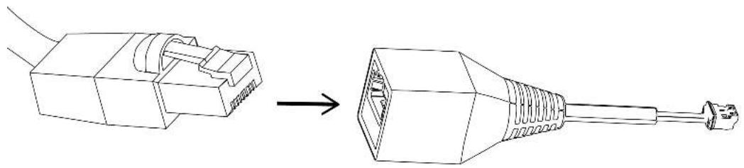
natural_image
Diagram showing a device being processed from an internal component to a final connector (no text or symbols present)Label wire WARNING: Only for DC Low Voltage - Not for PoE

natural_image
Technical line drawing of an electronic device casing with internal components and a rod inserted into it (no text or symbols)Zip tie the Connector to the DC board for added cable retnetion.
7. Insert the WallStation back into the 1G box and use the provided screws to attach the WallStation to the wall.
IMPORTANT: Make Sure to position the WallStation with the Up Arrow facing up. Use a leveling tool to level the WallStation and hand tighten the screws.

natural_image
Technical line drawing of a device front panel with circular center and mounting holes (no text or symbols)- Attach the WallStation Cover Plate over the WallStation making sure to alight the positioning notch with the tooth on the WallStation.
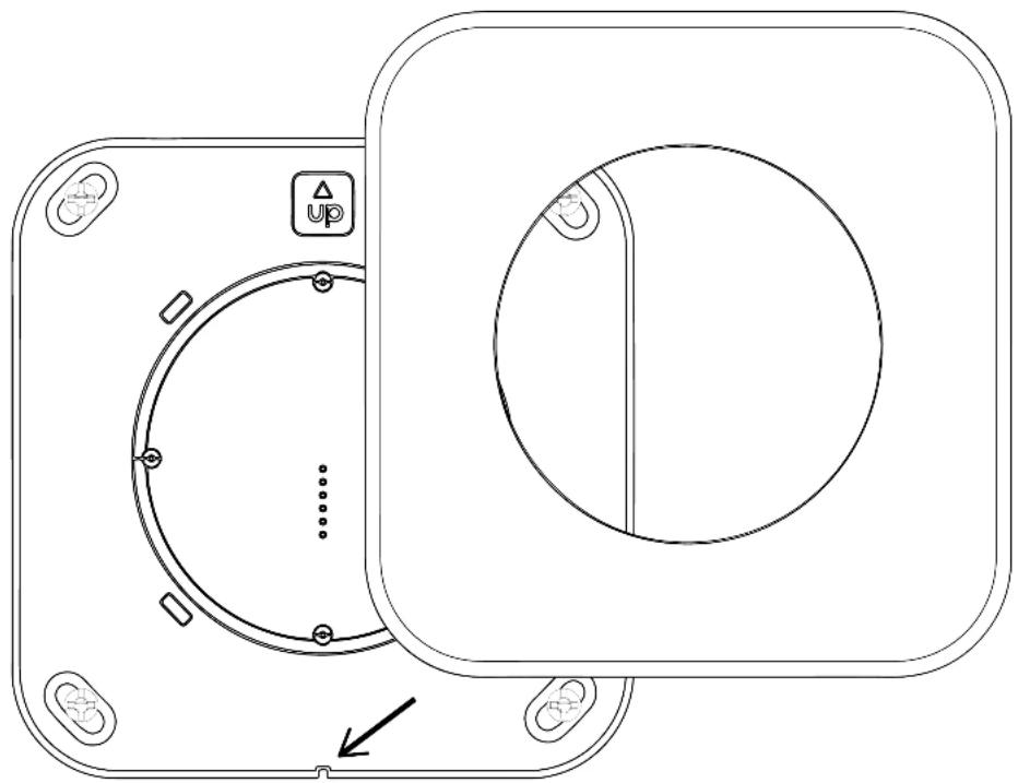
natural_image
Technical line drawing of a device casing with circular components and mounting holes (no text or symbols)
natural_image
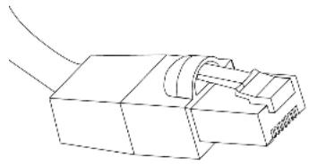
Simple circular diagram with four evenly spaced dots and a central dot, enclosed in a rounded square border (no text or symbols)- Connect the RJ-45 to DC Connector at the other end of the Cat6 Cable.
natural_image
Line drawing of a USB connector (no text or symbols)
natural_image
Line drawing of a USB connector with port and cable (no text or symbols)- Connect the provided DC power adapter into the other end of the RJ-45 DC adapter and plug in the power adapter into an AC outlet.

natural_image
Line drawing of two electrical connectors with wires, one showing a switch and the other a plug (no text or symbols)Grommit not included
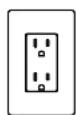
For a clean finished look place the Connector and DC barrel plug back through the grommit into the wall.

- Place a Case with an iPad installed onto the WallStation to determine power was installed properly and the iPad charges.

natural_image
Line drawing of a tablet device with a circular screen and an attached rectangular frame, showing no text or symbols.Installing the WallStation in Existing Construction - Cat6
- Determine the desired location of the IPORT CONNECT PRO WallStation.

- Use a 2-3/4" (70mm) hole saw to cut a hole in the desired location of the WallStation

- Insert the WallStation into the 2 3/4 - inch hole and use a leveling tool to level the WallStation. Mark the 4 locations for the provided Anchors.

natural_image
Technical diagram of a mechanical component with circular and rectangular features, no text or symbols present- Remove the WallStation form the wall once you have marked the 4 anchor locations.

natural_image
Technical line drawing of a square mechanical component with mounting holes and a circular top, showing no text or symbols.5. Screw the provided anchors into the wall where marked.

natural_image
Technical line drawing of a circular component with four corner features (no text or symbols)- Use the 2 3/4 - inch hole to fish a Cat6 cable to a nearby AC outlet, closet or network rack.

natural_image
Pure technical diagram of a curved pipe or tube with four circular reference points (no text or symbols)
natural_image
Pure electrical circuit lines without any symbols
natural_image
Simple line drawing of a wall socket with two screws and three internal slots (no text or symbols)Grommit not included
7. Terminate both ends the Cat6 with an RJ45 Connector using T568A or T568B standards

natural_image
Pure technical line drawing of a mechanical component without any text, numbers, or symbolsLabel wire WARNING: Only for DC Low Voltage - Not for PoE

natural_image
Pure electrical circuit lines without any symbolsGrommit not included

natural_image
Simple line drawing of a rectangular electrical outlet with four internal slots and two mounting holes (no text or symbols)- Connect the RJ-45 to TE Connector provided to the Cat6 cable and onto the white TE connector WallStation DC Adapter.

natural_image
Diagram showing a device being processed from a cable, with no visible text or symbols
natural_image
Technical line drawing of an electronic device casing with internal components and a rod inserted (no text or symbols)Zip tie the Connector to the DC board for added cable retnetion.
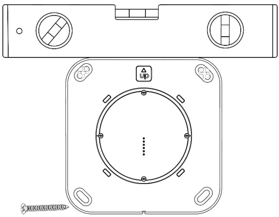
- Insert the WallStation back into the wall and use the provided screws to attach the WallStation to the wall anchors.
IMPORTANT: Make Sure to position the WallStation with the Up Arrow facing up. Use a leveling tool to level the WallStation and hand tighten the screws.
natural_image
Technical line drawing of a device front panel with circular center and mounting holes (no text or symbols)10. Attach the WallStation Cover Plate over the WallStation making sure to alight the positioning notch with the tooth on the WallStation.

natural_image
Technical line drawing of a mechanical component with mounting holes and a circular cutout (no text or symbols)
natural_image
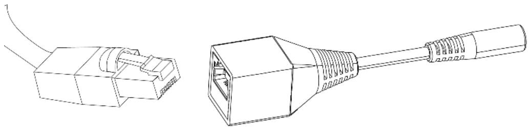
Simple circular diagram with four evenly spaced dots and a central dot, enclosed in a rounded square border (no text or symbols)- Connect the RJ-45 to DC Connector at the other end of the Cat6 Cable.
natural_image
Technical line drawing of two types of electrical connectors: a rectangular connector with cable and a multi-pin connector (no text or symbols present)- Connect the Provided DC Power Adapter into the wall and connect the barrel connector to the other end of the RJ-45-DC adapter.

natural_image
Line drawing of two electrical connectors with wires, one showing a switch and the other a plug (no text or symbols)Grommit not included
WALLSTATION
For a clean finished look place the Connector and DC barrel plug back through the grommit into the wall.

- Place a Case with an iPad installed onto the WallStation to determine power was installed properly and the iPad charges.

natural_image
Line drawing of a tablet device with a circular screen and an attached rectangular frame, showing no text or symbols.Upgrading a LAUNCH WallStation to CONNECT PRO
- Remove the old LAUNCH WallStation from the wall making sure to keep the existing anchors installed into the wall.

2. Disconnect the two wires in the wall from the green phoenix connector.


natural_image
Pure technical diagram showing a curved line and a square frame without any text, numbers, or symbols.
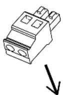
- Connect the TE-Phoenix connector to the existing wire ran in the wall. Next connect the TE cable into the back of the white TE Connector on the WallStation DC Adapter.


natural_image
Technical line drawing of an electronic device casing with internal components and wiring (no text or symbols)Zip tie the Connector to the DC board for added cable retnetion.
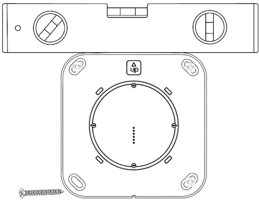
- Insert the CONNECT WallStation into the wall opening from the previous LAUNCH WallStation. IMPORTANT: Make Sure to position the WallStation with the Up Arrow facing up. Use a leveling tool to level the WallStation.

natural_image
Technical line drawing of a device casing with circular components and mounting holes (no text or symbols)- Use the old screws or provided screws to attach the WallStation to the preinstalled anchors.
natural_image
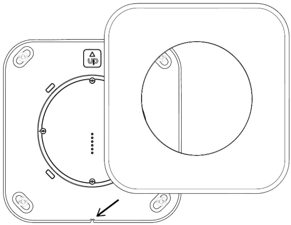
Technical line drawing of a mechanical component with mounting holes and a circular center (no text or symbols)- Attach the WallStation Cover Plate over the WallStation making sure to alight the positioning notch with the tooth on the WallStation.
natural_image
Technical line drawing of a device casing with circular components and mounting holes (no text or symbols)
natural_image
Simple circular diagram with four evenly spaced dots and a central dot, enclosed in a rounded square border (no text or symbols)- Place a Case with an iPad installed onto the WallStation to determine power was installed properly and the iPad charges.

natural_image
Line drawing of a tablet device with a circular screen and an attached rectangular frame, showing no text or symbols.IPORT CONNECT Pro WallStation Install
New Construction - 2 Wire
Before Construction is complete
- Determine the desired location of the IPORT CONNECT PRO WallStation will live when the construction is completed.

natural_image
Line drawing of a cabinet interior with doors and doors, no text or symbols present2. Install a 1 Gang electrical box or low voltage ring in the desired location of the WallStation.
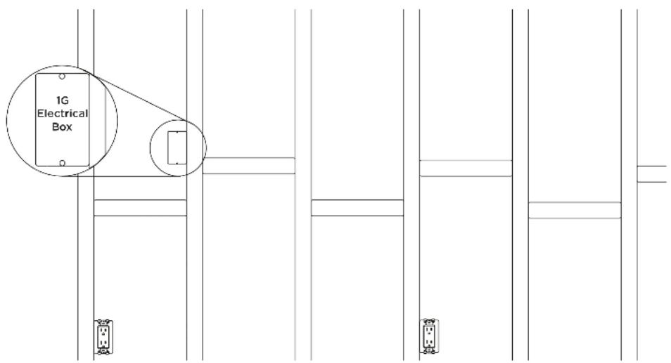
NOTE: The CONNECT PRO WallStation will cover a 1G electrical box only. A 2 Gang electrical box will interfere with the mounting hardware.

natural_image
Technical line drawing of a rectangular enclosure with mounting hardware and a circular checkmark below (no text or symbols)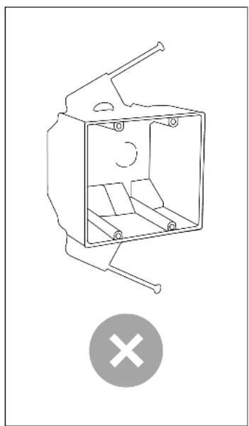
natural_image
Technical line drawing of a mechanical device with internal compartments and a cross symbol (no text or labels)4. Run a 14AWG 2 wire cable from the WallStation location to a nearby AC outlet, closet, or network rack location.
NOTE: Make sure to secure the 2 Wire cable appropriately onto the Electrical box or Low Voltage ring to retrieve at a later time.

natural_image
Technical line drawing of a rectangular enclosure with internal curved and mounting features (no text or symbols)Installing the WallStation After Construction
- Locate the 1 gang boxed saved for the WallStation and locate the end of the 2 wire for power.

natural_image
Technical line drawing of a U-shaped pipe or tube mounted on a rectangular base, with no visible text or symbols.
natural_image
Pure electrical circuit lines without any symbols
natural_image
Simple line drawing of a rectangular electrical outlet with three internal slots and two mounting holes (no text or symbols)Grommit not included
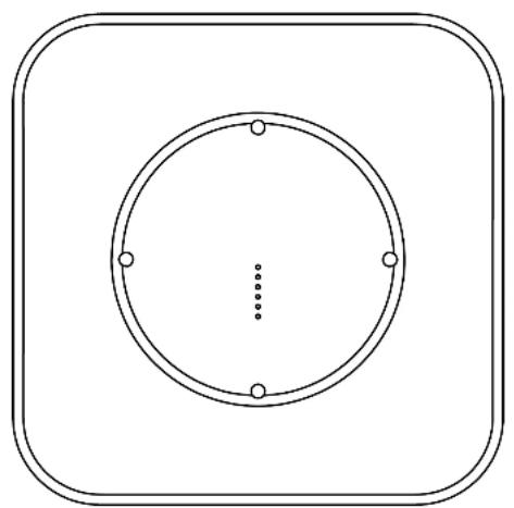
2. Remove the WallSation, Drywall anchors and Screws from the box and place on a table.
natural_image
Simple diagram of a circular ring with four evenly spaced dots inside, enclosed in a rounded square frame (no text or symbols)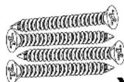
x4
x4
4. Insert the WallStation into the 1G box.
NOTE: the 1G box or low voltage ring was used to save the space of the WallStation. The WallStation was designed to be use without the need for a junction box. If possible remove the junction box or low voltage ring.

natural_image
Technical line drawing of a U-shaped mechanical component with mounting holes and a base plate (no text or symbols)
natural_image
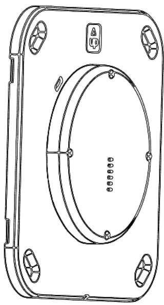
Technical line drawing of a rectangular electronic device with a circular housing and mounting holes (no text or symbols)- Use a leveling tool to level the WallStation and mark the 4 locations for the provided Anchors. Remove the WallStation from the 1G Box.

natural_image
Technical line drawing of a mechanical component with circular and rectangular features, no text or symbols present.6. Remove the WallStation and screw the provided anchors into the wall where marked.

natural_image
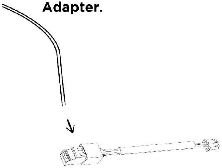
Technical line drawing of a U-shaped electrical component with mounting holes and a separate inset showing a sensor or connector (no text or symbols)- Connect the Phoenix to TE cable provided to the 14-2 wire and onto the White TE Connector on the WallStation DC Adapter.

natural_image
Technical line drawing of an internal electronic device casing with connectors and components (no text or symbols)Zip tie the Connector to the DC board for added cable retention.
- Insert the WallStation back into the 1G box and use the provided screws to attach the WallStation to the wall.
IMPORTANT: Make sure to position the WallStation with the Up Arrow facing up. Use a leveling tool to level the WallStation and hand tighten the screws.

natural_image
Technical line drawing of a mechanical component with mounting holes and a circular center (no text or symbols)- Attach the WallStation Cover Plate over the WallStation making sure to alight the positioning notch with the tooth on the WallStation.

natural_image
Technical line drawing of a device casing with mounting holes and a circular component, showing no text or symbols.
natural_image
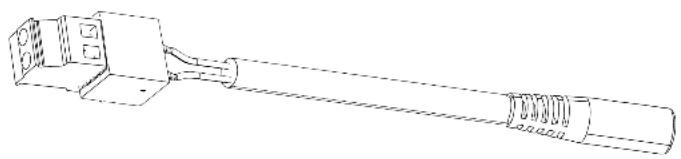
Simple circular diagram with four dots and a central dotted line, enclosed in a rounded square border (no text or symbols)- Connect the 2 wire to DC Connector at the other end of the 2 wire Cable.
natural_image
Technical line drawing of a mechanical component with no visible text or symbols- Connect the Provided DC Power Adapter into the wall and connect the barrel connector to the other end of the Phoenix adapter.

natural_image
Line drawing of two electrical connectors with wires and connectors, no text or symbols presentGrommit not included
For a clean finished look place the Connector and DC barrel plug back through the grommit into the wall.

- Place a Case with an iPad installed onto the WallStation to determine power was installed properly and the iPad charges.

natural_image
Line drawing of a tablet device with a circular screen and an attached rectangular frame, showing no text or symbols.WallStation Install Manual - Existing Construction - 2 Wire
- Determine the desired location of the IPORT CONNECT PRO WallStation.

- Use a 2-3/4" (70mm) hole saw to cut a hole in the desired location of the WallStation.

- Insert the WallStation into the 2 3/4 - inch hole and use a leveling tool to level the WallStation. Mark the 4 locations for the provided Anchors.

natural_image
Technical diagram of a mechanical component with circular center and mounting holes, showing directional arrows (no text or symbols)- Remove the WallStation form the wall once you have marked the 4 anchor locations.

natural_image
Technical line drawing of a square electronic device with a circular top and mounting holes, showing a circular arrow indicating rotation (no text or symbols)5. Screw the provided anchors into the wall where marked.

natural_image
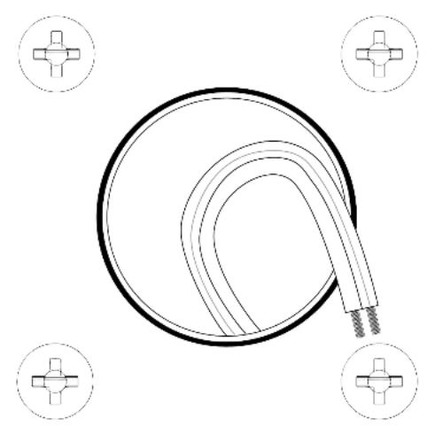
Technical drawing of a mechanical component with circular outline, crosshair symbol, and threaded end (no text or labels)- Use the 2 3/4 - inch hole to fish a 14/2 cable to a nearby AC outlet, closet or network rack.
natural_image
Pure diagram of a coiled cable with four circular markers at the corners (no text or symbols)
natural_image
Pure electrical circuit lines without any symbols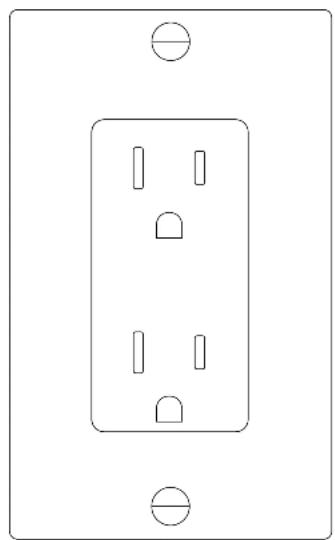
natural_image
Simple line drawing of a rectangular electrical outlet with four internal slots and two mounting holes (no text or symbols)WALLSTATION Existing Construction - 2 Wire
- Connect the Phoenix to TE cable provided to the 14-2 wire and onto the White TE Connector on the WallStation DC Adapter.


natural_image
Technical line drawing of an electronic device casing with internal components and a connector pin (no text or symbols)Zip tie the Connector to the DC board for added cable retnetion.
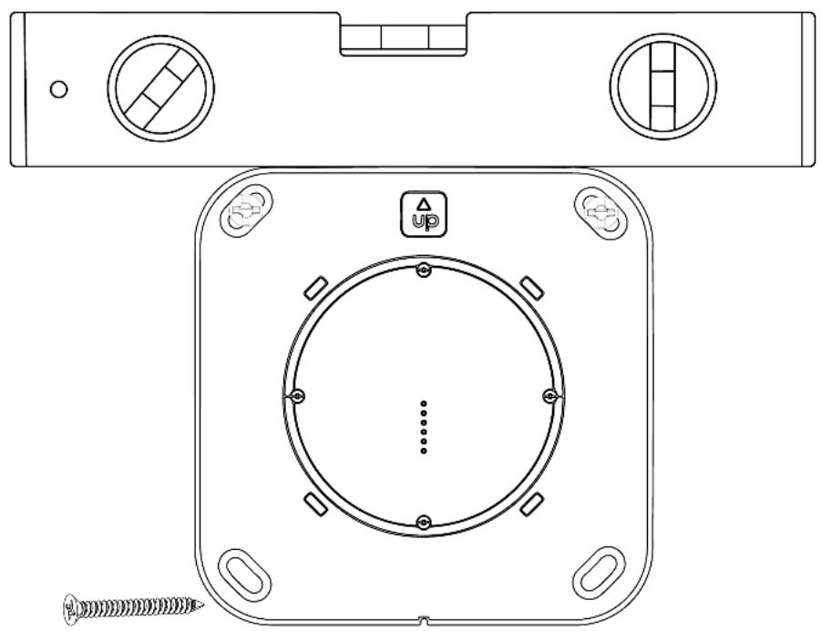
- Insert the WallStation back into the wall and use the provided screws to attach the WallStation to the wall anchors.
IMPORTANT: Make Sure to position the WallStation with the Up Arrow facing up. Use a leveling tool to level the WallStation and hand tighten the screws.
natural_image
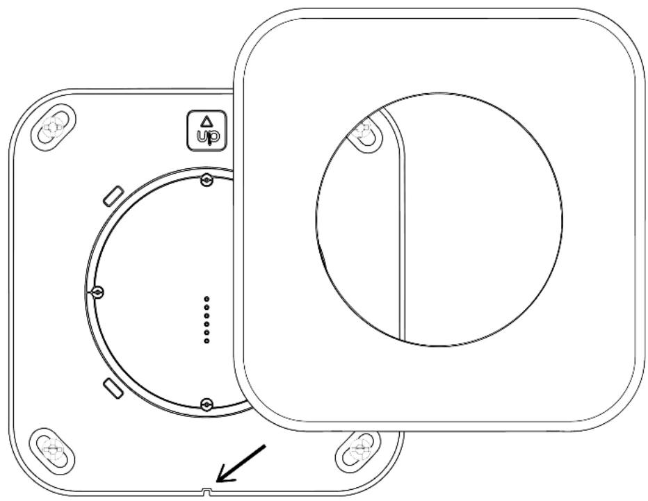
Technical line drawing of a mechanical component with mounting holes and a circular center (no text or symbols)- Attach the WallStation Cover Plate over the WallStation making sure to alight the positioning notch with the tooth on the WallStation.
natural_image
Technical line drawing of a device casing with circular components and mounting holes (no text or symbols)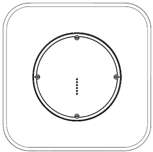
natural_image
Simple circular diagram with four evenly spaced dots and a central dot, enclosed in a rounded square border (no text or symbols)10. Connect the 2 wire to DC Connector at the other end of the 2 wire Cable.
natural_image
Technical line drawing of a mechanical component with no visible text or symbols11. Connect the Provided DC Power Adapter into the wall and connect the barrel connector to the other end of the Phoenix adapter.

natural_image
Line drawing of two connected electrical outlets with wires, no text or symbols presentGrommit not included
WALLSTATION
For a clean finished look place the Connector and DC barrel plug back through the grommit into the wall.

Grommit not included
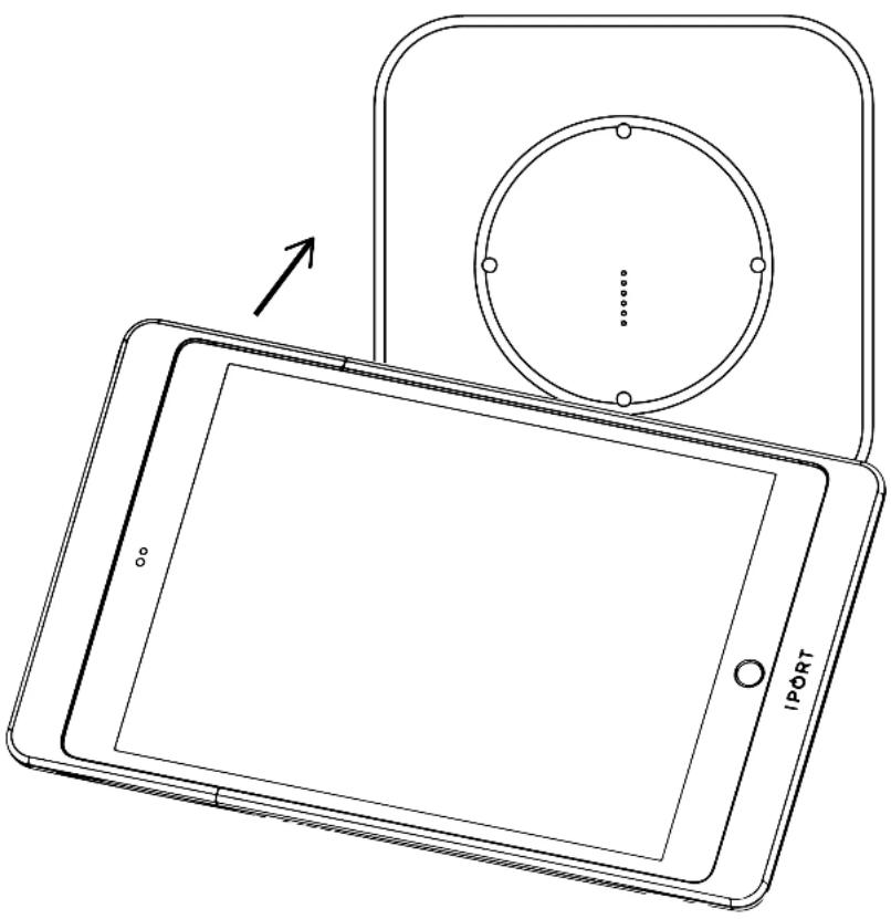
12. Place a Case with an iPad installed onto the WallStation to determine power was installed properly and the iPad charges.
natural_image
Line drawing of a tablet device with a circular screen and an attached rectangular frame, showing no text or symbols.- Whats in box:
- Glossary of Terms:
- WALLSTATION INSTALL OPTIONS
- IPORT CONNECT PRO WallStation Install New Construction - Cat6
- Before Construction is complete
- Determine the desired location of the IPORT CONNECT PRO WallStation will live when the construction is completed.
- Install a 1 Gang electrical box or low voltage ring in the desired location of the WallStation.
- Installing the WallStation After Construction
- Insert the WallStation into the 1G box.
- Insert the WallStation back into the 1G box and use the provided screws to attach the WallStation to the wall.
- Installing the WallStation in Existing Construction - Cat6
- Screw the provided anchors into the wall where marked.
- Terminate both ends the Cat6 with an RJ45 Connector using T568A or T568B standards
- Attach the WallStation Cover Plate over the WallStation making sure to alight the positioning notch with the tooth on the WallStation.
- WALLSTATION
- Upgrading a LAUNCH WallStation to CONNECT PRO
- Disconnect the two wires in the wall from the green phoenix connector.
- IPORT CONNECT Pro WallStation Install
- New Construction - 2 Wire
- Run a 14AWG 2 wire cable from the WallStation location to a nearby AC outlet, closet, or network rack location.
- Remove the WallSation, Drywall anchors and Screws from the box and place on a table.
- Insert the WallStation into the 1G box.
- Remove the WallStation and screw the provided anchors into the wall where marked.
- WallStation Install Manual - Existing Construction - 2 Wire
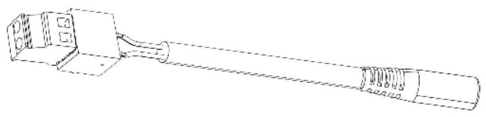
- Connect the 2 wire to DC Connector at the other end of the 2 wire Cable.
- Connect the Provided DC Power Adapter into the wall and connect the barrel connector to the other end of the Phoenix adapter.
- Place a Case with an iPad installed onto the WallStation to determine power was installed properly and the iPad charges.
Brand : iPort
Model : 72350
Category : Cables for Computers and Peripherals