UPS-1000R - Inverter Middle Atlantic - Free user manual and instructions
Find the device manual for free UPS-1000R Middle Atlantic in PDF.


| Product Type | Rackmounted Uninterruptible Power Supply (UPS) |
| Model Number | UPS-1000R |
| Capacity (VA / Watts) | 1000 VA / 750 Watts |
| Input Voltage Range | 80 VAC - 150 VAC |
| Input Frequency Range | 50/60 Hz ± 3 Hz (auto sensing) |
| Output Voltage (On Battery) | Pure Sine Wave at 120 VAC ± 7% |
| Output Frequency (On Battery) | 50/60 Hz ± 1% |
| Transfer Time | 4 ms (typical) |
| Output Receptacles | 8 x NEMA 5-15R |
| Dimensions (H x W x D) | 3.5 x 17.05 x 18.9 inches (8.8 x 43.3 x 48 cm) |
| Weight | 68.3 lb (31 kg) |
| Rack Form Factor | 2U |
| Battery Type | Sealed Maintenance-Free Lead Acid |
| Battery Capacity | 12V / 9.0 AH x 4 (internal) |
| Hot Swappable External Battery | Yes (supports up to 10 external packs, part # UPS-EBPR) |
| Automatic Voltage Regulation (AVR) | Yes, corrects low/high voltage without battery |
| Green Power Technology | Bypass mode reduces energy consumption when utility is normal |
| Communication Ports | USB, RS-232 (DB-9 primary and secondary), RJ11/RJ45 surge protection, optional NIC slot |
| Software | Middle Atlantic Power Manager (included) |
| EPO (Emergency Power Off) Port | Yes, supports normally open or normally closed switch |
| LED Indicators | Power On, Site Wiring Fault, LCD display (battery, AVR, load, etc.) |
| Audible Alarms | On battery, low battery, overload |
| Operating Temperature | 32°F to 104°F (0°C to 40°C) |
| Operating Humidity | 0 to 95% non-condensing |
| Safety Certifications | FCC Class B, UL listed (per NEC) |
Frequently Asked Questions - UPS-1000R Middle Atlantic
User questions about UPS-1000R Middle Atlantic
0 question about this device. Answer the ones you know or ask your own.
Ask a new question about this device
Download the instructions for your Inverter in PDF format for free! Find your manual UPS-1000R - Middle Atlantic and take your electronic device back in hand. On this page are published all the documents necessary for the use of your device. UPS-1000R by Middle Atlantic.
USER MANUAL UPS-1000R Middle Atlantic
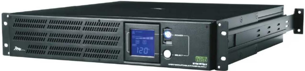
RACKMOUNTED UNINTERRUPTIBLE POWER SUPPLY
natural_image
Front view of a black energy harvesting power supply unit with digital display and control panel (no visible text or symbols on main body)MODEL NUMBERS
- UPS-1000R
- UPS-1000R-IP
- UPS-1000R-8IP
- UPS-2200R
- UPS-2200R-IP
- UPS-2200R-8IP
THANK YOU
Thank you for purchasing the 1000R or 2200R Series Rackmounted UPS. The UPS provides battery backup during power outages, automatic voltage regulation during periods of inconsistent utility power and surge protection.
IMPORTANT
Please read this manual before removing the UPS from the shipping carton and before making any connections to and operating your UPS.
TABLE OF CONTENTS
Important Safety Instructions 3 - 4
Middle Atlantic Products Green Power UPS Technology 5
FCC Warning 5 - 6
Circuit Diagram 6
Unpacking and Parts List 7
Installation and Mounting 7 - 8
Front Panel Descriptions 9
Rear Panel Descriptions (Bank Outlets) 9 - 10
Rear Panel Descriptions (Individual Outlets) 11 - 12
Setup Of (NIC) UPS-IPCARD 13 - 15
LCD Display Definitions 16
Battery Charging 17
Self Test 17
EPO (Emergency Power Off) Port Connection 17
Operation 18
General Status Mode 19
Functions Setup Mode 19 - 20
Battery Replacement 21 - 24
Optional External Battery Connection 24
Troubleshooting 25 - 26
Technical Specifications 27 - 28
Estimated Runtime 28 - 29
Warranty 29
Warranty Registration 30

IMPORTANT SAFETY INSTRUCTIONS READ AND SAVE THESE INSTRUCTIONS

This manual contains important instructions that should be followed during installation and maintenance of the UPS and batteries.

The lightning flash with the arrowhead symbol, within an equilateral triangle, is intended to alert the user to the presence of uninsulated dangerous voltage within the product's enclosure that may be of sufficient magnitude to constitute a risk of electric shock.

The exclamation point within an equilateral triangle is intended to alert the user to the presence of important operating and maintenance (servicing) instructions in the literature accompanying the product.

WARNING: The UPS must be connected to a grounded AC power outlet with fuse or circuit breaker protection. DO NOT plug the UPS into an outlet that is not grounded. If you need to de-energize this equipment, turn off and unplug the UPS.

WARNING: The internal battery in this UPS is always charged. The battery can energize hazardous live parts inside the unit, even when the AC input power is disconnected.

WARNING: To prevent the risk of fire or electric shock, install in a temperature and humidity controlled indoor area, free of conductive contaminants. (Please see specifications for acceptable temperature and humidity range).

WARNING: To reduce the risk of electric shock, do not remove the cover, except to service the battery. There are no serviceable parts inside, except for the battery.

WARNING: To avoid electric shock, turn off the unit and unplug it from the AC power before servicing the battery or installing a component.

WARNING: Do not use for medical or life support equipment. Do not use in any circumstance that would affect operation or safety of any life support equipment, with any medical applications, or patient care.

WARNING: Risk of battery explosion, if battery is replaced by an incorrect type or rating.

WARNING: Do not open or mutilate the batteries. Electrolyte is harmful to the skin and eyes and may be toxic.

WARNING: A battery can present a high risk of short circuit current or electrical shock.

WARNING: The battery may present the risk of electrical shock. Do not dispose of batteries in a fire, as they may explode. Follow all local ordinances regarding proper disposal of batteries.

CAUTION: Risk of energy hazard, 12V, 9AH battery. Before replacing batteries, remove conductive jewelry such as chains, wrist watches, and rings. High energy through conductive materials could cause severe burns.

CAUTION: To reduce the risk of fire, connect only to a circuit provided with 20 Amperes maximum branch overcurrent protection in accordance with the National Electrical Code, ANDI/NFPA 70.

CAUTION: Use only the specified type of battery. See your dealer for replacement batteries.

CAUTION: For PLUGGABLE EQUIPMENT, the socket-outlet shall be installed near the equipment

CONSIGNES DE SÉCURITÉ IMPORTANTES LIRE ET CONSERVER CES INSTRUCTIONS

Our new UPS circuit is designed to save energy operating in Green Power Bypass Mode.
A traditional UPS circuit with Automatic Voltage Regulation (AVR) provides normal output voltage through the relay and AVR transformer. The current travels first through the transformer conducting energy and generating heat. This heat creates energy dissipation resulting in a “Power Loss” or consumption of utility power and money.
Middle Atlantic Product's Green Power circuit design is a solution to this "Power Loss". When the utility power is operating normally, our Green Power UPS works in Bypass Mode. Our Green Power design conducts power only through the relay and still provides normal output voltage. Bypassing the transformer reduces power consumption thereby conserving energy and saving money. When the utility power is abnormal the UPS will operate under Battery or AVR Mode. Under this condition, Green Power UPS and a traditional UPS would operate about the same. On average, utility power operates 88% of the time and the Middle Atlantic Products Green Power Technology will work in its money/energy saving Bypass Mode.
FCC WARNING
NOTE: This equipment has been tested and found to comply with the limits for a Class B digital device, pursuant to Part 15 of the FCC Rules. These limits are designed to provide reasonable protection against harmful interference in a residential installation. This equipment generates, uses and can radiate radio frequency energy and, if not installed and used in accordance with the instructions, may cause harmful interference to radio communications. However, there is no guarantee that interference will not occur in a particular installation. If this equipment does cause harmful interference to radio or television reception, which can be determined by turning the equipment off and on, the user is encouraged to try to correct the interference by one or more of the following measures:
- Reorient or relocate the receiving antenna.
- Increase the separation between the equipment and receiver.
- Connect the equipment into an outlet on a circuit different from that to which the receiver is connected.
- Consult the dealer or an experienced radio/TV technician for help.
WARNING: A shielded-type power cord is required in order to meet FCC emission limits and also to prevent interference to the nearby radio and television reception. It is essential that only the supplied power cord be used. Use only shielded cables to connect I/O devices to this equipment.
WARNING: Any changes or modifications not expressly approved by the guarantee of this device could void the user's authority to operate the equipment.
FCC WARNING (CONTINUED)
UNPACKING AND PARTS LIST

CAUTION: DO NOT LIFT THE UPS WHILE HOLDING THE FRONT FACE OF THE UNIT. THIS MAY DAMAGE THE UNIT. ALWAYS LIFT THE UPS BY HOLDING IT BY BOTH SIDES.

ATTENTION: NE SOULEVEZ PAS L'UPS PAR LE FRONT DE L'UNITÉ COMME CELA PEUT ENTRAÎNER DOMMAGES. TOUJOURS SOULEVER UNITÉ DES DEUX CÔTÉS.
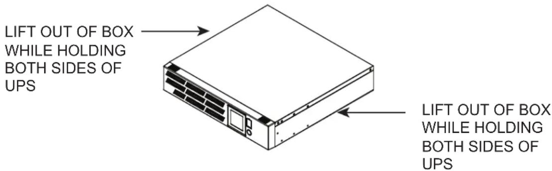
The UPS is very heavy and should be handled by two (2) people. After the product is removed from its shipping carton, inspect the UPS before installing and operating. The shipping carton should contain the following items:
(1) UPS unit; (1) User's Manual; (2) Rack ears; (14) 10-32 Rack ear screws; (8) Nylon rivets (Used to plug four front screw holes for mounting ears if the unit will not be rack mounted);
(1) Telephone Cable (black); (2) Rackmount handles; (4) 8-32 Rackmount handle screws;
(1) Emergency Power Off Cable (gray); (1) Middle Atlantic Power Manager Software CD;
(2) Serial Interface Cable (DB-9); (1) USB cable; (1) Warranty Registration Card
INSTALLATION AND MOUNTING
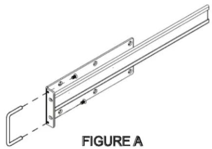
1) If using the provided handles install them now using provided 8-32 screws. (FIGURE A)
NOTE: The handles cannot be installed after the unit is rack-mounted.
natural_image
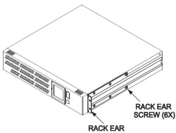
Technical line drawing of a mechanical bracket assembly with mounting holes and a dashed extension (no text or symbols)2) Install ears as shown using provided 10-32 screws. Six screws per ear, one ear per side.
INSTALLATION AND MOUNTING (CONTINUED)

CAUTION: THIS UNIT IS HEAVY,,LIFT CAREFULLY


ATTENTION: CET APPAREIL EST LOURD, SOULEVEZ AVEC ATTENTION

One Person Installation:
1) Determine mounting location.
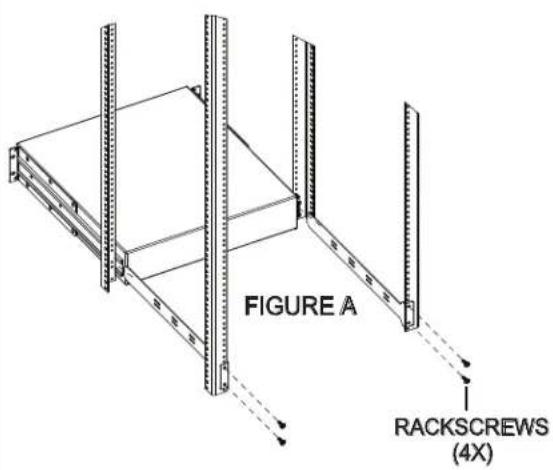
2) Install the Rear Mounting Brackets as shown. One Bracket is longer then the other to provide guidance when doing a one person installation. These brackets are interchangeable. (FIGURE A)
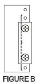
IMPORTANT NOTE: Rear Mounting Brackets mount between the two corresponding rackspaces in the front of the enclosure. (FIGURE B)
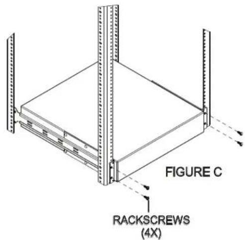
3) Carefully lift the unit to the mounting position constantly supporting the bottom. Place the slide on the unit's ear onto the longer Rear Mounting Bracket then guide the unit onto the other Rear Mounting Bracket. Once the ears and the Rear Mounting Brackets are fully engaged, slide to unit to the back of the enclosure.
4) Install the front of the unit to the rackrail. (FIGURE C)
Two Person Installation:
1) Determine mounting location.
2) Properly support the unit from the bottom and carefully lift to the mounting location.
3) While adequately supporting the bottom, install the front of the unit to the rackrail. (FIGURE D)
4) Install the Rear Mounting Brackets as shown. Continue to support the bottom of the unit. (FIGURE E) IMPORTANT NOTE: Rear Mounting Brackets mount between the two corresponding rackspaces in the front of the enclosure. (FIGURE B)
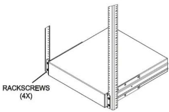
FIGURE D FIGURE E
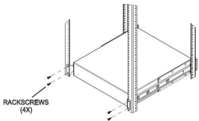
FIGURE E
FRONT PANEL DESCRIPTIONS
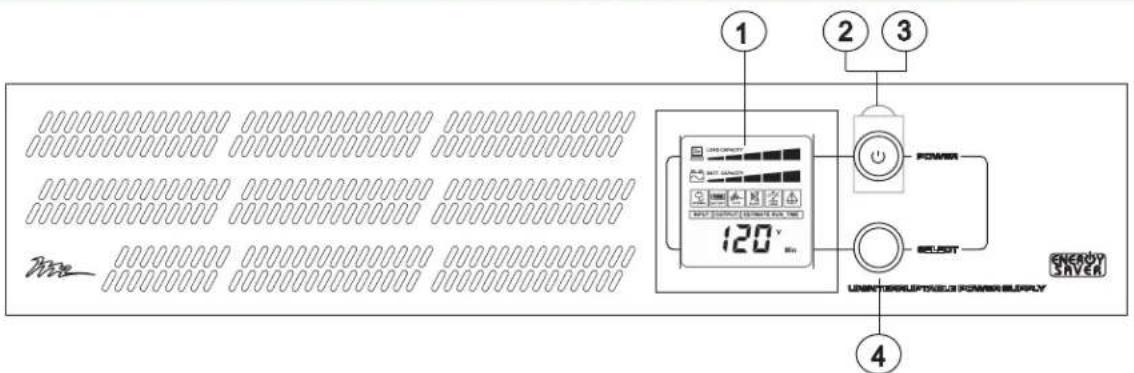
① LCD display: The LCD display indicates a variety of UPS operational conditions (see page 14 for LCD display definitions).
② Power Switch: On/off switch to turn UPS on and off.
③ Power on indicator: Indicates the UPS is turned on.
④ LCD display toggle button: Toggles between a variety of UPS operational conditions (see page 14).
REAR PANEL DESCRIPTIONS - BANK OUTLETS
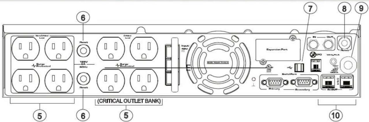
⑤ AC Outlets: All AC outlets provide connected equipment with AC line power, surge protection and line noise filtering during normal operation. Automatic voltage regulation corrects low voltage and high voltage conditions without using battery power. All outlets provide battery power during blackouts and severe brownout or severe high voltage conditions. The Non-Critical Load outlet bank can be configured to automatically shut down during a power outage event providing longer up-time for equipment plugged into the Critical Load outlet bank.
⑥ AC Output circuit breakers: Resettable circuit breakers provides AC output overload protection.
⑦ USB port: Connects UPS to your computer via the supplied USB cable for UPS setup, configuration and unattended shutdown in the event of a power failure. For use with the supplied Middle Atlantic Power Manager software. (Please Note: The USB and Serial ports may not be used simultaneously)
⑧ Input circuit breaker: Resettable circuit breaker provides input overload protection.
⑨ Input power cord: Heavy-duty permanently attached SignalSafe ^TM power cord, connects UPS to mains power.
⑩ Communication protection ports RJ11/RJ45: Protects against surges on a single phone, fax, modem or Ethernet network lines.
REAR PANEL DESCRIPTIONS - BANK OUTLETS (CONTINUED)
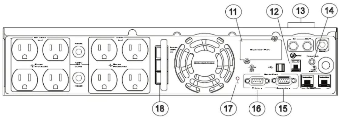
⑪ Expansion Port: Slot for Network Interface Card (NIC). Part Number UPS-IPCARD. (See pg 11 - 13 for installation steps)
⑫ EPO (Emergency Power Off) Port: The EPO port may be used to connect the UPS to a contact closure switch or control system to enable emergency shutdown (see page 15).
13 Coax/Cable/DSS Surge Protection: The Coax/Cable/DSS surge protection ports will provide surge protection to cable modem, CATV converter or DSS receiver.
⑭ Site Wiring Fault Input LED Indicator: This LED will illuminate to warn the user that a wiring problem exists within the AC mains electrical supply receptacle, such as reversed wiring. If illuminated, disconnect all equipment and contact an electrician to ensure the outlet is properly wired.
SERIAL PORT PRIMARY CONNECTOR PINOUT
| Pin No | Description |
| 1 | Indicates battery condition. If battery low condition occurs, pin 1 is (low), otherwise pin 1 will be (high). |
| 3 | Ground. Connect to ground (common) of control system I/O. |
| 4/5 | Connect Pin4 with Pin7 and Pin5 with Pin3 for 12-15 second to trigger UPS S/D sequence on inverter mode. |
| 7 | +9VDC to + 12VDC must be applied to pin 7 from control system I/O in order for analog communication. |
| 8 | Indicates utility power condition. If a power failure occurs pin 8 is (low) otherwise pin 8 is (high). |
Note: Primary DB-9 supports RS-232 as well as analog contact operation
15 Serial Port Secondary I/O: Analog input/output pinout shown below will provide status for remote monitoring of the UPS.
⑯ Serial Port Primary: The serial port primary allows for communication with a PC (through RS232) or a control system. (Please Note: The USB and Serial ports may not be used simultaneously)
17 Ground stud: Supplemental Bonding Point. Bonding of this point to the equipment and/or enclosure helps ensure optimum performance of the electronic system.
18 External Battery Pack Connector: Use to connect the optional MAP external battery pack (Part No. UPS-EBPR) for extended UPS runtime. A maximum of ten (10) battery packs can be daisy-chained together.
REAR PANEL DESCRIPTIONS - INDIVIDUAL OUTLETS
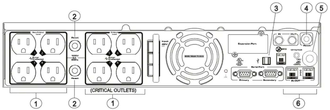
① AC Outlets (Individually Controlled): All AC outlets provide connected equipment with AC line power, surge protection and line noise filtering during normal operation. Automatic voltage regulation corrects low voltage and high voltage conditions without using battery power. All outlets provide battery power during blackouts and severe brownout or severe high voltage conditions. The Non-Critical Load outlets can be configured to automatically shut down during a power outage event providing longer up-time for equipment plugged into the Critical Load outlets.
② AC Output circuit breakers: Resettable circuit breakers provides AC output overload protection.
③ USB port: Connects UPS to your computer via the supplied USB cable for UPS setup, configuration and unattended shutdown in the event of a power failure. For use with the supplied Middle Atlantic Power Manager software. (Please Note: The USB and Serial ports may not be used simultaneously)
④ Input circuit breaker: Resettable circuit breaker provides input overload protection.
⑤ Input power cord: Heavy-duty permanently attached SignalSafe ^TM power cord, connects UPS to mains power.
⑥ Communication protection ports RJ11/RJ45: Protects against surges on a single phone, fax, modem or Ethernet network lines.
REAR PANEL DESCRIPTIONS - INDIVIDUAL OUTLETS (CONTINUED)
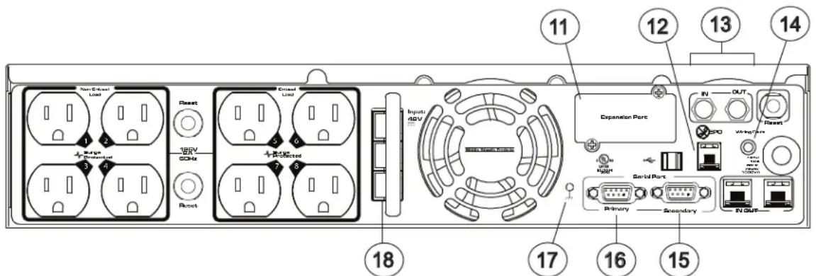
⑪ Expansion Port: Slot for optional Network Interface Card (NIC). Part Number UPS-IPCARD. (See pg 11 -13 for installation steps.
⑫ EPO (Emergency Power Off) Port: The EPO port may be used to connect the UPS to a contact closure switch or control system to enable emergency shutdown (see page 15).
13 Coax/Cable/DSS Surge Protection: The Coax/Cable/DSS surge protection ports will provide surge protection to cable modem, CATV converter or DSS receiver.
⑭ Site Wiring Fault Input LED Indicator: This LED will illuminate to warn the user that a wiring problem exists within the AC mains electrical supply receptacle, such as reversed wiring. If illuminated, disconnect all equipment and contact an electrician to ensure the outlet is properly wired.
SERIAL PORT SECONDARY CONNECTOR PINOUT
| Pin No | Description |
| 1 | Indicates battery condition. If battery low condition occurs, pin 1 is (low), otherwise pin 1 will be (high). |
| 3 | Ground. Connect to ground or common of control system I/O. |
| 7 | +9VDC to + 12VDC must be applied to pin 7 from control system I/O in order for analog communication. |
| 8 | Indicates utility power condition. If a power failure occurs pin 8 is (low) otherwise pin 8 is (high). |
⑮ Serial Port Secondary I/O: Analog input/output pinout shown below will provide status for remote monitoring of the UPS.
16 Serial Port Primary: The serial port primary allows for communication with a PC (through RS232) or a control system. (Please Note: The USB and Serial ports may not be used simultaneously)
17 Ground stud: Supplemental Bonding Point. Bonding of this point to the equipment and/or enclosure helps ensure optimum performance of the electronic system.
18 External Battery Pack Connector: Use to connect the optional MAP external battery pack (Part No. UPS-EBPR) for extended UPS runtime. A maximum of ten (10) battery packs can be daisy-chained together.
SETTING UP UPS-IPCARD
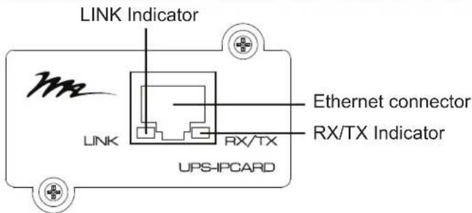
Definitions for LED Indicators
| Link LED color | Condition |
| Off | The UPS Network Interface Card is not connected to the Network or the UPS Network Interface Card power is off |
| On (Yellow) | The UPS Network Interface Card is connected to the Network |
| RX/TX LED color | |
| Off | The UPS Network Interface Card power is off |
| On (Green) | The UPS Network Interface Card power is on |
| Flashing | - Receiving/transmitting data packet- Reset completed |
Configuring the IP address for the Middle Atlantic Network Interface Card
Method 1: Using the SNMP Card Configuration Tool
1) Install the SNMP Card Configuration Tool from the included CD. It is located on the CD in the \tools\network folder. Double click the installation file "MAP_SNMP_Setup.msi" to begin the installation.
2) After the installation is complete, run the "Middle Atlantic UPS-IPCARD Setup Utility" program. Under "All Programs", select "Middle Atlantic Products > UPS-IPCARD".
3) The main screen of the SNMP Card Configuration Tool program is shown in (FIGURE A). The configuration tool will display all Middle Atlantic UPS Network Interface Cards present on the network. Click "Refresh" to search for newly added devices
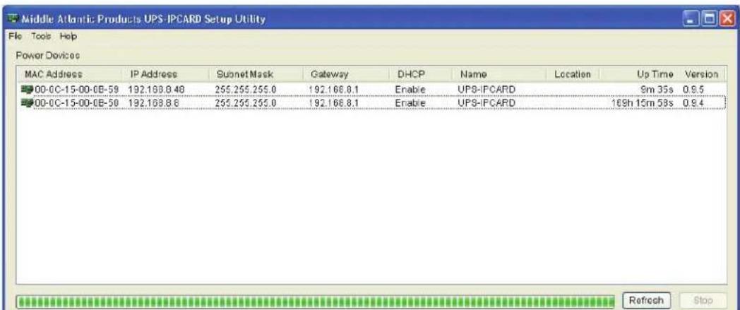
(FIGURE A)
SETTING UP UPS-IPCARD (CONTINUED)
4) Select the SNMP card you are setting up. Click on the Tools menu and select "Device Setup" or double click the SNMP card you want to configure.
5) You can modify the IP Address, Subnet Mask, and Gateway address for the Device MAC Address listed in the Device Network Settings window, as shown in (FIGURE B). The default IP Address is 192.168.20.177, the default Subnet Mask is 255.255.255.0.
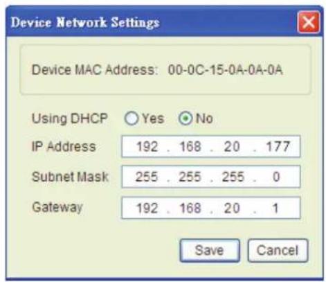
(FIGURE B)
6) Modify the IP, subnet mask or gateway address. Enter the new addresses into the corresponding fields.
7) You will need to enter a password for the SNMP card in the authentication window as shown in (FIGURE C). Default user name: admin. Default password: admin.
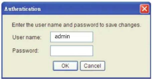
(FIGURE C)
8) If the IP address is successfully set, you will see a message that the IP setup is okay. (FIGURE D)
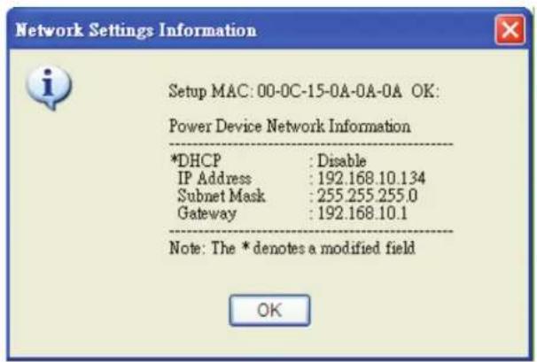
(FIGURE D)
SETTING UP UPS-IPCARD (CONTINUED)
Method 2: Using a Command Prompt
1) Obtain the MAC address from the label on the UPS Network Interface Card rear panel. Each UPS Network Interface Card has a unique MAC address.
2) Use the ARP command to set the IP address. Example: To assign the IP Address 192.168.20.240 for the UPS Network Interface Card, which has a MAC address of 00-0C-15-00-00-01 you will type in the following command prompt from a PC connected to the same network as the UPS Network Interface Card. (1) Type in “arp-s 192.168.20.240 00-0C-15-00-00-01” then press ‘Enter’.
3) Use the Ping command to assign a size of 123 bytes to the IP. (1) Type in "ping 192.168.20.240 -1 123" then press 'Enter'.
Method 3: Login from a Web Interface
1) Type the IP address of the UPS in your web browser and hit 'Enter' to access the UPS.
There are two user account types.
- Administrator (default username : admin ; default password : admin)
- Viewer (default username : guest ; default password : guest)
The administrator can access all functionality including enable/disable the guest account. The guest account can access “read only” functionality but can not control or change any settings
2) The IP address can be changed by accessing the system>tcp/ip menu. Refer to the MAP UPS-IPCARD User's Manual for more detail (I-00453).
LCD DISPLAY DEFINITIONS
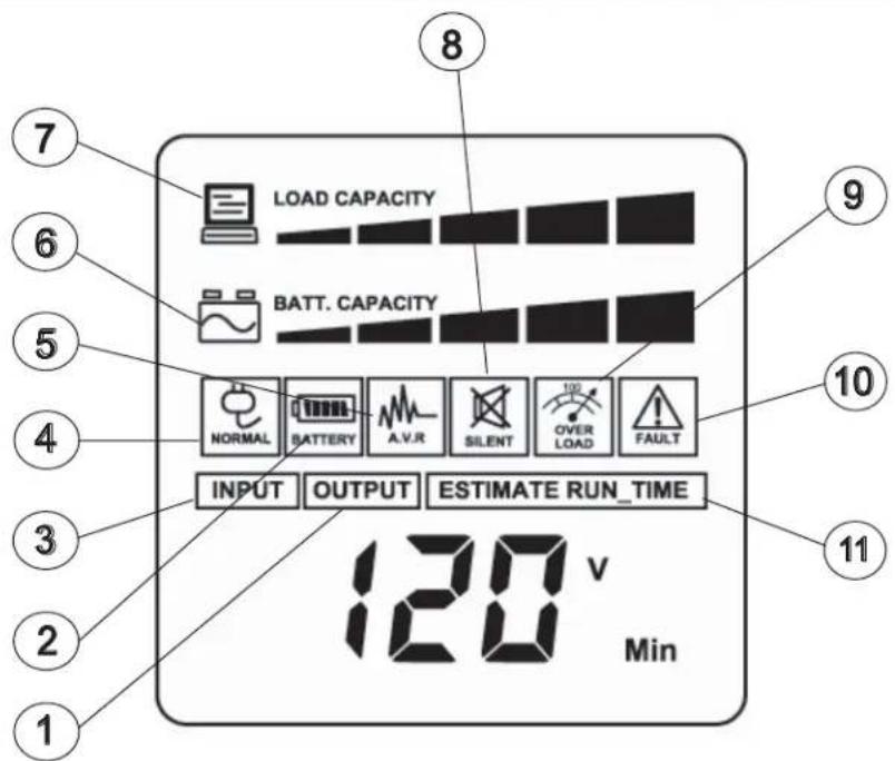
① Output Meter: Displays the output AC voltage, frequency and wattage that the UPS is providing.
② Battery Icon: When operating on battery, this icon appears and an alarm sounds (two short beeps followed by a pause) indicating the UPS is operating from its internal battery.
③ Input Voltage Meter: Measures the incoming AC voltage that the UPS is receiving from the mains power connection.
④ Normal Icon: This icon appears when the UPS is functioning normally.
⑤ AVR (Automatic Voltage Regulator): This icon appears whenever the UPS is automatically correcting low or high input AC line voltage without using battery power. This is a normal, automatic operation of the UPS, no operator action is required.
⑥ Battery Capacity Meter: This meter displays the approximate charge level (in 20% shaded increments) of the UPS's internal battery and external battery.
⑦ Load Capacity Meter: This meter displays the approximate output load level (in 20% shaded increments) of the UPS's AC outlets
⑧ Silent Mode Icon: This icon appears whenever the UPS is in silent mode. The buzzer can be turned on or off by the user and does not beep during silent mode until the battery reaches low capacity.
⑨ Overload Icon: This icon appears and an alarm sounds to indicate that the AC outlets are overloaded. To clear the overload, first turn the power off on each equipment and unplug from the AC outlets one at a time, until the overload icon disappears and the alarm stops.
10 Fault Icon: This icon appears if there is a problem with the UPS. Contact Middle Atlantic Products at 1-800-266-7225 for further help and support.
⑪ Estimate Runtime: This displays the runtime estimate of the UPS with the current battery capacity and load.
BATTERY CHARGING
The UPS is shipped from the factory with its internal battery fully charged. However, the battery may lose some charge during shipping and storage. Recharging the battery for at least four hours is recommended to ensure that the battery's maximum charge capacity is achieved.
The UPS is equipped with an auto-charge feature. When the UPS is plugged into mains AC supply voltage, the battery will automatically recharge (the battery will charge with the UPS either turned on or off). To maintain optimal battery charge, leave the UPS plugged into an AC outlet at all times.
SELF TEST
The UPS features a built-in self test which verifies the operation of the UPS and the condition of the battery. During self test, the UPS is powered by its internal battery.
1) With the UPS turned on, press and hold the Select button for approximately 5 seconds until the UPS starts to beep. Release the button.
2) The Battery icon will appear on the LCD Display. After approximately 10 or more seconds, the UPS will revert back to normal mode.
EPO (EMERGENCY POWER OFF) PORT CONNECTION
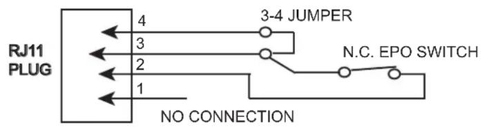
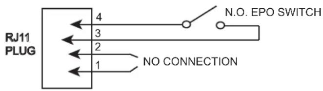
This feature is for those applications that require connection to an Emergency Power Off (EPO) circuit in case of fire or other emergency situation. When the UPS is connected to this circuit, it enables emergency shutdown of the UPS's inverter. Using the supplied gray cable, connect the EPO port of your UPS to a user-supplied normally closed or normally open switch according to the circuit diagram shown below. Press the Power switch twice to turn on the UPS after making the connections.
OPTION 1: USER SUPPLIED NORMALLY CLOSED SWITCH
OPTION 2: USER SUPPLIED NORMALLY OPEN SWITCH
OPERATION
CAUTION: DO NOT plug a laser printer, copier, space heater, vacuum, paper shredder or other large electrical device into the UPS. The power demands of these devices will overload and possibly damage the UPS.
1) Plug the UPS into a grounded wall receptacle. Ensure the wall receptacle is protected by a fuse or circuit breaker and does not service other equipment with large electrical demands (i.e. air conditioner, refrigerator, copier, etc.)
2) Press the Power Switch to turn the UPS on. The Power On Indicator will illuminate.
NOTE: If an overload is detected, an audible alarm will sound and the UPS will emit one long beep. To correct this, first turn the power off on a piece of equipment and unplug that piece of equipment from the UPS. Wait approximately 10 seconds and reconnect the piece of equipment to the UPS and turn it on. If after reconnecting, the overload alarm sounds, turn off the piece of equipment, remove from the UPS and connect it to another power source.
GENERAL STATUS MODE
1) Press the Select button on the front panel to view each UPS status item listed in Table 1. Each item will display in the order shown.
NOTE: The LCD display backlight will automatically turn off if the Select button is not pressed for more than 30 seconds.
| ORDER STATUS ITEM UNIT | ||
| 1 | Input Voltage V | |
| 2 | Output Voltage V | |
| 3 | Output Frequency Hz | |
| 4 | Load Kw | |
| 5 | Estimate Run Time Min | |
| 6 | Load Capacity % | |
| 7 | Battery Capacity % | |
| 8 | Temperature °C | |
| 9 | Temperature °F | |
TABLE 1
SETTING UP UPS-IPCARD (CONTINUED) FUNCTIONS SETUP MODE
1) Refer to Table 3 for a list of the functions which are configurable.
2) To enter setup mode, press and hold the Select button on the front panel for approximately 5 or more seconds. The UPS will start beeping, release button after six beeps. The LCD display will show six icons (Normal, Battery, A.V.R., Silent, Overload, and Fault).
NOTE: 1) If there is no user action for more than 30 seconds, the LCD backlight will turn off and the UPS will return to the "General Status Mode".
2) The user can return to "General Status Mode" at anytime by waiting for the LCD backlight to turn off or by pressing and holding the Select button for approximately 10 or more seconds.
3) Pressing the Select button will display each function listed in Table 2 in the order given.
| ORDER | FUNCTION | UNIT |
| 1 | Delay Time | Min |
| 2 | Number of Expansion Battery Packs | 1-10 |
| 3 | Static Frequency Tolerance | Hz |
| 4 | Slew Rate | Hz |
| 5 | Battery Shutdown Voltage | V |
| *6 | Firmware version |
* Not configurable
TABLE 2
4) To change functions, press and hold the Select button until the six icons are blinking on and off. Press the Select button to enter the desired value.
5) To save the value, press and hold the Select button for approximately 4 seconds. The LCD display will return to the General Status Mode Input Voltage Display. Repeat steps 1 through 4 each time any of the function values are to be changed.
FUNCTIONS SETUP MODE (CONTINUED)
| FUNCTION DESCRIPTION | DEFAULT SETTING | |
| Delay Time | The time delay switching from battery mode to line mode. There are 9 different settings: (0, 0.5, 1.0, 1.5, 2.0, 2.5, 3.0, 3.5, 4.0) seconds | 0 |
| Number of Expansion Battery Packs | This function defines the number of external battery packs connected to the UPS: (one - ten) | 0 (no external battery packs connected) |
| Static Frequency Tolerance | Setting is dependant on the quality of the supplied AC power. There are 4 different settings: (1%, 2%, 4% and 6%) | 6% |
| Slew Rate | Indicates the tolerance of a device in accepting frequency variations. The lower slew rate results in less tolerance but better protection for the connected loads. There are 5 different settings: (0.25 Hz, 0.5 Hz, 1 Hz, 2 Hz, 4 Hz) | 4 Hz |
| Battery Shutdown Voltage | Adjusts the UPS shutdown point according to the remaining battery voltage. There are five different settings: 38VDC, 39VDC, 40VDC, 41VDC and 42VDCPlease note that selecting a higher shutdown voltage will extend battery life, but decrease on-battery run-time | 40 VDC |
TABLE 3. Configurable Parameters
BATTERY REPLACEMENT
Contact your dealer or call the number in this manual for information on battery replacement. Read and follow the IMPORTANT SAFETY INSTRUCTIONS before servicing the battery. Service the battery under the supervision of personnel who are knowledgeable about batteries and their precautions. Servicing of the battery can only be performed by trained personnel.

IMPORTANT SAFETY INSTRUCTIONS READ AND SAVE THESE INSTRUCTIONS

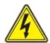
The lightning flash with the arrowhead symbol, within an equilateral triangle, is intended to alert the user to the presence of uninsulated dangerous voltage within the product's enclosure that may be of sufficient magnitude to constitute a risk of electric shock.

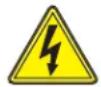
The exclamation point within an equilateral triangle is intended to alert the user to the presence of important operating and maintenance (servicing) instructions in the literature accompanying the product.
WARNING: Risk of battery explosion, if battery is replaced by an incorrect type or rating.

WARNING: Do not open or mutilate the batteries. Electrolyte is harmful to the skin and eyes and may be toxic.

WARNING: A battery can present a high risk of short circuit current and electrical shock.

WARNING: The battery may present the risk of electrical shock. Do not dispose of batteries in a fire, as they may explode. Follow all local ordinances regarding proper disposal of batteries.

CAUTION: To reduce the risk of fire, connect only to a circuit provided with 20 Amperes maximum branch overcurrent protection in accordance with the National Electrical Code, ANDI/NFPA 70.

CAUTION: Use only the specified type of battery. See your dealer for replacement batteries.
The following precautions should be observed before replacing the battery:
- Remove all watches, rings or other metal objects.
- Only use tools with insulated handles.
- Do not lay tools or metal parts on top of battery or any terminals.
- Wear rubber gloves and boots.
- Determine if the battery is inadvertently grounded. If inadvertently grounded, remove the ground source. CONTACT WITH GROUNDED BATTERY CAN RESULT IN ELECTRICAL SHOCK! The likelihood of such shock will be reduced if such grounds are removed during installation and maintenance (applicable to a UPS and a remote battery supply not having a grounded circuit.)
BATTERY REPLACEMENT (CONTINUED)
BATTERY REPLACEMENT (CONTINUED)

CAUTION: The battery is heavy, use caution when removing
ATTENTION: LA BATTERIE EST LOURD, SOYEZ PRUDENT LORSQUE VOUS RETIREZ


1) Power off the unit and disconnect it from its AC power source.
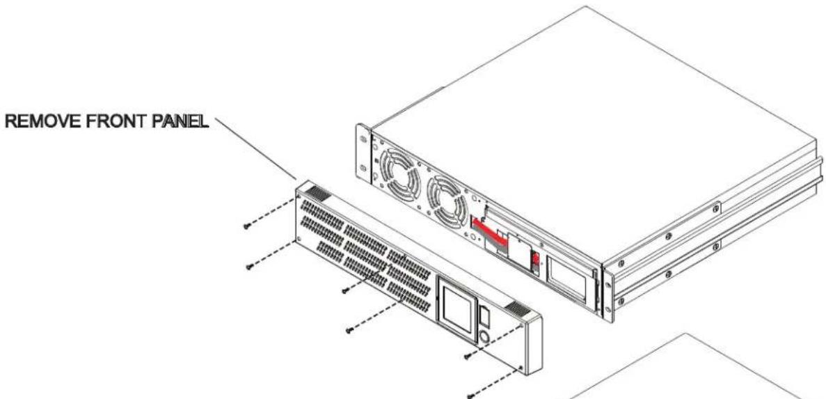
2) Remove the front panel by removing six screws then grasping it on the left hand side and pulling it away from the unit. Remove the right side of the panel to detach it from the unit.
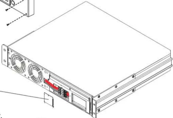
3) Remove the retaining screws securing the cable protection cover to the UPS and remove the cover.
REMOVE CABLE PROTECTION COVER
natural_image
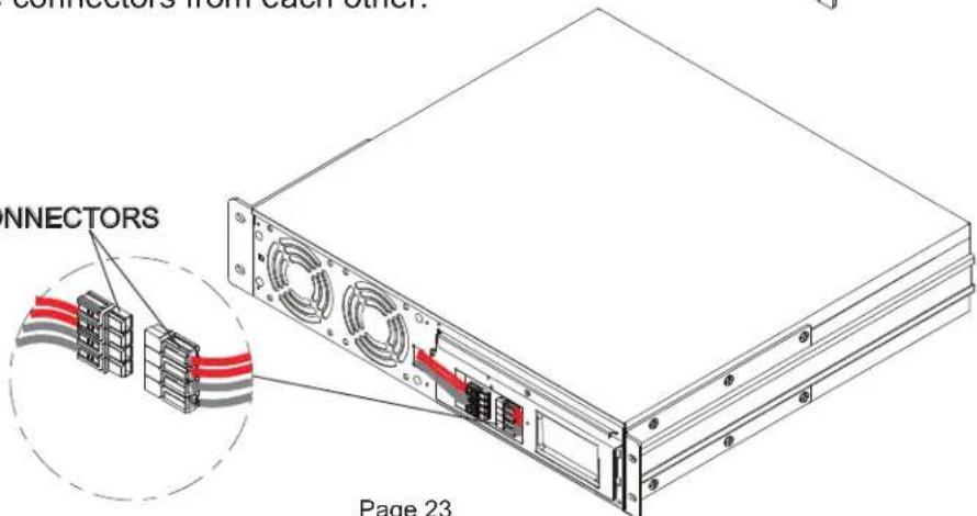
Technical line drawing of a server rack with ventilation fans and drive slots (no text or symbols)4) Disconnect the cable connectors from each other.
DISCONNECT CABLE CONNECTORS
BATTERY REPLACEMENT (CONTINUED)
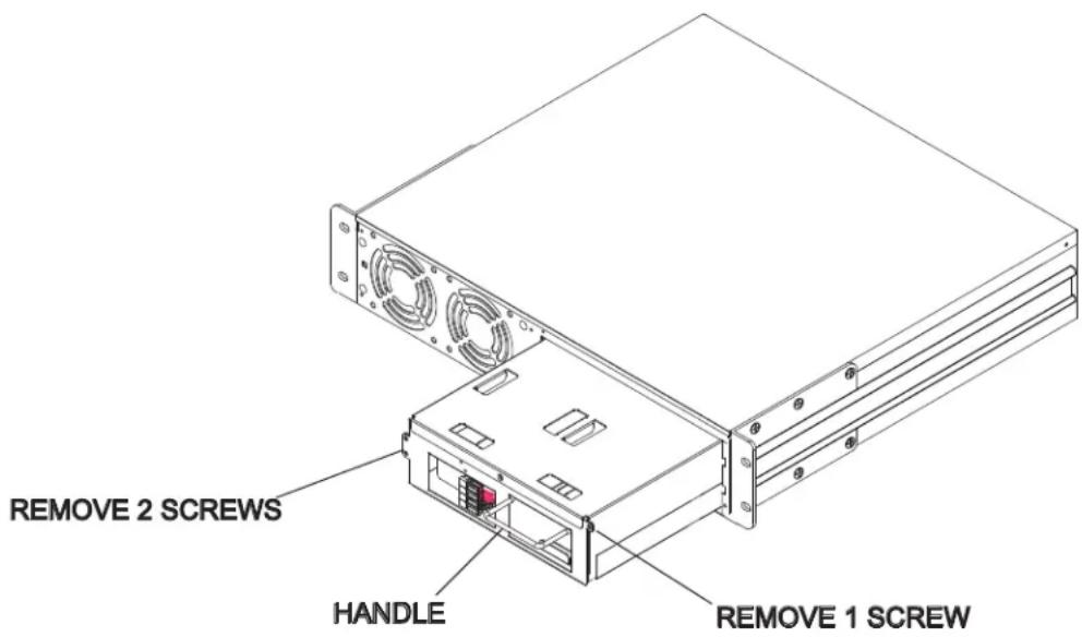
5) Remove three battery retaining screws (2 on left side, and 1 on the right side) and pull the battery out using the handle.
6) Insert replacement battery (Part No. UPS-RBP) and perform steps 2 - 4 in reverse. To reinstall the faceplate, reinstall six screws.
- Recharge the battery for 4-8 hours to ensure that the UPS meets the expected on-battery runtime -
OPTIONAL EXTERNAL BATTERY
All UPS models feature a connector that accepts an optional external battery pack (Part Number UPS-EBPR, sold separately) that provides additional runtime and increases UPS battery recharge time. The external battery packs can be daisy chained up to a maximum of ten battery packs.
TROUBLESHOOTING
| Problem | Possible Cause | Solution |
| Outlets do not provide power to equipment. | 1. Circuit breaker has tripped due to an overload.2. Batteries are discharged3. Unit has been damaged by a surge or spike.4. Non critical outlets have turned off automatically due to an overload. | 1. Turn the UPS off and unplug at least one piece of equipment. Wait 10 seconds, reset the circuit breaker, and then turn on the UPS.2. Recharge the unit for at least 4 hours.3. Contact Middle Atlantic Products at 1-800-266-7225.4. Push the bottom Reset button to turn on the Non critical outlets. |
| The UPS does not perform the expected runtime. | 1. Battery is not fully charged.2. Battery is degraded. | 1. Recharge the battery by leaving the UPS plugged in.2. Contact Middle Atlantic Products about replacement batteries at 1-800-266-7225. |
| The UPS will not turn on. | 1. The on/off switch is designed to prevent damage by rapidly turning it on and off.2. The UPS is not connected to an AC outlet.3. The battery is degraded.4. Mechanical problem. | 1. Turn the UPS off. Wait 10 seconds and then turn the UPS on.2. The UPS must be connected to a 110/120V outlet.3. Contact Middle Atlantic Products about replacement batteries at 1-800-266-7225.4. Contact Middle Atlantic Products at 1-800-266-7225. |
| Middle Atlantic Power Manager software is inactive | 1. The serial cable or USB cable is not connected.2. The cable is connected to the wrong port.3. The unit is not providing battery power.4. The serial cable is not the cable that was provided with the unit. | 1. Connect the cable to the UPS. You must use the cable that came with the UPS.2. Ensure that either the USB or DB-9 cable is connected to the correct port on both the UPS and the computer.3. Shutdown your computer and turn the UPS off. Wait 10 seconds and turn the UPS back on. This should reset the unit.4. You must use the cable included with the unit for the software. |
TROUBLESHOOTING NETWORK INTERFACE CARD
| Problem | Solution |
| Unable to configure the UPS Network Interface Card by method 1 or method 2. | 1. Check the LED status, the normal condition is both yellow and green led is on.If green LED is off: Check if the UPS Network Interface Card is properly seated in the UPS and the UPS power is on.If yellow LED is off: Check if the network connection is valid.2. Check if the operated PC is on the same physical network as UPS Network Interface Card is. |
| Unable to ping the UPS Network Interface Card. | 1. Use method 1 and method 2 to get correct IP address of the UPS Network Interface Card.2. If the operated PC is on the different physical network from the UPS Network Interface Card, verify the setting of subnet mask and the IP address of gateway. |
| Forgotten user name and password. | Please refer to the “Reset to Default Setting/Recover from a Forgotten Password” section in the UPS-IPCARD user manual (I-00453). |
TECHNICAL SPECIFICATIONS
| MODEL | UPS-1000R Series | UPS-2200R Series |
| Capacity (VA) | 1000 | 2150 |
| Capacity (Watts) | 750 | 1650 |
| INPUT | ||
| Cord Length & Plug Type | 9ft. & NEMA 5-15P | 9ft. & NEMA 5-20P |
| Input Voltage Range | 80 VAC - 150 VAC | |
| Input Frequency Range | 50/60 Hz +/- 3 Hz (auto sensing) | |
| OUTPUT | ||
| On Battery Output Voltage | Pure Sine Wave at 120 VAC +/- 7% | |
| On Battery Output Frequency | 50/60 Hz +/- 1% | |
| Transfer Time (Typical) | 4 ms | |
| Overload Protection | On Utility: Circuit Breaker, On Battery: Internal Current Limiting | |
| SURGE PROTECTION AND FILTERING | ||
| Lighting/Surge Protection | Yes | |
| Internet Ready (DSL/Phone/Fax/Modem Protection) | RJ11/RJ45 (One In/One Out) | |
| PHYSICAL | ||
| Output Receptacles | (8) NEMA 5-15R | (8) NEMA 5-20R |
| Dimensions: in. (cm) | 2U Rack, 17.05 x 3.5 x18.9 (43.3 x 8.8 x 48) | |
| Weight: Lb. (Kg) | 68.3 (31) 76.7 (34.8) | |
| BATTERY | ||
| Sealed Maintenance Free Lead Acid Battery | 12V/9.0AH x 4 | |
| Hot Swappable External Battery | Yes | |
| Model | UPS-1000R Series | UPS-2200R Series |
| Warning Diagnostics | ||
| Indicators | Power On, Wiring Fault, LCD Display (Using Battery, AVR, Load Level, Battery Level) | |
| Audible Alarms | On Battery, Low Battery, Overload | |
| Environmental | ||
| Operating Temperature | 32°F to 104°F (0°C to 40°C) | |
| Operating Relative Humidity | 0 to 95% Non-Condensing | |
| Communication | ||
| Power ManagerTM Software | Windows 98/ME/NT/2000/XP/Vista/7 | |
| Management | ||
| Self-Test | Manual Self-Test | |
| Auto-Charger/Auto-Restart | Yes | |
| COM Interface | True RS232 x1 + Analog I/O x 1 | |
| Built-in USB Interface | Yes | |
ESTIMATED RUNTIME
UPS-1000R SERIES ESTIMATED UNDER LOAD RUNTIME
NOTE: The runtime values listed below are the maximum values. The actual runtime will be determined by the value set through the 'Battery is Critically Low' option in the Power Manager Software. Refer to the Power Manger Software User Manual, page 6. Document number I-00343.
| Load (VA) 1 | 20 240 | 360 48 | 0 600 | 7 | 20 840 | 960 | |||
| Load (A) 1 | 2 3 4 5 | 6 7 8 | |||||||
| Number of Batteries | ESTIMATED RUNTIME (In Minutes) | ||||||||
| 0 102 5 | 1 34 26 | 20 17 | 15 13 | ||||||
| 1 561 2 | 83 190 | 143 11 | 4 94 80 | 69 | |||||
| 2 1020 | 515 345 | 260 2 | 07 171 | 145 125 | |||||
| 3 1479 | 747 501 | 377 3 | 00 249 | 211 181 | |||||
| 4 1938 | 979 657 | 494 3 | 94 326 | 276 238 | |||||
| 5 2397 | 1211 8 | 13 611 | 487 403 | 341 294 | |||||
| 6 2856 | 1443 9 | 68 728 | 580 480 | 407 350 | |||||
| 7 3315 | 1676 1 | 124 845 | 674 5 | 57 472 | 406 | ||||
| 8 3774 | 1908 1 | 280 962 | 767 6 | 85 537 | 463 | ||||
| 9 4233 | 2140 1 | 435 107 | 9 860 | 712 603 | 519 | ||||
| 10 4692 | 2372 1 | 591 11 | 96 954 | 789 668 | 575 | ||||
ESTIMATED RUNTIME (CONTINUED)
UPS-2200R SERIES ESTIMATED UNDER LOAD RUNTIME
NOTE: The runtime values listed below are the maximum values. The actual runtime will be determined by the value set through the 'Battery is Critically Low' option in the Power Manager Software. Refer to the Power Manger Software User Manual, page 6. Document number I-00343.
| Load (VA) 1 | 20 240 | 360 48 | 0 600 | 7 | 20 840 | 960 10 | 80 120 | 0 1320 | 1440 | 1560 16 | 80 1800 | 0 1920 | |||||
| Load (A) 1 | 2 3 4 5 | 6 7 8 9 | 10 11 | 12 13 1 | 14 15 16 | ||||||||||||
| Number of Batteries | ESTIMATED RUNTIME (In Minutes) | ||||||||||||||||
| 0 102 5 | 1 34 26 | 20 17 | 15 13 | 1 10 9 | 9 8 7 7 | 6 | |||||||||||
| 1 561 2 | 83 190 | 143 11 | 4 94 80 | 69 60 | 53 47 | 4 2 37 33 | 29 26 | ||||||||||
| 2 1020 | 515 34 | 5 260 2 | 07 171 | 145 12 | 5 109 9 | 6 84 75 | 66 58 | 51 45 | |||||||||
| 3 1479 | 747 50 | 1 377 3 | 00 249 | 211 18 | 1 158 | 1 39 122 | 108 95 | 84 74 | 64 | ||||||||
| 4 1938 | 979 65 | 7 494 3 | 94 326 | 276 23 | 8 207 | 1 81 160 | 141 124 | 109 96 | 84 | ||||||||
| 5 2397 | 1211 8 | 13 611 | 487 40 | 3 341 2 | 94 256 | 224 19 | 7 174 | 153 135 | 118 103 | ||||||||
| 6 2856 | 1443 9 | 68 728 | 580 48 | 0 407 3 | 50 305 | 2 | 67 2 | 35 207 | 182 161 | 141 | 122 | ||||||
| 7 3315 | 1676 1 | 124 845 | 674 5 | 57 472 | 406 35 | 3 310 2 | 72 240 | 212 18 | 6 163 | 142 | |||||||
| 8 3774 | 1908 1 | 280 962 | 767 6 | 35 537 | 463 40 | 2 352 3 | 10 273 | 241 | 212 | 185 161 | |||||||
| 9 4233 | 2140 1 | 435 107 | 9 860 | 712 603 | 519 4 | 51 395 | 348 306 | 270 2 | 37 208 | 181 | |||||||
| 10 4692 | 2372 1 | 591 11 | 96 954 | 789 668 | 575 5 | 00 438 | 385 339 | 299 | 263 230 | 200 | |||||||
WARRANTY
For warranty information, refer to http://www.middleatlantic.com/company/about-us.aspx#warranty
Corporate Headquarters
Corporate Voice: 973-839-1011 - Fax: 973-839-1976 / International Voice: +1 973-839-8821 -
Middle Atlantic Canada
Voice: 613-836-2501 - Fax: 613-836-2690 / ca.middleatlantic.com -
customerservicecanada@middleatlantic.ca
Factory Distribution
USA: NÍJ - CA - IL Canada: ON
At Middle Atlantic Products we are always listening. Your comments are welcome.
Middle Atlantic Products is an ISO 9001 and ISO 14001 Registered Company.
IMPORTANT NOTE
Please register your purchase.
http://www2.middleatlantic.com/ups/warranty/registration.aspx


Middle Atlantic Products
what great systems are built on™
middleatlantic.com ■ 800.266.7225
- RACKMOUNTED UNINTERRUPTIBLE POWER SUPPLY
- MODEL NUMBERS
- THANK YOU
- IMPORTANT
- TABLE OF CONTENTS
- IMPORTANT SAFETY INSTRUCTIONS READ AND SAVE THESE INSTRUCTIONS
- CONSIGNES DE SÉCURITÉ IMPORTANTES LIRE ET CONSERVER CES INSTRUCTIONS
- FCC WARNING
- FCC WARNING (CONTINUED)
- UNPACKING AND PARTS LIST
- INSTALLATION AND MOUNTING
- INSTALLATION AND MOUNTING (CONTINUED)
- One Person Installation:
- Two Person Installation:
- FRONT PANEL DESCRIPTIONS
- REAR PANEL DESCRIPTIONS - BANK OUTLETS
- REAR PANEL DESCRIPTIONS - BANK OUTLETS (CONTINUED)
- SETTING UP UPS-IPCARD
- Method 1: Using the SNMP Card Configuration Tool
- SETTING UP UPS-IPCARD (CONTINUED)
- Method 2: Using a Command Prompt
- Method 3: Login from a Web Interface
- LCD DISPLAY DEFINITIONS
- BATTERY CHARGING
- SELF TEST
- EPO (EMERGENCY POWER OFF) PORT CONNECTION
- OPERATION
- GENERAL STATUS MODE
- SETTING UP UPS-IPCARD (CONTINUED) FUNCTIONS SETUP MODE
- FUNCTIONS SETUP MODE (CONTINUED)
- BATTERY REPLACEMENT
- BATTERY REPLACEMENT (CONTINUED)
- OPTIONAL EXTERNAL BATTERY
- TROUBLESHOOTING NETWORK INTERFACE CARD
- ESTIMATED RUNTIME
- UPS-1000R SERIES ESTIMATED UNDER LOAD RUNTIME
- ESTIMATED RUNTIME (CONTINUED)
- UPS-2200R SERIES ESTIMATED UNDER LOAD RUNTIME
- WARRANTY
- Corporate Headquarters
- Middle Atlantic Canada
- Factory Distribution
- Middle Atlantic Products
Brand : Middle Atlantic
Model : UPS-1000R
Category : Inverter