RidgeWave 7000 - Router BEC Technologies - Free user manual and instructions
Find the device manual for free RidgeWave 7000 BEC Technologies in PDF.


| Product Type | Router |
| Brand | BEC Technologies |
| Model | RidgeWave 7000 |
| Dimensions (W x D x H) | 250 x 180 x 50 mm |
| Weight | 0.8 kg |
| Power Supply | 12V DC, 2A |
| Wi-Fi Standard | IEEE 802.11ax (Wi-Fi 6) |
| Bands | Dual-band (2.4GHz and 5GHz) |
| Maximum Speed | Up to 6 Gbps (theoretical) |
| Ethernet Ports | 4 x Gigabit LAN, 1 x Gigabit WAN |
| USB Ports | 1 x USB 3.0 |
| Antennas | 4 external adjustable antennas |
| Security | WPA3, SPI Firewall, VPN pass-through |
| Management | Web interface, mobile app |
| LED Indicators | Power, WAN, LAN, Wi-Fi, USB |
| Operating Temperature | 0°C to 40°C |
| Care and Cleaning | Wipe with dry cloth; avoid liquids |
| Safety Certifications | CE, FCC, RoHS |
| Spare Parts / Repairability | Contact BEC support; user replaceable antennas |
| General Information | Designed for home and small office use |
Frequently Asked Questions - RidgeWave 7000 BEC Technologies
User questions about RidgeWave 7000 BEC Technologies
0 question about this device. Answer the ones you know or ask your own.
Ask a new question about this device
Download the instructions for your Router in PDF format for free! Find your manual RidgeWave 7000 - BEC Technologies and take your electronic device back in hand. On this page are published all the documents necessary for the use of your device. RidgeWave 7000 by BEC Technologies.
USER MANUAL RidgeWave 7000 BEC Technologies
4G/LTE-Advanced Pro Outdoor Router

PLEASE READ THE QUICK START GUIDE AND FOLLOW THE STEPS CAREFULLY. THIS QUICK START GUIDE WILL HELP YOU INSTALL THE DEVICE PROPERLY AND AVOID IMPROPER USAGE. IF YOU NEED MORE INFORMATION ON THIS SOFTWARE CONFIGURATION, PLEASE REFER TO THE USER MANUAL.
INDUSTRIAL SIM IS RECOMMEND!
Package Contents
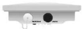
√ BEC 4G/LTE Outdoor Router (ODU)
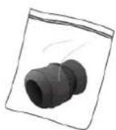
√ M25 Cable Gland
√ This Quick Installation Guide
√ Outdoor LAN Cable
√ Gigabit
Power-over-Ethernet
(PoE) Injector
√ Grounding Cable
√ Mounting Kit
LTE Outdoor CPE
M25 Cable Gland
Quick Start Guide
(This document)

25ft Outdoor
LAN Cable

natural_image
Yellow cable with two connectors, no text or symbols visibleGigabit PoE Injector

natural_image
Black electronic device with attached black cable and two connectors (no visible text or symbols)Ground Cable

natural_image
Simple line drawing of a coiled cable and a plug with a valve, no text or symbols presentMounting Kit
(#RT4R)


Articulation Pole x 1
T-formed Bracket x 1
M8x40
Screw Bolt x 1
M8 Nut x 1
Washer
M8 x 1
M6 x 4
Spring Washer
M8 x 1
M6 x 4


M6x16
Screw x 4
Wood Screw x 4
Wood / Gyprock Plug x 4
W-Bar × 1
M6x60
Screw Bolt x 2
M6 Washer x 2
Spring Washer x 2
Stainless
Hose Clamp 1"-3" x 2

Attention
- Do not remove, open, or repair the case yourself. Contact with your Internet Service Provider or have it repaired at a qualified service center.
- Use the supplied PoE (Power-over-Ethernet) injector for indoor only or with any 802.3at capable PoE injectors to connect to the device.
- It is mandatory to earth ground the device. Improper grounding not only could damage the unit but also all equipment connected to it.
Hardware Overview

| CONNECTORS | DESCRIPTION |
| SIM / LED / Reset | Insert the SIM card into the SIM slot.Press the reset button to reset device or restore to factory default settings |
| Gigabit LAN(PoE) | Connect the supplied PoE injector, 802.3at compliant, using an Ethernet cable. |
| LED | STATUS | DESCRIPTION |
| 1. Power | Orange | System is either in initial startup phase or has boot failure |
| Green | System is up and ready | |
| Off | No input power | |
| 2. LAN(PoE) | Orange | Transmission speed is at 10/100Mbps |
| Green | Transmission speed is at gigabit speed (1000Mbps) | |
| Blinking | Data being transmitted/received | |
| Off | No device is being connected | |
| 3. Internet | Orange | IP request failed or system is in initial booting phase |
| Green | IP connected and traffic is passing thru the device | |
| 4. 4G/LTE Signal Strength | Green | RSSI greater than -69 dBm. Excellent signal condition |
| Green Flashing quickly | RSSI from -81 to -69 dBm. Good signal condition | |
| Orange Flashing quickly | RSSI from -99 to -81 dBm. Fair signal condition | |
| Orange Flashing slowly | RSSI less than -99 dBm. Poor signal condition | |
| Orange | No signal. 4G/LTE module is still in connected mode | |
| Off | No 4G/LTE module or 4G/LTE module has failed |
Mounting Kit Installation
Mounting Kit includes:
- Articulation Pole x 1
- T-formed Bracket x 1
- M8x40 Screw Bolt x 1
- M8 Nut x 1
- M8 Washer x 1
- M6 Washer x 4
- M8 Spring Washer x 1
- M6 Spring Washer x 4
- M6x16 Screw x 4


M8 Nut x 1

M8 Washer x 1
M6 Washer x 4

Spring Washer M8 x 1
Spring Washer M6 x 4
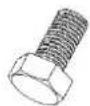
M6 x 16 Screw x 4
For Wall Mount Installation, you will need:
- Wood Screw x 4
- Wood / Gyprock x 4
For Pole Mount Installation, you will need:
- W-Bar x 1
- Stainless Hose Clamp x 2
- M6 x 60 Screw Bolt x 2
- M6 Washer x 2
- Spring Washer x 2


W-Bar x 1

Stainless Hose Clamp 1"\~3" x 2

M6 x 60 Screw Bolt x 2

M6 Washer x 2

Spring Washer M6 x 2
1. Attach the Articulation Pole to the Enclosure
Attach the articulation pole to the back of the BEC 4G/LTE ODU enclosure using the supplied M6 screws, M6 spring washers and M6x16 screws which are included in the mounting kit.

Tool Advice : Use #10 HEX. Wrench to tighten or loosen the bolt(s).
Note: The flexible mounting kit can be adjusted in multiple angles to align with the base station for higher efficiency.
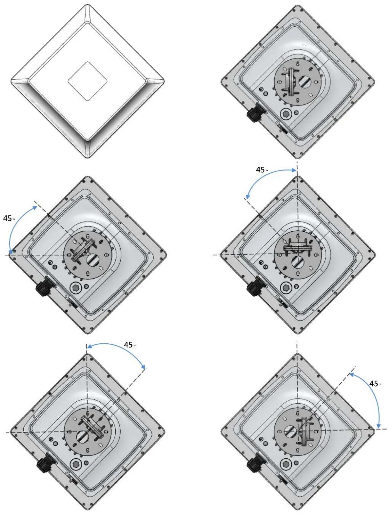
2. Wall or Pole Mount Installation
Mounting on Wall
Fix the T-formed Bracket to the wall by using wood screws and Gyprock plugs.

Mounting on a Pole between 1.5" to 2" (38.1\~50.8mm)
Attach the T-formed Bracket and the W-bar to the pole then use M6x60 bolts, M6 spring washers and M6 washers to fix the mounting kit onto the pole.


(a) The accept pole diameter is from 1.5" to 2". If the diameter is larger than 2", it can cause a failure extremely fast. If diameter is smaller than 1.5", the clamping force might be insufficient in holding the device to the pole.

(b) To minimize bolts crosstalk, the bolt should gradually increase the bolt load on both sides.
Mounting on a Pole between 1" to 3" (25.4\~76.2mm)

natural_image
Technical diagram of a cylindrical mechanical component with red arrows indicating motion or force direction (no text or symbols)Use the stainless hose clamps through the T-formed Bracket.

natural_image
Mechanical assembly diagram showing a cylindrical component with attached parts and red arrows indicating motion direction (no text or symbols)Fix the T-formed Bracket to the pole by using the supplied stainless hose clamps. Use a flat-head screwdriver to turn the head of the screw clockwise to tighten it.
3. Attach the BEC 4G/LTE ODU Enclosure to the Pole
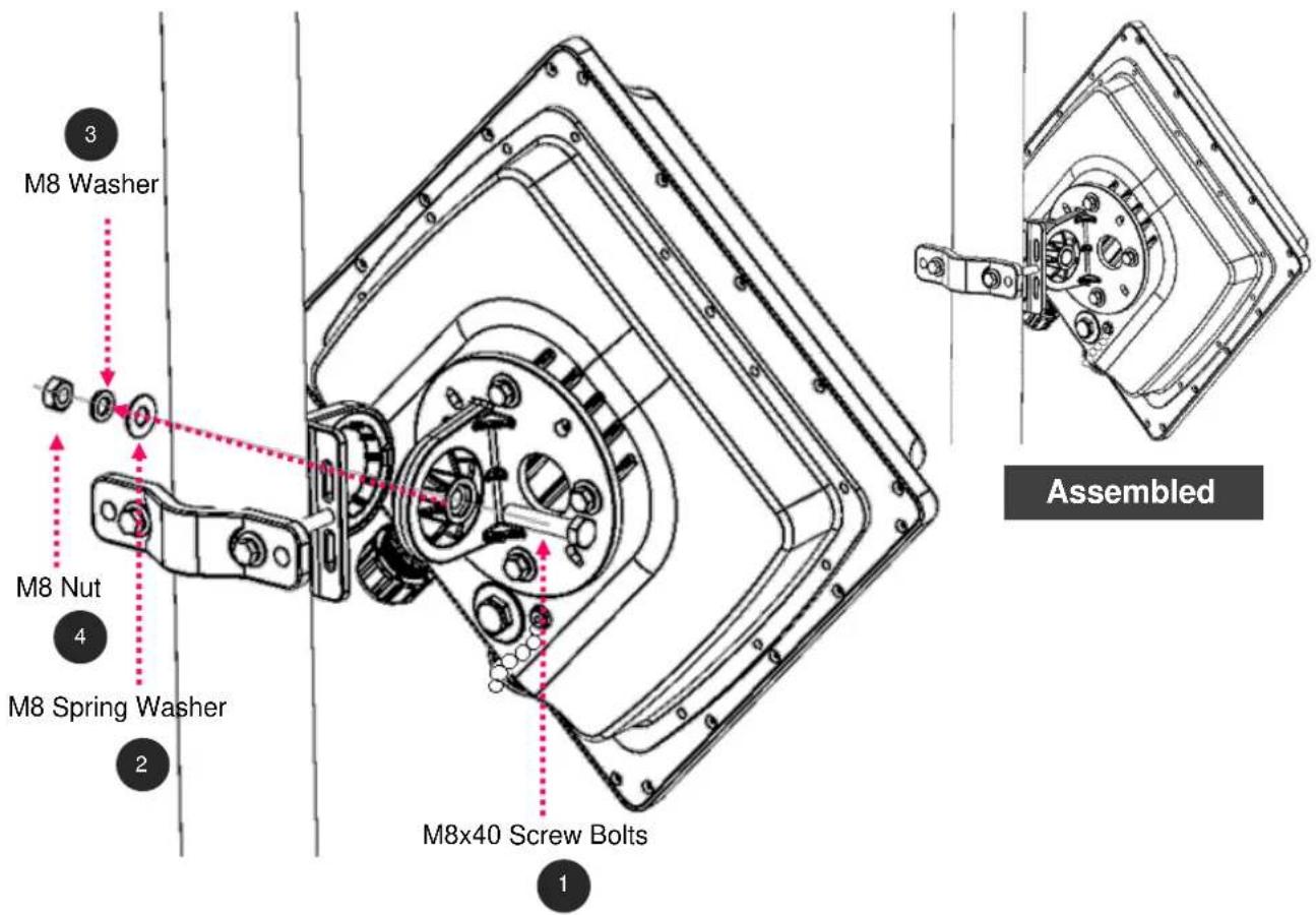
Attach the articulation pole (the BEC 4G/LTE ODU enclosure) to the T-formed bracket using the supplied M8 nut, M8 spring washer, M8 washer and M8x40 screw bolts.
4. Proper Grounding to Complete the Installation
Attach the grounding wire to the BEC 4G/LTE ODU and tighten the screw

5. Position Adjustment
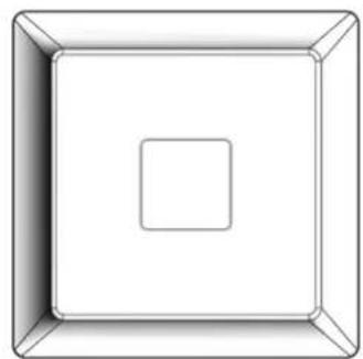
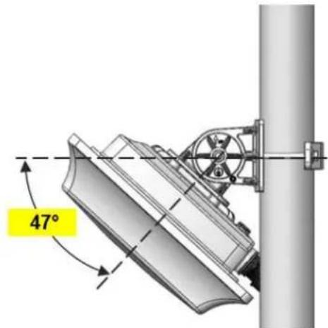
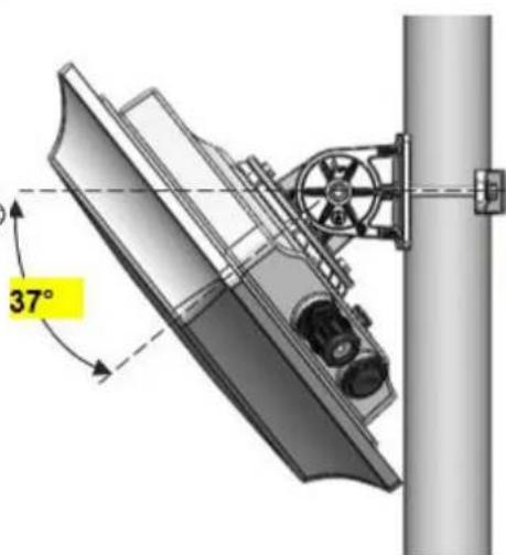
Adjust the BEC 4G/LTE ODU until it reaches the desire elevation and depression angle, then tight the M8 nut (see Attach the BEC 4G/LTE ODU Enclosure to the Pole for more information)
natural_image
Simple 3D diagram of a square centered within a rounded square (no text or symbols)Max. upward angle: 47^
Max. downward angle: 47°


natural_image
Pure geometric diagram of nested squares with no text or symbolsMax. upward angle: 37°
Max. downward angle: 37^
natural_image
Technical diagram of a mechanical assembly with a 37-degree angle标注 (no readable text or symbols)
Router Installation Instructions
1. Power on your BEC 4G/LTE ODU
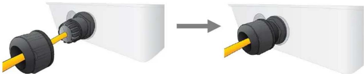
Step 1: Assemble M25 cable gland

A

B

C


D
Step 2: Unscrew the LAN (PoE) cap then insert an outdoor Ethernet cable (RJ-45) through material A-D, and then connect the RJ-45 Ethernet cable into the LAN (PoE) port.

Step 3:
3.1: Insert Ⓐ at the back end of Ⓓ
3.2: clip Ⓑ on Ⓒ
3.3: keep Ⓑ close to Ⓓ
3.4: then tighten Ⓐ.
natural_image
Diagram showing a plug inserted into a housing, before and after assembly (no text or symbols)Step 4:
Insert the other end of outdoor Ethernet cable (RJ-45) to the supplied Gigabit PoE injector Data+Power port. Connect another Ethernet cable (RJ-45) directly to the Data port and the other end of cable to a switch or broadband router.
IMPORTANT: It is recommended to put the Gigabit PoE Injector on an UPS or Surge Protector. Use a grounding wire to ground your BEC 4G/LTE ODU is REQUIRED!

flowchart
graph TD
    A["PC / Laptop"] --> B["6300NXL"]
    B --> C["POE injector"]
    C --> D["Electrical outlet"]
    D --> E["LTE Outdoor CPE"]
    E --> F["Ground Cable"]
    C --> G["Data"]
    C --> H["Data+Power"]
    style A fill:#f9f,stroke:#333
    style B fill:#ccf,stroke:#333
    style C fill:#cfc,stroke:#333
    style D fill:#fcc,stroke:#333
    style E fill:#cff,stroke:#333
    style F fill:#ffc,stroke:#333
    style G fill:#cfc,stroke:#333
    style H fill:#fcc,stroke:#333
2. Set up your 4G/LTE Internet Connection
Step 1: Unscrew the cap of SIM card slot.

Step 2: Slide the SIM card with the mental contacts (gold plate) facing down to the SIM slot then push it all the way in until you hear the clicking sound.

It is recommended to use an industrial-grade SIM card.
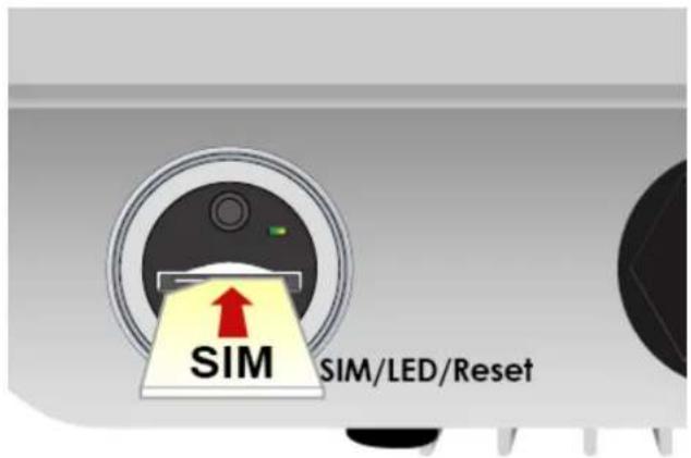
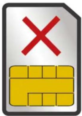
Step 3: Screw the cap back tightly.
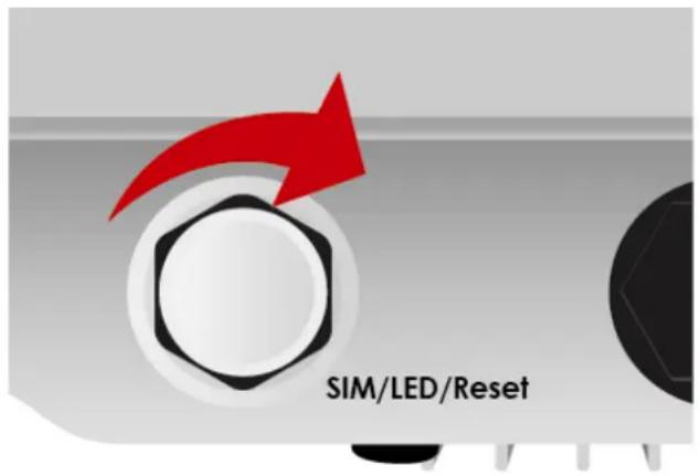

Please power off the device before inserting or removing the SIM card.
Step 4: Login to your BEC 4G/LTE ODU
The default IP of the router is 192.168.1.254 with subnet 255.255.255.0. Make sure the attached PC to this router is in the same subnet and has an IP address in the range between 192.168.1.1 \~ 192.168.1.253.
Open a web browser and type http://192.168.1.254 in the URL address bar.
URL Address bar: type http://192.168.1.254
http://192.168.1.254/

The login prompt will appear. Input the default username (admin) and password (admin) for Account type, Administrator. *This username / password may vary by different Internet Service Providers.
Please see the relevant sections of user manual for detailed instructions on how to configure your BEC 4G/LTE ODU.
Step 5: Use the Quick Start wizard for fast Internet connection setups.
5.1 Change administration password: Setup a new password for "admin" account for device management. The default password is "admin". Click Continue to go on to the next step.
*The password may vary by different Internet Service Providers.
New Password: assign a new, unique password
Confirm Password: re-enter the new password again
Next Step: click Next
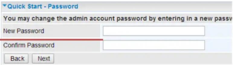
5.2 Time Zone Configuration: Enable and select your Time Zone then click Continue to go on to the next step

5.3 4G/LTE Internet Connection Setup: Fill out all relevant parameters provided by your ISP.
5.4 Saving Configuration Settings: The Setup Wizard has completed. Click BACK to make changes or correct mistakes. Click NEXT to save settings. If the Internet connection is not ready, please double check your 4G/LTE settings again.
Troubleshooting
- None of the LEDs are on when you turn on the Router.
Check the connection between the adapter and the router. If the error persists, you may have a hardware problem. In this case you should contact technical support.
- You have forgotten your Router login and/or password.
Try the default login and password, please refer to User Manual or consult with your Internet Service Provider. If this fails, you can restore your router to its factory settings by holding the Reset button on the back of your router for 6 seconds or more. *This username / password may vary by different Internet Service Providers.
- Can't ping any PCs on the LAN.
Check the LAN (PoE) LED on the Router. The LED should be on for the port that has a PC connected. If it is off, check the cables between your Router and the PC. Make sure you have uninstalled any software firewall for troubleshooting. Verify that the IP address and the subnet mask are consistent between the router and the workstations.
Product Support and Contact Information
Most problems can be solved by referring to the Troubleshooting section in the User Manual. If you have other inquiries or need further technical support, please contact with your Internet Service Provider or visit us at www.bectechnologies.net.
FCC Statement
This equipment has been tested and found to comply with the limits for a Class B digital device, pursuant to Part 15 of the FCC Rules. These limits are designed to provide reasonable protection against harmful interference in a residential installation. This equipment generates, uses, and can radiate radio frequency energy and, if not installed and used in accordance with the instructions, may cause harmful interference to radio communications. However, there is no guarantee that interference will not occur in a particular installation. If this equipment does cause harmful interference to radio or television reception, which can be determined by turning the equipment off and on, the user is encouraged to try to correct the interference by one or more of the following measures:
♦ Reorient or relocate the receiving antenna.
- Increase the separation between the equipment and receiver.
- Connect the equipment into an outlet on a circuit different from that to which the receiver is connected.
- Consult the dealer or an experienced radio/TV technician for help.
FCC Caution:
This device complies with Part 15 of the FCC Rules. Operation is subject to the following two conditions:
(1) This device may not cause harmful interference
(2) This device must accept any interference received, including interference that may cause undesired operation.
Any changes or modifications not expressly approved by the party responsible for compliance could void the user's authority to operate this equipment. This device and its antenna(s) must not be co-located or operating in conjunction with any other antenna or transmitter.


- 4G/LTE-Advanced Pro Outdoor Router
- Package Contents
- Hardware Overview
- Mounting Kit Installation
- Mounting Kit includes:
- For Wall Mount Installation, you will need:
- For Pole Mount Installation, you will need:
- Attach the Articulation Pole to the Enclosure
- Wall or Pole Mount Installation
- Mounting on Wall
- Mounting on a Pole between 1.5" to 2" (38.1\~50.8mm)
- Mounting on a Pole between 1" to 3" (25.4\~76.2mm)
- Attach the BEC 4G/LTE ODU Enclosure to the Pole
- Proper Grounding to Complete the Installation
- Position Adjustment
- Router Installation Instructions
- Power on your BEC 4G/LTE ODU
- Set up your 4G/LTE Internet Connection
- Step 4: Login to your BEC 4G/LTE ODU
- Troubleshooting
- Product Support and Contact Information
- FCC Statement
- FCC Caution:
Brand : BEC Technologies
Model : RidgeWave 7000
Category : Router