
LH7500 - Home Automation ZKTeco - Free user manual and instructions
Find the device manual for free LH7500 ZKTeco in PDF.


| Type | Smart Home Controller |
| Dimensions | 100 mm x 100 mm x 25 mm |
| Weight | 200 g |
| Power Supply | 5V DC via USB-C or included adapter |
| Power Consumption | 5 W max |
| Connectivity | Wi-Fi 2.4GHz, Bluetooth 4.2 |
| Supported Protocols | Z-Wave, Zigbee, Matter |
| Voice Assistants | Amazon Alexa, Google Assistant, Apple Siri |
| App Control | ZKTeco Home app (iOS/Android) |
| Scenes & Automation | Custom schedules and triggers |
| Remote Access | Via cloud, requires internet |
| Maximum Connected Devices | Up to 100 |
| Range | 30 m indoors (Z-Wave/Zigbee) |
| Indicator | Multi-color LED for status |
| Security | AES-128 encryption, secure boot |
| Operating Temperature | 0°C to 40°C |
| Humidity | 10% to 90% non-condensing |
| Mounting | Tabletop or wall mount (included) |
| Maintenance | Wipe with dry, soft cloth |
| Repairability | User-replaceable power adapter; other parts require technician |
| Spare Parts | Power adapter available as accessory |
Frequently Asked Questions - LH7500 ZKTeco
User questions about LH7500 ZKTeco
0 question about this device. Answer the ones you know or ask your own.
Ask a new question about this device
Download the instructions for your Home Automation in PDF format for free! Find your manual LH7500 - ZKTeco and take your electronic device back in hand. On this page are published all the documents necessary for the use of your device. LH7500 by ZKTeco.
USER MANUAL LH7500 ZKTeco
natural_image
Two white line drawings of a door handle and circular base on green background (no text or symbols)Before Installation
Lock Diagram
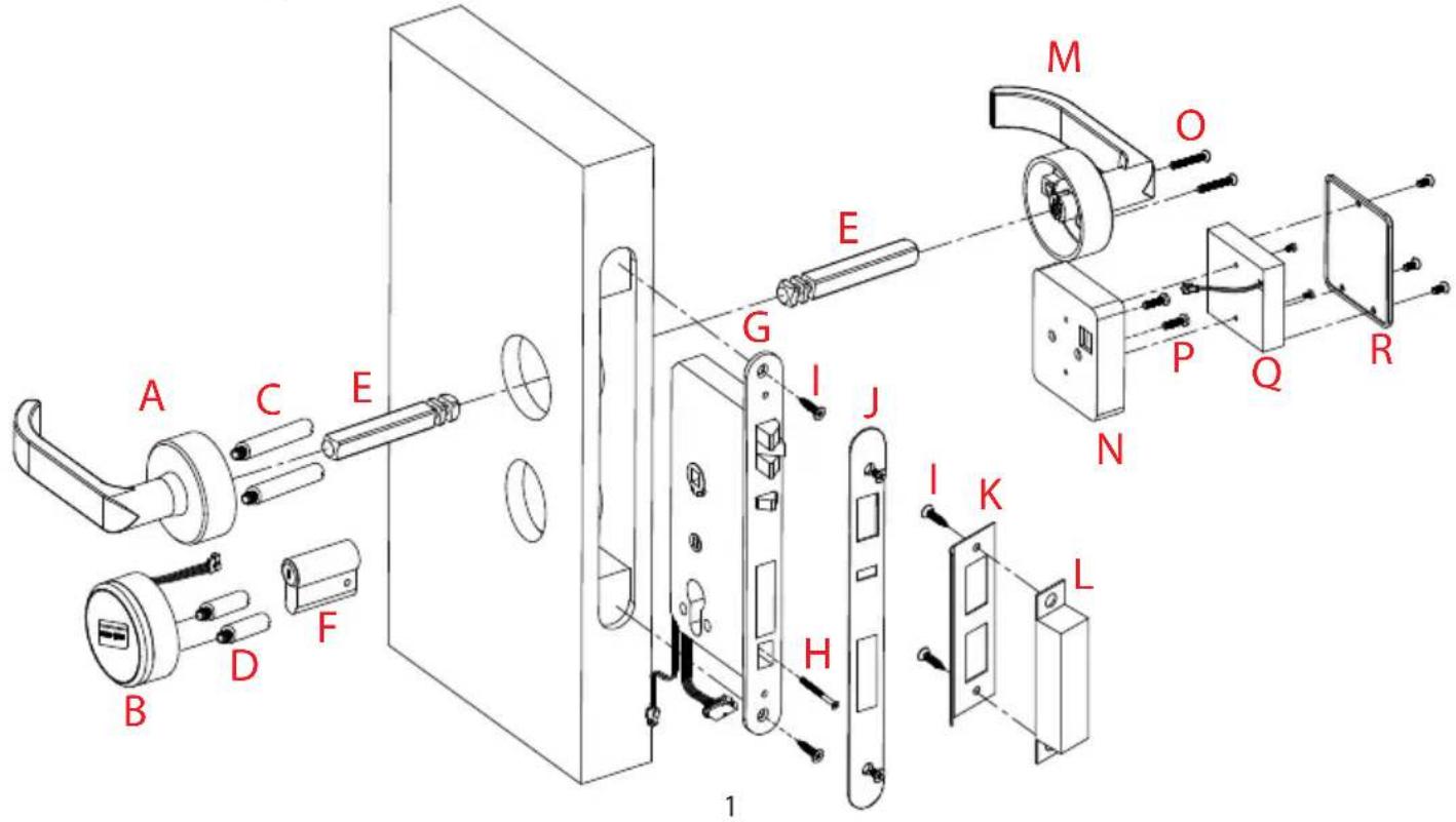
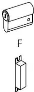
In the Box
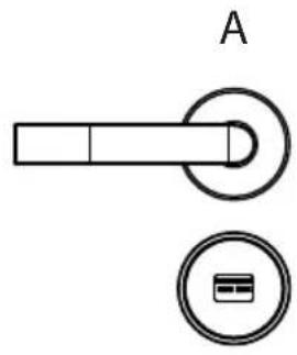
natural_image
Pure electrical circuit lines without any symbolsB
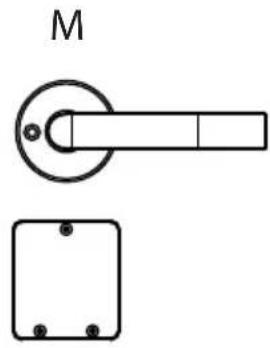
natural_image
Technical line drawing of a door handle and a square bracket (no text or symbols)N
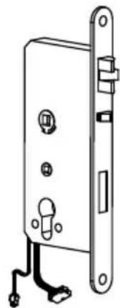
natural_image
Technical line drawing of a door lock with handle and clasp (no text or symbols)G

K
natural_image
Two technical line drawings of cylindrical components, one with a flanged top and the other with a rectangular base (no text or symbols)L
S
C
D
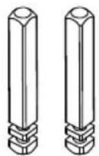
E
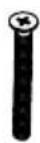
H
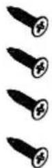
|
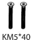
O

PM4*20
P
U
Before you begin
1. Preparing door
| Door Thickness O | Screws P Screws | |
| 38 - 48 mm 40 mm | 20 mm |
Note: If the door is thicker than 38-48 mm, this lock will not be available.
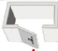
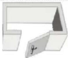
2. Determining Handing
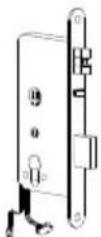
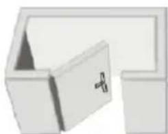
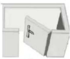
The hand of a door is determined from the secure side of the door. The term "secure" means the side from which you unlock and enter.
G
natural_image
Abstract 3D geometric shape with no visible text or symbolsLeft hand, open inward
natural_image
Illustration of a white office desk with a door and a lamp (no text or symbols)Right hand, open inward
G
G
natural_image
3D diagram of a mechanical part with a highlighted section and red dot (no text or symbols)Left hand, open outward
natural_image
Simple 3D diagram of a mechanical part with no visible text or symbolsRight hand, open outward
G
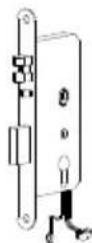
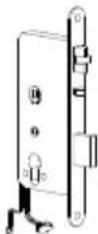
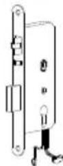
Note: Please install the mortise (G) according to the above pictures.
Cautions
- New lock is defined as always open mode until it was unlocked once by mifare card.
- Please swipe authorised card, time sync card, room card at first for the new lock.
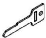
- The lock is equipped with mechanical keys for manual unlocking. Remove the mechanical keys from the package and keep them in a safe place.
- To power on the lock, four alkaline AA batteries (not included) are required. Non-alkaline and rechargeable batteries ARE NOT RECOMMENDED.
- Do not remove batteries when the lock is in working state.
- When battery power is low, the lock will beep to remind user to renew the batteries. Please do not mix up positive and negative while replacing battery.
- Avoid contacting with corrosive substances, and do not hang objects on the handle.
- The software within the lock manages the RFID cards, for more details refer to the software user manual.
- If there are any questions, please do not hesitate to contact the seller.
Installation
1. Drill holes on the door
door thickness
38\~48 mm
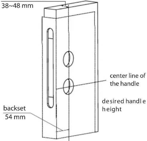
Note 1: Align the template along the vertical center line of the mortise (G) at the desired handle height, and tape it to door.
Note 2: Mark the holes first, then start drilling.
2. Remove the mortise latch plate
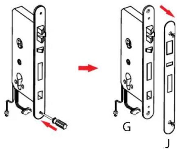
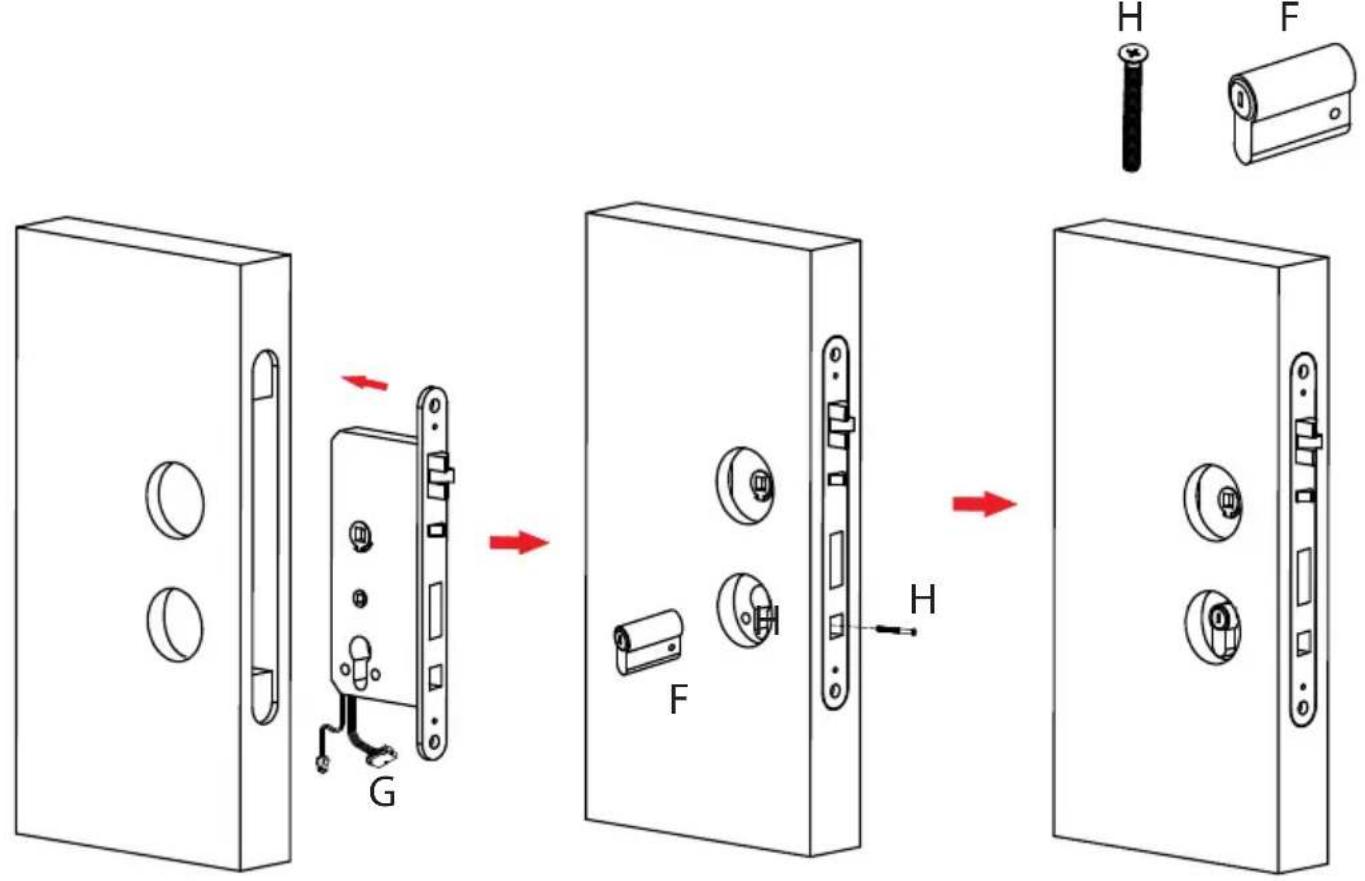
- Install mortise(G) and cylinder(F)
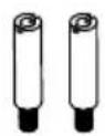
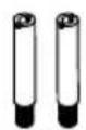
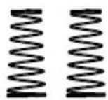
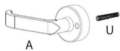
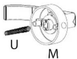
4. Install the coil spring and screw the stud
natural_image
Technical line drawing of a mechanical component labeled A and U (no text or symbols on the diagram itself)
natural_image
Technical line drawing of a mechanical component with labeled parts U and M (no text or symbols beyond labels)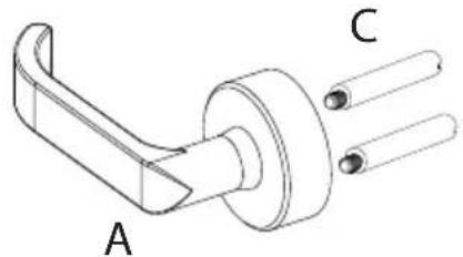
natural_image
Technical line drawing of a mechanical component with labeled parts A and C (no text or symbols beyond labels)
natural_image
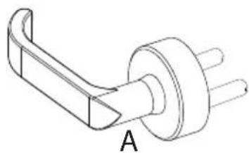
Technical line drawing of a mechanical component with labeled point A (no text or symbols beyond label)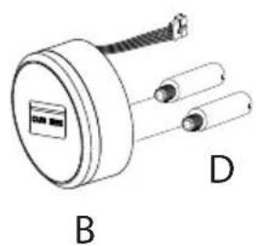
natural_image
Technical line drawing of a mechanical component with labeled parts B and D (no text or symbols on the diagram itself)
natural_image
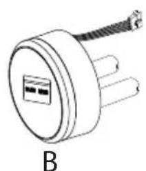
Technical line drawing of a mechanical component with a labeled section B (no text or symbols on the diagram itself)5. Install exterior panel (A)
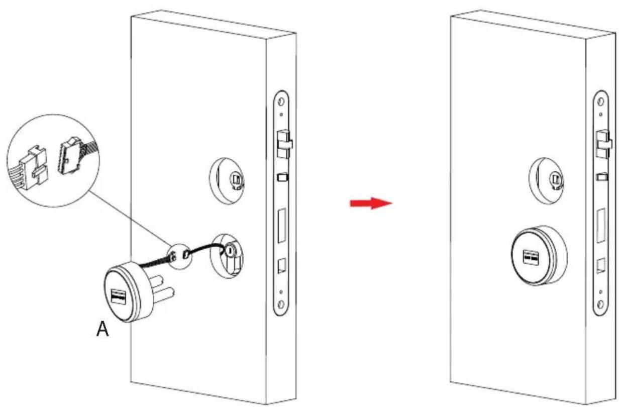
6. Install in Nterior panel ()
P

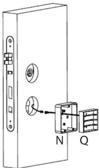
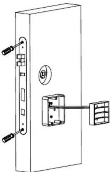
natural_image
Technical line drawing of a door with lock and wall-mounted components (no text or symbols)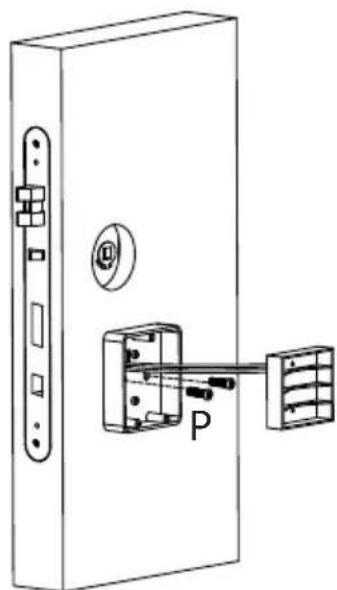
natural_image
Technical line drawing of a door lock assembly with handle and keyway (no text or symbols)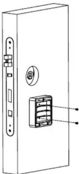
natural_image
Technical line drawing of a door lock with a close-up view showing internal components (no text or symbols)7. Fix with the mortise(G)
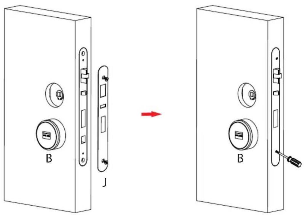
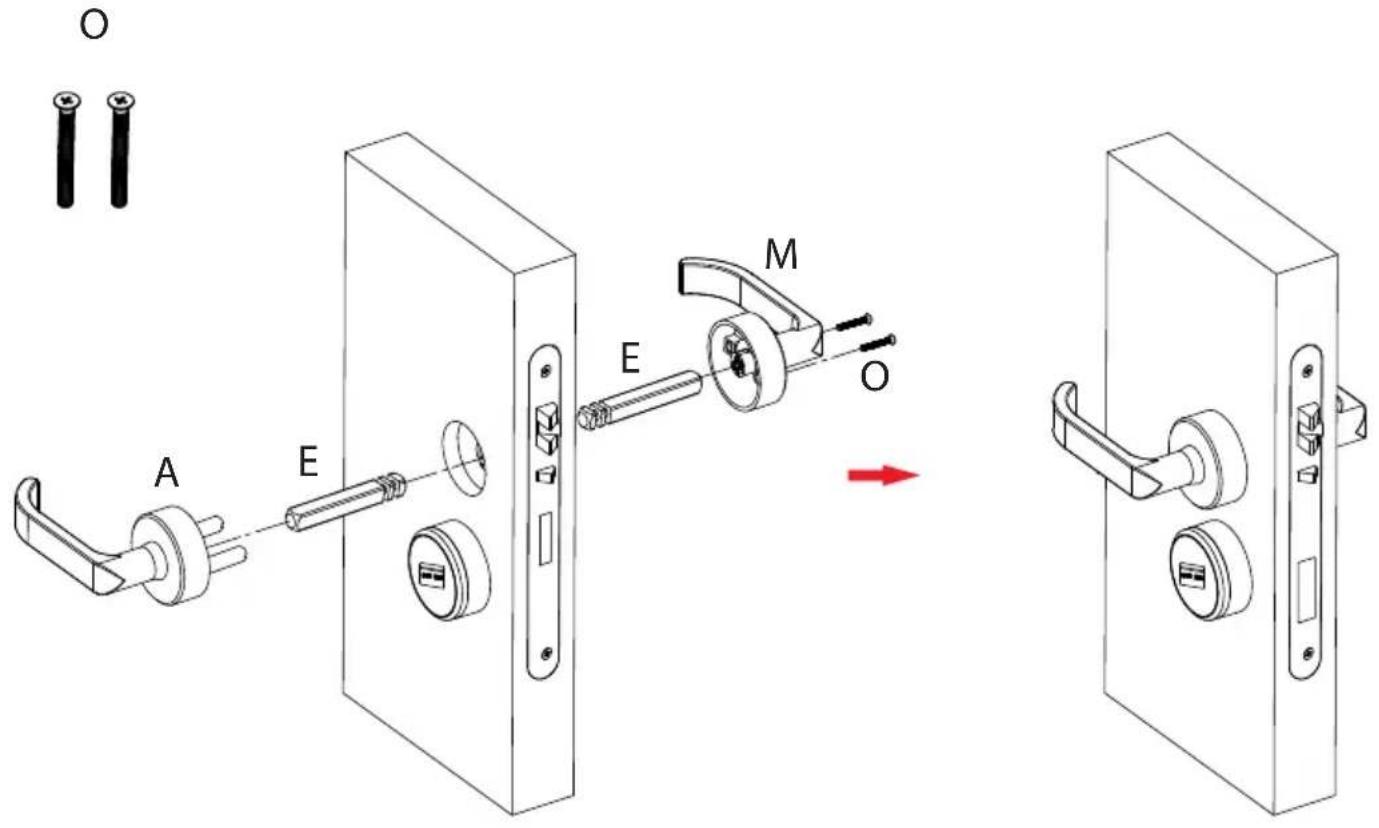
8. Mount handles
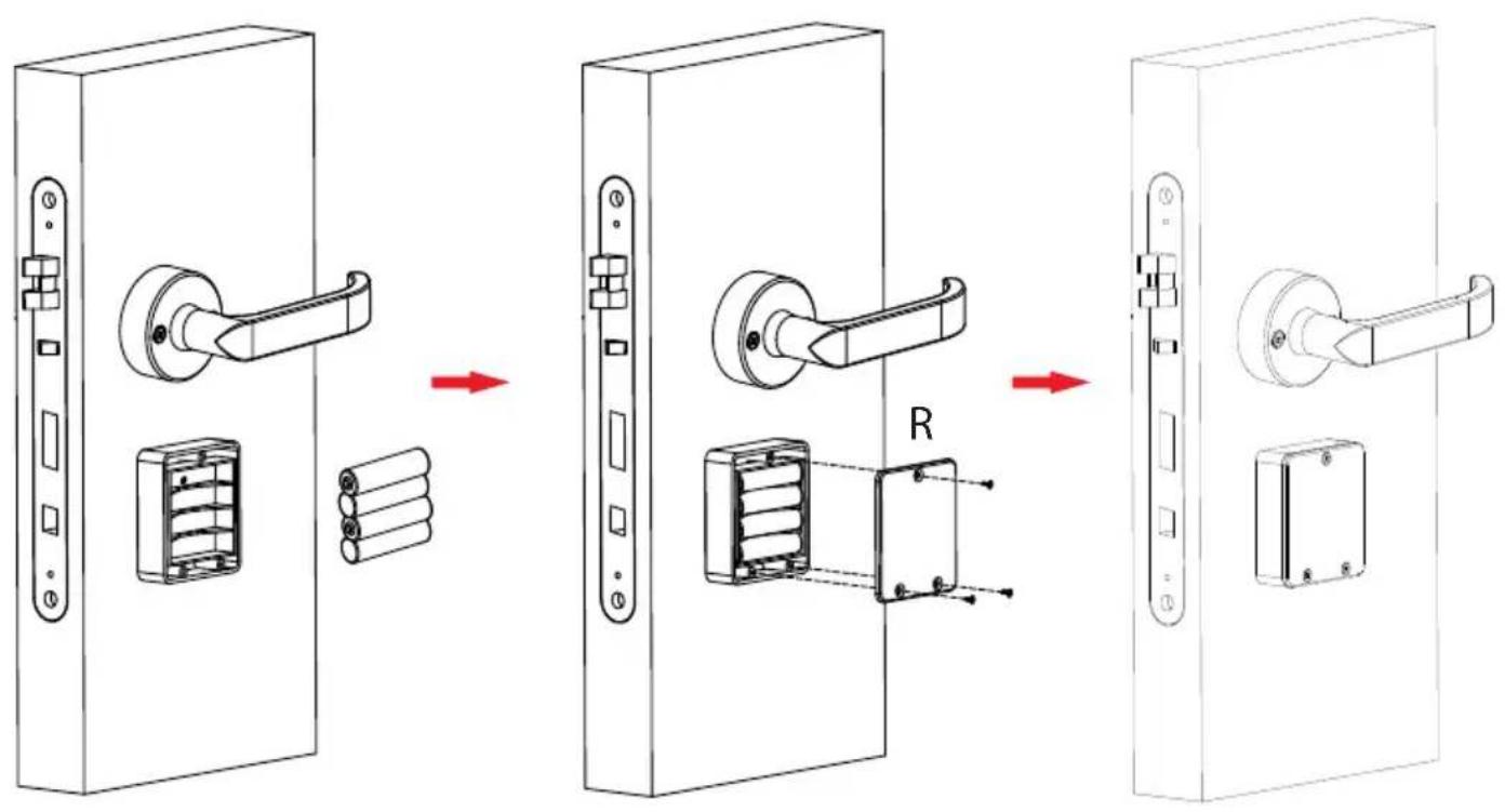
9. Install the battery
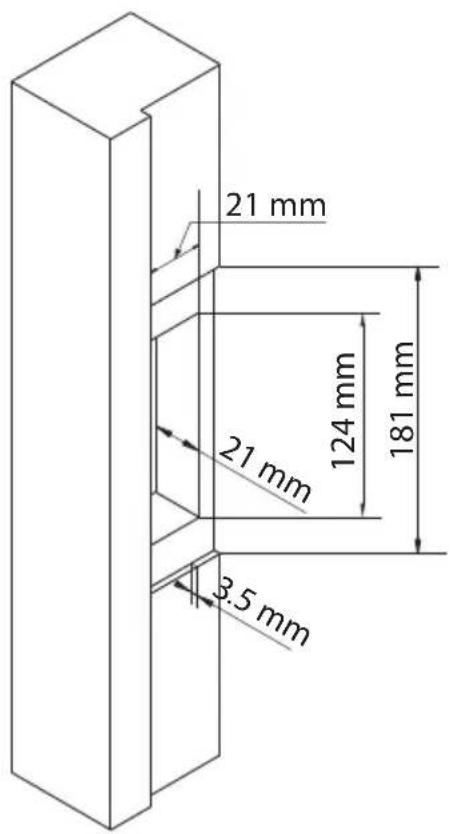
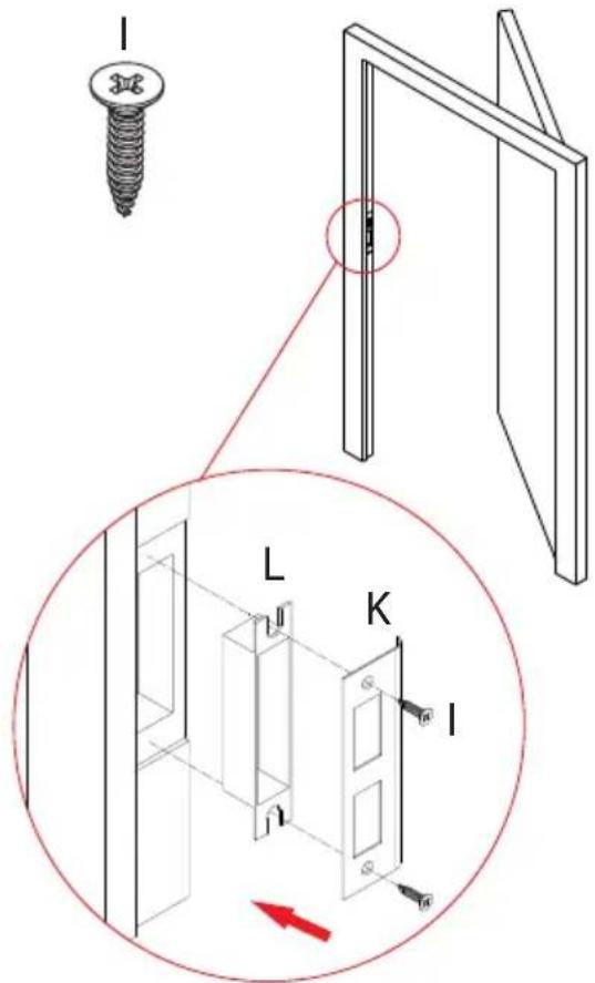
10. Mark and drill holes for strike
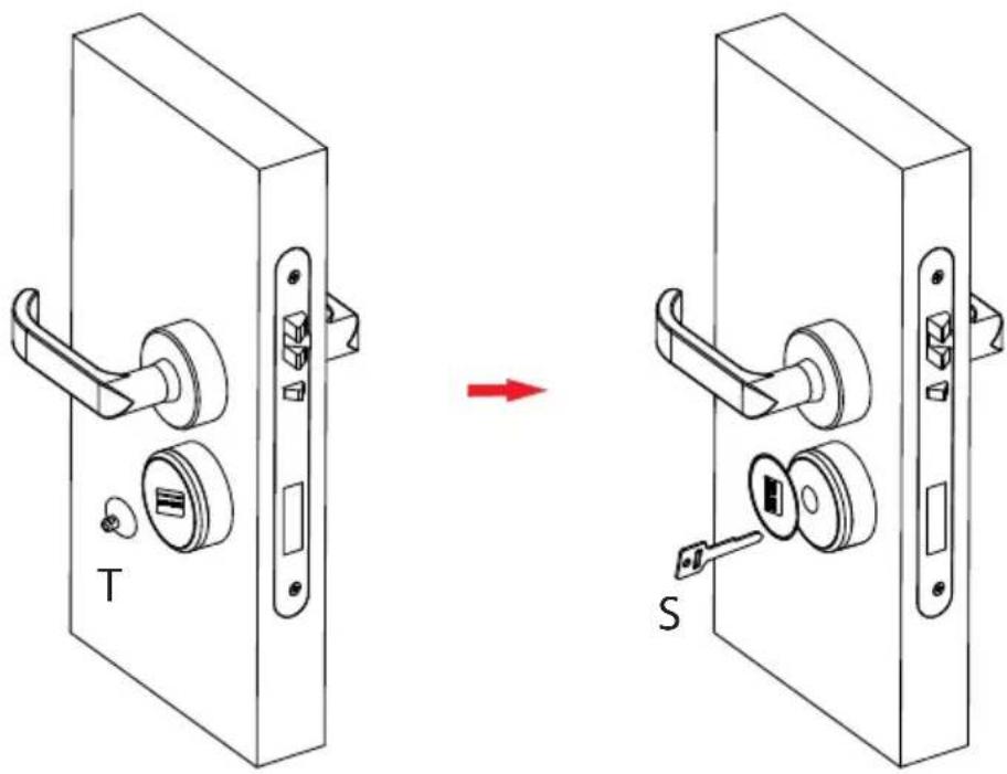
11. Test Lock by mechanical key (S)
Step1: Remove the cover on the key hole with a sucker(T).
Step2: Insert mechanical key (S) into the key hole and rotate it at 90°.
www.zkteco.eu

© Copyright 2017. ZKTeco Inc. ZKTeco Logo is a registered trademark of ZKTeco or a related company. All other product and company names mentioned are used for identification purposes only and may be the trademarks of their respective owners. All specifications are subject to change without notice. All rights reserved.
- Before Installation
- Lock Diagram
- Before you begin
- Preparing door
- Determining Handing
- Cautions
- Installation
- Drill holes on the door
- Remove the mortise latch plate
- Install the coil spring and screw the stud
- Install exterior panel (A)
- Install in Nterior panel ()
- Fix with the mortise(G)
- Mount handles
- Install the battery
- Mark and drill holes for strike
- Test Lock by mechanical key (S)
Brand : ZKTeco
Model : LH7500
Category : Home Automation