
OCF501 - Optical sensor IFM - Free user manual and instructions
Find the device manual for free OCF501 IFM in PDF.


| Product Type | Fibre-optic sensor |
| Model | OCF501 |
| Brand | IFM |
| Intended Use | Non-contact detection of objects via fibre optics (diffuse or through-beam) |
| Dimensions | Approx. 30 x 60 x 80 mm (DIN rail mount) |
| Weight | Approx. 50 g |
| Power Supply | 18-30 V DC, SELV/PELV, Class 2 (cULus) |
| Electrical Connection | M8 connector or cable, 4-pin (BK, BN, BU, WH) |
| Outputs | 2 switching outputs (OUT1, OUT2), PNP/NPN configurable, IO-Link |
| Operating Modes | HIGH SPEED, FAST, STANDARD, FINE, POWER, HIGH POWER |
| Response Time | 25 µs (HIGH SPEED) to 12.5 ms (HIGH POWER) |
| Switching Frequency | 20 kHz (HIGH SPEED) to 40 Hz (HIGH POWER) |
| Teach Methods | 2-point, object, background, position, dynamic, window |
| Display | 4-digit LED with bargraph and excess gain views |
| Languages | EN, DE, FR, IT, ES, PT, JA, KO, RU, ZH |
| LED Indicators | Green (power), Yellow (OUT1 switching status) |
| Hysteresis | 1% to 20% (adjustable) |
| Delay Modes | None, ON, OFF, ON & OFF, IMPULSE, ON & IMPULSE |
| Protection | Short circuit protection (LED flashes at 4 Hz) |
| Maintenance | Keep fibre-optic heads clean; do not open housing |
| Safety | Installation by qualified electrician; observe national regulations |
| Reparability | Only by manufacturer |
| Disposal | Environmentally friendly disposal per national regulations |
Frequently Asked Questions - OCF501 IFM
User questions about OCF501 IFM
0 question about this device. Answer the ones you know or ask your own.
Ask a new question about this device
Download the instructions for your Optical sensor in PDF format for free! Find your manual OCF501 - IFM and take your electronic device back in hand. On this page are published all the documents necessary for the use of your device. OCF501 by IFM.
USER MANUAL OCF501 IFM
Operating instructions
Fibre-optic sensor for fibre optics
OCF
Contents
1 Preliminary note 4
1.1 Symbols used 4
2 Safety instructions.... 5
3 Intended use.... 6
4 Function 7
4.1 Measuring principle.... 7
4.2 Operating modes 7
4.2.1 Switching mode.... 7
4.2.2 Operation with IO-Link master.... 7
5 Installation.... 9
5.1 Attaching the fibre optics....9
6 Electrical connection.... 11
6.1 PNP/NPN selection.... 11
7 Operating and display elements 12
7.1 LED states 12
8 Set-up.... 13
8.1 Guided teach / teaching process.... 13
8.1.1 Selecting the [Language] 13
8.1.2 Selecting the [Polarity] 13
8.1.3 Selecting the [Teach method] 13
8.1.4 2-point teach.... 14
8.1.4.1 Teaching an object 14
8.1.4.2 Teaching the background 14
8.1.5 Run mode 14
8.2 Guided teach / extended teaching process 14
9 Menu....15
9.1 Basic functions 15
9.2 Extended functions 16
10 Operation 19
10.1 Operating modes 19
11 Parameter setting 20
11.1 Parameter level basic functions.... 20
11.1.1 [New teach OUT1]. 20
11.1.2 [OUT1 Setpoint1] 20
11.1.3 [OUT1 Setpoint2] 21
11.1.4 [Operating mode] 21
11.1.5 [Fibre optics flashing] 21
11.1.6 [Ext. functions] 21
11.1.7 [Back] 21
11.2 Parameter setting of extended functions 22
11.2.1 [Configuration].... 22
11.2.2 [Output 1] 22
11.2.2.1 [Output function] 22
11.2.2.2 [Mode].... 22
11.2.2.3 [Output logic].... 23
11.2.2.4 [Setpoint1].... 23
11.2.2.5 [Hysteresis] 23
11.2.2.6 [Delay mode].... 23
11.2.2.7 [Back] 24
11.2.3 [Output 2] 24
11.2.4 [Display] 24
11.2.5 [Device info] 25
11.2.6 [Factory setting] 25
11.2.7 [Back] 25
11.3 Submenu [Configuration] CFG 25
11.3.1 [Polarity] 25
11.3.2 [Transmitter LED] 25
11.3.3 [Transmitter intensity] 26
11.3.4 [Smart mode] 26
11.3.5 [Operating mode] 26
11.3.6 [Auto SP tracking] 26
11.3.7 [Fibre optics flashing] 27
11.3.8 Restart guide.... 28
11.3.9 [Back] 28
11.4 Submenu [Display] DIS.... 28
11.4.1 [Language] 28
11.4.2 [Layout].... 28
11.4.3 [Scheme].... 29
11.4.4 [Brightness] 29
11.4.5 [Orientation] 30
11.4.6 [Back] 30
12 Setting.... 31
12.1 Setting the range.... 31
12.1.1 Single point mode 31
12.1.1.1 SP1 Two Point teach. 31
12.1.1.2 SP1 Teach on object.... 31
12.1.1.3 SP1 Teach on background 32
12.1.1.4 SP1 Teach on position 32
12.1.1.5 SP1 Dynamic teach.... 32
12.1.2 Window mode 33
12.1.2.1 SP1 Two Values teach 33
13 Maintenance, repair and disposal 34
14 Factory setting 35
1 Preliminary note
You will find instructions, technical data, approvals and further information using the QR code on the unit / packaging or at www.ifm.com.
1.1 Symbols used
√ Requirement
Instructions
Reaction, result
[...] Designation of keys, buttons or indications
→ Cross-reference

Important note
Non-compliance may result in malfunction or interference.

Information
Supplementary note
2 Safety instructions
- The unit described is a subcomponent for integration into a system.
– The system architect is responsible for the safety of the system.
- The system architect undertakes to perform a risk assessment and to create documentation in accordance with legal and normative requirements to be provided to the operator and user of the system. This documentation must contain all necessary information and safety instructions for the operator, the user and, if applicable, for any service personnel authorised by the architect of the system.
- Read this document before setting up the product and keep it during the entire service life.
- The product must be suitable for the corresponding applications and environmental conditions without any restrictions.
- Only use the product for its intended purpose (→ Intended use).
- If the operating instructions or the technical data are not adhered to, personal injury and/or damage to property may occur.
- The manufacturer assumes no liability or warranty for any consequences caused by tampering with the product or incorrect use by the operator.
- Installation, electrical connection, set-up, operation and maintenance of the product must be carried out by qualified personnel authorised by the machine operator.
- Protect units and cables against damage.
3 Intended use
The fibre-optic sensor is used to connect fibre optics of the FE-11, FT-11, FE-00 and FT-00 type. The E21327 adapter is required for the FE-00 and FT-00 types. The range or sensing range varies depending on the fibre optics used.
Objects and materials can be detected without contact via the fibre optics. The fibre-optic sensor evaluates the signal and outputs a corresponding switching signal.
4 Function
Depending on the fibre optics connected, the fibre-optic sensor can be used as an energetic diffuse reflection sensor or as a through-beam system.
4.1 Measuring principle
Energetic diffuse reflection sensor
| Diffuse sensor The transmitter and receiver are integrated in the same sensing head.The objects are detected by reflection of the light beam based on the energetic, the triangulation or the time-of-flight principle.Energetic principle:The range depends on the energy of the reflected light. Depending on the object surface the light is reflected more or less well:good reflection: smooth / light object.poor reflection: rough / dark object. |  |
| 1: Transmitter and receiver2: Object |
Through-beam system
| Through-beam sensor The transmitter and | receiver are integrated in different fibre-optic heads. The objects are detected by interruption of the light beam. | 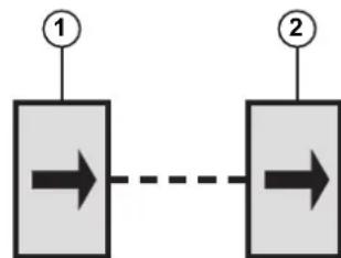 |
| 1: Transmitter2: Receiver |
4.2 Operating modes
4.2.1 Switching mode
In switching mode, the sensor is directly connected to the process control unit and transmits the state via the switching output.

If the set switching threshold is exceeded/not reached, this is signalled by means of switching signals on the switching output.
4.2.2 Operation with IO-Link master
If the sensor is connected to an IO-Link master, parameter setting and data recording can be done completely via IO-Link.
IO-Link is a communication system for the connection of intelligent sensors and actuators to automation systems. IO-Link is regulated in the IEC 61131-9 standard.

General information about IO-Link can be found at io-link.ifm.

The Input Output Device Description (IODD) with all parameters, process data and detailed descriptions of the device can be found at documentation.ifm.com.
IO-Link offers the following advantages:
- Noise immune transmission of all data and process values
- Parameter setting during operation or default setting outside the application
- Parameters to identify the connected devices in the plant
• Additional parameters and diagnostic functions
• Automatic backup and restore of parameter sets in case of device replacement (data storage) - Logging of parameter sets, process values and events
- Device description file (IODD – Input Output Device Description) for easy configuration
- Standardised electrical connection
- Remote maintenance
5 Installation
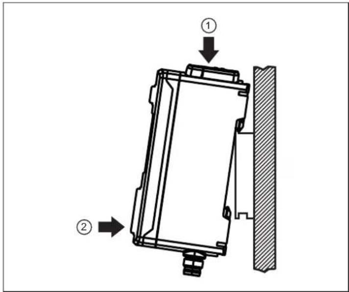
▶ Hook the device into the DIN rail (1) and clip it into place (2) or fix it by means of a mounting bracket (E21328).

The device can be removed from the DIN rail by hand. Installation and removal are independent of the direction.
5.1 Attaching the fibre optics

1: Sensor hole for fibre optics (receiver)
2: Sensor hole for fibre optics (transmitter)
3: Release button
Installation:
▶ Insert the fibre optics into the corresponding sensor hole (1) / (2) until the end stop.

The E21327 adapter is required for the FT-00 and FE-00 fibre optics with screw adaption.
Removal:
▶ Press the release button and remove the fibre optics.
6 Electrical connection

The device must be connected by a qualified electrician.
▶ Observe the national and international regulations for the installation of electrical equipment.
▶ Ensure voltage supply according to SELV, PELV. OCFxxx: cULus, Supply Class 2
▶ Disconnect power.
▶ Connect the device as follows:
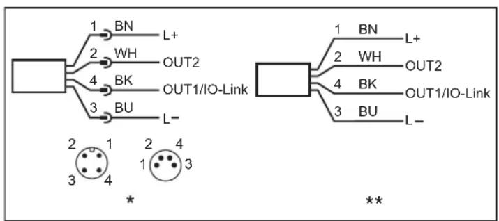
Fig. 1: Wiring diagram (colours to DIN EN 60947-5-2)
* Device types with M8 connector, ** Device types with cable connection
BK: Black BN: Brown
BU: Blue WH: White
6.1 PNP/NPN selection
Pins 2 and 4 can be switched between PNP and NPN logic.
The setting cannot be made for individual pins, but applies to all pins.
7 Operating and display elements

1: 1x green LED
- Power LED
2: 1x yellow LED
- Switching status OUT1
3: Button [●]
- Selection and confirmation of parameter values
4: Display
- Display of process values and menu
5: Button [▼]
- Setting of parameter values (scrolling by holding pressed, incrementally by pressing once)
6: Button [▲]
- Setting of parameter values (scrolling by holding pressed, incrementally by pressing once)

The programming buttons can be locked and unlocked with the following step: Keep [▲] + [▼] pressed for 10 s.

Pressing the [▲] + [▼] buttons at the same time leads back to the menu navigation.
7.1 LED states
| LED behaviour | Description Action | ||
| PWR OUT1 | |||
| PWR LED is green Device is connected to the voltage supply and ready for operation | |||
| PWR LED is green, OUT1 is yellow Device OK, switching output OUT1 active | |||
| PWR LED is green, OUT1 is yellow flashing (4 Hz) | Short circuit on pin 4 or pin 2.Can only be detected if the parameters for OUT1 / OUT2 have been set. | ||

There is no LED for OUT2 on the device. The status of OUT2 is available via IO-Link.
8 Set-up
After installation, electrical connection and parameter setting, check whether the device operates correctly. If the device has been correctly set up, the sensor starts with the "Guided Teach" ( Guided teach / teaching process ☐ 13). The settings made last are internally stored by the sensor.

Switching on after a reset causes the device to activate the "Guided teach", as all the settings have been reset.
8.1 Guided teach / teaching process

flowchart
graph TD
    A["ifm"] --> B["Language"]
    B --> C["Polarity"]
    C --> D["Teach method"]
    D --> E["2 POINT GUIDED BACK"]
    F["4395 Place object and press •"] --> G["4395 Remove object and press •"]
    H["2 Point teach complete"] --> I["Setpoint 4398"]
    J["Installation complete"] --> K["RUN 4395 OUT1"]
    style A fill:#000,stroke:#fff,color:#fff
    style B fill:#FFD700,stroke:#000
    style C fill:#FFD700,stroke:#000
    style D fill:#FFD700,stroke:#000
    style E fill:#FFD700,stroke:#000
    style F fill:#FFD700,stroke:#000
    style G fill:#FFD700,stroke:#000
    style H fill:#FFD700,stroke:#000
    style I fill:#FFD700,stroke:#000
    style J fill:#FFD700,stroke:#000
8.1.1 Selecting the [Language]
▶ Put the sensor into operation.
The available languages are indicated in the display.
▶ Select the required language with [▲] / [▼] and confirm with [●].
8.1.2 Selecting the [Polarity]
Set the switching logic for all outputs
▶ Confirm the parameter with [●] and select one of the options [PNP] / [NPN] using [▲] / [▼].
▶ Confirm your selection by pressing [●].
The switching logic is confirmed.
8.1.3 Selecting the [Teach method]
▶ Confirm the parameter with [●] and select one of the options [2 POINT] / [GUIDED] using [▲] / [▼].
![IFM OCF501 - Selecting the [Teach method] - 1](/content/2026/05/954276/images/ddc14b5fabcbf316390d85df75df94ccdfefdae766d56706e7ede20b7baf0e20.jpg)
▶ For quick teaching, select [2 POINT].
For extended teaching, select GUIDED. (→ Guided teach / extended teaching process ☐ 14)
▶ Confirm your selection by pressing [●].
▷ The installation type is confirmed.
8.1.4 2-point teach
8.1.4.1 Teaching an object
▶ In the next step, the object is taught.
The request [Place object and press •] is displayed.
Place the fibre optics so that the object is within the operating range.
▶ Start the teaching process by pressing [●].
The object is taught.
8.1.4.2 Teaching the background
The second step of the teaching process is initiated.
The request [Remove object and press • ] is displayed.
▶ Remove the object and confirm with [•].
▷ Correct teaching is confirmed in the display. [2 Point teach complete] and [Setpoint XYYX] appear alternately.
▷ [Installation complete] appears in the display.
▶ The device changes to Run mode.

Press [●] to change to Run mode more quickly.
8.1.5 Run mode
After set-up via a "Guided teach", the sensor is put to Run mode. The device is now ready for use.


For more display views in Run mode see (→ [Layout] ☐ 28)
8.2 Guided teach / extended teaching process
Further guided setting options are available during the teaching process if [GUIDED] is selected under [Teach method]:
• [Smart mode]: [on] / [off]
- [Operating mode]: ([HIGH POWER], [POWER], [FINE], [STANDARD], [FAST], [HIGHSPEED])
• [Output1 function]: ([SSC1], [SSC2], [OFF])
- [Teach function 1]: ([2 POINT], [OBJEKT], [BACKGROUND], [POSITION], [DYNAMIC], [WINDOW])
• [Output1 logic]: ([HIGH ACTIVE], [LOW ACTIVE])

All settings can be adjusted subsequently via the menu.
9 Menu

▶ Press • to access the menu from Run mode.
9.1 Basic functions

flowchart
graph TD
    A["4395/1753/OUT1"] --> B["New Teach OUT1 2PT"]
    B --> C["2 POINT BACKGROUND OBJECT POSITION DYNAMIC WINDOW BACK"]
    C --> D["OUT1 Setpoint1 7528"]
    D --> E["7528"]
    E --> F["Operating mode STANDARD"]
    F --> G["Flash fiber STOP"]
    G --> H["Extended functions EF >>"]
    H --> I["Back <<"]
    I --> J["Guided teach 2"]
    J --> K["press • to START flashing"]
    K --> L["press • to STOP flashing"]
    L --> M["→"]
    M --> N["→"]
    N --> O["→"]
    O --> P["→"]
    P --> Q["→"]
    Q --> R["→"]
    R --> S["→"]
    S --> T["→"]
    T --> U["→"]
    U --> V["→"]
    V --> W["→"]
    W --> X["→"]
    X --> Y["→"]
    Y --> Z["→"]
    Z --> A
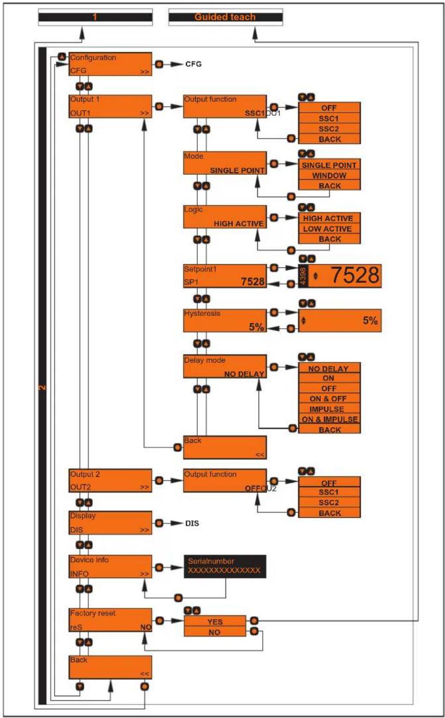
9.2 Extended functions
flowchart
graph TD
    A["Configuration CFG"] --> B["Output 1 OUT1"]
    B --> C["Output function SSC1 DU1"]
    C --> D["Mode SINGLE POINT"]
    D --> E["Logic HIGH ACTIVE"]
    E --> F["Setpoint1 SP1 7528"]
    F --> G["Hysteresis 5%"]
    G --> H["Delay mode NO DELAY"]
    H --> I["Back"]
    I --> J["Output 2 OUT2"]
    J --> K["Display DIS"]
    K --> L["Device info INFO"]
    L --> M["Factory reset reS"]
    M --> N["Back"]
    N --> O["<<"]

    subgraph Guided teach
        P["OFF SSC1 SSC2 BACK"] --> Q["SINGLE POINT WINDOW BACK"]
        R["HIGH ACTIVE LOW ACTIVE BACK"] --> S["SINGLE POINT WINDOW BACK"]
        T["7528"] --> U["7398"]
        V["NO DELAY ON OFF ON & OFF IMPULSE ON & IMPULSE BACK"] --> W["NO DELAY ON OFF ON & OFF IMPULSE ON & IMPULSE BACK"]
        X["OFF SSC1 SSC2 BACK"] --> Y["OFF SSC1 SSC2 BACK"]
    end

[Output 2] must be activated to render its setting options visible.
▶ Confirm the parameter [Output 2] with [•].
▶ Confirm the parameter [Output function] with [●] and set it to SSC1 or SSC2 using [▲/▼].
▶ Confirm the value with [•].
The setting options for [Output 2] become visible and the settings can be made.

When selecting the [WINDOW] mode, the setting option [Setpoint2] also appears under [Output 1] and [Output 2].

flowchart
graph TD
    A["Configuration CFG >>"] --> B["Polarity"]
    B --> C["PNP"]
    C --> D["PNP"]
    C --> E["NPN"]
    C --> F["BACK"]
    B --> G["Transmitter LED ON"]
    G --> H["OFF ON"]
    G --> I["PDOUT BACK"]
    B --> J["Transmitter intensity 100%"]
    J --> K["4398"]
    K --> L["100%"]
    L --> M["Smart mode OFF"]
    M --> N["OFF ON BACK"]
    L --> O["Operating mode STANDARD"]
    O --> P["HIGH SPEED FAST STANDARD FINE POWER HIGH POWER BACK"]
    L --> Q["AutoSPTracking ON"]
    Q --> R["OFF ON BACK"]
    L --> S["Flash fiber >>"]
    S --> T["press to START flashing"]
    S --> U["press to STOP flashing"]
    L --> V["Restart Guide NO"]
    V --> W{No}
    W --> X["Back"]
    X --> Y{<<}
    Y --> Z["Guided teach"]

flowchart
graph TD
    A["Display DIS>>"] --> B["Language"]
    B --> C["4 DIGITS"]
    C --> D["Scheme"]
    D --> E["Brightness"]
    E --> F["Rotation"]
    F --> G["Back"]
    B --> H["ENLanG"]
    H --> I["ENGLISH"]
    H --> J["GERMAN"]
    H --> K["..."]
    H --> L["BACK"]
    C --> M["4 DIGITS"]
    C --> N["BARGAPH"]
    C --> O["EXCESS GAIN"]
    C --> P["BACK"]
    D --> Q["ECO"]
    Q --> R["OFF"]
    Q --> S["ECO"]
    Q --> T["BACK"]
    E --> U["50%"]
    U --> V["25%"]
    U --> W["50%"]
    U --> X["75%"]
    U --> Y["100%"]
    U --> Z["BACK"]
    F --> AA["0°"]
    AA --> AB["0°"]
    AA --> AC["180°"]
    AA --> AD["BACK"]
    G --> AE["<<"]
10 Operation
10.1 Operating modes
The fibre-optic sensor has different operating modes. These operating modes are designed for different applications depending on distance or speed requirements.
| [HIGH SPEED] | [FAST] | [STANDARD] | [FINE] | [POWER] | [HIGH POWER] | ||
| Response time [μs] | 25 50 250 | 1000 4000 12500 | |||||
| Switching frequency [Hz] | 20000 10000 | 2000 500 125 40 | |||||
| Velocity ++++++ | +++++ | +++++ | +++ | ++ | + | ||
| Excess gain (detection range) * | + | ++ | +++ | +++++ | +++++ | +++++ | |
| Precision (smallest detectable object) * | +++++ | +++++ | ++++ | +++ | ++ | + | |
*Further information at: www.ifm.com → Fibre optics → Data sheets
The table provides a preliminary assessment of different applications and the respective operating modes. The rating scale ranges from "+" (less suitable) to "+++++" (very suitable).

In the [HIGH SPEED] operating mode, neither counters nor delay modes are available.
11 Parameter setting
The device operates with the currently set or changed parameters. All changes to the device are immediately adopted. Confirmation of the settings is not required.
For the factory settings please refer to the end of these instructions. (→ Factory setting ☐ 35)
11.1 Parameter level basic functions
In the parameter level [Basic functions] ( Basic functions ☐ 15) the following parameters can be selected:
11.1.1 [New teach OUT1]
Select new teach method.
▶ Confirm the parameter with [●] and select one of the options using [▲/▼].
▶ Confirm your selection by pressing [●].
The user is guided through the installation depending on the option selected.
Options:
• [2 POINT]
• [OBJECT]
- [BACKGROUND]
• [POSITION]
• [DYNAMIC]
• [WINDOW]
- [BACK]: The menu returns to the previous step.
![IFM OCF501 - [New teach OUT1] - 1](/content/2026/05/954276/images/4c284c8934ab6523f672adfdfc050f4e1f684bc63f0cd9a1161ca70e4e846fc4.jpg)
For further information about the teach methods and how they work see: Setting the range ( ☐ 31)
11.1.2 [OUT1 Setpoint1]
43951753
The sensor emits red light. The process value describes the received light energy by using a value between 0 and 9999 (left value in the picture). The switching threshold defines the point above or below which a switching signal is emitted.
The switching threshold of setpoint1 can be manually set between the minimum value 100 and the maximum value 9900.
▶ Confirm the parameter with [●] and set the switching threshold to the desired value using [▲/▼].
▶ Confirm the value with [•].
The new switching value is confirmed.

In [WINDOW] mode, the condition SP1 < SP2 with a maximum value of 8250 for SP2 applies. When changing from [SINGLE POINT] mode to [WINDOW] mode, the value for SP1 is automatically reduced to 8249 if SP1 was previously higher than 8250.
11.1.3 [OUT1 Setpoint2]
43951753

[OUT1 Setpoint2] is only available in [WINDOW] mode.
The sensor emits red light. The process value describes the received light energy by using a value between 0 and 9900 (left value in the picture). The switching threshold defines the point above or below which a switching signal is emitted.
The switching threshold can be manually set between the minimum value 0 and the maximum value 9900.
▶ Confirm the parameter with [●] and set the switching threshold to the desired value using [▲/▼].
▶ Confirm the value with [•].
The new switching value is confirmed.

In [WINDOW] mode, the condition SP1 < SP2 with a maximum value of 8250 applies. When changing from [SINGLE POINT] mode to [WINDOW] mode, SP2, if set higher, is automatically reduced to the value 8250.
11.1.4 [Operating mode]
For detailed information see (→ Operation ☐ 19)
11.1.5 [Fibre optics flashing]
The connected fibre optic flashes.
▶ Confirm the parameter with [●].
▶ Press [●] to start the flashing of the fibre optic.
▷ Fibre optics flashes.
▶ Press [●] to stop the fibre optic from flashing.
▷ Fibre optic switches off.
![IFM OCF501 - [Fibre optics flashing] - 1](/content/2026/05/954276/images/d4921a9e170576c4146e8444959eb80421f0daf491f11932faf1a879edf81157.jpg)
The flashing of the fibre optic in larger plants ensures its quick and reliable detection.
![IFM OCF501 - [Fibre optics flashing] - 2](/content/2026/05/954276/images/315f461d53a41ddf5455e5e77790266cd92ae85f951298074ab586d82ce645b1.jpg)
While the fibre optic is flashing, outputs OUT1 and OUT2 are inactive.
11.1.6 [Ext. functions]
Change to the menu level of extended functions (menu level 2). (→ Extended functions □ 16)
11.1.7 [Back]
▶ Confirm the parameter with [●].
The display changes to the Run mode.
11.2 Parameter setting of extended functions
The following parameters can be selected in the parameter level [Ext. functions] ( Extended functions ☐ 16):
11.2.1 [Configuration]
Configuration of operating modes and switching outputs. (→ Submenu [Configuration] CFG □ 25)
▶ Confirm the parameter with [●].
The display changes to the configuration settings.
▶ Select one of the following options using [▲/▼].
- [Polarity]
- [Transmitter LED]
- [Transmitter intensity]
- [Smart mode]
- [Operating mode]
- [Auto SP tracking]
- [Fibre optics flashing]
- [Restart guide]
- [Back]
11.2.2 [Output 1]
11.2.2.1 [Output function]
Set the output function.
▶ Confirm the parameter with [●] and select one of the options using [▲/▼].
▶ Confirm your selection by pressing [●].
The output function is confirmed.
Options:
• [OFF]: The output is switched off.
- [SSC1]: [SSC1] is configured as the source of [Output 1].
- [SSC2]: [SSC2] is configured as the source of [Output 1].
- [BACK]: The menu returns to the previous step.
![IFM OCF501 - [Output function] - 1](/content/2026/05/954276/images/28f8a13bdb984a1c868ad65c0d66d22e88263f93cd0d17c988baaec4af0b4df6.jpg)
[Output 1] can be configured with [SSC1] or [SSC2].
[Output 2] can be configured with [SSC1] or [SSC2].
![IFM OCF501 - [Output function] - 2](/content/2026/05/954276/images/52c92179416d1c22826d58dc6e277d1a17ac8670d12f47f271f66193d7488886.jpg)
The IO-Link interface can be used independently of the output configuration.
11.2.2.2 [Mode]
Set the setpoint mode.
▶ Confirm the parameter with [●] and select one of the options using [▲/▼].
▶ Confirm your selection by pressing [●].
The setting is confirmed.
Options:
• [SINGLE POINT]: Single point mode (→ 31)
• [WINDOW]: Window mode (→ ☐ 33)
- [BACK]: The menu returns to the previous step.

In [SINGLE POINT] mode, a maximum value of 9900 can be selected for SP1.
In [WINDOW] mode, the condition SP1 < SP2 with a maximum value of 8250 applies. When changing from [SINGLE POINT] mode to [WINDOW]mode, the value for SP1 is automatically reduced to 8249 if SP1 was previously higher than 8250.
The maximum value of SP2 is 8250 (SP2 can only be selected in [WINDOW] mode).
11.2.2.3 [Output logic]
Set the switching logic for all inputs and outputs.
▶ Confirm the parameter with [●] and select one of the options using [▲/▼].
▶ Confirm your selection by pressing [●].
The switching logic is confirmed.
Options:
- [HIGH ACTIVE]: The output switches when the sensor is damped (normally open – light-on mode).
- [LOW ACTIVE]: The output switches when the sensor is not damped (normally closed – dark-on mode).
- [BACK]: The menu returns to the previous step.
11.2.2.4 [Setpoint1]
[OUT1 Setpoint1] (→ □ 20)
[OUT1 Setpoint2] (→ □ 21)
11.2.2.5 [Hysteresis]
Set the hysteresis.
▶ Confirm the parameter with [●] and set the hysteresis to the desired value using [▲/▼] (value range; 1% – 20%).
▶ Confirm the value with [•].
The new hysteresis value is confirmed.
11.2.2.6 [Delay mode]
Set the delay mode.
▶ Confirm the parameter with [●] and select one of the options using [▲/▼].
▶ Confirm your selection by pressing [●].
▷ The delay mode is confirmed.
Options:
• [NO DELAY]
• [ON]
• [OFF]
• [ON & OFF]
• [IMPULSE]
• [ON & IMPULSE]
- [BACK]: The menu returns to the previous step.
Depending on which option is selected, this has a direct effect on the switching signal. The time diagram below lists all available options.
![OUT [OFF] [ON] [ON & OFF] [IMPULSE] [ON & IMPULSE] T1 T2 T2 T1 T2 T1 T3 T3 T2 T3 T2 T3](/content/2026/05/954276/images/02ba4c67f276f6c10cef12d54444ca2a97842afc912b93f742a75e1224b7f48f.jpg)
T1: Switch-off delay time
T2: Switch-on delay time
T3: Pulse time

The delay modes are not available in [HIGH SPEED] operating mode.
11.2.2.7 [Back]
▶ Confirm the parameter with [●].
The display changes to menu level 2.
11.2.3 [Output 2]
![IFM OCF501 - [Output 2] - 1](/content/2026/05/954276/images/76d7efbb04288770273c5a2b79afad597d35a93c159c0dfef6e62b23536be200.jpg)
[Output 2] must be activated to make the setting options for [Output 2] visible.
▶ Confirm the parameter [Output 2] with [•].
▶ Confirm the parameter [Output function] with [●] and set it to SSC1 or SSC2 using [▲/▼].
▶ Confirm your selection by pressing [●].
The setting options for [Output 2] become visible.
▷ [Output 2] has the same setting options as [Output 1]. (→ [Output 1] □ 22)
11.2.4 [Display]
Configurating the display ( Submenu [Display] DIS ☐ 28)
▶ Confirm the parameter with [●].
The menu changes to the display settings.
▶ Select one of the following options using [▲/▼].
- [Language]
-
[Layout]
-
[Scheme]
- [Brightness]
- [Orientation]
- [Back]
11.2.5 [Device info]
Sensor information.
▶ Confirm the parameter with [●] and navigate through the information lines using [▲/▼].
11.2.6 [Factory setting]
Reset all parameters to factory setting.
▶ Confirm the parameter with [●] and select one of the options [NO] / [YES] using [▲/▼].
▶ Select [YES] and confirm with [●].
The sensor resets all parameters to their factory settings.
11.2.7 [Back]
▶ Confirm the parameter with [•].
The display changes to menu level 1.
11.3 Submenu [Configuration] CFG
11.3.1 [Polarity]
Set the switching logic for all outputs
▶ Confirm the parameter with [●] and select one of the options using [▲/▼].
▶ Confirm your selection by pressing [●].
The switching logic is confirmed.
Options:
• [PNP]: positive switching
• [NPN]: negative switching
- [BACK]: The menu returns to the previous step.
11.3.2 [Transmitter LED]
Switch the transmitter LED on and off.
▶ Confirm the parameter with [●] and select one of the options using [▲/▼].
▶ Confirm your selection by pressing [●].
The transmitter LED setting is confirmed.
Options:
• [ON]: LED is switched on.
• [OFF]: LED is switched off.
- [PDOUT]: The input signal for switching the LED on and off is transmitted via the IO-Link master (IO-Link operation).
- [BACK]: The menu returns to the previous step.
![IFM OCF501 - [Transmitter LED] - 1](/content/2026/05/954276/images/2e5df1bc9f495bd35baeb32513046c18c2fd71e852e320da3935d34ea017f27c.jpg)
When the transmitter LED is switched off, no processing of measured values takes place. In this state, the outputs are inactive.
11.3.3 [Transmitter intensity]
Set the intensity of the transmitter LED.
▶ Confirm the parameter with [●] and set the intensity to the desired value using [▲/▼] (value range: 1% - 100%).
▶ Confirm the value with [●].
The new intensity of the transmitter LED is confirmed.
![IFM OCF501 - [Transmitter intensity] - 1](/content/2026/05/954276/images/74db9f3e33bb324bbc0f75ff9a26eedc450a86521e721c1cccedbce374b01dab.jpg)
When the intensity is changed after a teach or manual setting of the setpoint, this may affect the actual setpoint.
11.3.4 [Smart mode]
This function sets the sensor automatically to the appropriate operating mode after the teach process has been completed.
The sensor automatically selects one of the six operating modes ( Operation ☐ 19) in accordance with the current application.
If this function is deactivated, the sensor retains the current operating mode after the teach process has been completed.
▶ Confirm the parameter with [●] and select one of the options using [▲/▼].
▶ Confirm your selection by pressing [●].
▷ The setting is confirmed.
Options:
• [OFF]: [Smart mode] is deactivated.
• [ON]: [Smart mode] is activated.
- [BACK]: The menu returns to the previous step.
11.3.5 [Operating mode]
For detailed information see (→ Operation ☐ 19)
11.3.6 [Auto SP tracking]
This function monitors a decreasing process data value (PDV) that can be attributed to environmental influences. When activated, this function ensures reliable switching under various environmental influences. The function also enables longer maintenance intervals.
▶ Confirm the parameter with [●] and select one of the options using [▲/▼].
▶ Confirm your selection by pressing [●].
The setting is confirmed.
Options:
• [OFF]: [Auto SP Tracking] is deactivated.
• [ON]: [Auto SP Tracking] is activated.
- [BACK]: The menu returns to the previous step.
Auto SP tracking function
The process data value (PDV) changes between two points (with and without object). The setpoint (SP) lies between these two points.
Due to environmental factors such as dust deposits or water vapour condensation on the fibre optics, the process data values (with and without object) may decrease. When the level drops below the SP, the output no longer switches. At this point, maintenance is required and the fibre optics need to be cleaned.
However, with the Auto SP tracking function, the set value is adjusted based on the last process data values which are used to generate an average value, aka mean value (SPmonitor). The averaging allows for longer operating intervals of the sensor. Consequently, the maintenance requirements of the fibre optics are reduced.

area
| Point | Time (t) | PDV | |-------|----------|-----| | 1 | ~2.0 | High | | 2 | ~2.0 | Medium | | 3 | ~2.0 | Low | | 4 | ~2.0 | Low | | 5 | ~2.0 | Medium | | 6 | ~2.0 | Low | | 7 | ~2.0 | Low | | 8 | ~2.0 | Low | | 9 | ~2.0 | Low |PDV: Process data value 5: Auto SP tracking = [ON]
| SPmonitor: Mean value of the process data values 6: Auto SP tracking = [ON] | |
| Maintenance is not required. | |
| Maintenance is recommended. | |
| 1: Setpoint (SP) 7: Auto SP tracking = [ON] | Decreasing process data value (PDV). The message "Critical" is generated via IO-Link. The sensor cannot switch reliably. |
| Maintenance is required. | |
| 2: Warning 8: Auto SP tracking = [ON] | Maintenance is required. |
| Maintenance is required. | |
| 3: Critical value 9: Additional maintenance-free period if Auto SP track-ing = [ON] | |
| 4: Minimum possible setpoint (SPmin) | |

The values for the Auto SP tracking function are saved once an hour. In the event of a power failure, the last stored values are used.
11.3.7 [Fibre optics flashing]
The connected fibre optic flashes.
▶ Confirm the parameter with [●].
▶ Press [●] to start the flashing of the fibre optic.
▷ Fibre optics flashes.
▶ Press [●] to stop the fibre optic from flashing.
▷ Fibre optic switches off.
![IFM OCF501 - [Fibre optics flashing] - 1](/content/2026/05/954276/images/35ec98dfb9983a7eff23c2ce0c5f85c021483fe855ee958fc2cd10576104fd41.jpg)
The flashing of the fibre optic in larger plants ensures its quick and reliable detection.
![IFM OCF501 - [Fibre optics flashing] - 2](/content/2026/05/954276/images/18b1224ec1760eaa3bcf1d904da9317e341cc9f668026e550b7745c611ad4058.jpg)
While the fibre optic is flashing, outputs OUT1 and OUT2 are inactive.
11.3.8 Restart guide
▶ Confirm the parameter with [●] and select one of the options using [▲/▼].
▶ Confirm your selection by pressing [●].
▷ The setting is confirmed.
Options:
- [YES]: "Guided teach" opens and guides the user through the process of setting up the device (→ Guided teach / teaching process □ 13).
• [NO]: The menu returns to the previous step.
11.3.9 [Back]
▶ Confirm the parameter with [●].
The display changes to menu level 2.
11.4 Submenu [Display] DIS
11.4.1 [Language]
Select the menu language.
▶ Confirm the parameter with [●] and select one of the options using [▲/▼].
▶ Confirm your selection by pressing [●].
The menu language is confirmed.
Options:
• [ENGLISH]: The menu language is English.
• [GERMAN]: The menu language is German.
• [ITALIAN]: The menu language is Italian.
• [FRENCH]: The menu language is French.
- [SPANISH]: The menu language is Spanish.
• [PORTUGUESE]: The menu language is Portuguese.
• [JAPANESE]: The menu language is Japanese.
• [KOREAN]: The menu language is Korean.
• [RUSSIAN]: The menu language is Russian.
- [CHINESE]: The menu language is Chinese.
- [BACK]: The menu returns to the previous step.
11.4.2 [Layout]
In Run mode three display views ([4 DIGITS], [BARGRAPH] and [EXCESS GAIN]) can be set.
▶ Confirm the parameter with [●] and select one of the options using [▲/▼].
▶ Confirm your selection by pressing [●].
The display view in Run mode is confirmed.
Options:
| Parameter Description Display view | |
| [4 DIGITS] 4-digit display of the process data value (PDV) in comparison to the setpoint (SP). | ![IFM OCF501 - [Layout] - 1](/content/2026/05/954276/images/5d692bf85a577d17b17f3687dba594c98bd3623b3a05235b7bd8b3ccc940913b.jpg) |
| [BARGRAPH] Bar chart to display the process data value (PDV). The adjusted setpoint (SP1 / SP2) is marked by a vertical line. | ![IFM OCF501 - [Layout] - 2](/content/2026/05/954276/images/36b0a700f5d8ea66f2ddd1124a5f6ef4bd32af54ca532478c4b33eaba522940a.jpg) ![IFM OCF501 - [Layout] - 3](/content/2026/05/954276/images/d6f57f54b9dd45ccae421733feb155df9cf965e629ed7bd836b3d626df7ddbe6.jpg) |
| [EXCESS GAIN] Ratio in percent between the received amount of light and the light amount required for switching. | ![IFM OCF501 - [Layout] - 4](/content/2026/05/954276/images/2704cc40c0e45c4c5fddccdb751aa960023221df2f0a8d3789771da399593470.jpg) |
11.4.3 [Scheme]
Set automatic brightness control in Run mode.
▶ Confirm the parameter with [●] and select one of the options using [▲/▼].
▶ Confirm your selection by pressing [●].
The automatic brightness control setting is confirmed.
Options:
- [ECO]: The brightness of the display is reduced after a period of 30s.
• [OFF]: The display is switched off after a period of 30s. - [BACK]: The menu returns to the previous step.

Actuating the operating elements on the device resets the timer (30s).
When the operating elements have been actuated, the display is switched on automatically.
11.4.4 [Brightness]
Set the display brightness.
▶ Confirm the parameter with [●] and select one of the options using [▲/▼].
▶ Confirm your selection by pressing [●].
The display brightness is confirmed.
Options:
• [25%]: The brightness of the display is 25% of the maximum possible brightness (lowest brightness level).
• [50%]: The brightness of the display is 50% of the maximum possible brightness.
• [75%]: The brightness of the display is 75% of the maximum possible brightness.
• [100%]: The brightness of the display is 100% of the maximum possible brightness (highest brightness level).
- BACK: The menu returns to the previous step.
11.4.5 [Orientation]
Change the display orientation.
▶ Confirm the parameter with [●] and select one of the options using [▲/▼].
▶ Confirm your selection by pressing [●].
The display orientation is confirmed.
Options:
- [0^] : This is the factory setting for the display orientation.
- [180°]: The display orientation is rotated by 180°. The operating elements [▲/▼] also adjust to the display orientation.
- [BACK]: The menu returns to the previous step.
11.4.6 [Back]
▶ Confirm the parameter with [•].
The display changes to menu level 2.
12 Setting
Overview
| Mode Teach method Diffuse sensor Through-beam sensor | |||
| Single point SP1 2 Point teach | √ | √ | |
| Single point SP1 Object teach | √ | × | |
| Single point SP1 Background teach | √ | × | |
| Single point SP1 Position teach | √ | × | |
| Single point SP1 Dynamic teach | √ | √ | |
| Window SP1, SP2 Position teach | √ | √ |
12.1 Setting the range
The following diagrams are used to set the range (light-on mode).
12.1.1 Single point mode
SSC active: PDV ≥ SP1
SSC inactive: PDV ≤ SP1 - H
12.1.1.1 SP1 Two Point teach

Light-on mode
SP1 = √(TP1*TP2)
12.1.1.2 SP1 Teach on object
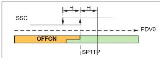
Light-on mode
SP1 = TP - H
12.1.1.3 SP1 Teach on background

Light-on mode
SP1 = TP + 2H
12.1.1.4 SP1 Teach on position

Light-on mode
SP1 = TP
12.1.1.5 SP1 Dynamic teach
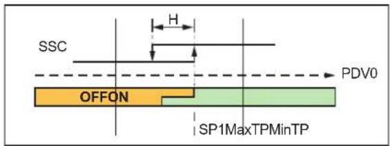
Light-on mode
SP1 = √(MinTP*MaxTP)
SP: Setpoint
H: Hysteresis
TP: Teach point
MinTP: Minimum teach point
MaxTP: Maximum teach point
SSC: SwitchingSignalChannel
12.1.2 Window mode
12.1.2.1 SP1 Two Values teach

Light-on mode
$$ \mathrm{SP1} = \sqrt {(\mathrm{TP1} ^ {*} \mathrm{TP2})} $$
SP: Setpoint
H: Hysteresis
TP: Teach point
MinTP: Minimum teach point
MaxTP: Maximum teach point
SSC: SwitchingSignalChannel
13 Maintenance, repair and disposal
Faulty sensors must only be repaired by the manufacturer.
▶ Keep the fibre-optic heads free from soiling.
▶ After use dispose of the device in an environmentally friendly way in accordance with the applicable national regulations.
▶ Do not open the module housing. There are no user-serviceable components inside.
14 Factory setting
| Parameter Setting range Factory setting Own setting | |||
| [Output function] Ou1: OFF; SSC1; SSC2 Ou1: SSC1 | |||
| Ou2: OFF; SSC1; SSC2 Ou2: OFF | |||
| [Mode] SINGLE POINT; WINDOW SINGLE POINT | |||
| [Output logic] HIGH ACTIVE; LOW ACTIVE HIGH ACTIVE | |||
| [Hysteresis] 1...20% 5% | |||
| [Delay mode] NO DELAY; ON; OFF; ON &OFF; IMPULSE; ON & IM-PULSE | NO DELAY | ||
| [Polarity] PNP; NPN PNP | |||
| [Transmitter LED] | ON; OFF; PDOUT | ON | |
| [Transmitter intensity] | 1...100 | 100% | |
| [Smart mode] | ON; OFF | ON | |
| [Operating mode] | HIGH SPEED; FAST;STANDARD; FINE; POWER;HIGH POWER | STANDARD | |
| [Auto SP adjustment] | ON; OFF | OFF | |
| [Language] | ENGLISH; GERMAN;FRENCH... | ENGLISH | |
| [Layout] | 4 DIGITS; BARGRAPH; EX-CESS GAIN | 4 DIGITS | |
| [Scheme] | ECO; OFF | ECO | |
| [Brightness] | 25%; 50%; 75%; 100% | 75% | |
| [Orientation] | 0^ ; 180^ | 0^ | |
- Contents
- Preliminary note
- Symbols used
- Safety instructions
- Intended use
- Function
- Measuring principle
- Operating modes
- Switching mode
- Operation with IO-Link master
- Installation
- Attaching the fibre optics
- Electrical connection
- PNP/NPN selection
- Operating and display elements
- LED states
- Set-up
- Guided teach / teaching process
- Selecting the [Language]
- Selecting the [Polarity]
- Selecting the [Teach method]
- 2-point teach
- Teaching an object
- Teaching the background
- Run mode
- Guided teach / extended teaching process
- Menu
- Basic functions
- Extended functions
- Operation
- Operating modes
- Parameter setting
- Parameter level basic functions
- [New teach OUT1]
- [OUT1 Setpoint1]
- 43951753
- [OUT1 Setpoint2]
- [Operating mode]
- [Fibre optics flashing]
- [Ext. functions]
- [Back]
- Parameter setting of extended functions
- [Configuration]
- [Output 1]
- [Output function]
- [Mode]
- Options:
- [Output logic]
- [Setpoint1]
- [Hysteresis]
- Set the hysteresis.
- [Delay mode]
- Set the delay mode.
- [Back]
- [Output 2]
- [Display]
- [Device info]
- [Factory setting]
- [Back]
- Submenu [Configuration] CFG
- [Polarity]
- [Transmitter LED]
- [Transmitter intensity]
- [Smart mode]
- [Operating mode]
- [Auto SP tracking]
- Auto SP tracking function
- [Fibre optics flashing]
- Restart guide
- [Back]
- Submenu [Display] DIS
- [Language]
- Select the menu language.
- [Layout]
- [Scheme]
- [Brightness]
- [Orientation]
- [Back]
- Setting
- Setting the range
- Single point mode
- SP1 Teach on background
- SP1 Teach on position
- SP1 Dynamic teach
- Window mode
- Maintenance, repair and disposal
Brand : IFM
Model : OCF501
Category : Optical sensor