
PT2334 - Sensor IFM - Free user manual and instructions
Find the device manual for free PT2334 IFM in PDF.


| Product Type | Electronic pressure sensor |
| Brand | IFM |
| Model | PT2334 |
| Category | Sensor |
| Application | Industrial applications, hydraulic systems |
| Pressure Type | Relative pressure |
| Output Signal | Analog 4...20 mA |
| Process Connection | 14-18 NPT |
| Maximum Tightening Torque | 50 Nm |
| Power Supply Voltage | To EN 50178, SELV, PELV (typical 10-30 V DC) |
| Vacuum Resistance | Yes |
| Overload Protection | Avoid exceeding maximum permissible pressure |
| Bursting Pressure | Must not be exceeded even for short time |
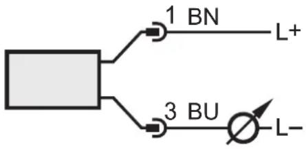
| Electrical Connection | BN (brown) = supply positive, BU (blue) = supply negative, OUT = analog output 4-20 mA |
| Safety Instructions | Read manual, use by qualified personnel, risk of injury if misused |
| Compliance | Pressure Equipment Directive (PED) for group 2 fluids |
| Environmental Protection | Use in protected environments, limit overvoltage pulses to max. 500 V |
| Additional Feature | Integrated diaphragm attachment (0.3 mm hole) for hydraulic damping |
| Maintenance | Keep clean; no specific maintenance required |
Frequently Asked Questions - PT2334 IFM
User questions about PT2334 IFM
0 question about this device. Answer the ones you know or ask your own.
Ask a new question about this device
Download the instructions for your Sensor in PDF format for free! Find your manual PT2334 - IFM and take your electronic device back in hand. On this page are published all the documents necessary for the use of your device. PT2334 by IFM.
USER MANUAL PT2334 IFM
Operating instructions Electronic pressure sensor for industrial applications
PT2334
UK
80297756 / 00 10 / 2020
natural_image
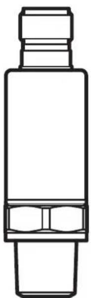
Line drawing of a cylindrical mechanical component with a flanged top and side connectors (no text or symbols)Contents
1 Preliminary note....2
1.1 Symbols used ....2
2 Safety instructions .... 2
3 Functions and features .... 3
3.1 Applications .... 3
3.2 Use in hydraulic systems ....4
4 Functions....4
5 Installation....5
6 Electrical connection....5
1 Preliminary note
1.1 Symbols used
▶ Instruction
Reaction, result
[...] Designation of keys, buttons or indications
→ Cross-reference

Important note
Non-compliance may result in malfunction or interference

Information
Supplementary note
2 Safety instructions
- The device described is a subcomponent for integration into a system.
- The manufacturer of the system is responsible for the safety of the system.
-
The system manufacturer undertakes to perform a risk assessment and to create a documentation in accordance with legal and normative requirements to be provided to the operator and user of the system. This documentation must contain all necessary information and safety instructions for the operator, the user and, if applicable, for any service personnel authorised by the manufacturer of the system.
-
Read this document before setting up the product and keep it during the entire service life.
- The product must be suitable for the corresponding applications and environmental conditions without any restrictions.
- Only use the product for its intended purpose (→ Functions and features).
- Only use the product for permissible media (→ Technical data).
- If the operating instructions or the technical data are not adhered to, personal injury and/or damage to property may occur.
- The manufacturer assumes no liability or warranty for any consequences caused by tampering with the product or incorrect use by the operator.
- Installation, electrical connection, set-up, operation and maintenance of the unit must be carried out by qualified personnel authorised by the machine operator.
- Protect units and cables against damage.
3 Functions and features
The pressure sensor detects the system pressure and converts it into an analogue output signal.
3.1 Applications
• Type of pressure: relative pressure

Information on pressure rating and bursting pressure → data sheet.

Pressure Equipment Directive (PED):
The units comply with the Pressure Equipment Directive and are designed and manufactured for group 2 fluids in accordance with the sound engineering practice. Use of group 1 fluids on request!

Avoid overload pressure exceeding the specified maximum permissible pressure by taking appropriate measures.
The indicated bursting pressure must not be exceeded.
Even if the bursting pressure is exceeded only for a short time, the unit may be destroyed. ATTENTION: Risk of injury!

If the cable length exceeds 30 m or if used outside buildings, there is a risk of overvoltage pulses from external sources. We recommend to use the unit in protected operating environments and to limit overvoltage pulses to max. 500 V.

The units are vacuum resistant.
3.2 Use in hydraulic systems
Restrictor in the process connection:
In hydraulic systems, highly dynamic effects such as pressure peaks, cavitation etc. may arise depending on the operating conditions. To reduce these effects on the measuring element of the sensor, a diaphragm attachment is integrated into the process connection. The specific thread pitch of the diaphragm attachment has the effect of a hole of 0.3 mm.

Please note: High viscosity may reduce the response time by some milliseconds. Heavy soiling may affect the functionality.
4 Functions
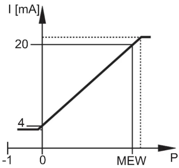
Current output 4...20 mA
line
| P | I [mA] | | ---- | ------ | | 0 | 4 | | MEW | 20 |P = system pressure, MEW = final value of the measuring range
In the measuring range the output signal is between 4 and 20 mA.
If the system pressure is above or below the measuring range, the analogue output behaves, without achieving the accuracy, as follows:
- System pressure above the measuring range: 20...25 mA.
- System pressure below the measuring range: 4...3 mA.
5 Installation

Before installing and removing the unit: make sure that no pressure is applied to the system.
▶ Insert the unit in a 14 -18 NPT process connection.
▶ Tighten firmly. Recommended tightening torque: max. 50 Nm.
Depends on lubrication, seal and pressure load!
6 Electrical connection

The unit must be connected by a qualified electrician.
The national and international regulations for the installation of electrical equipment must be adhered to.
Voltage supply to EN 50178, SELV, PELV.

For marine applications (if approval available for the device), additional surge protection is required.
▶ Disconnect power.
▶ Connect the unit as follows:
| Core colours | 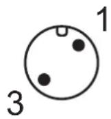 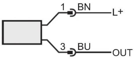 | ||
| BN brown | |||
| BU blue | |||
| OUT: analogue output 4...20 mAColours to DIN EN 60947-5-2 | |||
| Example circuit | |||
 | |||
More information at www.ifm.com
Brand : IFM
Model : PT2334
Category : Sensor