
IPB-16S - Temperature Controller Inkbird - Free user manual and instructions
Find the device manual for free IPB-16S Inkbird in PDF.


Pick your language and provide your email: we'll send you a specifically translated version.
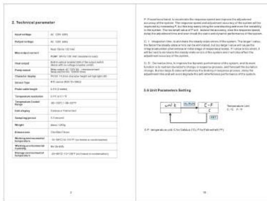
| Product Type | PID Temperature Controller |
| Model | IPB-16S |
| Brand | Inkbird |
| Input Voltage | AC 100-240V, 50/60Hz |
| Output Relay Rating | 16A @ 250VAC (resistive) |
| Temperature Measurement Range | -60°C to 400°C (-76°F to 752°F) |
| Temperature Control Range | -40°C to 300°C (-40°F to 572°F) |
| Sensor Type | NTC 10K (or PT100 optional) |
| Control Method | PID / ON-OFF (selectable) |
| Accuracy | ±0.5°C (±0.9°F) |
| Display | Dual LED display (PV/SV) |
| Dimensions (Panel Cutout) | 72 x 72 mm (2.83 x 2.83 in) |
| Overall Dimensions | 72 x 72 x 92 mm (2.83 x 2.83 x 3.62 in) |
| Weight | Approx. 1 kg (2.2 lb) |
| Sampling Period | 0.3 seconds |
| Ambient Temperature (Operating) | -10°C to 60°C (14°F to 140°F) |
| Humidity (Operating) | 35% to 85% RH (non-condensing) |
| Self-Tuning | Yes (AT function) |
| Alarm Output | Yes (high/low alarm) |
| Protection | Sensor break protection, over-range protection |
| Maintenance | Clean with dry cloth; avoid moisture and dust |
| Spare Parts | Replacement sensors, relays (contact manufacturer) |
Frequently Asked Questions - IPB-16S Inkbird
How do I connect the sensor to the Inkbird IPB-16S?
Connect the NTC 10K sensor to terminals 1 and 2 (or PT100 to 3 and 4). Ensure correct polarity for PT100. Refer to the wiring diagram in the manual.
What is the default PID setting and how can I adjust it?
Default PID values are P=53, I=53, D=8. To adjust, enter the parameter setting mode by pressing and holding 'SET' for 3 seconds. Navigate with arrow keys and adjust values using up/down buttons.
How do I perform a self-tuning (AT) on this controller?
Press and hold the 'SET' key until 'AT' appears on the display. Release, then press 'SET' again to start auto-tuning. The controller will heat and cool a few times to find optimal PID parameters. This process can take several minutes.
Can I switch between Celsius and Fahrenheit?
Yes. In the advanced settings menu (press 'SET' for 5 seconds), locate the parameter 'C/F' and change it to 'C' for Celsius or 'F' for Fahrenheit. Press 'SET' to confirm.
What should I do if the display shows 'Err' or 'E-1'?
An error code indicates a sensor or wiring issue. 'Err' means sensor break or short circuit. Check sensor connections and replace if damaged. 'E-1' may indicate over-range; verify the measured temperature is within controller limits.
How do I set a high or low temperature alarm?
Enter the parameter settings. Look for 'AH' (high alarm) and 'AL' (low alarm). Set the desired limit values. The alarm output relay will activate when the temperature exceeds or falls below these limits.
What is the maximum load current for the output relay?
The relay is rated for 16A at 250VAC for resistive loads. For inductive loads (e.g., motors), derate to 8A. Ensure the load does not exceed these ratings to avoid damage.
Is the controller suitable for cooling applications?
Yes. You can configure the output for cooling by setting the control mode to reverse action. In the parameter menu, change 'Ctrl' to 'REV' (reverse). The output relay will then energize to turn on cooling equipment when temperature rises.
How do I reset the controller to factory defaults?
Press and hold the 'SET' key for 10 seconds until '---' appears on the display. Release, and the controller will reset all parameters to factory defaults. Note: This erases any custom settings.
Can I use a different type of temperature sensor?
The IPB-16S is designed primarily for NTC 10K thermistors. However, it can support PT100 RTD sensors if the input type parameter (Sn) is changed to 'Pt100' in the advanced settings. Verify compatibility before use.
User questions about IPB-16S Inkbird
0 question about this device. Answer the ones you know or ask your own.
Ask a new question about this device
No questions yet. Be the first to ask one.
Download the instructions for your Temperature Controller in PDF format for free! Find your manual IPB-16S - Inkbird and take your electronic device back in hand. On this page are published all the documents necessary for the use of your device. IPB-16S by Inkbird.
USER MANUAL IPB-16S Inkbird
flowchart
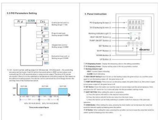
```mermaid
graph TD
    A["Control parameter set (c): B1@B2@C1=123"] --> B["Control period (s), B2@B3@D=123"]
    B --> C["Control period (s), B2@B3@D=123"]
    C --> D["Control period (s), B2@B4@C=123"]
    D --> E["Control period (s), B2@B5@D=123"]
    E --> F["Control period (s), B2@B6@D=123"]
    F --> G["Control period (s), B2@B7@D=123"]
    G --> H["Control period (s), B2@B8@D=123"]
    H --> I["Control period (s), B2@B9@D=123"]
    I --> J["Control period (s), B2@C0@D=123"]
    J --> K["Control period (s), B2@C1@D=123"]
    K --> L["Control period (s), B2@C2@D=123"]
    L --> M["Control period (s), B2@C3@D=123"]
    M --> N["Control period (s), B2@C4@D=123"]
    N --> O["Control period (s), B2@C5@D=123"]
    O --> P["Control period (s), B2@C6@D=123"]
    P --> Q["Control period (s), B2@C7@D=123"]
    Q --> R["Control period (s), B2@C8@D=123"]
    R --> S["Control period (s), B2@C9@D=123"]
    S --> T["Control period (s), B2@C10@D=123"]
    T --> U["Control period (s), B2@C11@D=123"]
    U --> V["Control period (s), B2@C12@D=123"]
    V --> W["Control period (s), B2@C13@D=123"]
    W --> X["Control period (s), B2@C14@D=123"]
    X --> Y["Control period (s), B2@C15@D=123"]
    Y --> Z["Control period (s), B2@C16@D=123"]
    Z --> AA["Control period (s), B2@C17@D=123"]
    AA --> AB["Control period (s), B2@C18@D=123"]
    AB --> AC["Control period (s), B2@C19@D=123"]
    AC --> AD["Control period (s), B2@C20@D=123"]
    AD --> AE["Control period (s), B2@C21@D=123"]
    AE --> AF["Control period (s), B2@C22@D=123"]
    AF --> AG["Control period (s), B2@C23@D=123"]
    AG --> AH["Control period (s), B2@C24@D=123"]
    AH --> AI["Control period (s), B2@C25@D=123"]
    AI --> AJ["Control period (s), B2@C26@D=123"]
    AJ --> AK["Control period (s), B2@C27@D=123"]
    AK --> AL["Control period (s), B2@C28@D=123"]
    AL --> AM["Control period (s), B2@C29@D=123"]
    AM --> AN["Control period (s), B2@C30@D=123"]
    AN --> AO["Control period (s), B2@C31@D=123"]
    AO --> AP["Control period (s), B2@C32@D=123"]
    AP --> AQ["Control period (s), B2@C33@D=123"]
    AQ --> AR["Control period (s), B2@C34@D=123"]
    AR --> AS["Control period (s), B2@C35@D=123"]
    AS --> AT["Control period (s), B2@C36@D=123"]
    AT --> AU["Control period (s), B2@C37@D=123"]
    AU --> AV["Control period (s), B2@C38@D=123"]
    AV --> AW["Control period (s), B2@C39@D=123"]
    AW --> AX["Control period (s), B2@C40@D=123"]
    AX --> AY["Control period (s), B2@C41@D=123"]
    AY --> AZ["Control period (s), B2@C42@D=123"]
    AZ --> BA["Control period (s), B2@C43@D=123"]
    BA --> BB["Control period (s), B2@C44@D=123"]
    BB --> BC["Control period (s), B2@C45@D=123"]
    BC --> BD["Control period (s), B2@C46@D=123"]
    BD --> BE["Control period (s), B2@C47@D=123"]
    BE --> BF["Control period (s), B2@C48@D=123"]
    BF --> BG["Control period (s), B2@C49@D=123"]
    BG --> BH["Control period (s), B2@C50@D=123"]
    BH --> BI["Control period (s), B2@C51#D=123"]
    BI --> BJ["Control period (s), B2#B5#D=123"]
    BJ --> BK["Control period (s), B2#B6#D=123"]
    BK --> BL["Control period (s), B2#B7#D=123"]
    BL --> BM["Control period (s), B2#B8#D=123"]
    BM --> BN["Control period (s), B2#B9#D=123"]
    BN --> BO["Control period (s), B2#B10#D=123"]
    BO --> BP["Control period (s), B2#B11#D=123"]
    BP --> BQ["Control period (s), B2#B12#D=123"]
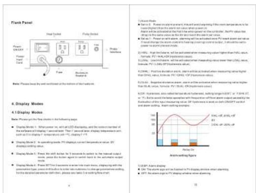
    BQ --> BR[Panel Instruction
PV Displaying Button: Displaying measuring value on the setting parameters
PV Reploding Button: Displaying value on the set of product required
PV Inducturing Indicator: Displaying value on the set of product required
PV Inducturing Index: Displaying value on the set of product required
PV Inducturing Current: Displaying value on the set of product required
PV Inducturing Current: Displaying value on the set of product required
PV Inducturing Current: Displaying value on the set of product required
PV Inducturing Current: Displaying value on the set of product required
PV Inducturing Current: Displaying value on the set of product required
PV Inducturing Current: Displaying value on the set of product required
PV Inducturing Current: Displaying Value on the set of product required
PV Inducturing Current: Displaying Value on the set of product required
PV Inducturing Current: Displaying Value on the set of product required
PV Inducturing Current: Displaying Value on the set of product required
PV Inducturing Current: Displaying Value on the set of product required
PV Inducturing Current: Displaying Value on the set of product required
PV Inducturing Current: Displaying Value on the set off from the system
PV Inducturing Current: Displaying Value on the set off from the system required
PV Inducturing Current: Displaying Value on the set off from the system required
PV Inducturing Current: Displaying Value on the set off from the system required
PV Inducturing Current: Displaying Value on the set off from the system required
PV Inducturing Current: Displaying Value on the set off from the system required
PV Inducturing Current: Displaying Value on the set off from the system required
PV Inducturing Current: Displaying Time to the system required
PV Inducturing Current: Displaying Time to the system required
PV Inducturing Current: Displaying Time to the system required
PV Inducturing Current: Displaying Time to the system required
PV Inducturing Current: Displaying Time to the system required
PV Inducturing Current: Displaying Time to the system required
PV Inducturing Current: Displaying Time to the system required
PV Inducturing Current: Displaying Time to the System required
PV Inducturing Current: Displaying Time to the System required
PV Inducturing Current: Displaying Time to the System required
PV Inducturing Current: Displaying Time to the System required
PV Inducturing Current: Displaying Time to the System required
PV Inducturing Current: Displaying Time to the System required
PV Inducturing Current: Displaying Time to the System required
PV Inducturing Current: Displaying Time to the System required

Panel Instruction
PV Displaying Button: Displaying measuring value on the setting parameters
PV Repluding Button: Displaying testing value on the set of product required
PV Inducturing Indicator: Displaying value on the set of product required
PV Inducturing Current: Displaying value on the set of product required
PV Inducturing Current: Displaying value on the set of product required
PV Inducturing Current: Displaying value on the set of product required
PV Inducturing Current: Displaying value on the set of product required
PV Inducturing Current: Displaying value on the set of product required
PV Inducturing Current: Displaying time to the system required
PV Inducturing Current: Displaying time to the system required
PV Inducturing Current: Displaying time to the system required
PV Inducturing Current: Displaying time to the system required
PV Inducturing Current: Displaying time to the system required
PV Inducturing Current: Displaying time to the system required
PV Inducturing Current: Displaying time to the system required
PV Inducturing Current: Displaying time to the system required

Panel Instruction
PV Displaying Button: Displaying measuring value on the setting parameters
PV Repluding Button: Displaying testing value on the set of product required
PV Inducturing Indicator: Displaying value on the set of product required
PV Inducturing Current: Displaying value on the set of product required
PV Inducturing Current: Displaying value on the set of product required
PV Inducturing Current: Displaying time to the system required
PV Inducturing Current: Displaying time to the system required
PV Inducturing Current: Displaying time to the system required
PV Inducturing Current: Displaying time to the system required
PW Inducturing Button: Displaying time to the system required
PW Inducturing Current: Displaying time to the system required
PW Inducturing Current: Displaying time to the system required
PW Inducturing Current: Displaying time to the system required
PW Inducturing Current: Displaying time to the system required
PW Inducturing Current: Displaying time to the system required
PW Inducturing Current: Displaying time to the system required
PW Inducturing Current: Displaying time to the system required
PW Inducturing Current:Displaying Time to the system required
PW Inducturing Current:Displaying Time to the system required
PW Inducturing Current:Displaying Time to the system required
PW Inducturing Current:Displaying Time to the system required
PW Inducturing Current:Displaying Time to the system required
PW Inducturing Current:Displaying Time to the system required
PW Inducturing Current:Displaying Time to the system required
PW Inducturing Current:Displaying Time tothe system required
PW Inducturing Current:Displaying Time to the system required
PW Inducturing Current:Displaying Time to the system required
PW Inducturing Current:Displaying Time to the system required
PW Inducturing Current:Displaying Time to the system required
PW Inducturing Current:Displaying Time to the system required
PW Inducturing Current:Displaying Time to the system required
PW Inducturing Current:Displaying Time to the system require<nl>
flowchart
graph TD
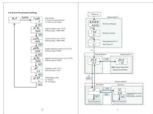
    A["RL_P"] --> B["H1_RL"]
    B --> C["La_RL"]
    C --> D["gh_RL"]
    D --> E["dF"]
    E --> F["dL_P"]
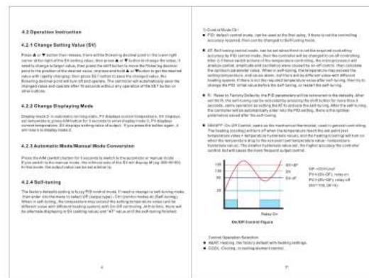
    F --> G["Display Mode 1"]
    G --> H["Full-Alarm Display"]
    H --> I["Software Version"]
    I --> J["Performance Unit: C Input Type PI"]
    J --> K["Display Model 2"]
    K --> L["Display Model 3"]
    L --> M["Display Model 4"]
    M --> N["Data Pricing & Optimization"]
    N --> O["Data Pricing & Optimization"]
    O --> P["Data Pricing & Optimization"]
    P --> Q["Data Pricing & Optimization"]
    Q --> R["Data Pricing & Optimization"]
    R --> S["Data Pricing & Optimization"]
    S --> T["Data Pricing & Optimization"]
    T --> U["Data Pricing & Optimization"]
    U --> V["Data Pricing & Optimization"]
    V --> W["Data Pricing & Optimization"]
    W --> X["Data Pricing & Optimization"]
    X --> Y["Data Pricing & Optimization"]
    Y --> Z["Data Pricing & Optimization"]
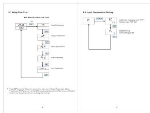
flowchart
graph TD
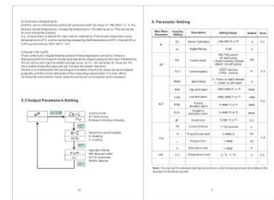
    A["25.0 10.0"] --> B["IP"]
    B --> C["QP"]
    C --> D["RL P"]
    D --> E["PI df"]
    E --> F["QDT"]
    F --> G["JWt2 k"]
    G --> H["QDT"]
    H --> I["Input Parameters"]
    I --> J["Output Parameters"]
    J --> K["Input Parameters"]
    K --> L["QPT"]
    L --> M["RL P"]
    M --> N["PI df"]
    N --> O["QDT"]
    O --> P["JWt2 k"]
Manual assistant
Powered by Anthropic
Waiting for your message
Product information
Brand : Inkbird
Model : IPB-16S
Category : Temperature Controller