
DKM-500BWJ - Sorbet maker Hoshizaki - Free user manual and instructions
Find the device manual for free DKM-500BWJ Hoshizaki in PDF.


| Product Type | Crescent Cube Icemaker and Dispenser (Water-Cooled) |
| Model Number | DKM-500BWJ |
| Ice Production per Cycle | 7.2 lbs (3.3 kg) / 360 cubes |
| Approximate Storage Capacity | 140 lbs (64 kg) |
| Ice Dispense Rate | 13 lb/min (6 kg/min) |
| Electrical Supply | 115 V, 60 Hz, 1-Phase |
| Amperage (at 5 min freeze, 104°F ambient) | 12 A |
| Minimum Circuit Ampacity | 20 A |
| Maximum Fuse Size | 20 A |
| Refrigerant Type and Charge | R404A, 1 lb 2 oz (510 g) |
| Bin Control System | Proximity switch with delay (mechanical bin control) |
| Ambient Temperature Range | 45°F to 100°F (7°C to 38°C) |
| Water Supply Connection | Required (cold water line, 1/4" male flare fitting recommended) |
| Cleaning and Maintenance | Daily scoop cleaning, bi-weekly air filter, monthly water filter, yearly full cleaning and sanitizing |
| Adjustable Settings | Harvest timer, freeze timer, pump-out timer and frequency via dip switches |
| Safety Features | High-pressure switch, control board alarms (temperature, harvest backup, freeze timer, voltage), automatic shutdown |
| Warranty | Refer to manual; improper installation voids warranty |
| Required Service | Only qualified service technicians should install and service |
| Condenser Type | Water-cooled (water regulating valve included) |
| Approximate Dimensions (H x W x D) | Not specified in manual, typical for this series: approx. 30" x 22" x 28" |
Frequently Asked Questions - DKM-500BWJ Hoshizaki
User questions about DKM-500BWJ Hoshizaki
0 question about this device. Answer the ones you know or ask your own.
Ask a new question about this device
Download the instructions for your Sorbet maker in PDF format for free! Find your manual DKM-500BWJ - Hoshizaki and take your electronic device back in hand. On this page are published all the documents necessary for the use of your device. DKM-500BWJ by Hoshizaki.
USER MANUAL DKM-500BWJ Hoshizaki
Crescent Cube Icemaker / Dispenser
Models
DKM-500BAJ
DKM-500BWJ
WARNING
Only qualified service technicians should install and service the appliance. To obtain the name and phone number of your local Hoshizaki Certified Service Representative, visit www.hoshizaki.com. No service should be undertaken until the technician has thoroughly read this Service Manual. Failure to service and maintain the appliance in accordance with this manual will adversely affect safety, performance, component life, and warranty coverage. Proper installation is the responsibility of the installer. Product failure or property damage due to improper installation is not covered under warranty.
Hoshizaki provides this manual primarily to assist qualified service technicians in the service of the appliance.
Should the reader have any questions or concerns which have not been satisfactorily addressed, please call, send an e-mail message, or write to the Hoshizaki Technical Support Department for assistance.
Phone: 1-800-233-1940; (770) 487-2331
Fax: 1-800-843-1056; (770) 487-3360
E-mail: techsupport@hoshizaki.com
618 Highway 74 South
Peachtree City, GA 30269
Attn: Hoshizaki Technical Support Department
Web Site: www.hoshizaki.com
NOTE: To expedite assistance, all correspondence/communication MUST include the following information:
- Model Number ____
- Serial Number
- Complete and detailed explanation of the problem.
IMPORTANT
This manual should be read carefully before the appliance is serviced. Read the warnings and guidelines contained in this manual carefully as they provide essential information for the continued safe use, service, and maintenance of the appliance. Retain this manual for any further reference that may be necessary.
CONTENTS
Important Safety Information....5
I. Construction and Water/Refrigeration Circuit Diagram 7
A. Construction....7
-
Air-Cooled Models (BAJ) 7
-
Water-Cooled Models (BWJ) 8
B. Water/Refrigeration Circuit Diagram....9
-
Air-Cooled Models (BAJ) 9
-
Water-Cooled Models (BWJ) 10
II. Sequence of Operation and Service Diagnosis....11
A. Sequence of Operation Flow Chart....11
B. Service Diagnosis 12
C. Control Board Check.... 19
D. Bin Control Check 20
E. Switches....22
-
Control Switch 22
-
Service Switch.... 22
F. Float Switch Check and Cleaning 23
-
Float Switch Check 23
-
Float Switch Cleaning....24
G. Thermistor Check....25
H. Diagnostic Tables 26
III. Controls and Adjustments 30
A. Control Board Layout 31
B. LED Lights and Audible Alarm Safeties.... 32
C. Settings and Adjustments....33
-
Default Dip Switch Settings 33
-
Harvest Timer (S4 dip switch 1 & 2) 33
-
Pump-Out Timer (S4 dip switch 3 & 4) 34
-
Pump-Out Frequency Control (S4 dip switch 5)....34
-
Harvest Pump Time (S4 dip switch 6)....35
-
Harvest Pump Timer Operation (S4 dip switch 7)....35
-
Factory Use (S4 dip switch 8).... 36
-
Freeze Timer (S4 dip switch 9 & 10)....36
-
Float Switch Selector (S5 dip switch 1) 36
-
Refill Counter (S5 dip switch 2 and 3)....36
-
Minimum Harvest Time (S5 dip switch 4) 37
-
Anti-Slush (S5 dip switch 5)....37
IV. Refrigeration Circuit and Component Service Information.... 38
A. Refrigeration Circuit Service Information 38
B. Component Service Information.... 41
C. Water Regulating Valve Adjustment (water-cooled model) 41
V. Maintenance 42
VI. Preparing the Appliance for Periods of Non-Use 43
VII. Disposal....45
VIII. Technical Information....46
A. Specification and Performance Data Sheets.... 46
- DKM-500BAJ 46
- DKM-500BWJ 47
B. Wiring Diagram 48
Important Safety Information
Throughout this manual, notices appear to bring your attention to situations which could result in death, serious injury, damage to the appliance, or damage to property.
⚠ WARNING Indicates a hazardous situation which could result in death or serious injury.
NOTICE Indicates a situation which could result in damage to the appliance or property.
IMPORTANT Indicates important information about the use and care of the appliance.
WARNING
The appliance should be destined only to the use for which it has been expressly conceived. Any other use should be considered improper and therefore dangerous. The manufacturer cannot be held responsible for injury or damage resulting from improper, incorrect, and unreasonable use. Failure to service and maintain the appliance in accordance with this manual will adversely affect safety, performance, component life, and warranty coverage and may result in costly water damage.
To reduce the risk of death, electric shock, serious injury, or fire, follow basic precautions including the following:
- Only qualified service technicians should install and service this appliance.
- The appliance must be installed in accordance with applicable national, state, and local codes and regulations.
- The appliance requires an independent power supply of proper capacity. See the nameplate for electrical specifications. Failure to use an independent power supply of proper capacity can result in a tripped breaker, blown fuse, damage to existing wiring, or component failure. This could lead to heat generation or fire.
- THE APPLIANCE MUST BE GROUNDED: The appliance is equipped with a NEMA 5-20 three-prong grounding plug to reduce the risk of potential shock hazards. It must be plugged into a properly grounded, independent 3-prong wall outlet. If the outlet is a 2-prong outlet, it is your personal responsibility to have a qualified electrician replace it with a properly grounded, independent 3-prong wall outlet. Do not remove the ground prong from the power cord and do not use an adapter plug. Failure to properly ground the appliance could result in death or serious injury.
- Do not use an extension cord.
- To reduce the risk of electric shock, do not touch the control switch, service switch, or plug with damp hands. Make sure the control switch is in the "OFF" position before plugging in or unplugging the appliance.
- Do not use an appliance with a damaged power cord. The power cord should not be altered, jerked, bundled, weighed down, pinched, or tangled. Such actions could result in electric shock or fire. To unplug the appliance, be sure to pull the plug, not the cord, and do not jerk the cord.
⚠ WARNING, continued
- Do not make any alterations to the appliance. Alterations could result in electric shock, injury, fire, or damage to the appliance.
- The appliance is not intended for use by persons (including children) with reduced physical, sensory, or mental capabilities, or lack of experience and knowledge, unless they have been given supervision or instruction concerning use of the appliance by a person responsible for their safety.
- Children should be properly supervised around the appliance.
- Do not climb, stand, or hang on the appliance or allow children or animals to do so. Serious injury could occur or the appliance could be damaged.
- Do not use combustible spray or place volatile or flammable substances near the appliance. They might catch fire.
- Keep the area around the appliance clean. Dirt, dust, or insects in the appliance could cause harm to individuals or damage to the appliance.
NOTICE
- Follow the water supply, drain connection, and maintenance instructions carefully to reduce the risk of costly water damage.
- In areas where water damage is a concern, install in a contained area with a floor drain.
- Install the appliance in a location that stays above freezing. Normal operating ambient temperature must be within 45^ to 100^ (7°C to 38°C). If the normal operating ambient temperature is above 90^ (32°C), the compressor insulation cover must be removed.
- Do not leave the appliance on during extended periods of non-use, extended absences, or in sub-freezing temperatures. To properly prepare the appliance for these occasions, follow the instructions in "IV. Preparing the Appliance for Periods of Non-Use."
- Do not place objects on top of the appliance.
- The storage bin is for ice use only. Do not store anything else in the storage bin.
I. Construction and Water/Refrigeration Circuit Diagram
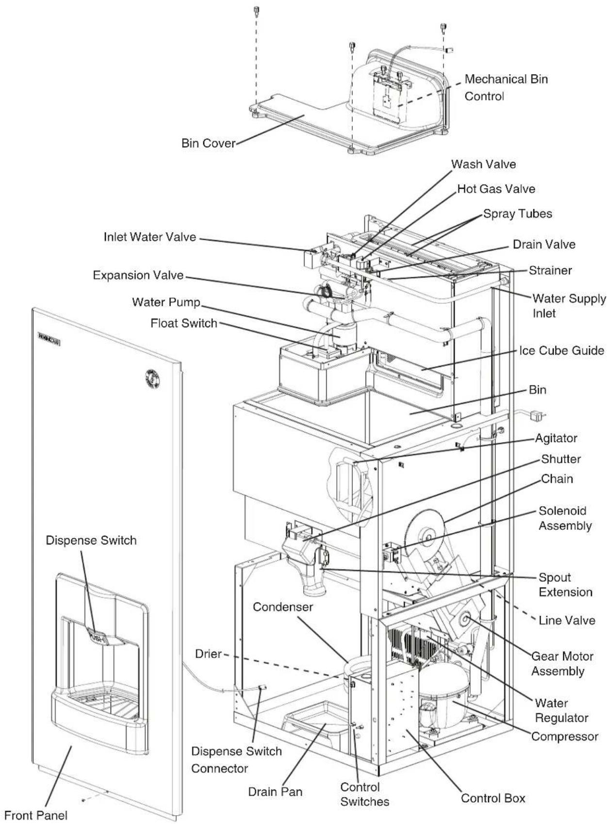
A. Construction
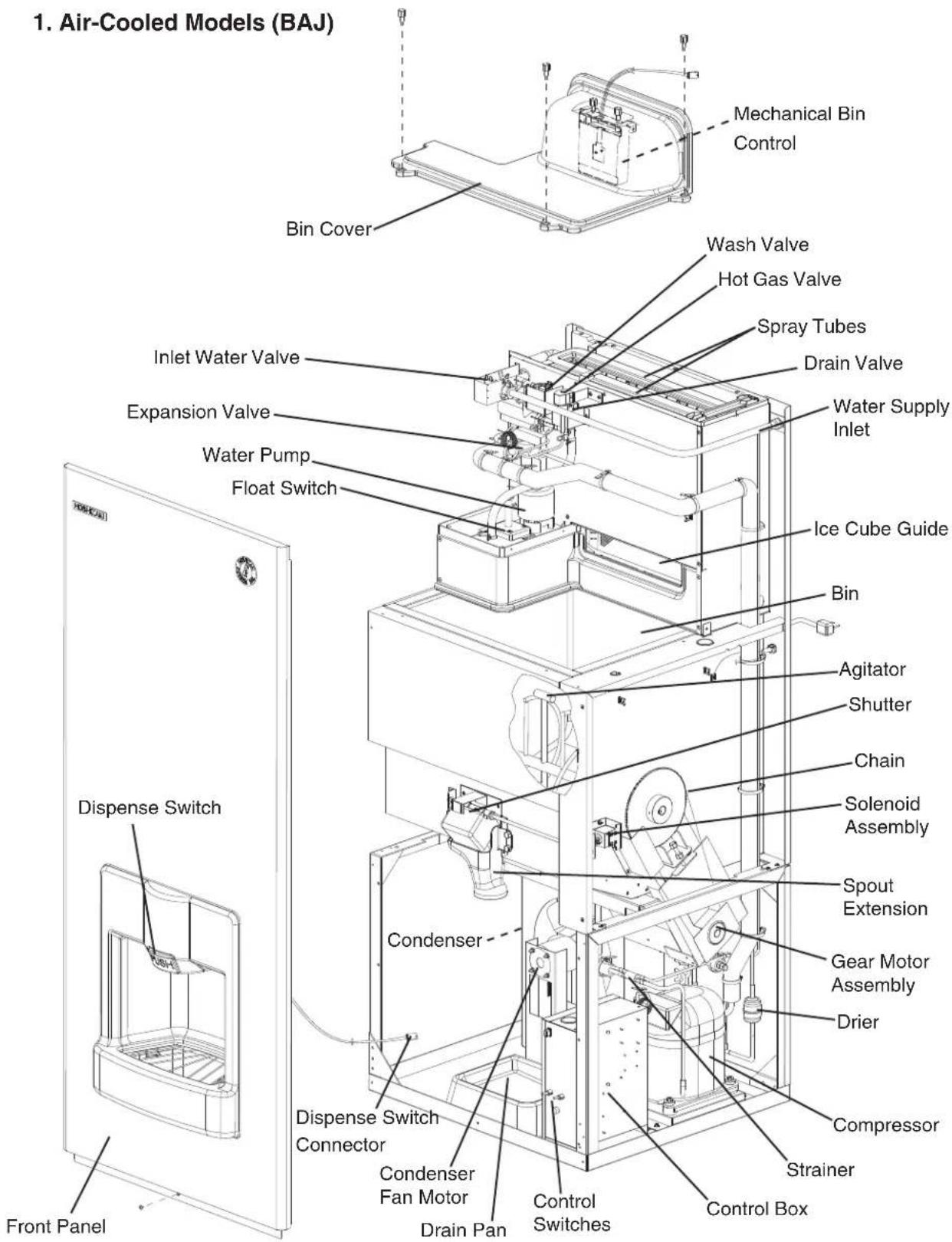
- Water-Cooled Models (BWJ)
B. Water/Refrigeration Circuit Diagram
1. Air-Cooled Models (BAJ)
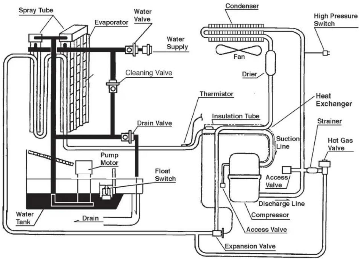
[EMPTY]
Refrigerant Circuit
-
Water Circuit
- Water-Cooled Models (BWJ)
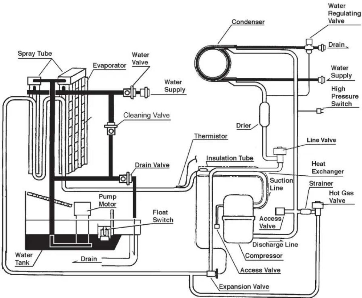
= Refrigerant Circuit
Water Circuit
II. Sequence of Operation and Service Diagnosis
A. Sequence of Operation Flow Chart
"J" Control Board With Harvest Pump Timer Operation Sequence Flow Chart
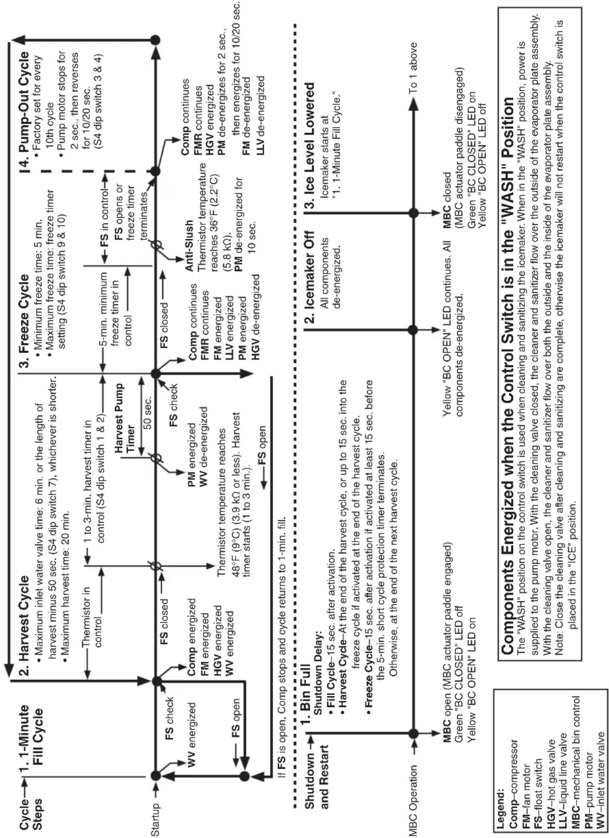
flowchart
graph TD
    A["Startup"] --> B["1. 1-Minute Fill Cycle"]
    B --> C["2. Harvest Cycle"]
    C --> D["3. Freeze Cycle"]
    D --> E["4. Pump-Out Cycle"]

    subgraph Start Step
        B -->|FS check WV energized| B
        B -->|FS open| B
        B -->|FS closed| B
        B -->|FS open| B
    end

    subgraph Closed Step
        C -->|Comp energized FM energized HGV energized WV energized| C
        C -->|FS closed| C
        C -->|FS open| C
        C -->|FS closed| C
        C -->|FM energized WV de-energized| C
        C -->|FM energized FM energized LLV energized PM energized HGV de-energized| C
        C -->|FM energized PP de-energized| C
        C -->|FM energized PP de-energized| C
        C -->|Anti-Slush Thermistor temperature reaches 36°F (2.2°C) (5.8 kΩ). PM de-energized for 10 sec.| D
        D -->|FS in control FS opens or freeze timer terminates| D
        D -->|FS closed| D
        D -->|Comp continues FMR continues FM energized LLV energized PM energized HGV de-energized| D
        D -->|Anti-Slush Thermistor temperature reaches 36°F (2.2°C) (5.8 kΩ). PM de-energized for 10 sec.| E
        E -->|Comp continues FMR continues HGV energized PM de-energizes for 2 sec., then energizes for 10/20 sec. FM de-energized LLV de-energized| E
    end

    subgraph Closed End
        F["Shutdown and Restart"]
        G["MBC Operation"] --> H["1. Bin Full Shutdown Delay: Fill Cycle–15 sec. after activation. Harvest Cycle–At the end of the harvest cycle, or up to 15 sec. into the freeze cycle if activated at the end of the harvest cycle. Freeze Cycle–15 sec. after activation if activated at least 15 sec. before the 5-min. short cycle protection timer terminates. Otherwise, at the end of the next harvest cycle."]
        I["To 1 above"] --> J["2. Icemaker Off All components de-energized."]
        J --> K["3. Ice Level Lowered Icemaker starts at "1. 1-Minute Fill Cycle.""]
        L["To 1 above"] --> M["MBC closed (MBC actuator paddle disengaged) Green "BC CLOSED" LED on Yellow "BC OPEN" LED off"]
    end

    N["Legend: Comp-compressor FM-fan motor FS-float switch HGV-hot gas valve LLV-liquid line valve MBC-mechanical bin control PM-pump motor WV-inlet water valve"] --> O["Components Energized when the Control Switch is in the "WASH" Position"]
    style A fill:#f9f,stroke:#333
    style B fill:#ccf,stroke:#333
    style C fill:#cfc,stroke:#333
    style D fill:#fcc,stroke:#333
    style E fill:#cff,stroke:#333
    style F fill:#ffc,stroke:#333
    style G fill:#cfc,stroke:#333
    style H fill:#fcc,stroke:#333
    style I fill:#cfc,stroke:#333
    style J fill:#cfc,stroke:#333
    style K fill:#cfc,stroke:#333
    style L fill:#cfc,stroke:#333
B. Service Diagnosis
WARNING
- The appliance should be diagnosed and repaired only by qualified service personnel to reduce the risk of death, electric shock, serious injury, or fire.
- Risk of electric shock. Control switch in "OFF" position does not de-energize all loads Use extreme caution and exercise safe electrical practices.
- Moving parts (e.g., fan blade) can crush and cut. Keep hands clear.
- Before servicing the appliance, move the control switch to the "OFF" position and turn off the power supply.
- CHOKING HAZARD: Ensure all components, fasteners, and thumbscrews are securely in place after the appliance is serviced. Make sure that none have fallen into the dispenser unit/ice storage bin.
- Make sure all food zones in the appliance and dispenser unit/ice storage bin are clean after service.
The diagnostic procedure is a sequence check that allows you to diagnose the electrical system and components. Before proceeding, check for correct installation, proper voltage per nameplate, and adequate water supply. Check CB using the steps in "II.C. Control Board Check." Check dip switch settings to assure that S4 dip switch 3, 4, 7, 8, 9, 10 and S5 dip switch 1 through 5 are in the factory default position. S4 dip switch 1, 2, 5, 6 are cleaning adjustments and the settings are flexible. For factory default settings, see "III.C.1. Default Dip Switch Settings."
Note: • When checking high voltage (115VAC), always choose a white (W) neutral wire to establish a good neutral connection.
- When checking voltage from the CB K1 connector (10 pin connector), pull CB K1 connector out slightly to allow room for multimeter test leads contact.
Confirm that the location meets installation requirements:
- The appliance is not intended for outdoor use. Normal operating ambient temperature should be within 45^ to 100^ (7°C to 38°C).
- Allow 6" (15 cm) clearance at rear, sides, and top for proper air circulation and ease of maintenance and/or service should they be required.
- The appliance should not be located in a corrosive environment.
1) Turn off the power supply, then access the control box. Move the control switch to the "OFF" position. Clear any ice from BC.
2) Check that the 115VAC 10A fuse is good.
1. Diagnosis
3) Power On: Turn on the power supply, then move the control switch to the "ICE" position. A 5-sec. delay occurs. CB red "POWER OK" LED and green "BC CLOSED" LED turn on. If yellow "BC OPEN" LED is on (indicating a full bin), check MBC. Move ice away from MBC actuator paddle. If yellow "BC OPEN" LED stays on, see "II.D. Mechanical Bin Control Check."
Note: • CB red "POWER OK" LED remains on unless the 10.5VAC power supply is interrupted (K2 connector).
- Check CB using the steps in "II.C. Control Board Check."
- Confirm CB green "BC CLOSED" LED is on. If CB yellow "BC OPEN" LED is on, remove ice from BC. If no ice is around BC and yellow "BC OPEN" LED is on, see "II.D. Mechanical Bin Control Check."
a) Power On Diagnosis: If CB red "POWER OK" LED is off, confirm 10A fuse is good. Check for 115VAC at control switch #2 (BK) to neutral (W) then at control switch #3 (P) to neutral (W). If 115VAC is present on #2 (BK) and not on #3 (P), replace control switch. If 115VAC is present on control switch #3 (P), check for 115VAC at HPS pink (P) wire to neutral (W) then HPS black (BK) wire to neutral (W). If 115VAC is present at HPS pink (P) wire and not at HPS black (BK) wire, HPS is open. See HPS Diagnosis below. If 115VAC is present at HPS black (BK) wire, check for 10.5VAC at CB K2 #1 red (R) wire to CB K2 #2 red (R) wire. If 10.5VAC is not present, check CT continuity. If open, replace CT.
b) HPS Diagnosis: Let refrigeration circuit pressures equalize. If HPS does not reset and pressures are equalized, replace HPS. Check that the condenser coil is not clogged or restricted and the FM is operating correctly. If pressures are not equalized, reclaim refrigerant and diagnose refrigeration circuit restriction. Check that there are no restrictions in the refrigeration circuit.
Harvest Cycle: HGV, strainer, or check valve.
Freeze Cycle: FM, TXV, WRV, HM, LLV, strainer, check valve, drier, and damaged line set or fitting.
4) 1-Min. Fill Cycle – LED 4 is on. WV and X11 relay energize. Water begins to fill the water tank. After 1 min., CB checks for a closed FS. If FS is closed, the harvest cycle begins (X10, X12, Comp, and HGV energize). Continue to step 5a. If FS is open, WV remains energized through additional 1-min. fill cycles until water enters the water tank and FS closes (low water safety protection during initial start up and at the end of each harvest).
Diagnosis: Check that water enters the water tank. If not, check that the water supply line shut-off valve is open and screens or external filters are clear. Check for 115VAC at CB K1 #6 (O) to neutral (W). If 115VAC is not present, replace CB. If 115VAC is present, and WV does not energize, check for 115VAC at WV. If 115VAC is present, check coil continuity. If open, replace WV. If the water tank fills, but the appliance fails to start harvest (Comp energized), check for open FS. See "II.E. Float Switch Check and Cleaning." If FS is closed and CB fails to start the harvest cycle after 1 min., replace CB.
5a) Initial Harvest Cycle – LEDs 1, 4, and 2 are on. WV and X11 relay continue. Comp, HGV, X12, and X10 relays energize. CB monitors the warming of the evaporator via the thermistor located on the suction line. When the thermistor reaches 48^ F ( 9^ C), CB reads 3.9 kΩ from the thermistor and turns harvest termination over to the harvest timer (S4 dip switch 1 & 2). The harvest timer has settings of 60, 90, 120, and 180 sec. The pump-out timer (S4 dip switch 3 & 4) acts in place of the harvest timer during cycles with a pump-out (S4 dip switch 5). WV and X11 relay are energized during harvest for a maximum of 6 min. or the length of harvest minus 50 sec., whichever is shorter. 50 sec. before harvest terminates, PM energizes. See step 5b below.
a) Comp Diagnosis: Check that evaporator is warming. If not, confirm that Comp energizes. If not, check for 115VAC at CB K1 #1 or #9 (V) to neutral (W). If 115VAC is not present, check for 115VAC at CB K1 #7 or #10 (BK) to neutral (W). If 115VAC is present at #7 or #10 (BK) and not at #1 or #9 (V), replace CB. If 115VAC is present, check for 115VAC at CR solenoid. If 115VAC is present, confirm contacts are closed. If not, replace CR. If CR contacts are closed, check Comp start and run capacitors, Comp start relay, and Comp motor winding.
b) HGV Diagnosis: If Comp is energized and evaporator is not warming, check that HGV energizes and opens. Check for 115VAC at CB K1 #2 (P) to neutral (W). If 115VAC is not present, replace CB. If 115VAC is present, check for 115VAC at HGV coil and check HGV coil continuity. Replace as needed.
c) LLV Diagnosis: Confirm that LLV is de-energized and closed (not bypassing). If energized, replace CB. If de-energized and bypassing, replace LLV.
d) WRV Diagnosis: Confirm WRV is not leaking by.
5b) Harvest Pump Time – LEDs 1, 3, and 2 are on. When the thermistor reaches 48^ F ( 9^ C), CB reads 3.9 kΩ from the thermistor and turns harvest termination over to the harvest timer (S4 dip switch 1 & 2). 50 sec. before the harvest timer terminates, LED 3 turns on and PM energizes. Comp, HGV, X10, and X12 relays continue. LED 4 turns off, WV and X11 relay de-energize.
a) Thermistor Diagnosis: Place a thermometer on the suction line next to the thermistor. Has it warmed to 48^ F ( 9^ C) or warmer? Confirm thermistor status. See "II.F. Thermistor Check."
b) Contorl Board Diagnosis: If the thermistor reading is in proper range, dip switch 7 is on and WV continues, check for 115VAC at CB K1 #6 (O) to neutral (W). If 115VAC is present, and LED 4 is off, replace CB. If LED 3 is on and PM is not energized, check for 115VAC at CB K1 #5 (DBU) to neutral (W). If 115VAC is not present, replace CB.
c) Relay Diagnosis: If 115VAC is present and PM is not energized, check for 115VAC at X12 relay terminal #8 (P) to terminal #7 neutral (W). If 115VAC is present, check for 115VAC at X12 relay terminal #6 (DBU) to neutral (W) and terminal #4 (Y) to neutral (W). If 115VAC is present on terminal #6 (DBU) and not on terminal #4 (Y), replace X12 relay.
d) Pump Motor Diagnosis: If 115VAC is present on X12 terminal #4 (Y) to neutral (W) and PM is not energized, check PM capacitor and motor winding continuity.
5c) Initial Harvest Cycle Termination Diagnosis: When the harvest timer (S4 dip switch 1 & 2) terminates, harvest cycle terminates. If 1-min. fill cycle starts after harvest timer terminates, check that FS is clean and operating properly, see "II.E. Float Switch Check and Cleaning." If FS is closed, CB proceeds to the next cycle. If not, replace CB.
Note: The minimum total time allowed by CB for a complete harvest cycle is 2 min.
Maximum harvest time allowed is 20 min.
IMPORTANT! S4 dip switch 7 must remain on. Otherwise, PM will not energize during the last 50 sec. of harvest.
6) Freeze Cycle – LED 1 is on. Comp and PM continue. FM and LLV (if applicable) energize. HGV, X10, and X12 relays de-energize. Appliance is held in freeze by a 5-min. short cycle protection timer. After 5-min. timer terminates and FS opens, freeze cycle terminates. When the thermistor reaches 36^ F ( 2.2^ C), CB reads 5.8 kΩ from the thermistor and de-energizes the PM for 10 sec. (anti-slush). After 10 sec. CB energizes PM and freeze cycle continues.
Note: PM power supply switches from CB K1 #5 (DBU) in harvest to K1 #4 (R) in freeze.
a) Freeze Cycle Diagnosis: Confirm Comp and PM continue. Confirm that FM and LLV (if applicable) energize. Confirm WRV (if applicable) opens. Next, confirm HGV, X10, and X12 relays de-energize. During the first 5 min. of freeze, confirm evaporator is cooling. If not, confirm WV de-energized (not leaking by), HGV de-energized (not bypassing), LLV (if applicable) and FM energize, TXV operating correctly, WRV (if applicable) opens, Comp is efficient, and refrigerant charge is correct. See "VIII.A. Specification and Performance Data Sheet."
When the thermistor reaches 36^ F ( 2.2^ C), CB reads 5.8 kΩ from the thermistor and de-energizes the PM for 10 sec. then, energizes PM for the duration of the freeze cycle.
b) Comp Diagnosis: If Comp de-energizes once freeze begins, check that appliance has not shut off on HPS ("POWER OK" LED off). If so, check "3)b) HPS Diagnosis." If "POWER OK" LED is on, check for 115VAC at CB K1 #1 (V) or #9 (V) to neutral (W). If 115VAC is not present and LED 1 is on, replace CB. If 115VAC is present, check for 115VAC at CR coil. If 115VAC is present, check CR coil and contact continuity. Replace as needed. If CR is okay, check Comp start relay and start and run capacitors. Next, check Comp motor winding continuity. If Comp is energized but evaporator is not cooling, check for an inefficient Comp. See "VIII.B. Performance Data Sheets."
c) WV and HGV Diagnosis: If WV is energized, check for 115VAC at CB K1 #6 (O) to neutral (W). If 115VAC is present after PM energizes in harvest cycle, replace CB. If 115VAC is not present, replace WV (bypassing). If HGV did not de-energize at the end of harvest, check for 115VAC at CB K1 #2 (P) to neutral (W). If 115VAC is present 50 sec. after PM energizes, replace CB. If 115VAC is not present, replace HGV (bypassing).
d) PM Diagnosis: Confirm water is flowing over evaporator from PM and not WV. If PM de-energizes once freeze begins or fails to energize after 10 sec. anti-slush, check for 115VAC at CB K1 #4 (R) to neutral (W). If 115VAC is not present, replace CB. If 115VAC is present and PM is de-energized, check for 115VAC at control switch #6 (R) to neutral (W) and control switch #5 (Y) to neutral (W). If 115VAC is present at CB K1 #6 (R) and not at control switch #5 (Y), check control switch continuity. Replace as needed. If 115VAC is present at control switch #5 (Y) to neutral (W), check PM capacitor and motor winding continuity.
e) FM and LLV Diagnosis: If FM or LLV (if applicable) does not energize, check for 115VAC at CB K1 #3 (BK) to neutral (W). If 115VAC is not present, replace CB. If 115VAC is present: For FM, check capacitor, motor winding, and blade for binding. For LLV, check coil voltage and continuity.
f) Refrigerant Pressures and TXV Diagnosis: If evaporator is still not cooling, check refrigerant pressures. See "VIII.B. Performance Data Sheets." Check TXV for proper operation. Remove TXV bulb and hold it in your hand, refrigerant low-side pressure should rise, place TXV bulb in ice water, refrigerant low-side pressure should drop. A 10 to 15 pound pressure swing between warm and cold conditions indicate a good TXV. If a 10 to 15 pound swing is not present, replace TXV.
g) WRV Diagnosis: WRV is factory set and generally no adjustment is required. If WRV fails to open in freeze, check for proper refrigerant pressures. See "VIII.B. Performance Data Sheet." If refrigerant pressures are correct and WRV does not open, adjust or replace as needed. See "IV.C. Water Regulating Valve Adjustment (water-cooled models)."
h) Freeze Termination Diagnosis: After 5 min. in freeze, disconnect CB K5 FS connector. 15 sec. later appliance should switch out of the freeze cycle (15 second delay after FS opens before terminating the freeze cycle). If appliance remains in freeze longer than 15 sec. after FS removed, replace CB. If appliance switches with FS removed but would previously not switch out of freeze with FS connected (long freeze - 3 beep alarm), see "II.E. Float Switch Check and Cleaning."
Note: Normal freeze cycle will last 20 to 40 min. depending on model and conditions. Cycle times and pressures should follow performance data provided in this manual. See "VIII.B. Performance Data Sheet."
i) Short Freeze Cycle Diagnosis: Confirm water tank fills and overflows during 1 min. fill and harvest cycles. If not, check water supply filters, shut-off valve, WV screen. If water tank empties before 5 min. timer terminates and freeze cycle is short, check that DV is not leaking by or energized (water flowing through DV). If DV is leaking by, remove and clean DV, replace as needed. If water tank is full, see "II.E. Float Switch Check and Cleaning." for erratic operating FS.
7) Pump-Out Cycle – LEDs 1, 3, and 2 are on (10/20 second pump-out). Timing of the first pump-out is determined by S4 dip switch 5. See the table below.
| Control Board Settings | ||
| S4 Dip Switch Setting | Pump-Out Frequency | 1st Pump-Out |
| No. 5 | ||
| OFF Every 10 | cycles After 11th freeze cycle | |
| ON Every cycle | e After 2nd freeze cycle | |
Comp continues, HGV energizes, LLV (if applicable) de-energizes. NOTICE! S4 dip switch 3 & 4 must not be set to 3 off and 4 on. Otherwise, LED 4 truns on energizing WV, X11, and X10 relay. Once X10 relay energizes, the DV cannot energize. PM stops for 2 sec., then PM and DV energize for 10/20 sec. depending on pump-out timer (S4 dip switch 3 & 4) setting. When pump-out timer terminates, pump-out is complete. The pump-out frequency control (S4 dip switch 5) is factory set, and generally no adjustment is required. However, the pump-out frequency control can be set to have a pump-out occur every cycle, or every cycle, or every 10 cycles. For details, see "III.C.4. Pump-Out Frequency Control (S4 dip switch 5)."
a) Pump-Out Diagnosis: In the freeze cycle before pump-out (see table above), after 5 min. of freeze disconnect CB black K5 connector (FS connector). Check that CB LEDs 1, 3, and 2 are on, PM stops, then re-starts, DV energizes, and water is flowing down the drain through DV.
b) CB Diagnosis: Confirm LLV (if applicable) de-energizes. If LLV (if applicable) is energized with LEDs 1, 3, and 2 on, replace CB. If PM does not stop and re-start and DV does not energize, check that CB LEDs 1, 3, and 2 are on. If not, replace CB. If LEDs 1, 3, and 2 are on and PM and DV do not energize, check for 115VAC at CB K1 #5 (DBU) to neutral (W). If 115VAC is not present, replace CB. If 115VAC is present at CB K1 #5 (DBU) and PM and DV are not energized, check 115VAC at CB K1 #2 (P) to neutral (W). If LED 2 is on and 115VAC is not present at CB K1 #2 (P), replace CB.
c) X12 Relay PM Diagnosis: If 115VAC is present at CB K1 #2 (P) and PM and DV are not energized, check for 115VAC at X12 relay #8 (P) to neutral (W). If 115VAC is not present, check wiring connections from CB. If 115VAC is present, and X12 is de-engized, check relay coil continuity. Replace as needed.
(1) For PM and X12 Relay; Check for 115VAC at X12 terminal #6 (DBU) to neutral (W). If 115VAC is not present, see "CB Diagnosis" above. Next, check for 115VAC at X12 terminal #4 (Y) to neutral (W). If 115VAC is not present, replace X12 relay (contacts sticking). If 115VAC is present and PM is not energized, check PM capacitor, motor winding, and impeller for binding.
(2) For DV, X12 and X12 Relays; If PM is energized and DV is de-energized, confirm X10 relay is de-energized. If X10 relay is energized, check X11 contacts for sticking. Replace as needed. If X10 relay is de-energized and DV is de-energized, check for 115VAC at X10 terminal #1 (DBU) to neutral (W). If 115VAC is not present, confirm 115VAC at X10 terminal #5 (DBU). If 115VAC is present at X10 terminal #5 (DBU) and not at X10 terminal #1 (DBU), replace X10 relay (contacts sticking open). If 115VAC is present at X10 terminal #1 (DBU), check for 115VAC at X12 #3 (W/BU) to neutral (W). If 115VAC is not present at X12 #3 (W/BU) and X12 relay is energized, replace X12 relay (contacts sticking open). If 115VAC is present at X12 #3 (W/BU) and DV is de-energized, check DV coil continuity, make sure the drain line is not clogged and that DV is clean and operating properly.
8) Normal Harvest Cycle – Same as the initial harvest cycle. Return to step 5a) above. Note: Appliance continues to cycle until BC is satisfied or power is switched off. The appliance always restarts at the 1-min. fill cycle.
9) Shutdown
Mechanical Bin Control:
See "II.D.2. Mechanical Bin Control Check."
Legend: BC–bin control; CB–control board; Comp–compressor; DV–drain valve; FM–fan motor; FS–float switch; HGV–hot gas valve; HPS–high-pressure switch; LLV–liquid line valve; MBC–mechanical bin control; PM–pump motor; TXV–thermostatic expansion valve; WRV–water regulating Valve; WV–inlet water valve
C. Control Board Check
Before replacing CB that does not show a visible defect and that you suspect is bad, always conduct the following check procedure. This procedure will help you verify your diagnosis.
Alarm Reset: If CB is in alarm (beeping), press the "ALARM RESET" button on CB while CB is beeping. WARNING! Risk of electric shock. Care should be taken not to touch live terminals. Once reset, the icemaker starts at the 1-minute fill cycle. For audible alarm information, see "III.B. LED Lights and Audible Alarm Safeties."
1) Check the dip switch settings to assure that S4 dip switch 3, 4, 7, 8, 9, 10 and S5 dip switch 1 through 5 are in the factory default position. S4 dip switch 1, 2, 5, 6 are cleaning adjustments and the settings are flexible. For factory default settings, see "III.C.1. Default Dip Switch Settings."
2) Move the control switch to the "ICE" position. If the red "POWER OK" LED is on, control voltage is good, continue to step 3. If the "POWER OK" LED is off, check CT secondary circuit. CT output is 10.5VAC at 115VAC primary input. If the secondary circuit has proper voltage and the red LED is off, replace CB.
If the secondary circuit does not have proper voltage (10.5VAC), check CT primary circuit. Check for 115VAC at control switch terminal #2 (BK) and control switch terminal #3 (P) to neutral (W). If 115VAC is present at control switch terminal #2 (BK) and not at control switch terminal #3 (P), replace control switch. If 115VAC is present at control switch terminal #3 (P), check for 115VAC at HPS (BK) to neutral (W). If 115VAC is not present, see "B.1. or 2. 3)b) HPS Diagnosis." If 115VAC is present check CT coil continuity. Replace as needed. For additional checks, see "II.G.1. No Ice Production."
3) The "OUTPUT TEST" button provides a relay sequence test. Make sure the control switch is in the "ICE" position, then press the "OUTPUT TEST" button. For the correct lighting sequence, see the table below. Note that the order of the LEDs from the outer edge of the control board is 1, 4, 3, 2. Components (e.g., compressor) cycle during the test.
| Control Board | Correct LED Lighting Sequence |
| "J" 1, 4, 3, 2 | |
Following the test, the icemaker begins operation at the 1-minute fill cycle. If the LEDs do not light as described above, replace CB.
4) To verify voltage output from CB to the components, slide the CB K1 connector out far enough to allow multimeter lead contact. With the icemaker in the cycle to be tested, check output voltage from the corresponding pin on CB K1 connector to a neutral (W) wire. If output voltage is not found and the appropriate LED is on, replace CB.
Legend: CB-control board; CT-control transformer
D. Bin Control Check
1. Mechanical Bin Control Check
This appliance uses a lever-actuated proximity switch to control the ice level in the storage bin. No adjustment is required.
To check MBC, follow the steps below.
1) Turn off the power supply.
2) Remove the front panel, then move the control switch to the "OFF" position.
3) Remove the control box cover, then clear any ice away from MBC.
4) Check MBC wire harness connections. See Fig. 1.
5) Disconnect MBC connector from CB K4 connector.
6) Check for continuity across the wires of MBC connector. When the actuator paddle is not engaged, MBC switch is closed. If open, check that the wire harness connector is properly connected and that the actuator paddle is not sticking. Clean if necessary. See "II.D.2.b) Mechanical Bin Control Cleaning." If MBC switch still reads open, replace MBC.
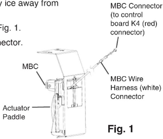
7) Press and hold the actuator paddle; check for continuity across the wires of MBC connector. When the actuator paddle is engaged, MBC switch is open. If closed, check that the actuator paddle is not restricted. Clean if necessary. See "II.D.2.b) Mechanical Bin Control Cleaning." If MBC switch still reads closed, replace MBC.
8) Reconnect MBC connector to CB K4 connector, then move the control switch to the "ICE" position. Turn on the power supply.
9) Check that CB green "BC CLOSED" LED is on.
10) Allow the icemaker to cycle on. Press and hold the actuator paddle. CB yellow "BC OPEN" LED should turn on and the icemaker should shut down according to the chart below. If it does not, replace CB.
| Cycle at Mechanical Bin Control Activation | Shutdown |
| Fill Cycle 15 sec. after activation. | |
| Harvest Cycle At the end of the harvest cycle, or up to 15 sec. into the freeze cycle if activated at the end of the harvest cycle. | |
| Freeze Cycle 15 sec. after activation if activated at least 15 sec. before the 5-min. short cycle protection timer terminates. Otherwise, at the end of the next harvest cycle. | |
Legend: MBC-mechanical bin control; CB-control board
2. Mechanical Bin Control Cleaning
Scale may build up on MBC. Scale can cause the actuator paddle and magnet to stick. In this case, MBC should be cleaned.
WARNING
CHOKING HAZARD: Ensure all components, fasteners, and thumbscrews are securely in place after the icemaker is serviced. Make sure that none have fallen into the dispense unit/ice storage bin.
1) Turn off the power supply.
2) Remove the front panel, then move the control switch to the "OFF" position.
3) Clear any ice away from MBC.
4) Disconnect MBC connector from CB K4 connector, then remove MBC from the icemaker.
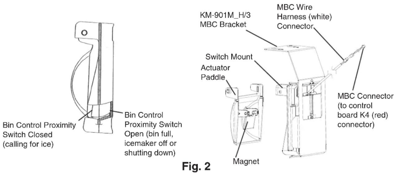
5) Remove the actuator paddle from the switch mount. See Fig. 2.
6) Wipe down MBC with a mixture of 1 part of Hoshizaki "Scale Away" and 25 parts of warm water. Rinse the parts thoroughly with clean water.
7) Reassemble MBC and replace it in its correct position.
Note: If the magnet was removed for cleaning, be sure to replace it in its correct position.
8) Reconnect MBC connector to CB K4 connector, then move the control switch to the "ICE" position.
9) Replace the control box cover in its correct position.
10) Turn on the power supply to start the automatic icemaking process.
11) Replace the front panel in its correct position.
Legend: MBC-mechanical bin control
E. Switches
Two control switches are used to control operation. These switches are referred to as the "control switch" and the "service switch" and are located on the control box.
1. Control Switch
The control switch has three positions: "OFF" for power off, "ICE" for icemaking, and "SERVICE" to activate the service switch.
2. Service Switch
When the control switch is in the "SERVICE" position, the control switch supplies power to the service switch and the machine is in service mode. The service switch has three positions: "DRAIN, "CIRCULATE," and "WASH." See the information below for details of each function.
Note:
- When the service switch is activated, power is supplied to the water pump in all three positions.
- When the control switch is in the "OFF" position or in the "ICE" position, the service switch has no power and can be left in any position.
a) DRAIN
This model utilizes a pump-out drain system. When the service switch is active and placed in the "DRAIN" position, power is supplied to the pump, service relay, and drain valve.
b) CIRCULATE
When the service switch is active and placed in the "CIRCULATE" position, power is supplied to the pump only. This operation can be used to circulate cleaner for extended periods of time over the outside surface of the evaporator.
c) WASH
This model utilizes a solenoid operated wash (bypass) valve. When the service switch is active and placed in the "WASH" position, power is supplied to the pump and the wash valve. This operation is used to circulate cleaner and sanitizer over both the inside and outside of the evaporator.
F. Float Switch Check and Cleaning
FS is used to determine that there is sufficient water in the water tank after the 1-min. fill cycle and after each harvest cycle. FS is also used to determine that the appropriate volume of water has been converted into ice before switching out of the freeze cycle. No adjustment is required.
1. Float Switch Check
To check FS, follow the steps below.
1) Remove the front panel. Disconnect the dispense solenoid wire harness and set front panel aside. Move the control switch to the "SERVICE" position, then move the service switch to the "DRAIN" position.
2) Allow the water to drain from the water tank. Move the control switch to the "OFF" position, then turn off the power supply.
3) Remove the control box cover.
4) Disconnect FS connector from CB K5 (black) connector.
5) Check for continuity across FS leads. With the water tank empty, FS should be open. If open, continue to step 6. If closed, follow the steps in "II.E.2. Float Switch Cleaning." After cleaning FS, check it again. Replace if necessary.
6) Reconnect FS connector to CB K5 connector, then replace the control box cover in its correct position.
7) Move the control switch to the "ICE" position. Turn on the power supply. After 1 min., the 1-min. fill cycle should end and the initial harvest cycle should begin. If the initial harvest cycle begins, FS is good and the check is complete. Reconnect the dispense solenoid wire harness, then replace the front panel in its correct position. If the initial harvest cycle does not begin, continue to step 8.
8) Turn off the power supply.
9) Move the control switch to the "OFF" position.
10) Remove the control box cover.
11) Disconnect FS connector from CB K5 connector.
12) Check for continuity across FS leads. With the water tank full, FS should be closed. If FS is closed and the icemaker will not switch from the 1-min. fill cycle to the initial harvest cycle, replace CB.
If FS is open, confirm that the water tank is full. If the water tank is not full, check the water supply, water filters, and inlet water valve. If the water tank is full, follow the steps in "II.E.2. Float Switch Cleaning." After cleaning FS, check it again. Replace if necessary.
13) After repair is complete, replace the control box cover, move the control switch to the "ICE" position. Reconnect the dispense solenoid wire harness, then replace the front panel in its correct position. Next, turn on the power supply.
Legend: CB-control board; FS-float switch
2. Float Switch Cleaning
Depending on local water conditions, scale may build up on FS. Scale on the switch can cause the float to stick. In this case, FS should be cleaned.
1) Remove the front panel. Disconnect the dispense solenoid wire harness and set front panel aside. Move the control switch to the "SERVICE" position, then move the service switch to the "DRAIN" position.
2) Allow the water to drain from the water tank. Move the control switch to the "OFF" position, then turn off the power supply.
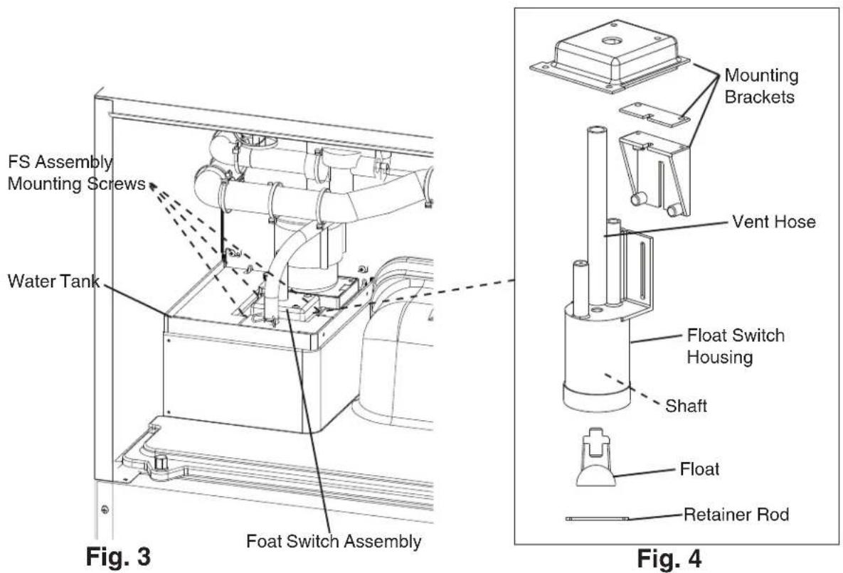
3) Remove the 3 FS assembly mounting screws and remove FS assembly from the water tank. See Fig. 3.
5) Remove the retainer rod from the bottom of FS housing, then remove the float. Be careful not to bend the retainer rod excessively when removing it. See Fig. 4.
6) Wipe down FS mounting bracktes, housing, shaft, float, and retainer rod with a mixture of 1 part Hoshizaki "Scale Away" and 25 parts warm water. Clean the inside of the vent hose with cleaning solution. Rinse the parts thoroughly with clean water.
7) Reassemble FS assembly and replace it in its correct position.
8) Move the control switch to the "ICE" position.
9) Reconnect the dispense solenoid wire harness and replace the front panel in its correct position.
10) Turn on the power supply to start the automatic icemaking process.
Legend: CB-control board; FS-float switch
G. Thermistor Check
To check thermistor resistance, follow the steps below.
1) Turn off the power supply.
2) Remove the front panel. Disconnect the dispense solenoid wire harness and set front panel aside. Move the control switch to the "OFF" position.
3) Remove the control box cover.
4) Remove the thermistor from the refrigerant tubing.
5) Immerse the thermistor sensor portion in a glass containing ice and water for 2 or 3 min.
6) Disconnect the thermistor connector from CB K3 connector and check the resistance between thermistor leads. Normal range is 4.7 to 6.2 kΩ. If outside the normal range, replace the thermistor. See "IV.B. Component Service Information." If within the normal range, continue to the next step.
7) Replace the thermistor in its correct position. See "IV.B. Component Service Information."
8) Reconnect the thermistor connector to CB K3 connector.
9) Replace the control box cover in its correct position.
10) Move the control switch to the "ICE" position.
11) Reconnect the dispense solenoid wire harness and replace the front panel in its correct position.
12) Turn on the power supply.
13) Once the harvest cycle starts (Comp energizes), begin timing the harvest cycle.
14) The harvest timer and harvest cycle should terminate within 2 to 5 min. If the harvest cycle does not terminate within 2 to 5 min., replace CB.
Legend: CB-control board; Comp-compressor
H. Diagnostic Tables
1. No Ice Production
| No Ice Production - Possible Cause | |
| 1. Power Supply a) Off, blown fuse, | or tripped breaker. |
| b) Not within specifications. | |
| 3. Fuse (control box) a) Blown or tripped. | |
| 5. Control Switch a) In "OFF" or "SERVICE" position. | |
| 6. High-Pressure Switch a) Dirty condenser. | |
| 7. Control Transformer(115VAC/10.5VAC) | a) Coil winding open or shorted. |
| 8. Control BoardSee "II.C. Control Board Check" | a) In alarm. |
| b) Yellow "BC OPEN" LED on (bin full). | |
| c) Defective. | |
| 9. Mechanical Bin ControlSee "II.D. Bin Control Check" | a) Tripped with bin filled with ice. |
| b) Actuator does not move freely. | |
| c) Defective. | |
| 10. Water Supply | a) Water supply off or improper water pressure. |
| b) External water filters clogged. | |
| 11. Inlet Water Valve | a) Screen or orifice clogged. |
| b) Coil winding open. | |
| c) Water valve open in freeze cycle. | |
| 12. Float SwitchSee "II.E. Float Switch Check and Cleaning" | a) Float does not move freely. |
| b) Defective. | |
| 13. Compressor | a) Compressor relay contacts bad or coil winding open. |
| b) Start capacitor or run capacitor defective. | |
| c) Internal protector open. | |
| d) Start relay contacts bad or coil winding open. | |
| e) Defective. | |
| 14. Hot Gas Valve | a) Closed in harvest cycle. |
| b) Open in freeze cycle. | |
| 15. ThermistorSee "II.F. Thermistor Check" | a) Loose, disconnected, or defective. |
| 16. Pump Motor | a) Motor winding open. |
| b) Bearing worn out or locked rotor. | |
| c) Defective capacitor. | |
| d) Mechanical seal worn out. | |
| 17. Thermostatic Expansion Valve | a) Bulb loose. |
| b) Operating erratically. | |
| 18. Liquid Line Valve | a) Closed in freeze cycle. |
| b) Open in harvest cycle. | |
| 19. Fan Motor a) Motor winding open | |
| b) Bearing worn out or locked rotor. | |
| c) Defective capacitor. | |
| 20. Water System (drain valve, bypass valve) | a) Water leaks causing short freeze time or freeze up. |
2. Freeze-Up
Defrost and clean the icemaker prior to diagnosing freeze-up. Fill out a freeze-up checklist. See the Hoshizaki America Technician's Pocket Guide or contact your local distributor for a copy of the freeze-up checklist.
| Freeze-Up - Possible Cause | |
| Harvest Cycle | |
| 1. Evaporator a) Scaled up. | |
| b) Damaged. | |
| 2. Cube Guides a) Out of position. | |
| b) Damaged. | |
| 3. Spray Tubes and/or Spray Guides | a) Dirty. |
| b) Out of position. | |
| 4. Water Supply a) Low water pressure. | |
| 5. Inlet Water Valve | a) Screen or orifice clogged. |
| b) Defective. | |
| 6. Float Switch See "II.E. Float Switch Check and Cleaning" | a) Dirty, sticking. |
| b) Defective. | |
| 7. Refrigerant Charge a) Low. | |
| 8. Control Board See "III.C. Settings and Adjustments" and "II.C. Control Board Check" | a) Harvest timer (S4 dip switch 1 & 2) set too short. |
| b) Harvest pump timer (S4 dip switch 7) not in factory default position. | |
| c) Defective. | |
| 9. Bin Control See "II.D. Bin Control Check" | a) Actuator does not move freely. |
| 10. Thermistor See "II.F. Thermistor Check" | a) Loose, disconnected, or defective. |
| 11. Thermostatic Expansion Valve | a) Defective. |
| 12. Hot Gas Valve | a) Closed or restricted. |
| 13. Liquid Line Valve | a) Open. |
| Freeze Cycle | |
| 1. Evaporator a) Scaled up. | |
| b) Damaged. | |
| 2. Spray Tubes and/or Spray Guides | a) Dirty. |
| b) Out of position. | |
| 3. Refrigerant Charge a) Low. | |
| 4. Control Board See "II.C. Control Board Check" | a) Freeze timer (S4 dip switch 9 & 10) set incorrectly. |
| b) Defective. | |
| 5. Inlet Water Valve a) Leaking by. | |
| 6. Float Switch See "II.E. Float Switch Check and Cleaning" | a) Float does not move freely. |
| b) Defective. | |
| 7. Pump Motor a) RPM too slow. | |
| b) Impeller damaged. | |
| 8. Thermostatic Expansion Valve | a) Bulb loose or defective. |
| 9. Liquid Line Valve a) Restricted. | |
3. Low Ice Production
| Low Ice Production - Possible Cause | |
| Long Harvest Cycle | |
| 1. Evaporator a) Scaled up. | |
| 2. Spray Tubes and/or Spray Guides | a) Dirty. |
| b) Out of position. | |
| 3. Refrigerant Charge a) Low. | |
| 4. Water Supply a) Low water pressure. | |
| 5. Control BoardSee "II.C. Control Board Check" | a) Thermistor connection loose (K3). |
| b) Defective. | |
| 6. ThermistorSee "II.F. Thermistor Check" | a) Loose, disconnected, or defective. |
| 7. Hot Gas Valve | a) Erratic or closed. |
| 8. Inlet Water Valve | a) Screen or orifice clogged. |
| 9. Compressor a) Inefficient or off. | |
| 10. Liquid Line Valve | a) Erratic or open. |
| 11. Thermostatic Expansion Valve | a) Defective. |
| Long Freeze Cycle | |
| 1. Evaporator a) Scaled up, dirty. | |
| 2. Float SwitchSee "II.E. Float Switch Check and Cleaning" | a) Scaled up, dirty. |
| b) Float sticking. | |
| c) Defective switch. | |
| 3. Inlet Water Valve a) Leaking by. | |
| 4. Hot Gas Valve a) Erratic or open. | |
| 5. Condenser a) Clogged. | |
| 6. Control BoardSee "II.C. Control Board Check" | a) Float switch connection loose (K5). |
| b) Defective. | |
| 7. Refrigerant Charge a) Low. | |
| 8. Thermostatic Expansion Valve a) | Bulb loose. |
| b) Defective. | |
| 9. Compressor a) Inefficient or off. | |
| 10. Pump Motor a) RPM too slow. | |
| 11. Liquid Line Valve | a) Erratic or restricted. |
III. Controls and Adjustments
- A Hoshizaki exclusive control board is employed in KM series appliances.
- All models are pretested and factory adjusted.
- For a control board check procedure, see "II.C. Control Board Check."
NOTICE
- Fragile, handle very carefully.
- The control board contains integrated circuits, which are susceptible to failure due to static discharge. It is especially important to touch the metal part of the icemaker when handling or replacing the control board.
- Do not touch the electronic devices on the control board or the back of the control board.
- Do not change wiring and connections. Do not misconnect K3 WHITE, K4 RED, and K5 BLACK, because the same connector is used for the thermistor, mechanical bin control, and float switch.
- Do not short out power supply to test for voltage.
- Always replace the whole control board assembly if it goes bad.
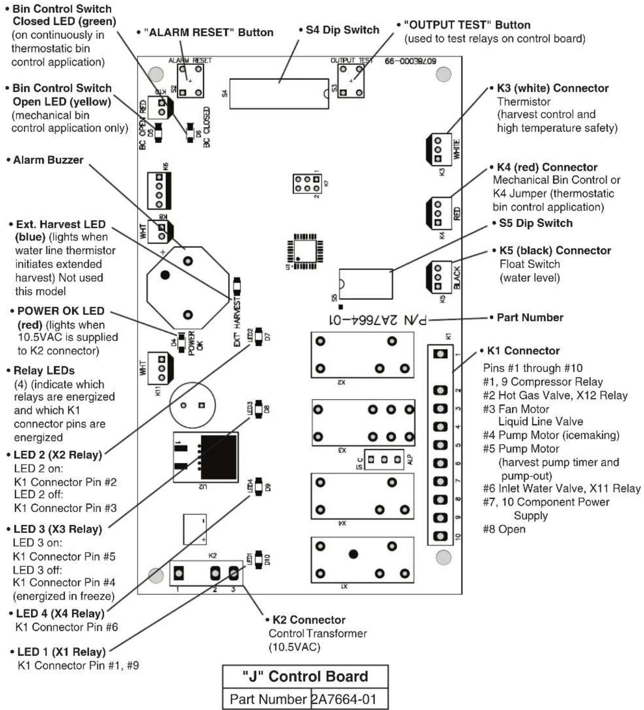
A. Control Board Layout
"J" Control Board
B. LED Lights and Audible Alarm Safeties
At startup, a 5-second delay occurs while the control board conducts an internal timer check. A beep occurs when the control switch is moved to the "ICE" position. The red "POWER OK" LED indicates proper control voltage and remains on unless a control voltage problem occurs. The green LEDs 1 through 4 energize and sequence from initial startup as listed in the table below. Note that the order of the LEDs from the outer edge of the control board is 1, 4, 3, 2.
| Sequence Step LED | Energized Components | Time LEDs are On | |||
| Min. Max. Avg. | |||||
| 1-Minute Fill Cycle 4 WV 1 minute | |||||
| Harvest Cycle | 1, 4, 2 | Comp, HGV, WV | 2 minutes | 20 minutes | 3 to 5 minutes |
| Harvest Pump Timer | 1, 3, 2 | Comp, HGV, PM | 0 seconds | 50 seconds | harvest pump timer setting |
| Freeze Cycle | 1 Comp, FM, PM, LLV | 5 minutes freeze timer setting | 30 to 35 minutes | ||
| Pump-Out Cycle | 1, 4*, 3, 2 | Comp, HGV, PM, WV* | 10 seconds | 20 seconds | *pump-out timer setting |
The built-in safeties shut down the icemaker and have alarms as listed below.
| No. of Beeps (every 3 sec.) | Type of Alarm | Notes |
| 1 | High Evaporator Temp. (temperature > 127°F) (53°C) | Check for harvest problem (stuck HGV or relay), hot water entering icemaker, or shorted thermistor. |
| 2 | Harvest Backup Timer (harvest > 20 min. for two cycles in a row) | Check for open thermistor, HGV not opening, TXV or LLV leaking by, low charge, or inefficient Comp, or WRV leaking by. |
| 3 | Freeze Timer (freeze > freeze timer setting for two cycles in a row) | Check for FS stuck closed (up), WV leaking by, HGV leaking by, PM not pumping, TXV not feeding properly, LLV not opening, low charge, HM not bypassing, or inefficient Comp. |
| To reset the above safeties, press the "ALARM RESET" button with the power supply on. | ||
| 6 | Low Voltage (92VAC±5% or less) | Red LED turns off if voltage protection operates. The control voltage safeties automatically reset when voltage is corrected. |
| 7 | High Voltage (147VAC±5% or more) | |
Legend: Comp-compressor; FM-fan motor; FS-float switch; HGV-hot gas valve; LLV-liquid line valve; PM-pump motor; TXV-thermostatic expansion valve; WRV-water regulating valve; WV-inlet water valve
C. Settings and Adjustments
NOTICE
Dip switches are factory set. Failure to maintain factory settings may adversely affect performance and warranty coverage. For more information, contact your Hoshizaki Service Center.
1. Default Dip Switch Settings
The dip switches are factory-adjusted to the following positions for the "J" control board:
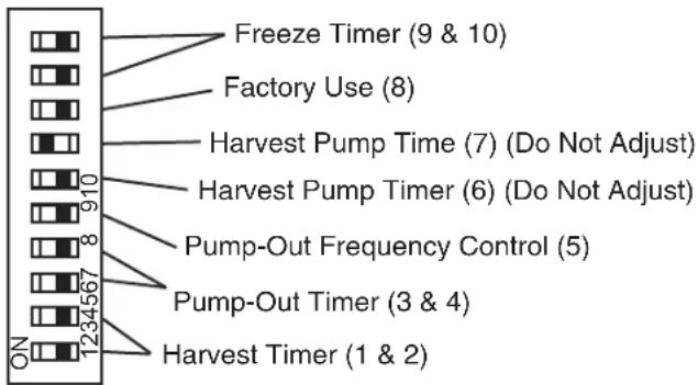
| S4 Dip Switch No. 1 2 | 3 4 5 | 6 7 8 | 9 10 | |||||||
| All Models OFF OFF O | FF OFF | FF OFF | FF ON | OFF | OFF | OFF |
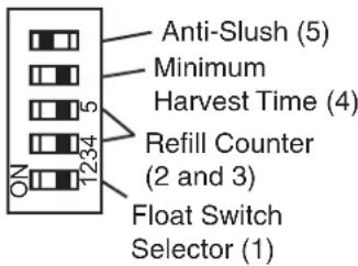
| S5 Dip Switch (Do Not Adjust)"J" Control Board | |||||
| Dip Switch No. | 1 2 | 3 4 5 | |||
| All Models OFF OFF | OFF | OFF | ON | ||
S4 Dip Switch
"J" Control Board
flowchart
graph TD
    A["ON"] --> B["1234567"]
    B --> C["Pump-Out Timer (3 & 4)"]
    C --> D["Pump-Out Frequency Control (5)"]
    D --> E["910"]
    E --> F["Harvest Pump Timer (6) (Do Not Adjust)"]
    F --> G["910"]
    G --> H["Harvest Pump Time (7) (Do Not Adjust)"]
    H --> I["8"]
    I --> J["Factory Use (8)"]
    J --> K["9 & 10"]
    K --> L["Freeze Timer (9 & 10)"]
S5 Dip Switch (Do Not Adjust)
"J" Control Board
2. Harvest Timer (S4 dip switch 1 & 2)
The harvest timer starts counting when the thermistor reaches 48^ F ( 9^ C) at the evaporator outlet and the control board reads 3.9 k from the thermistor. The harvest timer is factory set, and generally no adjustment is required. However, a setting longer than the factory setting may be advised in cases where the drain provided at harvest needs to be prolonged for extra cleaning. Before changing this setting, contact Hoshizaki Technical Support at 1-800-233-1940 for recommendations. Keep in mind that setting the harvest timer to a longer setting decreases 24-hour production.
Note that the pump-out timer (S4 dip switch 3 & 4) acts in place of the harvest timer during cycles with a pump out. For details, see "III.C.3. Pump-Out Timer (S4 dip switch 3 & 4)."
Note: On models with a pump-out every cycle, the harvest timer is only relevant during the initial harvest cycle since a pump out occurs every cycle thereafter.
| S4 Dip Switch Setting | Time (sec.) | |
| No. 1 | No. 2 | |
| OFF | OFF | 60 |
| ON | OFF | 90 |
| OFF | ON | 120 |
| ON | ON | 180 |
3. Pump-Out Timer (S4 dip switch 3 & 4)
| NOTICE |
| Do not adjust 3 off and 4 on. Drain valve does not energize in this setting. |
When a pump-out is called for, the pump motor stops for 2 sec. After 2 sec. the drain valve and pump motor energize. The pump motor drains the water tank for the time determined by the pump-out timer. The pump-out timer also acts in place of the harvest timer during cycles with a pump-out. The pump-out timer is factory set, and generally no adjustment is required. However, where water quality is bad and the icemaker needs a longer pump-out time, the pump-out timer can be adjusted. The pump-out timer control can be set to pump-out for 10 or 20 sec.
| S4 Dip Switch Setting | Time (sec.) | Inlet Water ValveNo. 3 | ||
| T1 | T2 | |||
| OFF OFF | 10 150 Closed | |||
| ON OFF | 10 180 Closed | |||
| OFF ON | 10 120 Open | |||
| ON ON | 20 180 Closed | |||
No. 4
T1: Time to drain the water tank
T2: Harvest timer at pump out
4. Pump-Out Frequency Control (S4 dip switch 5)
The pump-out frequency control is factory set to drain the water tank every 10 cycles. Generally no adjustment is required. However, where water quality is bad and the icemaker needs a pump-out more often, the pump-out frequency can be adjusted. The pump-out frequency control can be set to have a pump-out occur every cycle, or every 2, 5, or 10 cycles.
The first pump-out is dependent on S4 dip switch 5. See the table below.
| S4 Dip Switch Setting | Pump-Out Frequency | 1st Pump-Out |
| No. 5 | ||
| OFF Every 10 | cycles After 11th freeze cycle | |
| ON | Every cycle | After 2nd freeze cycle |
5. Harvest Pump Time (S4 dip switch 6)
| NOTICE |
| Factory set for proper operation. Do not adjust. Adjustment outside of the factory default setting may result in damage to the appliance. |
The harvest pump time starts with 50 sec. left to go in the harvest time (S4 dip switches 1 & 2) after the thermistor reaches 48^ F ( 9^ C) at the evaporator outlet and the control board reads 3.9 kΩ from the thermistor. The harvest pump time is factory set, and no adjustment is required.
| S5 Dip Switch Setting | Harvest Pump Time |
| No. 6 | |
| OFF 50 sec. | |
| ON 25 sec. |
6. Harvest Pump Time Operation (S4 dip switch 7)
S4 dip switch 7 is used for harvest pump timer operation.
| NOTICE |
| Factory set for proper operation. Do not adjust. Adjustment outside of the factory default setting may result in damage to the appliance. |
Depending on the harvest pump time operation setting, the pump motor either stays off or is energized the last 50 seconds of harvest. When the pump motor is energized, water circulates over the evaporator. The inlet water valve is open during harvest for a maximum of 6 minutes or the length of harvest minus 0 or 50 sec. (determined by the harvest pump time setting), whichever is shorter.
When S4 dip switch 7 is in the on position and harvest begins, X10, X11, and X12 relays energize. A latching circuit is created through the X11 and X10 relays. For further details, see "VIII.C. Wiring Diagrams." 50 sec. before harvest termination, LED 4 turns off, inlet water valve and X11 relay de-energize. X10 relay remains energized through the latching circuit and X12 relay remains energized through the pink (P) wire. Next, LED 3 turns on and control board K1 connector pin #5 (DBU) wire energizes, energizing the pump motor through the X12 relay for the last 50 sec. of harvest.
| "J" Control Board | |
| S4 Dip Switch Setting | Pump Motor Time (sec.) |
| No. 7 | |
| OFF Disabled | |
| ON Enabled | |
7. Factory Use (S4 dip switch 8)
Factory set for proper operation. Do not adjust. This must be left in the factory default position.
8. Freeze Timer (S4 dip switch 9 & 10)
| NOTICE |
| Adjust to proper specification, or the icemaker may not operate correctly. |
The freeze timer setting determines the maximum allowed freeze time to prevent possible freeze-up issues. Upon termination of the freeze timer, the control board initiates the harvest cycle or pump-out cycle. After 2 consecutive freeze timer terminations, the control board shuts down the icemaker. In this case, see "II.G.3. Low Ice Production" for possible solutions. The freeze timer is factory set and no adjustment is required. Before changing this setting, contact Hoshizaki Technical Support at 1-800-233-1940 for recommendations.
| S4 Dip Switch Setting | Time (min.) | |
| No. 9 No. 10 | ||
| OFF OFF 60 | ||
| ON OFF 70 | ||
| OFF ON 50 | ||
| ON ON 85 | ||
9. Float Switch Selector (S5 dip switch 1)
This dip switch setting allows use of this control board in single and dual float switch models. This model uses a single float switch style.
| NOTICE |
| Do not adjust. This must be left in the factory default position or the icemaker will not operate correctly. |
| S5 Dip Switch Setting | Top or Bottom Float Switch ControlNo. 1 |
| OFF Bottom Float | Float Switch Enabled |
| ON Top Float | Switch Enabled |
10. Refill Counter (S5 dip switch 2 and 3)
| NOTICE |
| Do not adjust. These must be left in the factory default position or the icemaker will not operate correctly. This model does not utilize refill. |
| S5 Dip Switch Setting | Refill Counter | |
| No. 2 | No. 3 | |
| OFF OFF | 0 | |
| ON OFF | 9 refills | |
| OFF ON | 1 refill | |
| ON ON | 10 refills | |
11. Minimum Harvest Time (S5 dip switch 4)
| NOTICE |
| Factory set for proper operation. Do not adjust. Adjustment outside of the factory default setting may result in damage to the appliance. |
| S5 Dip Switch Setting | Minimum Harvest TimeNo. 4 |
| OFF 120 sec. | |
| ON 70 sec. |
12. Anti-Slush (S5 dip switch 5)
This dip switch setting provides anti-slush control during the freeze cycle. When the evaporator temperature reaches 36^ F ( 2.2^ C) the control board reads a 5.8k signal from the thermistor and de-energizes the water pump for 10 sec. to melt the ice slush and prevent the ice slush from blocking the water supply tubing, causing irregular freeze patterns.
| NOTICE |
| Factory set for proper operation. Do not adjust. Adjustments outside of the factory default setting may result in damage to the appliance and may adversely affect performance and warranty coverage. |
| S5 Dip Switch Setting | Anti-SlushNo. 5 |
| OFF Disabled | |
| ON Enabled |
IV. Refrigeration Circuit and Component Service Information
WARNING
- This appliance should be diagnosed and repaired only by qualified service personnel to reduce the risk of death, electric shock, serious injury, or fire.
- Move the control switch to the "OFF" position and turn off the power supply. Place the disconnect in the "OFF" position. Lockout/Tagout to prevent the power supply from being turned back on inadvertently.
- CHOKING HAZARD: Ensure all components, fasteners, and thumbscrews are securely in place after the icemaker is serviced. Make sure that none have fallen into the dispenser unit/ice storage bin.
- Make sure all food zones in the icemaker and dispenser unit/ice storage bin are clean after service.
A. Refrigeration Circuit Service Information
WARNING
- Repairs requiring the refrigeration circuit to be opened must be performed by properly trained and EPA-certified service personnel.
- Use an electronic leak detector or soap bubbles to check for leaks. Add a trace of refrigerant to the system (if using an electronic leak detector), and then raise the pressure using nitrogen gas (140 PSIG). Do not use R-404A as a mixture with pressurized air for leak testing.
NOTICE
- Always recover the refrigerant and store it in an approved container. Do not discharge the refrigerant into the atmosphere.
- Do not leave the system open for longer than 15 min. when replacing or servicing parts. The Polyol Ester (POE) oils used in R-404A applications can absorb moisture quickly. Therefore it is important to prevent moisture from entering the system when replacing or servicing parts.
- Always install a new drier every time the sealed refrigeration system is opened. Do not replace the drier until after all other repair or replacement has been made. Install the new drier with the arrow on the drier in the direction of the refrigerant flow.
- When brazing, protect the drier by using a wet cloth to prevent the drier from overheating. Do not allow the drier to exceed 250^ (121°C).
1. Refrigerant Recovery
The icemaker is provided with refrigerant access valves. Using proper refrigerant practices, recover the refrigerant. Store the refrigerant in an approved container. Do not discharge the refrigerant into the atmosphere.
2. Brazing
WARNING
- R-404A itself is not flammable at atmospheric pressure and temperatures up to 176°F (80°C).
- R-404A itself is not explosive or poisonous. However, when exposed to high temperatures (open flames), R-404A can be decomposed to form hydrofluoric acid and carbonyl fluoride both of which are hazardous.
- Do not use silver alloy or copper alloy containing arsenic.
1) Braze all fittings while purging with nitrogen gas flowing at a pressure of 3 to 4 PSIG. Note: Because the pipes in the evaporator case are specially coated to resist corrosion, it is important to make connections outside the evaporator case when possible. If it is necessary to braze inside the evaporator case, use sandpaper to remove the coating from the brazing connections before unbrazing the components.
NOTICE
- Always install a new drier every time the sealed refrigeration system is opened.
- Do not replace the drier until after all other repair or replacement has been made. Install the new drier with the arrow on the drier in the direction of the refrigerant flow.
- When brazing, protect the drier by using a wet cloth to prevent the drier from overheating. Do not allow the drier to exceed 250^ (121°C).
2) Use an electronic leak detector or soap bubbles to check for leaks. Add a trace of refrigerant to the system (if using an electronic leak detector), and then raise the pressure using nitrogen gas (140 PSIG). Do not use R-404A as a mixture with pressurized air for leak testing.
3. Evacuation and Recharge (R-404A)
1) Attach a vacuum pump to the system. Be sure to connect the charging hoses to both high and low-side refrigerant access valves.
IMPORTANT
The vacuum level and vacuum pump may be the same as those for current refrigerants. However, the rubber hose and gauge manifold to be used for evacuation and refrigerant charge should be exclusively for POE oils.
2) Turn on the vacuum pump. Open the gauge manifold valves. Never allow the oil in the vacuum pump to flow backwards.
3) Allow the vacuum pump to pull down to a 29.9" Hg vacuum. Evacuating period depends on pump capacity.
4) Close the low-side valve and high-side valve on the gauge manifold.
5) Disconnect the gauge manifold hose from the vacuum pump and attach it to a refrigerant service cylinder. Remember to loosen the connection and purge the air from the hose. For the required refrigerant charge, see the rating label inside the icemaker. Hoshizaki recommends only virgin refrigerant or reclaimed refrigerant which meets ARI Standard 700 (latest edition) be used.
6) A liquid charge is required when charging an R-404A system (to prevent fractionation). Place the service cylinder on the scales; if the service cylinder is not equipped with a dip tube, invert the service cylinder, then place it on the scales. Open the high-side valve on the gauge manifold.
7) Allow the system to charge with liquid until the proper charge weight is met.
8) If necessary, add any remaining charge to the system through the low-side. NOTICE! To prevent compressor damage, use a throttling valve or liquid dispensing device to add the remaining liquid charge through the low-side refrigerant access valve with the icemaker running.
9) Close the high and low-side gauge manifold valves, then disconnect the gauge manifold hoses.
10) Cap the refrigerant access valves to prevent a possible leak.
B. Component Service Information
| NOTICE |
| When replacing a component listed below, see the notes to help ensure proper operation. |
| Component Notes | |
| Compressor Install | a new start capacitor, run capacitor, and start relay. |
| Thermostatic Expansion Valves | Attach the thermostatic expansion valve bulb to the suction line in the same location as the previous bulb.The bulb should be between the 10 and 2 o'clock positions on the tube.Secure the bulb with the clamp and holder, then insulate it. |
| Hot Gas Valves Liquid Line Valves | Replace the strainer if applicable.Use copper tube of the same diameter and length when replacing valve lines. |
| Fan Motors Install | a new capacitor. |
| Pump Motor Install | a new capacitor. |
| Thermistor • Attach | the new thermistor to the suction line in the same location as the previous thermistor.The thermistor should be at the 12 o'clock position on the tube.Smoothly fill the recessed area of the thermistor holder with high thermal conductive type sealant. Hoshizaki America part number 4A0683-01 (Silicone Heat Sink Compound 10-8108 manufactured by GC Electronics), KE-4560 RTV (manufactured by ShinEtsu Silicones), or equivalent are recommended.Secure the thermistor with the holder, then insulate it.Be very careful to prevent damage to the leads. |
C. Water Regulating Valve Adjustment (water-cooled model)
The water regulating valve is factory set, and generally no adjustment is required. However, when necessary, adjust the water regulator using the following procedure.
1) Prepare a thermometer to check the condenser drain temperature. Attach a pressure gauge to the high-side line of the system.
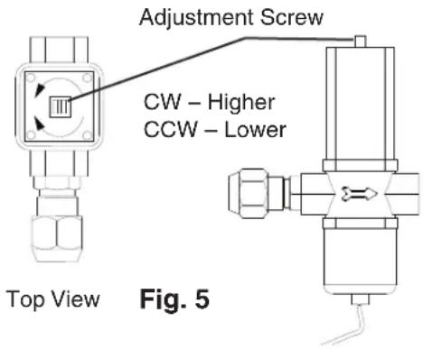
2) 5 min. after a freeze cycle starts, confirm that the thermometer reads 104^ F to 115^ F ( 40^ C to 46^ C). If it does not, rotate the adjustment screw by using a flat blade screwdriver until the temperature is in the proper range. See Fig. 5. Next, check that the reference pressure is in the range indicated in the Head Pressure table in the Performance Data section. If it is not in the proper range, verify the refrigerant charge.
3) Check that the condenser drain temperature is stable.
V. Maintenance
The maintenance schedule below is a guideline. More frequent maintenance may be required depending on water quality, the appliance's environment, and local sanitation regulations
WARNING
- Only qualified service technicians should service the appliance.
- To reduce the risk of electric shock, do not touch the control switch or service switch with damp hands
- Before servicing: Move the control switch to the "OFF" position and turn off the power supply. Place the disconnect in the "OFF" position. Lockout/Tagout to prevent the power supply from being turned back on inadvertently.
- CHOKING HAZARD: Ensure all components, fasteners, and thumbscrews are securely in place after any maintenance is done to the icemaker. Make sure that none have fallen into the dispenser unit/ice storage bin.
| Maintenance Schedule | ||
| Frequency | Area Task | |
| Daily Scoop | Clean the ice scoop | using a neutral cleaner. Rinse thoroughly after cleaning. |
| Bi-Weekly Air Filters Inspect. Wash with warm water and neutral cleaner if dirty. | ||
| Monthly External Water Filters | Internal Water Filters | Check for proper pressure and change if necessary. |
| Icemaker Exterior | Wipe down with a clean, soft cloth. Use a damp cloth containing a neutral cleaner to wipe off oil or dirt build up. Clean any chlorine staining (rust colored spots) using a non-abrasive cleanser. | |
| Underside of Icemaker and Top Kits; Bin Door and Snout | Wipe down with a clean cloth and warm water. | |
| Yearly Icemaker and Dispenser Unit/Ice Storage Bin Liner | Clean and sanitize per the cleaning and sanitizing instructions provided in the instruction manual or maintenance label on the icemaker. | |
| Water Supply Inlet | Close the icemaker water supply line shut-off valve and drain the water system. Clean the water supply inlet screen. | |
| Condenser Inspect | Clean if necessary by using a brush or vacuum cleaner. More frequent cleaning may be required depending on location. | |
| Water Hoses | Inspect the water hoses and clean/replace if necessary. | |
VI. Preparing the Appliance for Periods of Non-Use
NOTICE
- When storing the appliance for an extended time or in sub-freezing temperatures, follow the instructions below to prevent damage.
- To prevent damage to the water pump, do not operate the appliance with the control switch in the "WASH" position when the water tank is empty.
When the appliance is not used for two or three days under normal conditions, it is sufficient to move the control switch to the "OFF" position. When storing the appliance for an extended time or in sub-freezing temperatures, follow the instructions below.
1. Remove the water from the icemaker water line:
1) Turn off the power supply, then remove the front panel. Disconnect the dispense solenoid wire harness and set the front panel aside.
2) Move the control switch on the control box to the "OFF" position.
3) Close the icemaker water supply line shut-off valve and open the icemaker water supply line drain valve.
4) Allow the line to drain by gravity.
5) Attach a compressed air or carbon dioxide supply to the icemaker water supply line drain valve.
6) Make sure at least 3 min. have elapsed since you turned off the power supply. Make sure the control switch is in the "ICE" position.
7) Replace the front panel in its correct position, then turn on the power supply.
8) Blow the icemaker water supply line out using the compressed air or carbon dioxide supply.
2. Remove the water from the water tank:
1) Turn off the power supply, then remove the front panel.
2) Move the service switch to the "DRAIN" position, then move the control switch to the "SERVICE" position.
3) Replace the front panel in its correct position, then turn on the power supply for 2 minutes.
4) After 2 min., turn off the power supply, then remove the front panel.
5) Move the control switch to the "OFF" position.
6) Reconnect the dispense solenoid wire harness and replace the front panel in its correct position.
7) Turn on the power supply and dispense all ice from the icemaker. After dispensing all of the ice, turn off the power supply.
8) Close the icemaker water supply line drain valve.
3. On water-cooled model, remove the water from the water-cooled condenser:
1) Make sure the power supply is off, then remove the front panel. Disconnect the dispense solenoid wire harness and set front panel aside. Remove the left side panel.
2) Close the condenser water supply line shut-off valve. If connected to a closed loop system, also close the condenser return line shut-off valve.
3) Open the condenser water supply line drain valve. If connected to a closed loop system, also open the condenser return line drain valve.
4) Attach a compressed air or carbon dioxide supply to the condenser water supply line drain valve.
5) Open the water regulating valve by using a screwdriver to pry up on the spring retainer underneath the spring. While holding the valve open, blow out the condenser using the compressed air or carbon dioxide supply until water stops coming out.
6) Close the drain valve(s).
7) Replace the left side panel in its correct position, then reconnect the dispense solenoid wire harness and replace the front panel in its correct position.
VII. Disposal
The appliance contains refrigerant and must be disposed of in accordance with applicable national, state, and local codes and regulations. Refrigerant must be recovered by properly certified service personnel.
VIII. Technical Information
We reserve the right to make changes in specifications and design without prior notice.
A. Specification and Performance Data Sheets
Pressure data is recorded at 5 min. into freezing cycle. The data not in bold should be used for reference only.
1. DKM-500BAJ
Specification Sheet
| AC SUPPLY VOLTAGE 115/60/1 | |
| AMPERAGE 13.5 A (5 Min. Freeze AT 104°F / WT 80°F) | |
| MINIMUM CIRCUIT AMPACITY 20 A | |
| MAXIMUM FUSE SIZE 20 A | |
| ELECTRIC & WATER CONSUMPTION 90/70°F 70/50°F | |
| ELECTRIC W (kWH/100 lbs.) 1240(5.56) 1130(4.98) | |
| WATER gal./24HR (gal./100 lbs.) 89(16.6) 202(37.0) | |
| ICE PRODUCTION PER CYCLE | 7.2 lbs. (3.3 kg) 360pcs. |
| APPROXIMATE STORAGE CAPACITY | 140 lbs. (64 kg) |
| APPROXIMATE ICE DISPENSE RATE | 13 lbs/min. (6 kg/min) |
| BIN CONTROL SYSTEM | Proximity Switch with Delay |
| REFRIGERANT CHARGE | R404A, 1 lb. 12.2 oz. (800g) |
Performance Data Sheet
| APPROXIMATE ICE PRODUCTION PER 24 HR. | AMBIENT TEMP.(°F/°C) | WATER TEMP. (°F/°C) | |||||
| 50/10 | 70/21 | 90/32 | |||||
| 70/21 | 545 | 247 | 542 | 246 | 536 | 243 | |
| Ibs./day kg./day | 100/38 | 540 | 245 | 533 | 242 | 523 | 237 |
| APPROXIMATE ELECTRIC | 70/21 | 1130 | 1162 | 1177 | |||
| CONSUMPTION | 80/27 | 1155 | 1205 | 1203 | |||
| 90/32 | 1162 | 1240 | 1245 | ||||
| watts | 100/38 | 1155 | 1241 | 1250 | |||
| APPROXIMATE WATER | 70/21 | 202 | 0.76 | 169 | 0.64 | 156 | 0.59 |
| CONSUMPTION PER 24 HR. | 80/27 | 176 | 0.67 | 125 | 0.47 | 130 | 0.49 |
| 90/32 | 169 | 0.64 | 89 | 0.34 | 86 | 0.33 | |
| gal./day m3/day | 100/38 | 133 | 0.50 | 88 | 0.33 | 84 | 0.32 |
| FREEZING CYCLE TIME | 70/21 | 15 | 16 | 17 | |||
| 80/27 | 16 | 17 | 18 | ||||
| 90/32 | 16 | 18 | 19 | ||||
| min. | 100/38 | 16 | 18 | 20 | |||
| HARVEST CYCLE TIME | 70/21 | 3.5 | 3.1 | 2.9 | |||
| 80/27 | 3.2 | 2.6 | 2.6 | ||||
| 90/32 | 3.1 | 2.1 | 2.1 | ||||
| min. | 100/38 | 2.6 | 2.1 | 2.1 | |||
| HEAD PRESSURE | 70/21 | 242 | 17.0 | 263 | 18.5 | 295 | 20.7 |
| 80/27 | 258 | 18.1 | 290 | 20.4 | 324 | 22.8 | |
| 90/32 | 263 | 18.5 | 313 | 22.0 | 347 | 24.4 | |
| PSIG kg/cm2G | 100/38 | 270 | 19.0 | 321 | 22.6 | 378 | 26.6 |
| SUCTION PRESSURE | 70/21 | 51 | 3.6 | 53 | 3.7 | 54 | 3.8 |
| 80/27 | 53 | 3.7 | 56 | 3.9 | 56 | 3.9 | |
| 90/32 | 53 | 3.7 | 58 | 4.1 | 59 | 4.1 | |
| PSIG kg/cm2G | 100/38 | 53 | 3.7 | 58 | 4.1 | 59 | 4.1 |
| TOTAL HEAT OF REJECTION FROM CONDENSER | 9,100 BTU/h [AT 90°F (32°C) / WT 70°F (21°C)] | ||||||
| TOTAL HEAT OF REJECTION FROM COMPRESSOR | 1,700 BTU/h [AT 90°F (32°C) / WT 70°F (21°C)] | ||||||
2. DKM-500BWJ
Specification Sheet
| AC SUPPLY VOLTAGE 115/60/1 | |
| AMPERAGE 12 A (5 Min. Freeze AT 104°F / WT 80°F) | |
| MINIMUM CIRCUIT AMPACITY 20 A | |
| MAXIMUM FUSE SIZE 20 A | |
| ELECTRIC & WATER CONSUMPTION 90/70°F 70/50°F | |
| ELECTRIC W (kWH/100 lbs.) 1000(4.79) 960(4.26) | |
| WATER gal./24HR (gal./100 lbs.) 90(18.0) 126(23.4) | |
| WATER COOLED CONDENSER 515(103) 266(49) | |
| gal./24HR (gal./100 lbs.) | |
| ICE PRODUCTION PER CYCLE 7.2 lbs. (3.3 kg) 360pcs. | |
| APPROXIMATE STORAGE CAPACITY 140 lbs. (64 kg) | |
| APPROXIMATE ICE DISPENSE RATE | 13 lbs/min. (6 kg/min) |
| BIN CONTROL SYSTEM | Proximity Switch with Delay |
| REFRIGERANT CHARGE | R404A, 1 lb. 2 oz. (510g) |
Performance Data Sheet
| APPROXIMATE ICE PRODUCTION PER 24 HR. | AMBIENT TEMP.(°F/°C) | WATER TEMP. (°F/°C) | |||||
| 50/10 | 70/21 | 90/32 | |||||
| 70/21 | 540 | 245 | 528 | 240 | 509 | 231 | |
| 80/27 | 531 | 241 | 513 | 233 | 492 | 223 | |
| 90/32 | 528 | 240 | 500 | 227 | 479 | 217 | |
| Ibs./day kg./day | 100/38 | 523 | 237 | 495 | 225 | 460 | 209 |
| APPROXIMATE ELECTRIC | 70/21 | 960 | 972 | 983 | |||
| CONSUMPTION | 80/27 | 969 | 987 | 996 | |||
| 90/32 | 972 | 1000 | 1010 | ||||
| watts | 100/38 | 973 | 1002 | 1020 | |||
| APPROXIMATE WATER CONSUMPTION | 70/21 | 393 | 1.49 | 455 | 1.72 | 549 | 2.08 |
| PER 24 HR. | 80/27 | 440 | 1.67 | 537 | 2.03 | 635 | 2.41 |
| 90/32 | 455 | 1.72 | 605 | 2.29 | 704 | 2.66 | |
| gal./day m3/day | 100/38 | 552 | 2.09 | 628 | 2.38 | 794 | 3.01 |
| FREEZING CYCLE TIME | 70/21 | 18 | 18 | 19 | |||
| 80/27 | 18 | 19 | 19 | ||||
| 90/32 | 18 | 19 | 20 | ||||
| min. | 100/38 | 18 | 19 | 21 | |||
| HARVEST CYCLE TIME | 70/21 | 2.6 | 2.4 | 2.4 | |||
| 80/27 | 2.5 | 2.2 | 2.3 | ||||
| 90/32 | 2.4 | 2.1 | 2.0 | ||||
| min. | 100/38 | 2.3 | 2.0 | 2.0 | |||
| HEAD PRESSURE | 70/21 | 278 | 19.5 | 280 | 19.7 | 283 | 19.9 |
| 80/27 | 280 | 19.7 | 283 | 19.9 | 286 | 20.1 | |
| 90/32 | 280 | 19.7 | 285 | 20.0 | 289 | 20.3 | |
| PSIG kg/cm2G | 100/38 | 281 | 19.8 | 286 | 20.1 | 292 | 20.5 |
| SUCTION PRESSURE | 70/21 | 53 | 3.7 | 54 | 3.8 | 55 | 3.8 |
| 80/27 | 53 | 3.8 | 54 | 3.8 | 55 | 3.9 | |
| 90/32 | 54 | 3.8 | 55 | 3.9 | 56 | 3.9 | |
| PSIG kg/cm2G | 100/38 | 54 | 3.8 | 55 | 3.9 | 57 | 4.0 |
| TOTAL HEAT OF REJECTION FROM CONDENSER | 7,700 BTU/h [AT 90°F (32°C) / WT 70°F (21°C)] |
| TOTAL HEAT OF REJECTION FROM COMPRESSOR | 1,400 BTU/h [AT 90°F (32°C) / WT 70°F (21°C)] |
| WATER FLOW FOR CONDENSER | 30 gal./h [AT 100°F (38°C) / WT 90°F (32°C)] |
| PRESSURE DROP OF COOLING WATER LINE | less than 10 PSIG |
B. Wiring Diagram
1. DKM-500B\_J
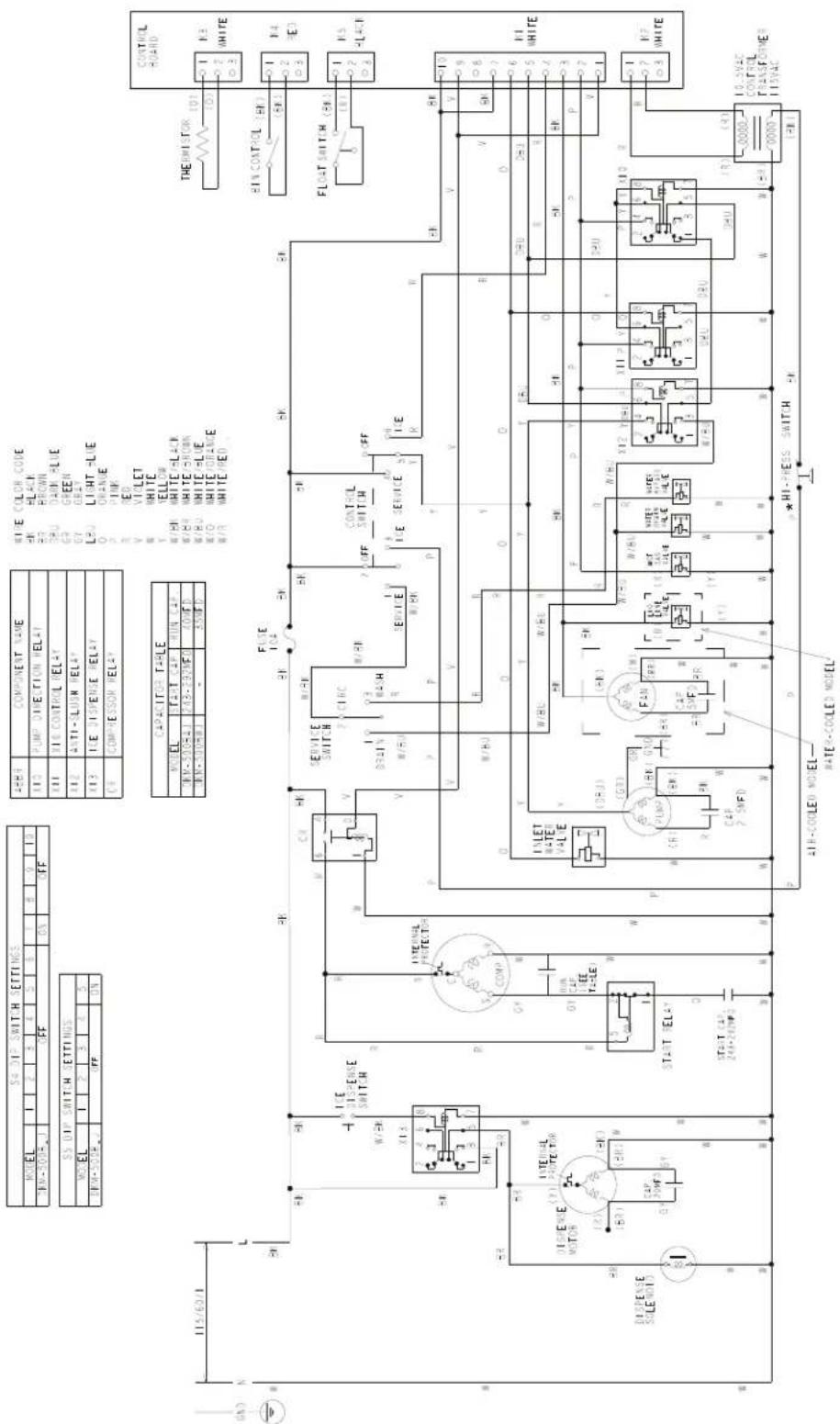
| * High-Pressure Switch | ||
| Air-Cooled Model W | Water-Cooled Model | |
| Cut-out | 412± 22 \ 0 PSIG 384 | ± 22 \ 0 PSIG |
| Cut-in | 327±22 PSIG 284±22 | PSIG |
- WARNING
- IMPORTANT
- CONTENTS
- Important Safety Information
- ⚠ WARNING, continued
- NOTICE
- Construction and Water/Refrigeration Circuit Diagram
- Construction
- Water/Refrigeration Circuit Diagram
- Air-Cooled Models (BAJ)
- Sequence of Operation and Service Diagnosis
- Sequence of Operation Flow Chart
- Service Diagnosis
- Diagnosis
- IMPORTANT! S4 dip switch 7 must remain on. Otherwise, PM will not energize during the last 50 sec. of harvest.
- Mechanical Bin Control:
- Control Board Check
- Bin Control Check
- Mechanical Bin Control Check
- Mechanical Bin Control Cleaning
- Switches
- Control Switch
- Service Switch
- a) DRAIN
- b) CIRCULATE
- c) WASH
- Float Switch Check and Cleaning
- Float Switch Check
- Float Switch Cleaning
- Thermistor Check
- Diagnostic Tables
- No Ice Production
- Freeze-Up
- Low Ice Production
- Controls and Adjustments
- Control Board Layout
- LED Lights and Audible Alarm Safeties
- Settings and Adjustments
- Default Dip Switch Settings
- S4 Dip Switch
- S5 Dip Switch (Do Not Adjust)
- Harvest Timer (S4 dip switch 1 & 2)
- Pump-Out Timer (S4 dip switch 3 & 4)
- Pump-Out Frequency Control (S4 dip switch 5)
- Harvest Pump Time (S4 dip switch 6)
- Harvest Pump Time Operation (S4 dip switch 7)
- Factory Use (S4 dip switch 8)
- Freeze Timer (S4 dip switch 9 & 10)
- Float Switch Selector (S5 dip switch 1)
- Refill Counter (S5 dip switch 2 and 3)
- Minimum Harvest Time (S5 dip switch 4)
- Anti-Slush (S5 dip switch 5)
- Refrigeration Circuit and Component Service Information
- Refrigeration Circuit Service Information
- Refrigerant Recovery
- Brazing
- Evacuation and Recharge (R-404A)
- Component Service Information
- Water Regulating Valve Adjustment (water-cooled model)
- Maintenance
- Preparing the Appliance for Periods of Non-Use
- Remove the water from the icemaker water line:
- Remove the water from the water tank:
- On water-cooled model, remove the water from the water-cooled condenser:
- Disposal
- Technical Information
- Specification and Performance Data Sheets
- DKM-500BAJ
- DKM-500BWJ
- Wiring Diagram
- DKM-500B\_J
Brand : Hoshizaki
Model : DKM-500BWJ
Category : Sorbet maker