
TOYK975 - Mounting kit American International - Free user manual and instructions
Find the device manual for free TOYK975 American International in PDF.


| Product Type | Mounting Kit |
| Brand | American International |
| Model | TOYK975 |
| Purpose | Install aftermarket radio in compatible vehicles |
| Compatible Vehicles | Toyota: 4Runner (2003-09), Celica (2000-05), Echo (2000-05), MR2 Spyder (2000-05), RAV4 (2001-05), Highlander (2001-07 excl. hybrid with nav), Matrix (2005-08); Scion tC (2011) |
| Mounting Options | DIN and ISO |
| Includes Main Bracket | TOY-K975 |
| Includes Left Bracket (ISO) | IMB-975L |
| Includes Right Bracket (ISO) | IMB-975R |
| Includes Highlander Brackets | HMB-975L and HMB-975R |
| Includes Spacers | For ISO mount to adjust radio position |
| Includes Pocket | Rear support pocket |
| Includes Screws | Various sizes for bracket and radio attachment |
| Optional Trim Ring | ITP-975 (sold separately) |
| Back Strap | For rear support in DIN mount |
| Dash Disassembly Required | Yes, instructions provided for each compatible vehicle |
| Tools Required | Phillips screwdriver, 10mm socket, trim removal tools |
| Compatibility Note | Not suitable for vehicles with factory navigation (e.g., Highlander hybrid) |
| Additional Note | Some radio faces may be too large for trim ring; may require filing opening |
| Country of Origin | USA (Camarillo, CA) |
| Customer Support (USA) | 800-323-4329 |
| Customer Support (Canada) | 800-245-8777 |
Frequently Asked Questions - TOYK975 American International
User questions about TOYK975 American International
0 question about this device. Answer the ones you know or ask your own.
Ask a new question about this device
Download the instructions for your Mounting kit in PDF format for free! Find your manual TOYK975 - American International and take your electronic device back in hand. On this page are published all the documents necessary for the use of your device. TOYK975 by American International.
USER MANUAL TOYK975 American International
VEHICLE APPLICATIONS
Toyota
2003-09 4-RUNNER SR 5 & SPORT EDITION w/o RDS RADIO
2000-05 CELICA
2000-05 ECHO
2000-05 MR2 SPYDER
2001-05 RAV4
2001-07 HIGHLANDER (Excluding Hybrid w/Factory Navigation)
2005-08 MATRIX
Scion
2011 TC
* Read this page and your vehicle page before attempting to assemble kit
DIN MOUNT INSTRUCTIONS
- Using the Table of Contents above, turn to the page for your vehicle and prepare the brackets and assemble the kit.
- Insert DIN sleeve from your new radio into the upper section of the installation kit. (This DIN sleeve comes with all new radios and slides off the back of the radio)
- Depress the tabs from inside the sleeves opening upward, outward, and downward to secure sleeve to the installation kit.
- Install radio into sleeve and lock into place.
- Support rear of radio with back strap.
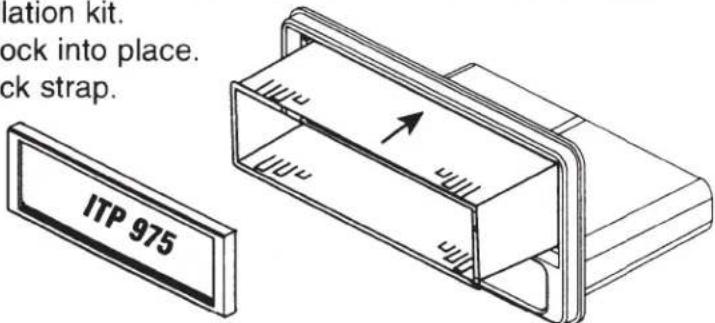
Optional use Trim Ring (ITP-975) may be used on some radios if desired.
Your new radio must have a trim ring around the face of the radio that is designed to be easily removed. Consult your radio owner's manual.
ISO MOUNT INSTRUCTIONS
Consult your page for specific ISO Mount assembly
Note: Some radio faces are larger in size than the ITP-975 Trim Ring allows. You may need to file the opening larger for some radios.
ISO Mount is necessary when the DIN sleeve is not available.
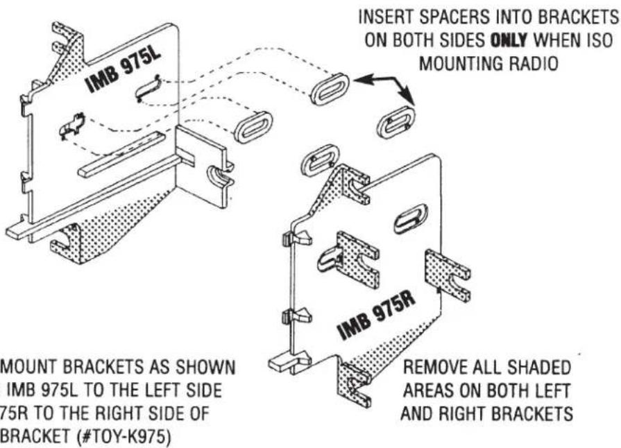
- Attach ISO mount brackets to rear of kit as shown in your illustration and attach to rear of pocket using small screws provided with kit.
- Insert ISO mountable radio between ISO mount brackets and loosely attach to sides of radio using screws provided with radio when possible or large wafer head screws supplied with kit. (Be sure the length of the screws DO NOT touch any electrical parts inside radio, some screws may need to be shortened.
- Attach ISO trim ring to face of kit.
- Slide radio forward or backward for desired look and tighten screws.
DASH DISASSEMBLY & RADIO REMOVAL INSTRUCTIONS
- Gently lift upward shift lever trim panel and slide back, disconnect harness and remove.
- Remove the (4) knobs from the A/C-heater controls.
- Remove the (2) Phillips screws below the A/C-heater controls.
- Remove the (2) Phillips screws securing the bottom edge of the climate controls to the subdash.
- Gently pry upward and towards you the radio trim panel/climate control trim bezel and remove.
- Remove the (4) 10mm bolts securing the radio.
- Slide the radio forward, disconnect the wire harnesses and antenna lead and remove the radio.
BRACKET PREPARATION
FOR DIN MOUNT APPLICATIONS

FOR ISO MOUNT APPLICATIONS

DASH DISASSEMBLY & RADIO REMOVAL INSTRUCTIONS
- Remove the (2) outer A/C-heater control knobs.
- Remove the (2) Phillips screws from these locations.
- Gently unsnap the A/C-heater control panel, disconnect the harnesses and remove.
- Gently unsnap the trim from around the radio and remove.
- Depress the tabs securing the heater controls in place and pull slightly forward and upward to allow access to the top radio mounting screws.
- Remove the (4) Phillips screws securing the radio.
- Gently slide the radio forward and disconnect the wire harnesses and antenna lead and remove the radio.
BRACKET PREPARATION
FOR DIN MOUNT APPLICATIONS

FOR ISO MOUNT APPLICATIONS
DASH DISASSEMBLY & RADIO REMOVAL INSTRUCTIONS
- Gently remove the screw cover caps from the lower sides of the radio mounting rails.
- Remove the (2) phillips screws from the base of each side of the main radio support bracket covers, and remove the covers.
- Remove the (4) phillips screws securing the radio to the sub-dash.
- Remove the (4) screws securing the Drink Tray/Ashtray assembly, and lower the assembly out of the way.
- Gently pull the radio forward.
- Disconnect the harness and antenna lead from the radio and remove the radio.
BRACKET PREPARATION
FOR DIN AND ISO MOUNT APPLICATIONS
REMOVE SHADED MOUNTING
BRACKETS FOR MR2 APPLICATION
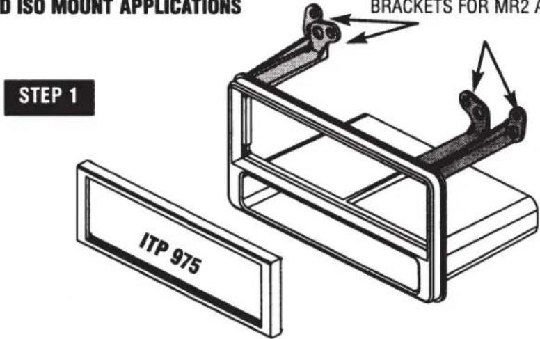
ATTACH BRACKETS TO REAR OF POCKET USING SCREWS SUPPLIED
INSERT SPACERS INTO BRACKETS ON BOTH SIDES ONLY WHEN ISO MOUNTING RADIO

DASH DISASSEMBLY & RADIO REMOVAL INSTRUCTIONS
- Open the center pocket below the climate controls and remove the (1) 10 mm bolt.
- Carefully Unclip the center console section with ashtray trim, disconnect the harness and remove console section.
- Carefully lift the center console side covering and remove.
- Remove the (2) lower 10 mm bolts from the bottom of driver side under dash panel.
- Carefully pull drivers side under dash panel outward and lay out of the way.
- Remove the (1) 10mm bolt at the lower edge of the radio trim bezel on the driver side.
- Unclip the trim from the front of the center console pocket.
- Carefully pry outward the climate control pod, disconnect the wire harness and remove pod.
- Remove the (2) 10mm bolts from behind the climate control location.
- Carefully unclip the entire radio/climate control trim bezel, disconnect all harnesses from bezel and remove.
- Remove the (2) 10mm bolts securing the factory radio to the sub-dash.
- Carefully pull radio forward, disconnect all harnesses and antenna leads and remove radio.
KIT ASSEMBLY
DIN MOUNT INSTRUCTIONS
- Insert DIN sleeve from your new radio into the radio opening of the installation kit.
- Depress the tabs from inside the sleeves opening upward, outward, and downward to secure the sleeve to the installation kit.
FOR DIN & ISO MOUNT APPLICATIONS
REMOVE SHADED MOUNTING TABS
FOR 4-RUNNER APPLICATION

- Remove the (4) chrome allen bolts securing the radio trim bezel.
- Gently unsnap the radio trim bezel and remove.
- Remove the (4) 10mm bolts securing the radio to the sub-dash.
- Gently pull the radio forward.
- Disconnect the harness and antenna lead from the radio and remove the radio
BRACKET PREPARATION
FOR DIN AND ISO MOUNT APPLICATIONS
DASH DISASSEMBLY & RADIO REMOVAL INSTRUCTIONS
- Starting from the bottom of the Radio trim bezel, carefully pry outward on the dash trim bezel to unclip the lower edge and sides.
- Angle the dash trim bezel outward from the bottom and pull the top of the panel down to unfasten the two upper tabs.
- Pull the trim bezel forward and disconnect all harnesses attached to the panel and remove panel.
- Remove the harness clamp attached at the rear of the left factory radio bracket.
- Remove the (4) 10mm bolts securing the factory radio to the sub-dash.
- Pull radio forward, disconnect the wire harness and antenna lead and remove radio.
BRACKET PREPARATION
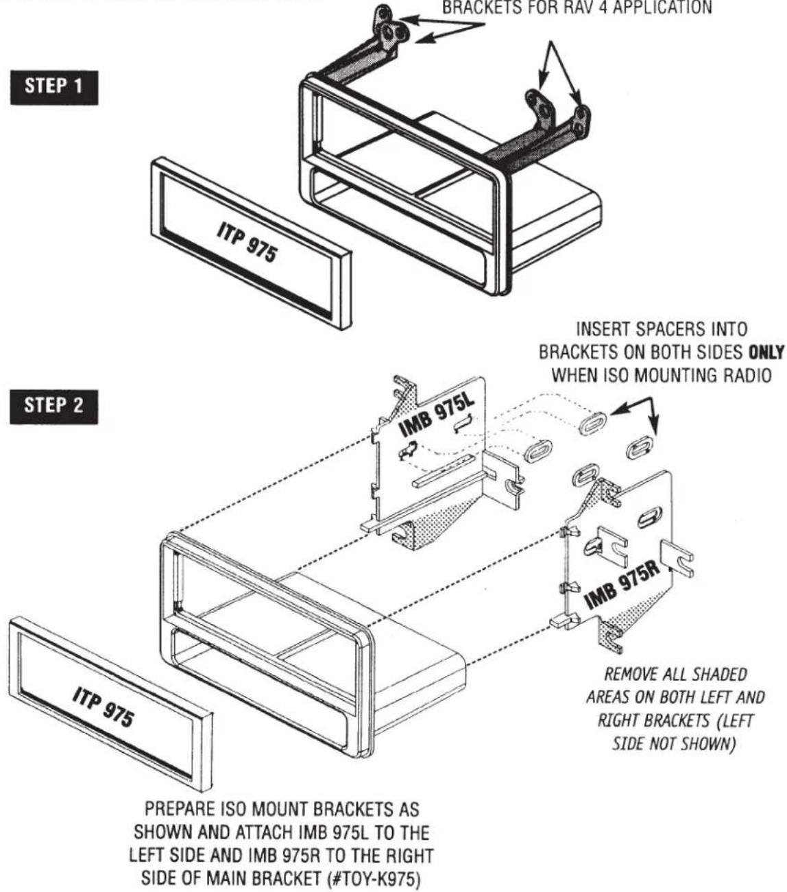
STEP 1
REMOVE SHADED
MOUNTING BRACKETS FOR
MATRIX APPLICATION
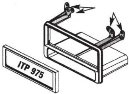
DIN MOUNT INSTRUCTIONS
- Insert DIN sleeve from your new radio into the radio opening of the installation kit.
- Depress the tabs from inside the sleeves opening upward, outward, and downward to secure the sleeve to the installation kit.
ISO MOUNT BRACKET PREPARATION
INSERT SPACERS INTO BRACKETS
ON BOTH SIDES ONLY WHEN ISO
MOUNTING RADIO
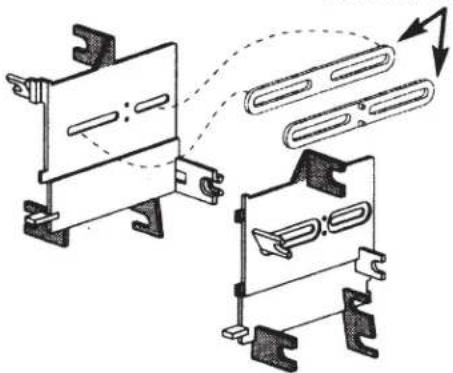
PREPARE ISO MOUNT BRACKETS AS SHOWN AND ATTACH IMB 975L TO THE LEFT SIDE AND IMB 975R TO THE RIGHT SIDE OF MAIN BRACKET (#TOY-K975)
STEP 2
ATTACH BRACKETS TO REAR OF POCKET USING SCREWS SUPPLIED

REMOVE ALL SHADED AREAS ON BOTH LEFT AND RIGHT BRACKETS (LEFT SIDE NOT SHOWN)
2001-07 TOYOTA HIGHLANDER
DASH DISASSEMBLY & RADIO REMOVAL INSTRUCTIONS
- Starting from the bottom carefully unsnap and remove trim bezel from around climate controls and radio.
- Remove (6) 10mm bolts securing entire climate controls / radio to sub-dash.
- Pull the entire assembly forward, disconnect all harnesses and antenna lead, and remove assembly.
- Remove the (8) phillips screws securing factory radio to assembly brackets and remove factory radio.
BRACKET PREPARATION
DIN MOUNT ONLY (see page 1)
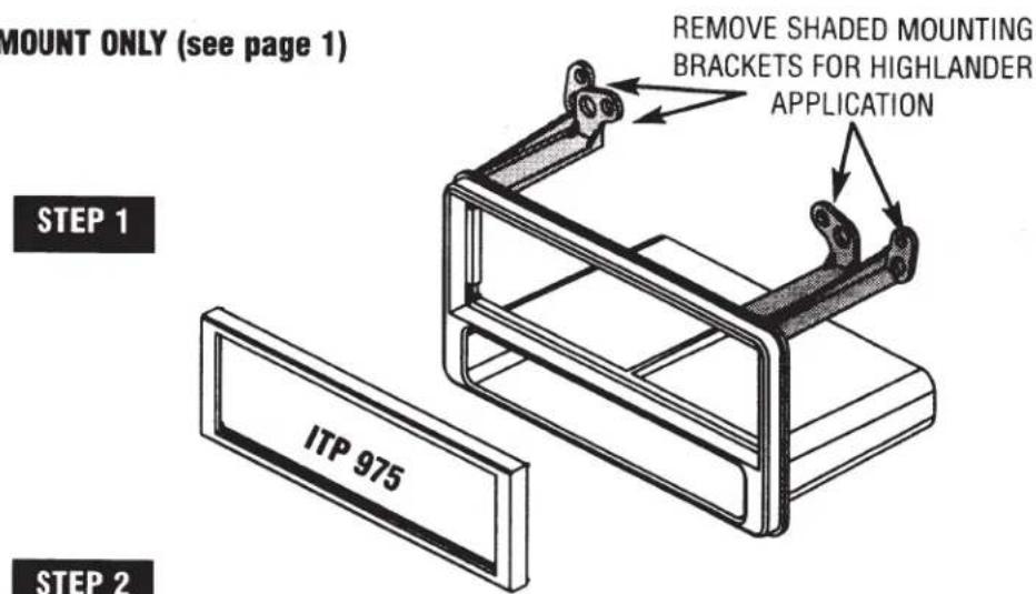
ATTACH LEFT AND RIGHT HIGHLANDER BRACKETS HMB-975 R AND HMB-975 L TO THE MAIN BRACKET AS SHOWN IN ILLUSTRATION B. THEN SECURE SIDE BRACKETS TO THE BACK OF THE POCKET USING 2 SMALL SCREWS PROVIDED WITH KIT.

KIT AND RADIO INSTALLATION INSTRUCTIONS
STEP 3
For information about other American International automotive accessories visit our website at:
http://www.americaninternational.net

American International
Automotive Products Division
1040 Avenida Acaso • Camarillo, CA 93012, U.S.A.
USA Sales (800) 336-6500
Canada Sales (888) 922-3006 • USA Fax (805) 388-7950
CUSTOMER HELP LINE
USA 800-323-4329 • Canada 800-245-8777
- VEHICLE APPLICATIONS
- TOYOTA
- SCION
- READ THIS PAGE AND YOUR VEHICLE PAGE BEFORE ATTEMPTING TO ASSEMBLE KIT
- DIN MOUNT INSTRUCTIONS
- ISO MOUNT INSTRUCTIONS
- CONSULT YOUR PAGE FOR SPECIFIC ISO MOUNT ASSEMBLY
- DASH DISASSEMBLY & RADIO REMOVAL INSTRUCTIONS
- BRACKET PREPARATION
- FOR DIN MOUNT APPLICATIONS
- FOR ISO MOUNT APPLICATIONS
- KIT ASSEMBLY
- FOR DIN & ISO MOUNT APPLICATIONS
- 2001-07 TOYOTA HIGHLANDER
- KIT AND RADIO INSTALLATION INSTRUCTIONS
- STEP 3
- AMERICAN INTERNATIONAL
Brand : American International
Model : TOYK975
Category : Mounting kit