RCI 6 - Electronic lock Dormakaba - Free user manual and instructions
Find the device manual for free RCI 6 Dormakaba in PDF.


| Type | Electronic Strike Lock |
| Brand | Dormakaba |
| Model | RCI 6 (L65 Low Profile / S65 Standard) |
| Power Input | 12VDC / 12-24VAC or 24VDC |
| Voltage Options | 12V or 24V |
| Latch Projection (Low Profile) | 1/2" or 5/8" |
| Latch Projection (Standard) | 3/4" |
| UL 294 Access Control Line Security | Level I |
| UL 294 Destructive Attack | Level I |
| UL 294 Endurance | Level IV |
| UL 294 Standby Power | Level I |
| Fail Mode | Selectable (Fail Safe or Fail Secure) |
| Frame Compatibility | Aluminum, Wood, Hollow Metal |
| Insert Depth (Standard) | 1-3/16" |
| Insert Depth (Low Profile) | 1-1/16" |
| Faceplate Options | B604, B605, B607, B608, B614 |
| Monitor Switches | Latch Monitor and Keeper Monitor (optional) |
| Mounting Tab Kit | Included for frames without tabs |
| Compliance | BHMA A156.31 |
| Weight (Approx.) | 1.5 lbs |
| Material | Zinc plated steel |
Frequently Asked Questions - RCI 6 Dormakaba
User questions about RCI 6 Dormakaba
0 question about this device. Answer the ones you know or ask your own.
Ask a new question about this device
Download the instructions for your Electronic lock in PDF format for free! Find your manual RCI 6 - Dormakaba and take your electronic device back in hand. On this page are published all the documents necessary for the use of your device. RCI 6 by Dormakaba.
USER MANUAL RCI 6 Dormakaba
The RCI L65 Low Profile version accepts 1/2" or 5/8" latch projection (perfect for narrow stile aluminum frames). The RCI S65 Standard version is ideal when you require 3/4" latch projection.
-
Determine the vertical centerline of the door lock face and the horizontal centerline of the latch.
IMPORTANT: When determining the horizontal centerline observe the following:
FOR MORTISE LOCKS: Align the angled ramps of the lip bracket with the deadlock trigger of the mortise latch. FOR CYLINDRICAL LOCKS: Align the center of the latch with the center of the strike opening.** -
Transfer both the horizontal and vertical centerlines to the doorframe.**
-
Prepare the doorframe for cutting as shown in the appropriate drawing.
RCI S6504 Aluminum Frames, 1-3/16" Insert Depth Modular AS65 with B604 faceplate

other
| Category | Measurement | FRACTIONAL INCHES (mm) | DECIMAL INCHES (mm) | METRIC mm | |---|---|---|---|---| | A | 1-1/4 | 1.250 | 31.75 | | | B | 4-7/8 | 4.875 | 123.83 | | | C | 3-3/8 | 3.375 | 85.73 | | | D | 1-3/16 | 1.188 | 30.16 | | | E | 3/8 | .375 | 9.53 | | | F | 1/8* .125* | 3.18* | | | | G | 1-11/16 | 1.688 | 42.86 | | | X | Vertical Centerline of Door** | | | | | R | 5/32 | 0.156 | 3.97 | | | K | 4-1/8 | 4.125 | 104.78 | | | M | 12-24 | — | — | | The image contains a schematic representation of a door structure with dimension labels and a 3D model of the door.| UL 294 Performance Ratings: |
| Access Control Line Security : Level I |
| Destructive Attack : Level I |
| Endurance : Level IV |
| Standby Power : Level I |
-
If required, install the 'no weld' mounting brackets per page 4.
-
Attach the strike faceplate to the lip bracket with the self-tapping screws provided. (It may be desirable to leave these screws slightly loose to facilitate insertion into the doorframe.
-
Connect the incoming wiring from the power supply (see wiring instructions).
-
Install the door strike in the doorframe using the screws provided.
RCI L6504 Aluminum Frames, 1-1/16" Insert Depth Modular AL65 with B604 faceplate

NOTE: Specifications subject to change without notice.
* Dimension F is measured from face of mounting tab to face of frame.
** Dimension X on the drawing is determined by the vertical centerline of the door. If the latch incorporates a deadlocking pin additional steps will be necessary to ensure proper operation of the deadlocking pin. Measure the thickness of the deadlocking pin and add this thickness to Dimension X to relocate the vertical centerline an appropriate distance on the frame.
NOTE: Specifications subject to change without notice. * Dimension F is measured from face of mounting tab to face of frame. ** Dimension X on the drawing is determined by the vertical centerline of the door. If the latch incorporates a deadlocking pin additional steps will be necessary to ensure proper operation of the deadlocking pin. Measure the thickness of the deadlocking pin and add this thickness to Dimension X to relocate the vertical centerline an appropriate distance on the frame.
RCI S6505 Aluminum & Wood Frames, 1-3/16" Insert Depth Modular AS65 with B605 faceplate
| MEASUREMENT | FRACTIONAL INCHES | DECIMAL INCHES | METRIC mm |
| A | 1-1/8 | 1.125 | 28.58 |
| B | 5-7/8 | 5.875 | 149.23 |
| C | 3-3/8 | 3.375 | 85.73 |
| D | 1-3/16 | 1.188 | 30.16 |
| E | 1/4 | 0.250 | 6.35 |
| F | 1/8* | .125* | 3.18* |
| G | 1-11/16 | 1.688 | 42.86 |
| X | Vertical Centerline of Door** | ||
| R | 5/32 | .156 | 3.97 |
| K | 5-3/8 | 5.375 | 136.53 |
| M | 12-241 | — | — |

RCI L6505 Aluminum & Wood Frames, 1-1/16" Insert Depth Modular AL65 with B605 faceplate
| MEASUREMENT | FRACTIONAL INCHES | DECIMAL INCHES | METRIC mm |
| A | 1-1/8 | 1.125 | 28.58 |
| B | 5-7/8 | 5.875 | 149.23 |
| C | 3-3/8 | 3.375 | 85.78 |
| D | 1-3/32 | 1.094 | 27.78 |
| E | 1/4 | 0.250 | 6.35 |
| F | 1/8* | .125* | 3.18* |
| G | 1-11/16 | 1.688 | 42.86 |
| X | Vertical Centerline of Door** | ||
| R | 5/32 | .156 | 3.97 |
| K | 5-3/8 | 5.375 | 136.53 |
| M | 12-241 | — | — |

RCI S6507 Aluminum & Wood Frames, 1-3/16" Insert Depth Modular AS65 with B607 faceplate
| MEASUREMENT | FRACTIONAL INCHES | DECIMAL INCHES | METRIC mm |
| A | 1-1/4 | 1.250 | 31.75 |
| B | 6-7/8 6. | 375 174 | 63 |
| C | 3-3/8 | 3.375 | 85.7 |
| D | 1-3/16 | 1.188 | 30.16 |
| E | 3/8 | 0.375 | 9.53 |
| F | 1/8* .125* | 3.18* | |
| G | 1-11/16 | 1.688 | 42.86 |
| X | Vertical Centerline of Door** | ||
| R | 5/32 | .156 | 3.97 |
| K | 6-1/8 | 6.125 | 155.58 |
| M | 12-24' | — | — |
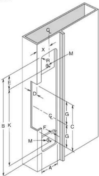
RCI L6507 Aluminum & Wood Frames, 1-1/16" Insert Depth Modular AL65 with B607 faceplate
| MEASUREMENT | FRACTIONAL INCHES | DECIMAL INCHES | METRIC mm |
| A | 1-1/4 | 1.250 | 31.75 |
| B | 6-7/8 6. | 875 174 | 63 |
| C | 3-3/8 | 3.375 | 85.7 |
| D | 1-3/32 | 1.094 | 27.78 |
| E | 3/8 | 0.375 | 9.53 |
| F | 1/8* .125* | 3.18* | |
| G | 1-11/16 | 1.688 | 42.86 |
| X | Vertical Centerline of Door** | ||
| R | 5/32 | .156 | 3.97 |
| K | 6-1/8 | 6.125 | 155.58 |
| M | 12-24† | — | — |

NOTE: Specifications subject to change without notice.
* Dimension F is measured from face of mounting tab to face of frame.
** Dimension X on the drawing is determined by the vertical centerline of the door. If the latch incorporates a deadlocking pin additional steps will be necessary to ensure proper operation of the deadlocking pin. Measure the thickness of the deadlocking pin and add this thickness to Dimension X to relocate the vertical centerline an appropriate distance on the frame.
For wood frame door installations, substitute #12 wood screws for dimension M.
RCI S6508 Aluminum & Wood Frames, 1-3/16" Insert Depth Modular AS65 with B608 faceplate
RCI L6508 Aluminum & Wood Frames, 1-1/16" Insert Depth Modular AL65 with B608 faceplate
| MEASUREMENT | FRACTIONAL INCHES | DECIMAL INCHES | METRIC mm |
| A | 1-7/16 | 1.438 | 36.51 |
| B | 7-15/16 | 7.938 | 201.61 |
| C | 3-3/8 | 3.375 | 85.73 |
| D | 1-3/16 | 1.188 | 30.16 |
| E | 1/4 | 0.250 | 6.35 |
| F | 1/8* .125* | 3.18* | |
| G | 1-11/16 | 1.688 | 42.86 |
| X | Vertical Centerline of Door** | ||
| R | 5/32 | .156 | 3.97 |
| K | 7-7/16 | 7.438 | 188.91 |
| M | 12-24' | — | — |

| MEASUREMENT | FRACTIONAL INCHES | DECIMAL INCHES | METRIC mm |
| A | 1-7/16 | 1.438 | 36.51 |
| B | 7-15/16 | 7.938 | 201.61 |
| C | 3-3/8 | 3.375 | 85.73 |
| D | 1-3/32 | 1.094 | 27.78 |
| E | 1/4 | 0.250 | 6.35 |
| F | 1/8*.125* | 3.18* | |
| G | 1-11/16 | 1.688 | 42.86 |
| X | Vertical Centerline of Door** | ||
| R | 5/32 | .156 | 3.97 |
| K | 7-7/16 | 7.438 | 188.91 |
| M | 12-241 | — | — |
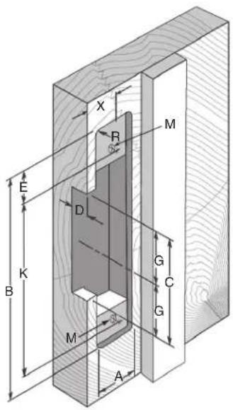
RCI S6514 Hollow Metal Frames, 1-3/16" Insert Depth Modular AS65 with B614 faceplate
| MEASUREMENT | FRACTIONAL INCHES | DECIMAL INCHES | METRIC mm |
| A | 1-1/4 | 1.250 | 31.75 |
| B | 4-7/8 | 4.875 | 123.83 |
| C | 3-3/8 | 3.375 | 85.73 |
| D | 1-3/16 | 1.188 | 30.16 |
| E | 3/8 | .375 | 9.53 |
| F | 1/8* .125* | 3.18* | |
| G | 1-11/16 | 1.688 | 42.86 |
| X | Vertical Centerline of Door** | ||
| K | 4-1/8 | 4.125 | 104.78 |
| M | 12-24 | — | — |
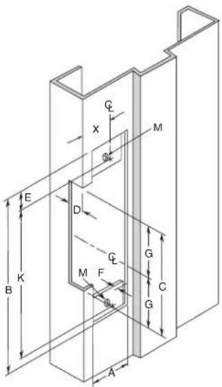
RCI L6514 Hollow Metal Frames, 1-1/16" Insert Depth Modular AL65 with B614 faceplate
| MEASUREMENT | FRACTIONAL INCHES | DECIMAL INCHES | METRIC mm |
| A | 1-1/4 | 1.250 | 31.75 |
| B | 4-7/8 | 4.875 | 123.83 |
| C | 3-3/8 | 3.375 | 85.73 |
| D | 1-3/32 | 1.094 | 27.78 |
| E | 3/8 | .375 | 9.53 |
| F | 1/8* .125* | 3.18* | |
| G | 1-11/16 | 1.688 | 42.86 |
| X | Vertical Centerline of Door** | ||
| K | 4-1/8 | 4.125 | 104.78 |
| M | 12-24 | — | — |

NOTE: Specifications subject to change without notice.
* Dimension F is measured from face of mounting tab to face of frame.
** Dimension X on the drawing is determined by the vertical centerline of the door. If the latch incorporates a deadlocking pin additional steps will be necessary to ensure proper operation of the deadlocking pin. Measure the thickness of the deadlocking pin and add this thickness to Dimension X to relocate the vertical centerline an appropriate distance on the frame.
For wood frame door installations, substitute #12 wood screws for dimension M.

natural_image
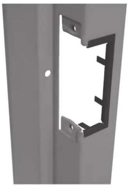
Metal bracket with cutouts and mounting holes, no text or symbols visibleMounting Tab Kit Instructions
Mounting tab kit is for use with aluminum and steel frames that do not have factory installed mounting tabs for electric strike installation.
- Prepare the frame as shown in the approximate drawing. Fasten the mounting tab to the faceplate of the strike, selecting the appropriate shims for the installation.
- Using the assembled strike and tabs as a template, place against the frame and mark the mounting hole locations. Remove and drill a 3/16" hole in frame for each mounting tab and countersink the frame.
- Remove the tabs from the faceplate and install in the frame using the 12-24 x 3/8" machine screws supplied. Tabs are zinc plated and drilled and tapped for this purpose.
- Make final electrical connections per wiring instructions and mount strike to the tabs with the 12-24 x 3/8" machine screws.
Trim Plate Instructions
- Position the Trim Plate on the frame cut-out to verify fit and coverage.
- Adjust cut-out if required.
- Bend the four tabs to hold the Trim Plate onto the frame.
- For a tighter fit, pre-bend the two long flange tabs before sliding onto the frame where space allows.
- Secure the strike to the frame as per strike installation instructions.
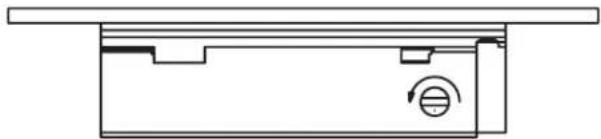
Fail Safe
Rotate the adjustment screw so the dimple is fully rotated to opposite the faceplate side of the strike (fully counter clockwise). Your strike is now fail safe and requires power to lock. See Fig. 1.
natural_image
Pure technical diagram of a mechanical component with no text or symbolsFig. 1 Fail Safe = screw fully counter clockwise
Fail Secure
Rotate the adjustment screw so the dimple is fully rotated to the faceplate side of the strike (fully clockwise). Your strike is now fail secure and requires power to unlock the door. See Fig 2.

natural_image
Pure technical diagram of a mechanical component with no text or symbolsFig. 2 Fail Secure = screw fully clockwise
Lip Bracket Adjustment
If your door or latch is out of adjustment, the insert can be adjusted forward or back as required for proper alignment to the latch. See Fig. 3
- Remove the strike from the frame.
- Remove the faceplate from the strike.
- 2 screws secure the lip bracket to the main insert.
- Loosen these screws approximately 1-1/2 to 2 full turns to allow the insert to move forward or backward as required.
- Once the adjustment is made tighten all screws and reinstall the strike in the frame.
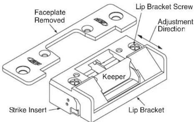
Fig. 3 Lip bracket adjustment
Wiring Instructions
NOTE: Overheated or Burnt Coils caused by incorrect input voltage / wire harness combinations will not be covered under warranty.
For 12VDC or 12-24VAC input power :
- connect RED and BLUE wires to positive (+)
- connect BLACK and YELLOW wires to negative (-)
For 24VDC input power only :
- connect YELLOW and BLUE wires together
- connect RED wire to positive (+)
- connect BLACK wire to negative (-)
If using AC power, polarity is not observed.
To meet BHMA A156.31 install the MOV provided across the positive and negative wires or terminals of the harness. The MOV is not polarity sensitive.
NOTE: If a suppression diode is required for access control, observe proper polarity.
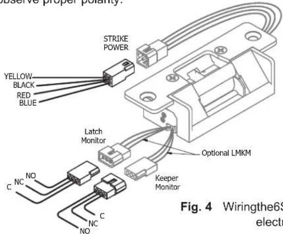
Fig. 4 Wiringthe6Series electric strike
Latch Monitor Wires\*
Black = Common (C)
Blue = Normally Close (NC)
Orange = Normally Open (NO)
Keeper Monitor Wires\*
Black = Common (C)
Yellow = Normally Closed (NC)
Green = Normally Open (NO)
*Latch Monitor and Keeper Monitor Switch Ratings: 24VDC (SPDT), 2 Amp, resistive load
When using LMKM option:
If the lockset on the door has a 1/2" or 5/8" latch projection, the RCI L65 model is appropriate. If the lockset on the door has a 3/4" latch projection, you must use the RCI S65 model.
NOTE: Contacts are indicated with the keeper in a closed and locked condition, with no latch present.
SolutionPossible CausesProblem
| 1. Strike will not lock or unlock properly | No power to the insert Using a multimeter, confirm that you have the correct output voltage at the power supply.Using a multimeter, confirm that you have the correct input voltage at the strike.Confirm that all connections are tight and secure. | |
| Incorrect voltage used Confirm that the insert and power supply are the proper voltage.Strike is binding Confirm that the strike keeper functions when the door is open. If the strike operates correctly, adjust door or strike to eliminate any backpressure.Confirm that the strike cavity depth is compatible with the lock set. | ||
| 2. Strike releases but won't buzz | Improper power supply Replace the power supply with a correct voltage AC power supply, and the 12V connector. If this cannot be done, a DC piezo buzzer can be installed. | |
| 3. Strike makes a buzzing sound | Improper power supply Replace the power supply with a correct voltage DC power supply.Improper application A strike connected to an AC power supply will buzz unless a rectifier is installed. | |
| 4. Insert has a burnt smell | Improper voltage Confirm that you have the correct output voltage at the power supply.Improper installation Confirm that the correct connector was used when installing the strike 12V for 12VDC & 12-24VAC, 24V for 24VDC only.Confirm that all connections are tight and secure. | |
| 5. Mortise lock not dead latching | Improper Installation Check alignment of dead latch and lip bracket ramp.Door has sagged Adjust door alignment. | |
| 6. Cylindrical deadlatching not working | Improper Installation / Door has warped | Adjust the strike horizontal adjustment. (See Installation Instructions). |
| 7. Door won't latch Door has warped or sagged creating excessive back pressure | Re-align door in frame or replace. | |
| 8. Monitor switch is not functioning | Short in wiring Confirm that all connections are tight and secure.Using a multimeter confirm continuity of the N/O & N/C sides of the switch.Latch or keeper are not functioning properly | Confirm that the keeper is closing properly and that the lever in the strike cavity is operating freely. |
Brand : Dormakaba
Model : RCI 6
Category : Electronic lock