RCI 8380 - Electronic lock Dormakaba - Free user manual and instructions
Find the device manual for free RCI 8380 Dormakaba in PDF.


| Product Type | Electronic Lock |
| Brand | Dormakaba |
| Model | RCI 8380 |
| Dimensions (Mortise) | 4.0 x 2.75 x 1.0 in (102 x 70 x 25 mm) |
| Weight | 2.0 lbs (0.9 kg) |
| Power Supply | 4 x AA batteries (6V DC) or 9V battery backup |
| Battery Life | Up to 1 year under normal use |
| Low Battery Warning | Audible beeps and LED indicator |
| Access Methods | Keypad PIN (up to 100 user codes), RFID card, mechanical key override |
| PIN Length | 4 to 8 digits |
| RFID Standard | 13.56 MHz / ISO 14443A (MIFARE compatible) |
| Mechanical Override | Standard mortise cylinder (Schlage C keyway) |
| Security Grade | ANSI/BHMA Grade 1 (Commercial) |
| Locking Mechanism | Motor-driven deadbolt, 3/4") |
| Backset | Adjustable 2-3/8" or 2-3/4" (60 or 70 mm) |
| Door Thickness Range | 1-3/8" to 2" (35 to 51 mm) |
| Operating Temperature | -4°F to 140°F (-20°C to 60°C) |
| Weather Resistance | IP54 (indoor/covered outdoor use) |
| Finish Options | Matte Black, Satin Nickel, Bright Chrome |
| Installation | Standard mortise prep, includes mounting hardware |
| Included Parts | Lock body, exterior keypad, interior escutcheon, strike plate, screws, batteries, RFID cards (2) |
| Maintenance | Clean with a soft dry cloth; avoid solvents |
| Certifications | UL 294, FCC Part 15, ADA compliant |
| Warranty | 2-year limited manufacturer warranty |
Frequently Asked Questions - RCI 8380 Dormakaba
User questions about RCI 8380 Dormakaba
0 question about this device. Answer the ones you know or ask your own.
Ask a new question about this device
Download the instructions for your Electronic lock in PDF format for free! Find your manual RCI 8380 - Dormakaba and take your electronic device back in hand. On this page are published all the documents necessary for the use of your device. RCI 8380 by Dormakaba.
USER MANUAL RCI 8380 Dormakaba
Pre-Installation Instructions
- This product must be installed according to all applicable building and life safety codes.
- Due to the variety of mounting configurations available with this product, a survey and assessment of the physical area in which the product will be installed must be performed.
- The door frame must be inspected and deemed structurally sound prior to installation of the electromagnetic lock. The structural integrity of the mounting surfaces must be strong enough to meet or exceed the holding force of the product.
- The product must be protected from potential damage due to intruders or tampering.
- The product should be installed in a location that will not hinder or create a potential safety hazard to authorized personnel accessing the protected area.
- Because electromagnetic locks are used in a variety of applications and different door frame configurations, an experienced installer with knowledge of this product must make a determination of the optimal mounting method for this specific application.
PLEASE DELIVER ALL INSTALLATION INSTRUCTIONS TO THE END-USER UPON COMPLETION OF THE INSTALLATION.
- The components, hardware, installation instructions and mounting template included with this product are intended for use on swinging and sliding gates.
- Do not use as a doorstop. This will void warranty.
- Separate accessories not included with this product may be used in the following applications:
• Inswinging doors and gates
• Sliding gates and doors
Refer to the Template for further information. Accessories may impact holding force.
- Installation of this product should be done by an experienced installer with knowledge of this product.
NOTE: It is highly recommended that thread locking compound be applied to all screws during installation to reduce chance of screws loosening over extended time.
Instructions
- Please read template mounting instructions and use template provided for installing the electromagnetic lock.
NOTE: During installation of the armature plate to the door it is essential that the armature plate remains movable. The armature plate must be allowed to pivot on the center-mounting bolt to allow proper alignment with the magnet surface. If the plate is not aligned with the magnet surface, the lock may lose holding force or not lock at all.
The head of the armature mounting bolt ships with a rubber washer affixed to it. This washer should project slightly beyond the surface of the armature plate. This is to allow the washer to expand when power is removed and break the air vacuum between the plate and the magnet surface. If this washer is removed or trimmed the lock will appear to have some holding force even when power is removed.
For added safety, thread locking compound has been provided for the armature plate bolt and the four electromagnetic lock mounting screws.
WARNING: Improper installation, maintenance, inspection or usage of the product or any related accessories or parts may cause the electromagnetic lock, armature plate and associated hardware to disengage and fall, causing serious bodily injury and property damage. Rutherford Controls Int'l Inc. and/or Rutherford Controls Int'l Corp. will not be liable to the installer, purchaser, end user or anyone else for damage or injury to person or property due to improper installation, care, storage, handling, maintenance, inspection, abuse, misuse or act of God or nature involving this product or any related accessories or parts.
-
Connecting wire should be of sufficient gauge to prevent line loss.
-
The 8380 electromagnetic lock requires a filtered, regulated DC power source for optimal performance.
8380 Electromagnetic Lock Installation Instructions (Continued)
Wiring Instructions
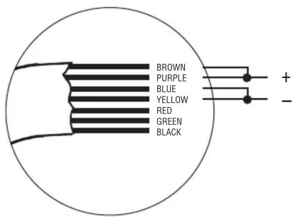
WARNING – Misconnection of the wires will cause the MOV inside the electromagnetic lock to fail. This will NOT be covered under warranty.
12 VDC INPUT
Twist brown and purple wires together and connect to positive side of power source. Twist blue and yellow wires together and connect to negative side of power source.

24 VDC INPUT
Twist purple and blue wires together; then connect brown wire to positive side of power source and yellow wire to negative side of power source.
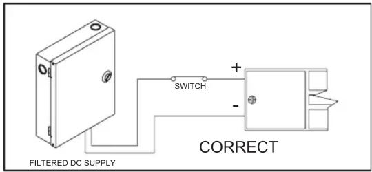
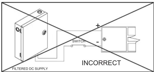
Fig. 2 – Power Connections
To Ensure Instant Release All switching devices must be wired in between the DC power source and the positive terminal of the lock in Fig 2.
Switching the negative power supply line will not allow the lock to release immediately. RCI electromagnetic locks contain MOV's for surge suppression and do not require any additional suppression to be added during installation. The installation of diodes across the lock input terminals will cause a delay in release.

Magnet Locked - When the magnet is locked, the common contact (black) and the normally open contact (green or white) are closed. The normally closed contact (red) would be open.
Magnet Unlocked - When the magnet is unlocked, the common contact (black) and the normally closed contact (red) are closed.
Reed switch is operational when the magnetic lock is powered and the door is in the closed position.
Reed switch contacts are rated 24VDC @ 0.2amps maximum.
PLEASE DELIVER ALL INSTALLATION INSTRUCTIONS TO THE END-USER UPON COMPLETION OF THE INSTALLATION.
8380 Electromagnetic Lock Installation Instructions (Continued)
Troubleshooting
| Problem Possible Cause Solution | ||
| Door will not lock(no magnetic attraction) | Absence of DC voltage at magnet terminals. | Check power supply and wiring. |
| Reduced holding force Inadequate contact between armature and face of magnet. | Ensure mating surfaces are clean and in proper alignment.Make sure to follow the armature plate mounting instructions on the template and Page 1 of this install. | |
| Delay in lock release Circuit not broken (open) between power supply and magnetic lock. | Ensure that switching devices are interrupting the DC power and not the AC power supply voltage. Ensure rubber washer on armature plate mounting bolt has not been removed or damaged.Check that switching device interrupts the positive wire and not the negative wire. (See Fig. 2) | |
| Secondary diode installed | ||
| RLS status incorrect | Misalignment of armature plate. | Check to see that alignment agrees with template. Reposition armature plate. Contact manufacturer. |
Power Input Requirements
| Voltage Current | |
| 12VDC 0.48A | |
| 24VDC 0.24A | |
NOTE: Specifications are subject to change without notice.
NOTE: All RCI electromagnetic locks must be powered with filtered and regulated DC power supplies such as the RCI 10 Series UL Listed power supply. RCI offers a full line of power supplies and switching devices that are suitable for use with the 8300 Series locks.

Inspection and Maintenance
This product and all related accessories or parts must be inspected and maintained on a quarterly basis. Contacting surfaces of the electromagnetic lock and armature plate must be kept free of contaminating materials. Surfaces must be cleaned periodically with a non-abrasive cleaner.
All mounting fasteners must be inspected on a quarterly basis. When properly installed, the ends of the armature plate allow a slight movement but the plate will feel secure when grasped at the bolt. There should be no movement to the mounting bracket or housing of the electromagnetic lock.
For added safety, thread locking compound has been provided for the armature plate bolt and the four captive electromagnetic lock mounting screws.
WARNING: Improper installation, maintenance, inspection or usage of the product or any related accessories or parts may cause the electromagnetic lock, armature plate and associated hardware to disengage and fall, causing serious bodily injury and property damage.
8380 Electromagnetic Lock Installation Instructions (Continued)
WIRE GAUGE SELECTIONS
| Total One-Way Length of Wire Run (ft.) | Load Current @ 24V1/4A 1/2A 3/4A 1A 1-1/4A 1-1/2A 2A 3A |
| 100242018 | 816161412 |
| 150221816 | 614141210 |
| 200201816 | 414121210 |
| 250181614 | 412121210 |
| 300181614 | 2121210- |
| 400181412 | 21010-- |
| 500161412 | 1010--- |
| 750141210 | 10---- |
| 1000141010 | ---- |
| 15001210 | ---- |
| Total One-Way Length of Wire Run (ft.) | Load Current @ 12V1/4A 1/2A 3/4A 1A 1-1/4A 1-1/2A 2A 3A |
| 1002018161 | 414121210 |
| 1501816141 | 2121210- |
| 2001614121 | 21010-- |
| 2501614121 | 01010-- |
| 3001612121 | 010--- |
| 400141210---- | |
| 500141010---- | |
| 7501210---- | |
| 100010---- | |
| 150010---- |
Wire Gauge Chart courtesy of Electronic Locking Devices by John L. Schum
Brand : Dormakaba
Model : RCI 8380
Category : Electronic lock