Oracode 480 - Electronic lock Dormakaba - Free user manual and instructions
Find the device manual for free Oracode 480 Dormakaba in PDF.


| Product Type | Electronic Lock |
| Brand | Dormakaba |
| Model | Oracode 480 |
| Category | Electronic Lock |
| Power Source | 3 AA alkaline batteries |
| Key Override | Yes, with mechanical key cylinder (may ship separately) |
| Backset | Adjustable: 2-3/8" (60mm) or 2-3/4" (70mm) |
| Door Thickness Compatibility | 1-3/8" to 2" (optional hardware kit for 2" to 2.5") |
| Wireless Communication | ZigBee via optional Smart Controller (Oracode 480i series) |
| Lock Handing | Field reversible (left/right hand) |
| Deadbolt Operation | Thumbturn (outside/inside) or code entry |
| Programming | Via Oracode Maintenance Unit and website (www.kaba-ecode.com) |
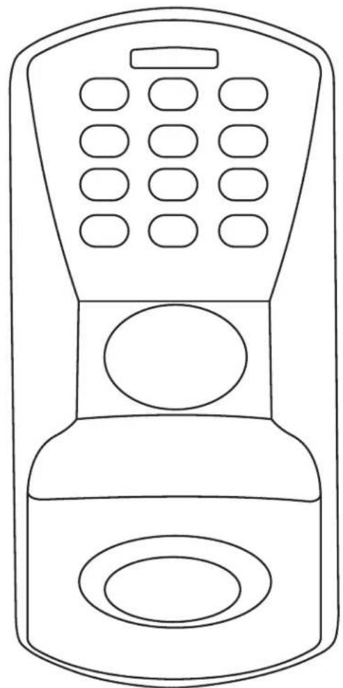
| Code Entry | Keypad with green/red LED and beep confirmation |
| Time Backup | Internal battery keeps time for min. 4 weeks when main batteries disconnected |
| Tools Required for Installation | Drill, hole saws (1", 2-1/8"), chisel, screwdrivers, safety glasses |
| Certifications (Smart Controller) | FCC ID: 2AIYWPLUS450, IC: 26382-PLUS450 |
| Warranty | Standard dormakaba warranty (excludes installation damage) |
| Usage Restriction | Not designed for emergency exit doors |
Frequently Asked Questions - Oracode 480 Dormakaba
User questions about Oracode 480 Dormakaba
0 question about this device. Answer the ones you know or ask your own.
Ask a new question about this device
Download the instructions for your Electronic lock in PDF format for free! Find your manual Oracode 480 - Dormakaba and take your electronic device back in hand. On this page are published all the documents necessary for the use of your device. Oracode 480 by Dormakaba.
USER MANUAL Oracode 480 Dormakaba
Installation Instructions

WARNING
- Please read and follow all directions carefully.
- This lock is not designed to be used on emergency exit doors.
- Carefully inspect glass, door frame, door etc. to ensure the recommended procedure will not cause damage. dormakaba standard warranty does not cover damages cause by installation.
- Wear safety glasses when making the holes.
- All the following operations and testing of the lock to be done with door open.
Tools Required
- Safety Glasses
• 1/2" (13mm) Chisel
• 1/8" (3mm) Drill Bit - 5/32" (4mm) Drill Bit
• 1" Drill Bit or Hole Saw
• 2 1/8" (54mm) Hole Saw - Drill
- Awl or Center Punch
- Screwdriver, 1/8" slotted
• Phillips Screwdriver (#2) - Adjustable Square
- Tape Measure
1A Install strike on wood frame

1B Install strike on steel frame

1C Door Preparation

A = Backset = 2 3/4" (70mm) or 2 3/8" (60mm)
- Determine which template fits your 480 lock installation, either 2 3/8" (60mm) or 2 3/4" (70mm) backset.
- Place appropriate template (supplied) onto door and mark holes.
- Drill holes as per dimensions on the template, the 1" (25mm) hole to be on the center line of door thickness.
- Mortise door edge for dead bolt face plate.
- Drill 2 1/8" from both sides of the door to prevent unsightly damage.
2 Adjust backset of deadbolt

The dead bolt is pre-set at 2 3/4" (70mm) backset. Proceed as illustrated to change to 2 3/8" (60mm) backset, if required.
3 Install dead bolt in door

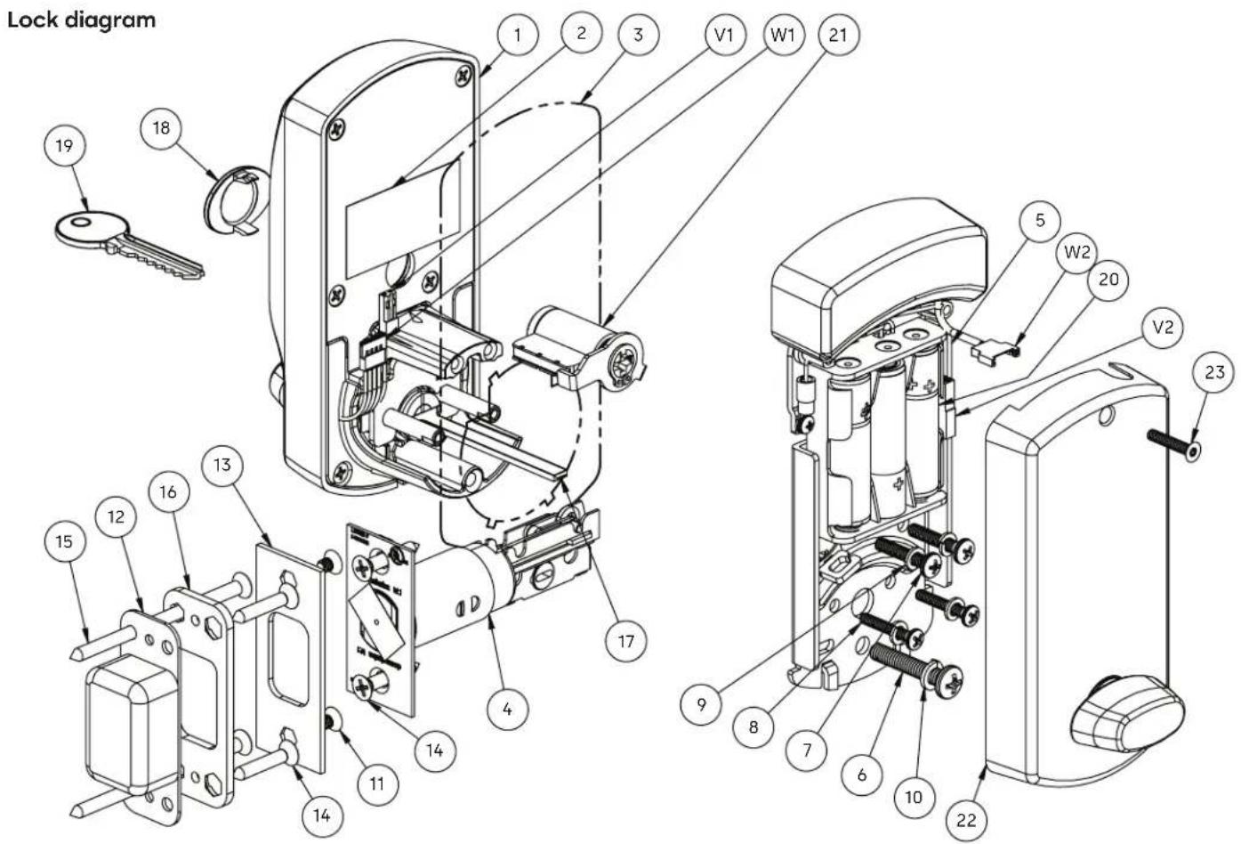
Parts list
- Outside Housing Assembly (1)
- Bar Code Label (1)
- Outside Housing Gasket (1)
- Dead Bolt (1)
- Inside Trim Assembly (1)
- Machine Screw, Pan Head, SS, PH #3, 12-24 (1)
- Machine Screw, Pan Head, ZP, PH #2, 8-32 (2)
- Machine Screw, Pan Head, ZP, PH #2, 6-32 (2)
- Split Lock Washer, No. 8, SS 18-8 (2)
- Split Lock Washer, No. 12, SS (1)
- Machine Screw, Flat Head, Brass, PH #2, 8-32 x 7/32" (2)
- Dust Box (1)
- Striker Plate (1)
- Wood Screw, PH #2, #8 x 1" (4)
- Wood Screw, PH #2, #8 x 3" (2)
- Reinforcing Plate (1)
- Tail Piece Door 1 3/8" to 2" (1)
- Cap (1)
- Override Key (May be shipped separately) (1)
- Battery Cell, AA Alkaline (3)
- Key Cylinder (May be shipped separately) (1)
- Inside Cover (1)
- Machine Screw, Flat Head, SS 304, PH #2, 6-32 x .750 (1)

When installing the lock, please carefully slide post through deadbolt holes
4 Key override cylinder
If cylinder is not already assembled in the lock, proceed as follow.

If required, re-tighten post while making sure not to pinch retaining ring. Keep retaining ring at 12 o'clock position.
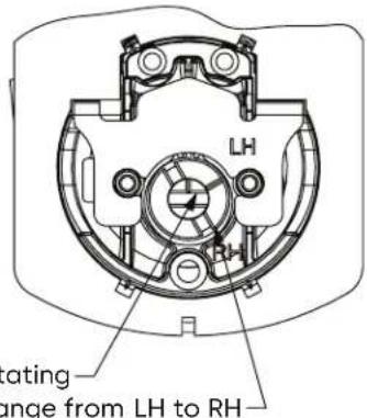
5 Adjust lock handing on outside housing assembly
Left hand (LH)
Right hand (RH)
1. Hold inner cam in place, groove always points to 12 o'clock.
2. Rotate outer cam counter clockwise until groove points to 6 o'clock


6 Assemble tail piece Remove inside cover
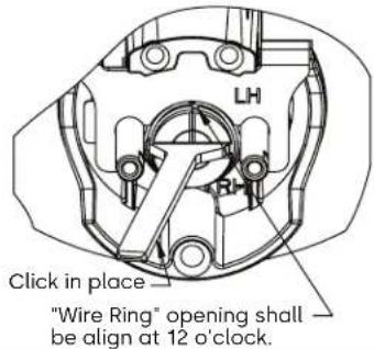

8 Assemble outside housing
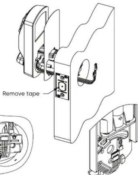
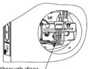
Run cable through door and under deadbolt
Run cable through inside trim 'back plate slot.

Make sure the power cable run inside cylindrical hub before mounting the lock on door panel.
9 Install inside trim assembly
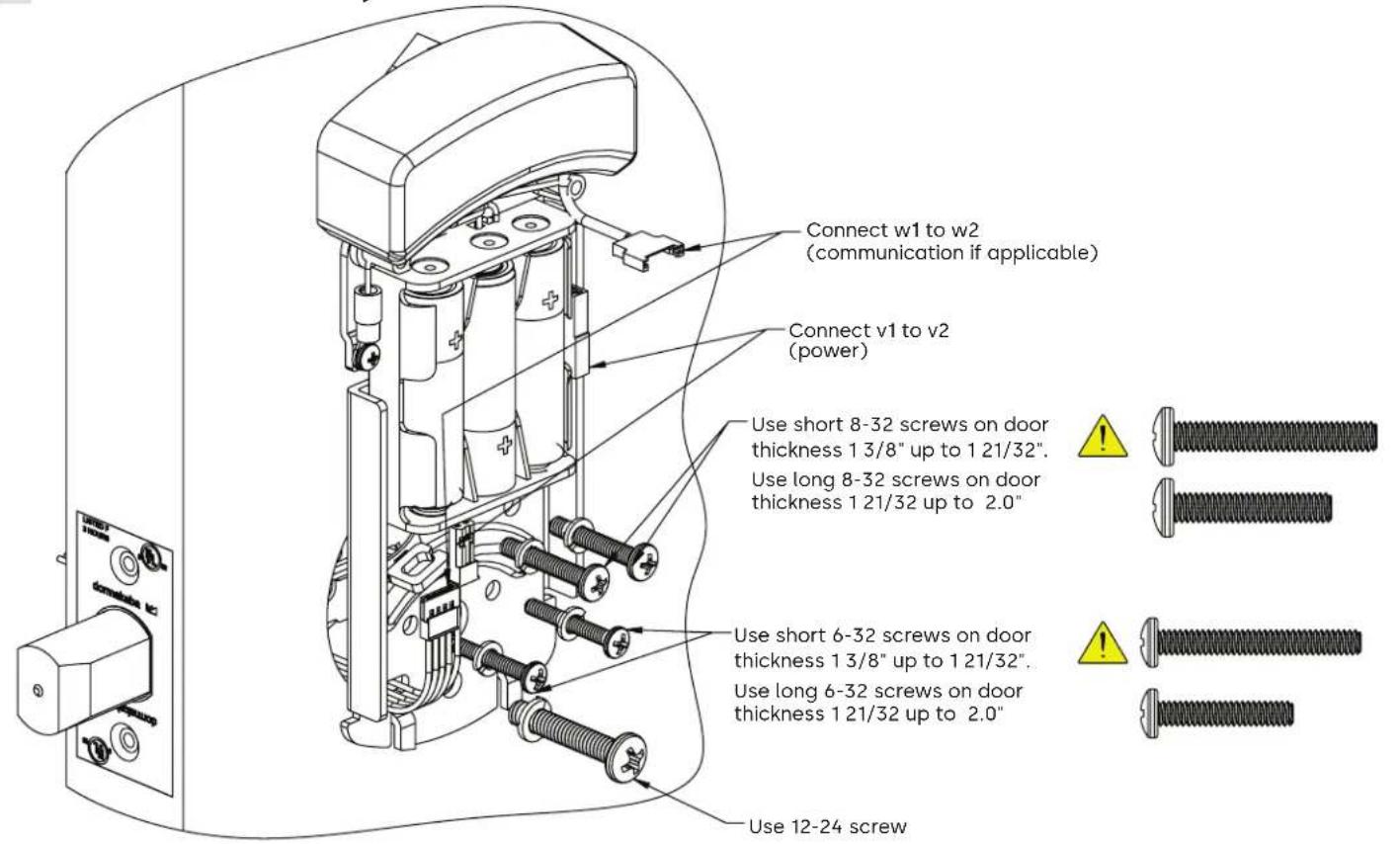
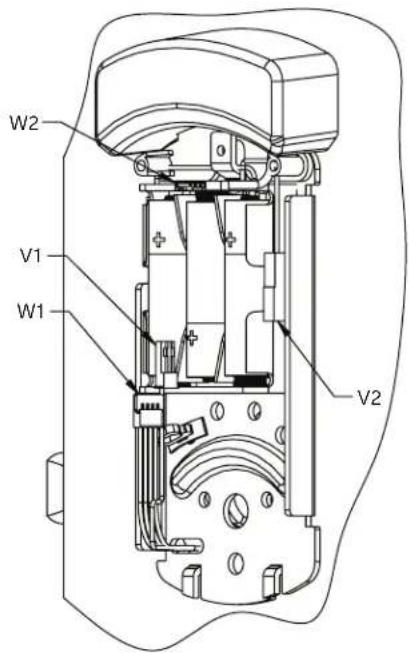
- Before tightening the screws verify functionality by extracting and retracting the Deadbolt. The dead bolt should move smoothly.
- All screws shall be thighten properly.
- Connect batteries, v1 to v2, after tightening all screws and wiring w1 & w2.
- Longer screw available for door over 2" to 2.5" Please order hardware kit 062-515743.
- Warning: using the long screw for door below 1 21/32" will damage the mechanism.
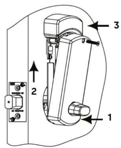
10 Install inside cover

11 Lock Programming

IMPORTANT
If your lock is already pre-programmed, you can go directly to section 3 below. Otherwise, follow the instructions in sections 1 and 2 below to program the lock.
1. Maintenance unit
To program the lock, you will need a Maintenance Unit running the Oracode application and the correct door configuration. You will need to login on the dormakaba e-code website (www.kaba-ecode.com) with a valid Username and Password in order to create the door and download it to the Maintenance Unit. If necessary, contact the dormakaba Technical Support Hotline (1-888-217-5654 US & Canada), (1-514-340-9025 International) or contact your Oracode representative for assistance.
2. Lock programming
Program the lock using the Oracode Maintenance Unit.
3. Code generation
Generate a valid code for this door on the www.kabaecodewireless.com website. You will need to login with a valid Username and Password in order to generate codes
4. Code entry and access
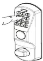
Enter the valid code on the lock keypad. A short beep can be heard and the green LED flashes for each key pressed. You will hear a longer beep and see a longer green LED flash when the code is accepted. The outside turn knob is then engaged for several seconds (5 to 15 seconds, depending on the configuration). If a red LED flashes and a low-pitch beep is heard when the code is entered, this indicates that the code is refused.
1

2


3


IMPORTANT
Make sure that the door is programmed properly and a valid code is accepted. If a valid code is not accepted, contact the dormakaba Technical Support Hotline.
4
12 Testing the operation of the lock

WARNING
Perform all the following with the door open.
- Project the dead bolt if it is not projected.
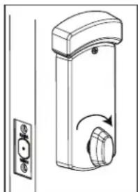
- Turn outside thumbturn, the deadbolt must not retract. See Fig. 1.
- Enter code.
- Retract dead bolt from outside. See Fig. 2.
- Wait 15 seconds.
- Rotate outside thumbturn to project the dead bolt.
- Rotate inside thumbturn to retract the dead bolt. See Fig. 3 & Fig. 4.


13 Testing the mechanical override (with door open)

14 Cover the key hole

- Project the dead bolt from outside or inside.
- Insert key and rotate it clockwise until it stops. See Fig. 4 & Fig. 5.
- Rotate outside thumbturn to retract the dead bolt. See Fig. 6.
NOTE: The key override always rotates clockwise
15 Maintenance when required
1. Time programming
The time is set automatically in the lock when the lock is programmed. The Oracode lock time should then be reset every year with the Maintenance Unit to ensure accurate time.
The lock has an internal battery back-up that keeps the internal time accurate for a minimum of four weeks when the lock's batteries are disconnected. If this period is surpassed and the lock time is lost, the green LED will blink twice after a valid code is entered, and the red LED will blink twice after a code is refused. This indicates that the time must be reset with the Maintenance Unit.
2. Reset to factory default
NOTE: You will need to reprogram the lock with a Maintenance Unit after you perform a Reset to Factory Default.
Perform the following steps to erase a lock's configuration and restore the default factory settings.
- Remove the inside cover and remove the batteries.
- After 1 minute, re-install the batteries. The green LED should blink quickly for 15 seconds.
- Press #,#,# while the green LED is blinking. The green and red LED should blink one after the other for 15 seconds.
- Press 1, 2, 3, 4, 5, 6 while the red and green LEDs are blinking. You will hear a longer beep and see a longer green LED flash when the code is accepted and the default factory setting are restored. If a red LED flashes and a low-pitch beep is heard, this indicates that the code is refused.
ORACODE 480i SERIES - Wireless Lock with Smart Controller
16 Oracode smart controller installation
1. Smart controller positioning
- Avoid placing the Smart Controller in close proximity (< 5 feet / 2 m) to a Wi-Fi device.
- Position the Smart Controller within 33 ft / 10 meters of the lock.
- Avoid heavy obstruction between the Smart Controller and lock (e.g., metallic or concrete wall or floor).
- Avoid placing the Smart Controller close to metallic objects (e.g., metallic table, refrigerator, filing cabinets, etc.).
2. Smart controller connection
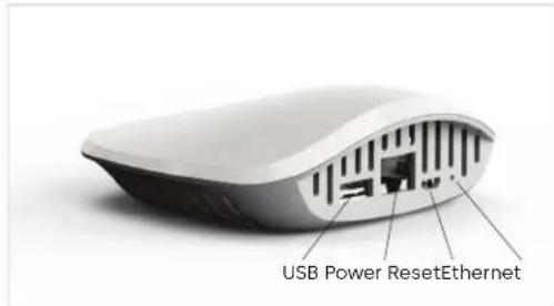
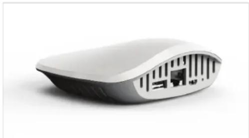
- Connect the Smart Controller to the Internet modem/router using the Ethernet Cable.
- Boot up the Smart Controller by connecting the Power Adapter.
- The Smart Controller will perform any necessary updates during the boot-up process, and the green LEDs on the top of the Smart Controller will come on (no specific order). The boot-up process can take from 30 seconds to a few minutes.
- Wait until all green LEDs are on. This confirms the Smart Controller has successfully performed all necessary updates and is ready to connect to the Oracode Server.
NOTE: The ZigBee LED may not illuminate during the initial installation. This is normal in most situations. Proceed with Wireless Lock Activation.
Smart Controller Front

Smart Controller Back
Power adaptor & Ethernet cables

17 Wireless lock activation (put on-line)
1. Activation code generation
- Log on to your Oracode Live account (www.kabaecodewireless.com).
- Go to 'Door Monitoring & Management' then to 'Door Monitoring'.
- Within the 'Door Monitoring' module, select the door to be activated from the door list, and click the 'Activate as Wireless' button.
- Select the Time Zone where the controller & lock will be located. The Network Name will be populated automatically, using the Door name as its basis. This can be edited if need be. Click on the 'Save Changes' button.
- When you click the 'Save Changes' button, the Activation number will be provided.
- Use this number to complete the Activation Process in the following steps 17.2 (for Oracode Live) or 17.3 (for BeHome247).
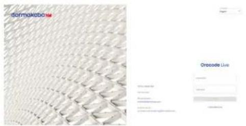
Oracode Live

Wireless lock activation (put on-line)17
2. Activation process (with Oracode Live)
- Once the Activation number is provided, a new field will be presented where the Smart Controller's MAC address is to be entered.
- Enter the controller's MAC address (located on Bottom Label), and then click the "Enable Discovery Mode" button.
- The Smart Controller will be in ZigBee "Join" mode for 10 mins, and the ZigBee LED on the Smart Controller will be blinking.
- On the lock keypad, press * # * # and enter the 8-digit Activation Code to start the activation process.
- The lock's green LED will blink once at the beginning of the activation process (the activation process could last from a few secs to 2 mins).
- A green LED and a high-pitch beep indicates successful connection to the Oracode Server.
- A series of silent green LED blinks will follow. This is the lock programming being received from the Oracode Server. Once there are no more silent green LED blinks, the lock programming is complete.
- The Door Details page within Oracode Live for the activated door will be displayed, confirming that the Activation Process is complete.
- A red LED and a low-pitch beep at the end of the activation process indicates a failure. In the case of a failure, follow the below steps and then start the activation process again:
- Remove only one battery, wait 5 seconds and insert it again. As soon as the green led light begins to blink, press ###123456, a beep will be heard with a green light indicating that it was successful.
Oracode Smart Controller

dormakaba

051-e450
Powered by Ezlo
Input: 5V\~3A
Polarity: ⊙◎◎
Made in China
MAC: XX:XX:XX:XX:XX
WIFI: XXXXXXXX
SSID: wifi_XXXXXXX
FCC ID: 2AIYWPLUS450 IC: 26382-PLUS450 CAN ICES-003(B)/NMB-003(B)
Serial:XXXXXXXX


18 Oracode smart controller diagnostics
Smart Controller Back
1. Lock to smart controller "connection" status
- Entering # # # 2 on the lock keypad triggers a "Lock to Smart Controller" status test.
- A green LED and a high-pitched beep at the end of the test indicates the lock is connected to the Smart Controller.
- A red LED and a low-pitched beep at the end of the test indicates the lock is not connected to the Smart Controller.
2. Wireless link test
- This test requires the Smart Controller to be put in ZigBee "Join" mode (by enabling "Join" on the kabaecodewireless website) Can be done at the moment to link a lok
- Entering # # # 1 on the lock keypad triggers a "Lock to Gateway" wireless link test.
- A green LED and a high-pitched beep at the end of the test indicates a good link quality (success).
- A red LED and a low-pitched beep at the end of the test indicates a bad link (fail).
- If the Wireless Link Test fails, improve the Smart Controller positioning (see 16.1) and re-execute the Wireless LinkTest.
3. Smart controller reset to factory default
NOTE: You will need to get a new Activation Code from the Oracode Live web site to re-activate the lock (see page 08) after you perform a Reset to Factory Default of the Smart Controller.
- Use a paperclip or pencil to press the "Reset" button (on the back of the Smart Controller) Press and hold the button for 15 seconds, then wait a few minutes until you get the steady Blue Light pattern (to see this pattern the gateway must be connected to the network).

Door
Hardware

Electronic
Access & Data

Mechanical
Key Systems

Lodging
Systems

Entrance
Systems

Safe
Locks

Service

dormakaba.com
dormakaba USA Inc.
6161 E. 75th Street
Indianapolis, IN 46250
T: 1 888 217 5654
T: +1 514 340 9025 (international)
dormakaba.us
Full service from 8:30 am to 7:00 pm
Eastern Time, Emergencies 24/7
Email: techsupport.lgs.ca@dormakaba.com
Lodging Support: dormakabalodgingsupport.com
- WARNING
- TOOLS REQUIRED
- PARTS LIST
- 4 KEY OVERRIDE CYLINDER
- 5 ADJUST LOCK HANDING ON OUTSIDE HOUSING ASSEMBLY
- LEFT HAND (LH)
- 6 ASSEMBLE TAIL PIECE REMOVE INSIDE COVER
- 8 ASSEMBLE OUTSIDE HOUSING
- 11 LOCK PROGRAMMING
- IMPORTANT
- MAINTENANCE UNIT
- LOCK PROGRAMMING
- CODE GENERATION
- CODE ENTRY AND ACCESS
- 12 TESTING THE OPERATION OF THE LOCK
- 15 MAINTENANCE WHEN REQUIRED
- TIME PROGRAMMING
- RESET TO FACTORY DEFAULT
- ORACODE 480I SERIES - WIRELESS LOCK WITH SMART CONTROLLER
- 16 ORACODE SMART CONTROLLER INSTALLATION
- SMART CONTROLLER POSITIONING
- SMART CONTROLLER CONNECTION
- 17 WIRELESS LOCK ACTIVATION (PUT ON-LINE)
- ACTIVATION CODE GENERATION
- WIRELESS LOCK ACTIVATION (PUT ON-LINE)17
- ACTIVATION PROCESS (WITH ORACODE LIVE)
- 18 ORACODE SMART CONTROLLER DIAGNOSTICS
- LOCK TO SMART CONTROLLER "CONNECTION" STATUS
- WIRELESS LINK TEST
- SMART CONTROLLER RESET TO FACTORY DEFAULT
Brand : Dormakaba
Model : Oracode 480
Category : Electronic lock