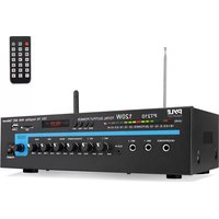
USER MANUAL PT210 Pyle


natural_image
Collection of various geometric and symbolic icons in red, black, and white (no text or labels)

natural_image
Row of red decorative symbols including stars, arrows, and triangles (no text or labels)
70V Output & Mic Talkover
USER MANUAL
INTRODUCTION
Your New PYLE PT210 PA AMPLIFIER gives you the power and versatility you need in a professional sound system. The amplifier's wide frequency response makes it suitable for amplifying music or vocal program material. It can be used for live bands, office paging systems, public announcements, or a variety of other installations. Please read this manual throughly before you attempt to set up and use the amplifier. It contains a range of installation suggestions as well as instructions to ensure safe usage. Installed properly, you can expect years of trouble-free service from this product.
FEATURES AND CONTROLS
FRONT PANEL

REAR PANEL
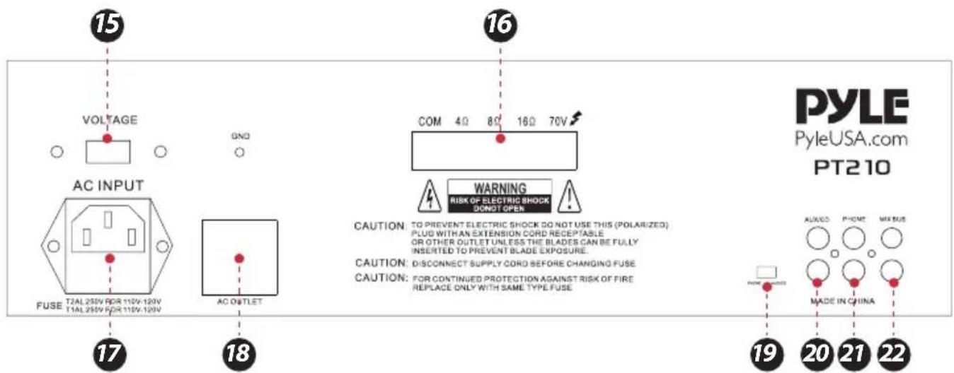
- POWER SWITCH: Press to switch the power unit ON or OFF.
-
Phone Jack: Connect a pair of stereo headphones for private listening or cueing (monitoring) sound prior to "airing" it.
-
MIC 1 & MIC 2 Jack: Allows you to connect up to two 6.35mm type microphone.
-
LED Level Display Meter
-
Three Input Sources Mixing Controls: Controls the sound level for each of the audio input sources.
PHONO/AUX: Select and connect an alternative high level (AUX/CD) or low level (PHONO) audio sound source.
- AUX-IN: Input to connect an external audio device
- BASS: Increases or reduces the bass frequencies of the signal
- MID KNOB: Increases or reduces the mid-low frequencies of the signal
- HIGH KNOB: Increases or reduces the high frequenciess of the signal
- MASTER VOLUME: Controls the overall volume of the amplifier
- SD Card Input
- USB Flash Drive Input
- LED Display: Displays the output level and selected input
-
MODE, PLAY, PREV and NEXT Function Control buttons:
-
MODE Button: For audio selection like WIRELESS BT/SD/LINE IN
- PLAY/PAUSE BUTTON: Play and Pause control button
- PREV/NEXT: Quick backward or next song
- Voltage Selector: Select the voltage of AC power input source. The amplifier has selectable input voltage from 110V/60Hz which is the standard in USA and CANADA. You can also switch the input voltage to 230V/50Hz for EUROPEAN operation. Please make sure the switch is in the proper position before operating otherwise severe damage will result which is not covered by the warranty. Please also replace the fuse with proper rating in this situation.
- Push-Terminal Connectors: Let you easily connect speaker wires directly to the amplifiers.
- AC INPUT
- Unswitched AC Accessory Outlet: 300W MAX.
- PHONO and AUX/CD Input Selector: Lets you select the input source you want to connect to the amplifier.
- PHONO Input Jack: You can connect a low level audio input source, such as a magnetic cartridge turntable to the L PHONO and R PHONO jacks.
- PHONO and AUX/CD Input Selector: Lets you select the input source you want to connect to the amplifier.
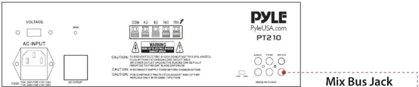
- MIX BUS Jack: Allows you to connect another PT210 to this jack to double the size of your PA system.
INSTALLATION GUIDELINES
Connecting the GND (GROUND) screw terminal
If you connect a low level audio input source (turntable) to the PHONO, please connect your turntable's ground wire (usually black or green) to the amplifier's GND terminal, to avoid a low frequency hum. You can also use this screw to ground any other system connection.
- Microphones (up to two simultaneously)
- Compact Disc (CD) player
• Cassette, Reel-to-Reel or other tape player
- Radio Tuner
• Magnetic Cartridge Turntable
Connecting microphones
The MIC 1 and MIC 2 jacks permit you to connect two microphones with 6.35mm plug.

Connecting a CD or tape player, or tuner
In this Situation, set the PHONO and AUX/CD SELECTOR switch to the AUX/CD

Connecting a turntable
In this Situation, set the PHONO and AUX/CD SELECTOR switch to the PHONO.

Speaker Connections
One or more speakers (4, 8, or 16-Ohm) speakers can be connected to the amplifier with or without transformers. However, before you connect any speaker to the amplifier, the total speaker impedance must be calculated in order to avoid damage to the amplifier. A total speaker impedance greater than 16 Ohms or less than 4 Ohms can be cause this damage to occur.
To begin with, in order to ensure equal volume from each speaker, all connected speakers should have the same impedance. A proper total impedance with the 4 to 16 Ohms range can be achieved by combining series and paralleled speaker connections. Please see the diagrams which follow the same impedance.
Finally, always use the shortest length of speaker wire possible of proper gauge. Usually, 18-gauge wire is adequate for lengths under 25 feet, while 16-gauge is used for greater lengths.
System 1: Single speaker system
- Connect the speaker (-) terminal to the amplifier COMMON terminal
- Depending on the speaker being used, connect the speaker (+) terminal to the amplifier's 4-Ohm, 8- Ohm or 16-Ohm amplifier terminal.
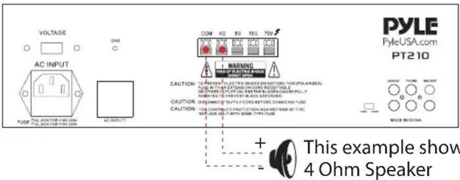
System 2: Two (or more) speakers in series
- Connect the LEFT SPEAKER (-) to the amplifier COMMON terminal.
- Connect the LEFT SPEAKER (+) to the RIGHT SPEAKER (-).
- Connect the RIGHT SPEAKER (+) to the amplifier's 4-Ohm, 8-Ohm, or 16-Ohm terminal, depending on the TOTAL IMPEDANCE of the two speakers. If each speaker has an impedance of 8 Ohms, the total speaker impedance in this series configuration is 16 Ohms.

This example shows two 4 Ohm Speaker, the total impedance is 8 Ohms.
NOTE: ADDITIONAL SPEAKERS MAY BE INCLUDED IN SERIES, BUT IT IS NECESSARY TO CALCULATE TOTAL IMPEDANCE, AND CONNECT THE SPEAKER CIRCUIT TO A TERMINAL OF APPROPRIATE IMPEDANCE. FOR EXAMPLE, IF THREE SPEAKERS OF 4-OHM ARE USED, TOAL IMPEDANCE IS 12 OHMS, YOU SHOULD CONNECT TO THE 16-OHM TERMINAL.
System 3: Two (or more) speakers in parallel
- Connect the LEFT SPEAKER (-) to the RIGHT SPEAKER (-).
- Connect BOTH the LEFT SPEAKER (-) and the RIGHT SPEAKER (-) to the amplifier COMMON terminal.
- Connect the LEFT SPEAKER (+) to the RIGHT SPEAKER (+).
- Connect BOTH the LEFT SPEAKER (+) and RIGHT SPEAKER (+) to the amplifier 4-Ohm, 8-Ohm or 16- Ohm terminal, depending on the TOTAL IMPEDANCE of the two speakers. If each speaker has an impedance of 8-Ohm, the total speaker impedance in this parallel configuration is 4 Ohms.

System 4: Four speakers in series/parallel combination
- Group the four speakers into two pairs.
- Connect each pair of speakers in SERIES (see system 2 above).
If you connect 8-ohm speakers, the total impedance of each pair is 16 ohms.
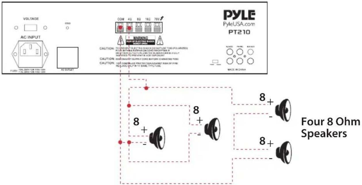
- Connect the two pairs of speakers in PARALLEL, If you connect 8-ohm speakers, the total impedance of both pairs is 8 ohms.
Note: If each of the four speakers is 8 ohms, the total speaker impedance of the combined series/parallel connection described above is also 8 ohms. Likewise, the total speaker impedance is 4 or 16 ohms, if the speakers are 4 or 16 ohms respectively.
-
Connect the speakers (-) terminals to the amplifier's COMMON terminal.
-
Connect the speakers' (+) terminals to the amplifier's 4-Ohm, 8-Ohm, or 16-Ohm terminal, depending on the TOTAL IMPEDANCE of the FOUR SPEAKERS.
See the chart below for some samples system suggestions:
COMBINATION OF TWO SERIES PAIRS IN PARALLEL
| SERIES TO EACH PAIR (net impedance) | PARALLEL TO TWO PAIRS (net impedance) | TOTAL IMPEDANCE IN THIS TYPE | Use this amp terminal |
| 4-OHM + 4-OHM (8 OHMS) | 8-OHM + 8-OHM (4 OHMS) | 4-OHM | 4-OHM |
| 8-OHM + 8-OHM (16 OHMS) | 16-OHM + 16-OHM (8 OHMS) | 8-OHM | 8-OHM |
| 16-OHM +16-OHM (32 OHMS) | 32-OHM + 32-OHM (16 OHMS) | 16-OHM | 16-OHM |
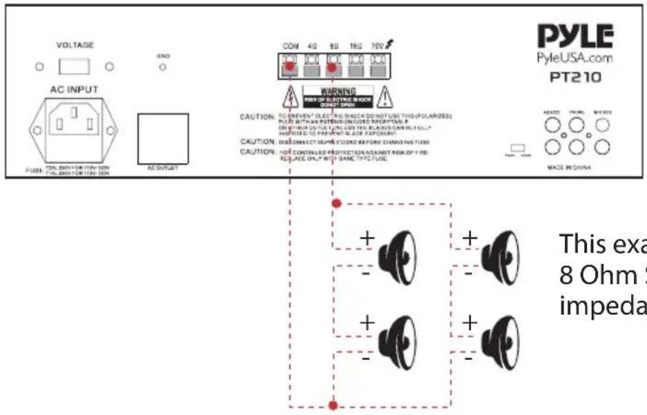
This example shows four 8 Ohm Speaker, the total impedance is 8 Ohms.
SERIES/PARALLEL VARIATIONS
Although the description above is for combining TWO SERIES PAIRS in a PARALLEL hook up, you may also select to combine a SERIES PAIR and a PARALLEL PAIR in a PARALLEL hook up. Simply be sure you have properly calculated the total impedance, and connect the (+) speaker circuit wire to the proper amp terminal. For example, if you use a SERIES PAIR of 8-Ohms speakers (the total impedance is 16 ohms) and a PARALLEL PAIR of 8-Ohms speakers (the total impedance is 4 ohms) in a PARALLEL hook up, the TOTAL IMPEDANCE of this system is 3.2 OHMS, so you should connect the (+) speaker circuit wire to the 4-OHM terminal.
See the chart below for some samples system suggestions:
COMBINATION OF ONE SERIES PAIR AND ONE PARALLEL PAIR IN PARALLEL
| SERIES TO ONE SPEAKER PAIR (net impedance) | PARALLEL TO ONE SPEAKER PAIR (net impedance) | TOTAL IMPEDANCE COMBINING TWO PAIRS IN PARALLEL | Use this amp terminal |
| 8-OHM + 8-OHM (16 OHMS) | 8-OHM + 8-OHM (4 OHMS) | 3.2 OHMS | 4-OHM |
| 16-OHM + 16-OHM (32 OHMS) | 8-OHM + 8-OHM (4 OHMS) | 3.6 OHMS | 4-OHM |
| 4-OHM + 4-OHM (8 OHMS) | 16-OHM + 16-OHM (8 OHMS) | 4.0 OHMS | 4-OHM |
| 8-OHM + 8-OHM (16 OHMS) | 16-OHM + 16-OHM (8 OHMS) | 5.3 OHMS | 8-OHM |
This example shows for the first three systems in chart. In this case, 4-Ohm terminal is used your system impedance may be varied depending on the impedances of the individual speakers, and may require hook up to the 8 or 16 Ohms terminal.
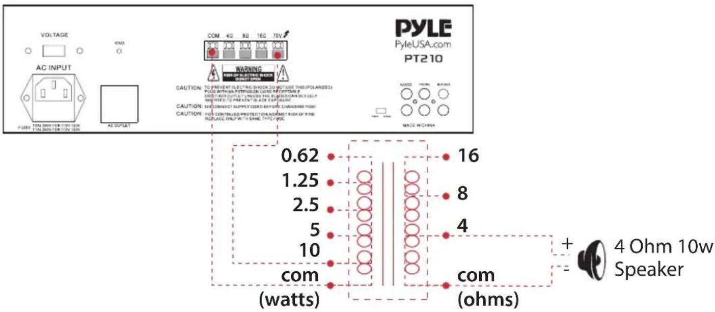
- Locate the input taps on your transformer. These taps are on side of the transformer, and are rated in watts, 10, 5, 2.5, 1.25 or 0.62. Usually, each speaker in a system uses the same wattage tap. Connect the selected tap to the amplifier 70V RMS terminal. If you wish a particular speaker to have a higher volume level, connect the wire from 70V RMS to a higher wattage tap on the transformer.
- Connect the transformer's COMMON tap on the primary side to the amplifier COMMON terminal.
- Connect the speaker's (+) terminals to the transformer's secondary tap that matches the speaker's TOTAL IMPEDANCE. Locate on the opposite side of the transformer, these secondary taps are outputs, and are rated in Ohms 4, 8 or 16.
- Connect the speaker's (-) terminals to the transformer's COMMON tap on the secondary side.
NOTE:
- Before connecting the speakers, please be sure the total wattage of the primary tap you use does not exceed the amplifier's maximum power rating.
- Avoid, where possible, multiple connections to the 70V RMS and COMMON terminals.
Using Headphones
To listen privately, or to monitor sound sources, connect a pair of low impedance stereo headphones (not supplied) with 6.35mm plug into the PHONES jack on the amplifier front panel.
Please listen safely. Follow these recommendations:
Do not listen at extremely high volume levels. Extended, high-volume listening can lead to permanent hearing loss. Always start with the volume control set to a LOW level BEFORE you put the headphones on. Then gradually increase the volume as necessary.
Connecting to standard AC power
After making all other connections, set the POWER switch to OFF position. Then connect the power cord to a standard AC outlet.
Connecting to 4A/12V DC power
You can power the amplifier from your vehicle's 12-volt battery. Connect the supplied DC power cable's barrel plug to DC 12V IN jack on the amplifier, and then connect the cable's other end to the 12-volt accessory socket on the vehicle, such as the cigarette-lighter socket.
CAUTIONS:
PLEASE UNPLUG THE AC POWER CORD BEFORE CONNECTING THE DC POWER CABLE FOR THIS 12V POWER USAGE, AND DISCONNECT THE DC POWER CABLE BEFORE PLUGGING IN THE AC POWER CORD FOR AC POWER USAGE.
THE VEHICLE USING THIS POWER SOURCE MUST HAVE A NEGATIVE GROUND ELECTRICAL SYSTEM. IF YOU ARE NOT SURE OF IT, PLEASE CHECK WITH YOUR VEHICLE'S DEALER.
Turning the amplifier ON
- Turn on the audio input source equipment which is connected to the amplifier INPUT jack.
- Set all volume levels (MASTER, MIC 1, MIC 2, and PHONO/AUX) to their minimum level settings.
- Press the power switch to turn the amplifier on.
- Adjust the controls of MIC 1, MIC 2, and PHONO/AUX to the achieve desired volume and balance. Using the LED power meter The meter LED position indicate the amplifier output power.
Using the MASTER volume control
The MASTER volume control increases or decreases output level gain. To obtain best performance with the least distortion, be sure to adjust the output level so that the LED meter does not continually exceed the right extreme of the meter's range.
CAUTION: Setting output level too high can overdrive the amplifier, causing permanent damage.
Using the MIX BUS jack
You can connect another PT210 to this jack to double the size of your PA system. This lets you use up to four microphones and two turntables (or two auxiliaryies) sound sources. Use a shield cable with phono plugs at each end, and connect the cable between the MIX BUS jacks on the back of two amplifiers. For the best results, do not use a cable longer that 6 feet.

Remote control
- Press this button to turn on the MP3
- In FM mode, press this two buttons to select previous or next channel.
- Press these two buttons to select the previous or next track in USB or SD or Wireless BT mode
- Volume up or down
- Press the numbers to select the tracks directly. The unit takes 1-2 seconds to response in USB or SD mode.
- Press this button to select repeat mode: One and all.
- Press this button to select the playing mode, such as USB/SD/FM/WIRELESS BT
- EQ function, if the mp3 with EQ
- Play and pause function for MP3

Features:
• Blue LED Screen for Media Playback Information
- Double Decoder Digital Media Function with Remote Control
- Compatible with MP3/WMA
• Wireless BT Streaming, FM Radio
• Built-in USB & SD Card Readers
• Power On/Off with LED Indicator
• 1/4" Phone Jack
- LED Level Display
• Master Volume Control
• High/Mid/Low Tone Controls
- Front 3.5mm AUX CD Input Jack
- MIC 1 Talkover
• Phono/Aux Volume Control
• Mic 1 Mic 2 Volume Controls
• Mic 1 Mic 2 6.35mm Connectors
• Voltage Selector 110/220V
- Removable AC Cord
• Unswitched AC Outlet
- Mix Bus Jacks
- Phono/Aux/RCA Input Jacks
- Phono/Aux Input Selector
- Variety of Speaker Outputs Terminal
Wireless BT Connectivity:
• Built-in Wireless BT Music Streaming Receiver
- Compatible with All of Your Favorite Wireless BT Devices (iPhone, Androids, Smartphones, iPad, Tablets, etc.)
- Wireless BT Version: 5.0
• Wireless BT Network Name: 'PYLEUSA'
What's in the Box:
- FM Antenna
- Remote Control
• Microphone PA Mono Amplifier
Technical Specs:
• Power Output:120W
• Power Supply: 120/240 Switchable, 50/60Hz
• Impedance: 4-8 Ohm
- Fuse: 3A
• THD: 1%
• Harmonic Distortion: 0.3%
- Input sensitivity: 150mV (Max Output: 6000mV)
- Bass: +/-10dB (100 Hz), Treble: +/-10dB (10KHz)
• Frequency Response: 100Hz-20KHz
• Signal to Noise Ratio: >78dB
- Battery Operated Remote Control, Requires (1) x 'CR-2032' Battery (Included)
- Product Dimension (L x W x H): 12.6" x 9.8" x 3.5"-inches

WARNING:
This product can expose you to a chemical or group of chemicals, which may include "Nickel Carbonate" which is known in the state of California to cause cancer, birth defects, or other reproductive harm. For more info, go to https://www.p65warnings.ca.gov/.
PYLE
PyleUSA.com

natural_image
Illustration of a laptop with a red checkmark icon on screen (no text or symbols)
VISIT US ONLINE:
Have a question?
Need service or repair?
Want to leave a comment?
PyleUSA.com/ContactUs

Questions? Issues?
We are here to help!
Phone: (1) 718-535-1800
Email: support@pyleusa.com