
MOKR124SS31A - Beer dispenser Marvel - Free user manual and instructions
Find the device manual for free MOKR124SS31A Marvel in PDF.


| Product Type | Beer Dispenser (Kegerator) |
| Brand | Marvel |
| Model | MOKR124SS31A |
| Power Supply | 115 V, 15 A, 60 Hz, dedicated circuit |
| Refrigerant | R600a (Isobutane), flammable |
| Max Keg Capacity | 1/2 barrel, 1/4 barrel, or 2 x 1/6 barrels |
| CO₂ Tank Capacity | 5 lb (included, empty) |
| Regulator Type | Single or dual gauge (depending on tower) |
| Tower Material | Polished stainless steel |
| Dispense Towers | Single or double (depending on model) |
| Shelves | 2 adjustable shelves |
| Temperature Control | For beer: 34°F–42°F; for storage: as needed |
| Drain System | Bottle drain kit with removable grate |
| Installation Options | Freestanding or undercounter (requires cutout) |
| Safety Features | Grounded plug, child safety, flammable refrigerant precautions |
| Cleaning | Use soap and water; do not use abrasive cleaners |
| Warranty | 1 year limited parts and labor; 5 year sealed system |
| Customer Service | 616.754.5601 or www.marvelrefrigeration.com |
| Parts Ordering | partsformarvel.com |
| Manual | Included, 23 pages |
Frequently Asked Questions - MOKR124SS31A Marvel
Contact Marvel at 616.754.5601.
User questions about MOKR124SS31A Marvel
0 question about this device. Answer the ones you know or ask your own.
Ask a new question about this device
Download the instructions for your Beer dispenser in PDF format for free! Find your manual MOKR124SS31A - Marvel and take your electronic device back in hand. On this page are published all the documents necessary for the use of your device. MOKR124SS31A by Marvel.
USER MANUAL MOKR124SS31A Marvel
natural_image
Outdoor resort area with palm trees, a thatched hut, and a wooden patio table (no visible text or symbols)FOR MODEL # MOKR124
Important Safety Instructions
Warnings and safety instructions appearing in this guide are not meant to cover all possible conditions and situations that may occur. Common sense, caution, and care must be exercised when installing, maintaining, or operating this appliance.
Recognize Safety Symbols, Words, and Labels.

WARNING
WARNING - You can be killed or seriously injured if you do not follow these instructions.

CAUTION
CAUTION-Hazards or unsafe practices which could result in personal injury or property / product damage.
NOTE
NOTE-Important information to help assure a problem free installation and operation.

WARNING
State of California Proposition 65 Warning: This product contains one or more chemicals known to the State of California to cause birth defects or other reproductive harm.

WARNING
State of California Proposition 65 Warning: This product contains one or more chemicals known to the State of California to cause cancer.

WARNING
WARNING-This unit contains R600a (Isobutane) which is a flammable hydrocarbon. It is safe for regular use. Do not use sharp objects to expedite defrosting. Do not damage refrigerant circuit.
Tip: Click on any section below to jump directly there
Safety
Important Safety Instructions
Installation
Unpacking Your Appliance
Electrical
Operating Instructions
Using Your Beverage Dispenser
Energy Savng Tips
Service
Obtaining Service
Product Liability
Ordering Replacement Parts
R600a Specifications
System Diagnosis Guide
Warranty

WARNING
EXCESSIVE WEIGHT HAZARD
Use two or more people to move product. Failure to do so can result in personal injury.
Remove Interior Packaging
Your appliance has been packed for shipment with all parts that could be damaged by movement securely fastened. Remove internal packing materials and any tape holding internal components in place. The owners manual is shipped inside the product in a plastic bag along with the warranty registration card, and other accessory items.
Important
Keep your carton and packaging until your appliance has been thoroughly inspected and found to be in good condition. If there is damage, the packaging will be needed as proof of damage in transit. Afterwards please dispose of all items responsibly.

WARNING
WARNING - Dispose of the plastic bags which can be a suffocation hazard.
Note to Customer
This merchandise was carefully packed and thoroughly inspected before leaving our plant. Responsibility for its safe delivery was assumed by the retailer upon acceptance of the shipment. Claims for loss or damage sustained in transit must be made to the retailer.
NOTE
DO NOT RETURN DAMAGED MERCHANDISE TO THE MANUFACTURER - FILE THE CLAIM WITH THE RETAILER.

CAUTION
If the appliance was shipped, handled, or stored in other than an upright position for any period of time, allow the appliance to sit upright for a period of at least 24 hours before plugging in. This will assure oil returns to the compressor. Plugging the appliance in immediately may cause damage to internal parts.

WARNING
WARNING - Help Prevent Tragedies
Child entrapment and suffocation are not problems of the past. Junked or abandoned refrigerators are still dangerous - even if they sit out for "just a few hours".
If you are getting rid of your old refrigerator, please follow the instructions below to help prevent accidents.
Before you throw away your old refrigerator or freezer:
• Take off the doors or remove the drawers.
- Leave the shelves in place so children may not easily climb inside.
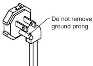
Figure 2
natural_image
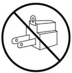
Prohibition sign showing a crossed-out electrical component (no text or symbols)Figure 3
Electrical Connection
A grounded 115 volt, 15 amp dedicated circuit is required.
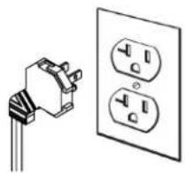
This product is factory equipped with a power supply cord that has a three-pronged, grounded plug. It must be plugged into a mating grounding type receptacle in accordance with the National Electrical Code and applicable local codes and ordinances (see Figure 4). If the circuit does not have a grounding type receptacle, it is the responsibility and obligation of the customer to provide the proper power supply. The third ground prong should not, under any circumstances, be cut or removed.
natural_image
Simple line drawing of an electrical outlet with two socket covers (no text or symbols)Figure 4
NOTE
Ground Fault Circuit Interrupters (GFCI) are prone to nuisance tripping which will cause the appliance to shut down. GFCI's are generally not used on circuits with power equipment that must run unattended for long periods of time, unless required to meet local building codes and ordinances.

WARNING
Electrical Shock Hazard
- Do not use an extension cord with this appliance. They can be hazardous and can degrade product performance.
- This appliance should not, under any circumstances, be installed to an un-grounded electrical supply.
- Do not remove the grounding prong from the power cord. (See Figure 2).
- Do not use an adapter. (See Figure 3).
- Do not splash or spray water from a hose on the appliance. Doing so may cause an electrical shock, which may result in severe injury or death.
Shelving
The unit is shipped with the (2) shelves taped in place in the upper and the lower shelf positions. Remove them from the refrigerator and arrange them as follows when setting up your unit.
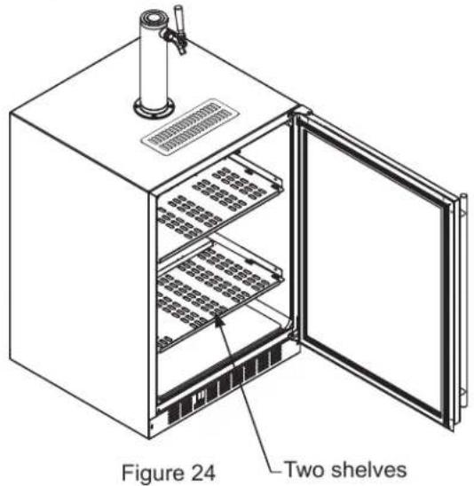
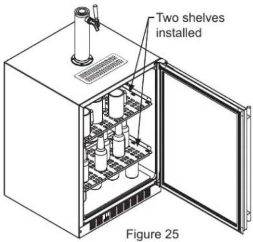
If you are not serving beer on tap, your keg dispenser can be used as a refrigerator by placing both shelves on the mounting brackets as shown in Figure 25. The shelves are marked upper and lower, The upper shelf should be placed in the top shelf position and the shelf marked lower should be placed in the bottom shelf position.

CAUTION
If you are using the appliance as a refrigerator for perishable foods, the set-point temperature should be set between 34^ F and 42^ F ( 1.2^ C and 5.7^ C).
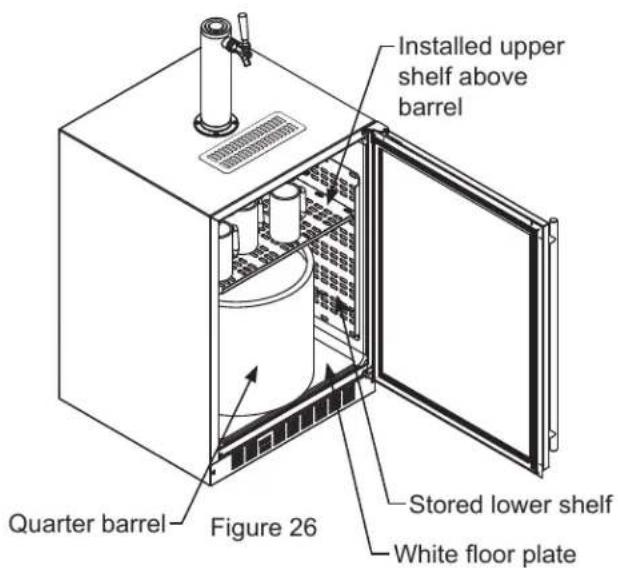
If you are using a quarter barrel of beer, you can add shelf space for keeping your mugs chilled. The quarter barrel must set on the floor, it cannot fit on the shelf, see
Figure 26. Be sure the white floor plate is in the bottom of the interior compartment before positioning the barrel.
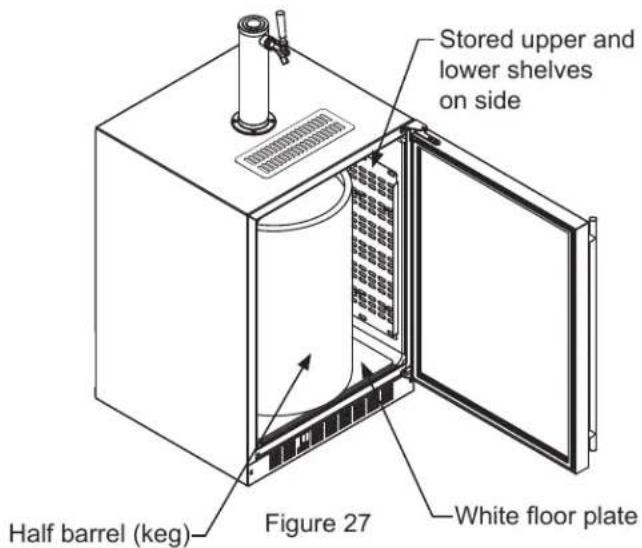
If you are using a half barrel (keg) or (2) 1/6 barrels, place the two shelves on the right side of the keg dispenser on the two mounting hooks for storage. (See Figure 27). Be sure the white floor plate is in the bottom of the interior compartment before positioning the barrel(s).
This beer dispensing unit will support one half ( 12 ) barrel or one quarter ( 14 ) barrel. The double draft tower units can support two sixth ( 16 ) barrels of beer. See chart below for quantity of beer in each barrel size.
| Barrel Sizes | |||
| 1/6 barrel | 1/4 Barrel | 1/2 Barrel | |
| Height | 23516" (59.2 cm) | 14^13/_16" (37.6 cm) | 23516" (59.2 cm) |
| Diameter | 914" (23.5 cm) | 17"(43.2 cm) | 17" to 1714" (43.2 to 43 cm) |
| Gallons | 5.23 | 7.75 | 15.5 |
| #12 ounce Glasses | 53 | 82 | 163 |
| Keg Size | #of kegs per 5 pound CO2Tank |
| 5 gallon Corny | 15 to 22 |
| 1/6 barrel | 14 to 21 |
| 1/4 Barrel | 10 to 14 |
| 1/2 Barrel | 5 to 7 |
Tools required for installation:
Flat bladed screwdriver
Phillips screwdriver
Pliers
Adjustable wrench or a 1 ^1/8 " open end wrench
12 " open end wrench

WARNING
CO _2 can be dangerous. If it becomes difficult to breathe and/or your head starts to ache, a high concentration of carbon dioxide may be present. Leave the area immediately.
• The CO_2 tank must always be connected to the regulator. Never connect the tank to the keg.
- The CO₂ tank must be securely mounted in the upright position. Secure it with the chain provided.
• Never drop or throw the CO_2 tank.
- Keep the CO_2 tank away from heat.
• Ventilate the area after a CO₂ leak.

CAUTION
Tap Equipment and Assembly
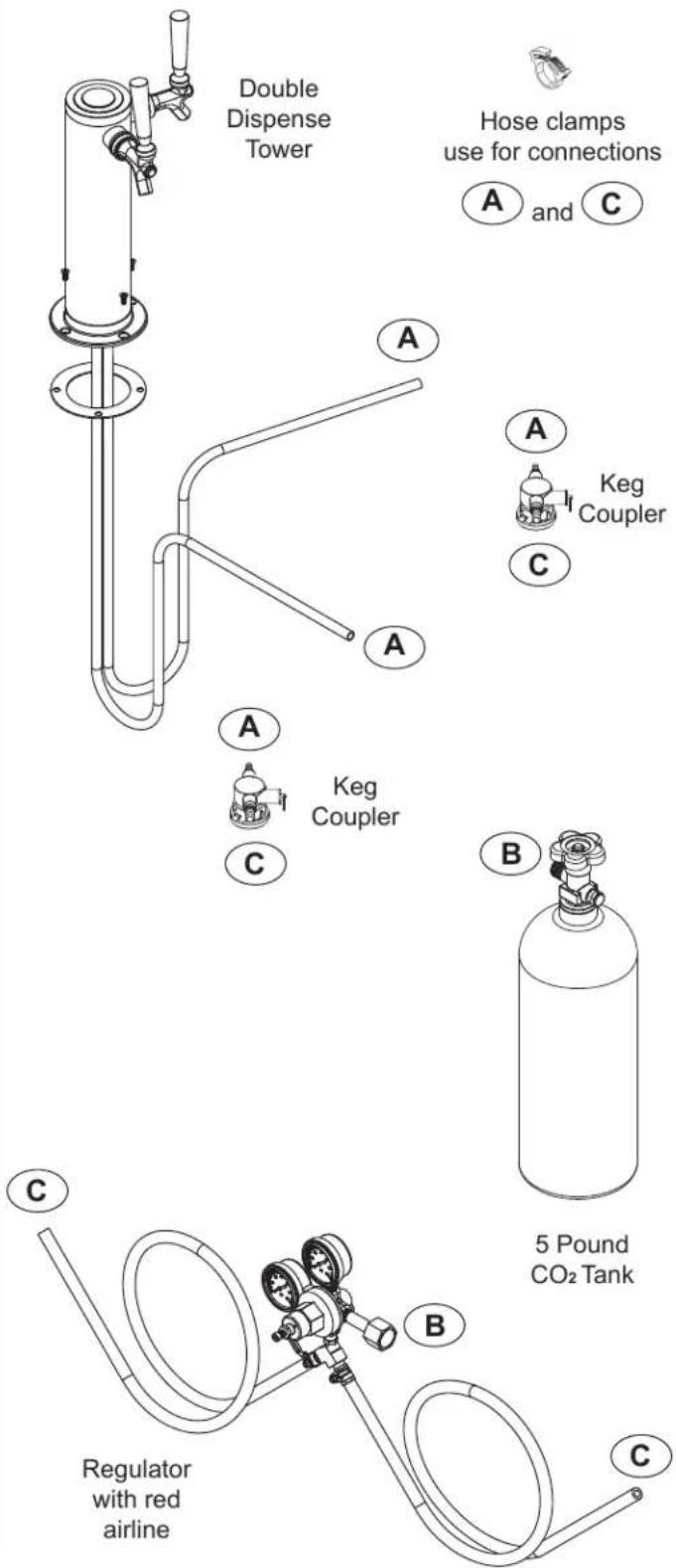
Your dispensing kit includes the following parts:
Polished stainless steel tower with clear beer line (single or double dispense)
Tower Gasket
Phillips oval head screws
Knob for Tower (Faucet Handle)
Keg coupler(s)
CO _2 regulator with red gas line(s) attached
Empty 5 pound CO₂ tank
Plastic clamp(s) large and small
Faucet wrench
-
Remove shelving and packaged components from the interior of the refrigerator before beginning the assembly process.
-
Take your empty 5 pound CO₂ tank to your local gas supply dealer to be filled. You can usually find them in your "yellow pages" under "Welding Supply" or "Fire Protection". One 5 pound tank can process many kegs (see table "D").
-
Tower Mounting: DO NOT REMOVE INSULATION INSIDE OF STAINLESS STEEL TOWER. INSULATION KEEPS BEER IN CLEAR LINE COLD AND FRESH.
Mounting Tower to Refrigerator Top: Remove the foam plug from the porthole and DO NOT reseal. Clearance in porthole is necessary for cold air to flow into the tower and keep the beer line cold.
Mounting Tower to Counter Top: Remove the foam plug from the porthole and use to "bridge" the gap between the top of the cabinet and the underside of the counter. Leave adequate clearance for cold air to flow into the tower and keep the beer line cold.
USING YOUR BEER DISPENSER
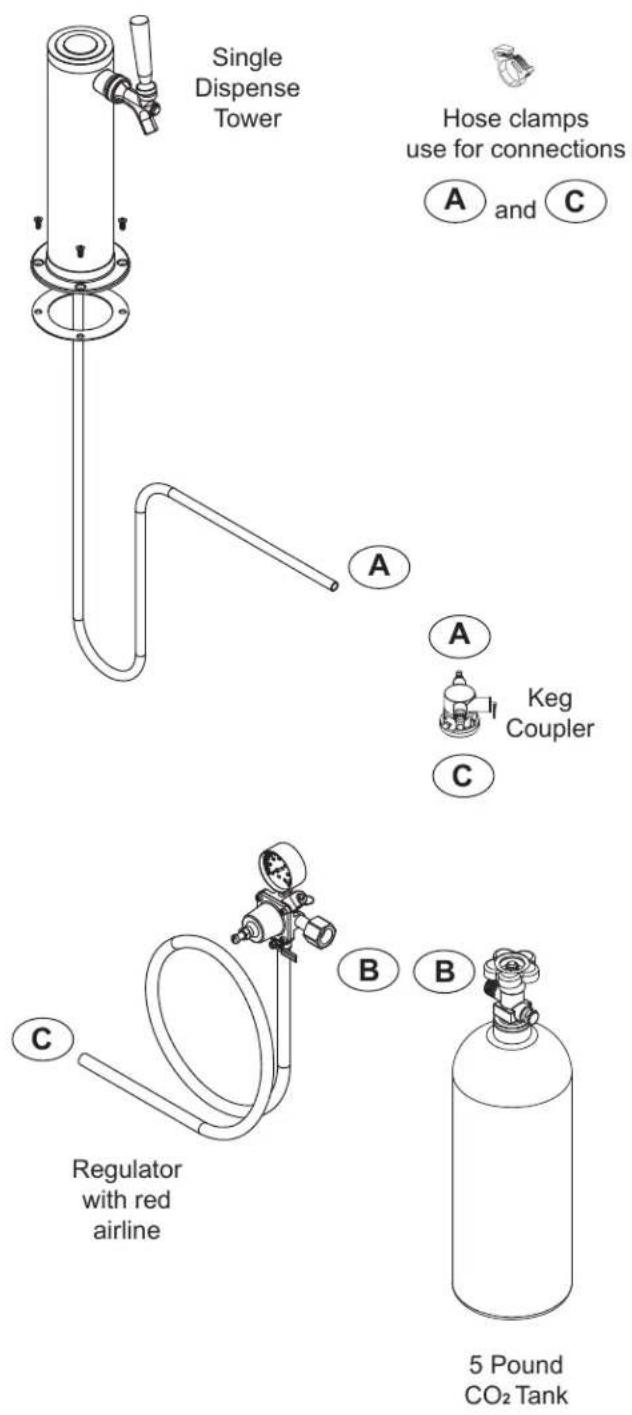
Single Dispense Tower Kit
Connect Ⓐ to Ⓐ ,etc......
Double Dispense Tower Kit
Connect Ⓐ to Ⓐ ,etc......
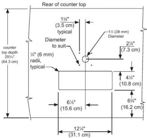

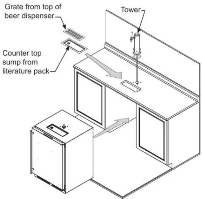
CAUTION
The cutout dimensions shown above are based on a 25516 " (64.3 cm) deep counter top. Your counter top may be different than this and require other front to back dimen-sioning. Refer to the product dimensions when determining the required dimensions.
-
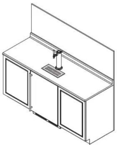
If you are installing your keg refrigerator under a counter you will need to drill 5 holes in the counter top to mount the tower. The first hole is a 1 12 " diameter hole located at the center of the tower for the beer line, locate approximately 13 12 " (34.3 cm) from the front edge of the counter top (based on a counter top depth of 25 516 "). Next drill the 4 tower mounting holes per the dimensions. The hole diameter is dependent on the counter top material and if screw anchors are required. The screws supplied are in the literature pack and are a #10 x 1" type AB stainless steel screw. Mark and cut the rectangular cutout for the drain sump. After the holes are drilled and the keg refrigerator is in place under the counter top feed the beer line through the tower gasket, the 1 12 " hole in the counter top and the hole in the top of the keg refrigerator. Mount the tower to the counter top with the 4 screws provided. Place the counter top drain sump, from the literature pack, in the rectangular hole with the radius cutout to the rear around the tower and place the grate in the sump.
-
Mount the regulator to the CO_2 tank (connection B). Note that the regulator has left hand threads and has to be turned counterclockwise to tighten. Tighten with the adjustable wrench or the 118 " open end wrench.
- Connect the red air line(s) from the regulator to the large air line fitting on the keg coupler with a large hose clamp (connection ⓒ).
- Connect the clear beer line from the tower to the small air line fitting on the keg coupler with a small hose clamp (connection A).
- Locate the CO_2 tank in the corner of the refrigerator and secure with the chain. Close the faucet handle on the tower.
natural_image
Isometric line drawing of a cabinet with three doors and a central shelf (no text or symbols)USING YOUR BEER DISPENSER
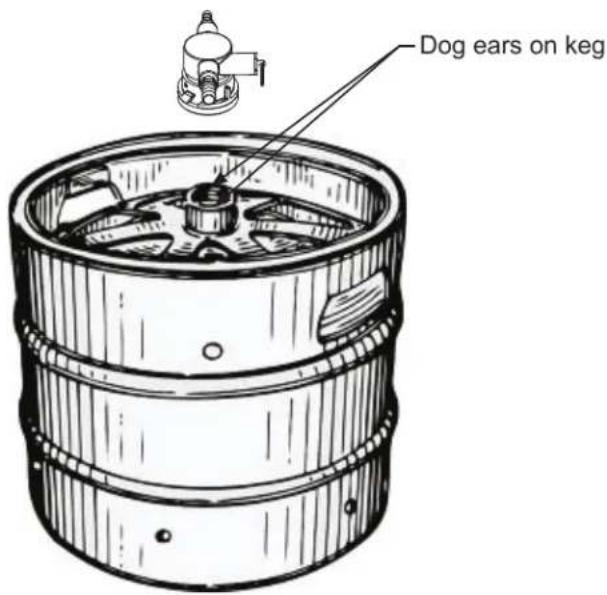
- Hooking up the keg coupler to the keg: Verify the coupler is in the "OFF" position. Align the lugs on the keg with the corresponding openings on the keg coupler and turn clockwise until the coupler stops (about 90°). Push down and twist the top of the coupler clockwise to allow gas to enter the keg.
Push faucet handle back toward tower to close the faucet
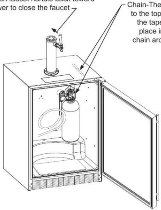
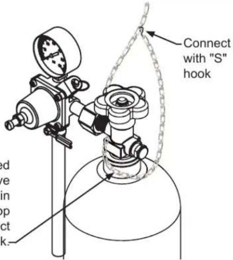
Chain-The chain is fastened and taped to the top of the interior liner. Remove the tape and secure the CO_2 tank in place in the back right corner. Loop chain around top of tank and connect with "S" hook.-
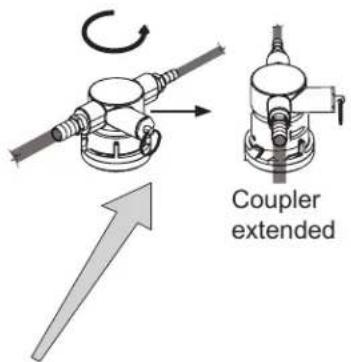
Rotate the top of the coupler counter clockwise to extend the coupler to the to the "OFF" position.
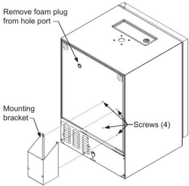
Optional CO₂ tank external mounting bracket:
The optional mounting bracket is designed to hold the 5# CO₂ cylinder that comes with the beer dispenser. Larger cylinders may be purchased from a third party and mounted externally. Use the hole port on the rear of the cabinet to run the CO₂ line to the keg.
Many options are available for mounting the CO_2 tank outside of the beer dispenser to gain additional cold storage space inside.
Secure the optional external mounting bracket on the back of the beer dispenser (this is ideal for mobile units) or mount within adjacent cabinetry (ideal for undercounter built-in units:
Mount the (4) screws (#10-32 x 3/4" flathead machine screws) provided with the bracket in the rear of the appliance. Do not completely tighten. Place the keyhole slots in the flanges of the bracket over the four screws and tighten them to secure the bracket to the back of the cabinet. The bracket can also be fastened to adjacent cabinetry using the provided #10 x 3/4" wood screws.
Mark the hole locations where required using a pencil and the slots in the mounting bracket. Drill appropriate pilot holes (depending on the material you are mounting to) and secure the bracket per the above instructions.
NOTE
The foam insulation plugs provided in the portholes are CRITICAL to proper functioning of the unit and preventing frost build up that can cause damage to the unit and/or refrigerator contents. ALWAYS reseal the CO2 line porthole with the provided insulation plugs once all lines have been properly installed.
NOTE
Consider the length of the red air line when choosing a place for the CO_2 tank. The red air line supplied is 4 feet (1.2 meters) long.
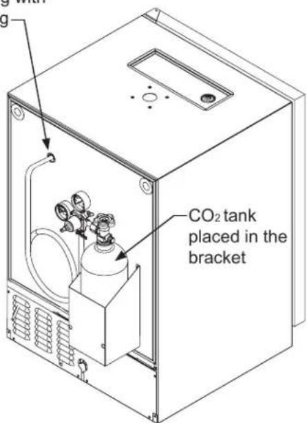
With the gauges mounted to the CO_2 tank place the tank in the mounting bracket.
Remove the foam plug from the hole port, and feed the red CO_2 line through the rear wall and out the coil cover on the inside of the cabinet. Connect the red CO_2 line to the keg coupler.
Reseal the hole in the back of the cabinet with the foam plug.

CAUTION
If the CO_2 tank is placed on the floor it must be secured in the upright position with a chain or other means to prevent it from being tipped over.
Reseal hole around tubing with the foam plug
CO₂ Regulator (Single Dispense Tower)
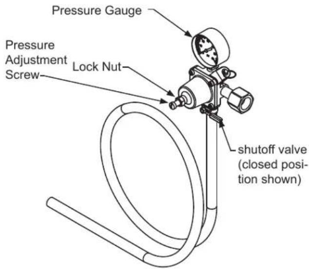
Your beer dispenser comes equipped with a 5 pound CO _2 tank and a single gauge regulator. The gauge reads the pressure being supplied to the beer keg. Follow the procedure below to adjust the pressure to 12 - 14 psi (0.8 to 1 bar) for lager beer or 9 - 12 psi (0.6 to 0.8 bar) for ale's.
To adjust the pressure (Single Gauge):
- Close the shutoff valve at the bottom of the regulator.
- Be sure the faucet handle is closed on the tower.
- Loosen the lock nut by turning ∩ counterclockwise using the 12 " open end wrench until loose, this will allow adjustment of the pressure adjustment screw.
- With the flat bladed screwdriver turn the adjustment screw clockwise to increase the pressure or counterclockwise to decrease the pressure.
- Open the shutoff valve on the bottom of the regula-tor. The gauge reading may drop but will return very quickly.
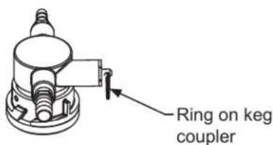
- Pull the ring on the keg coupler to allow the gas to flow momentarily.
- Make any fine adjustments if necessary with the adjust-ment screw.
- Tighten the locknut with the 12 " open end wrench by turning clockwise ∅.
(Regulator for Single Dispense Tower)
CO2 Regulator (Double Dispense Tower)
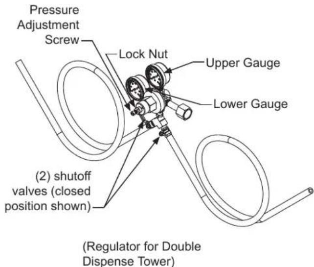
Your beer dispenser comes equipped with a 5 pound CO₂ tank and a dual gauge regulator. The lower gauge should be reading approximately 750 psi (52 bar) when the tank is properly filled and the tank is not in the refrigerator (at room temperature). The tank will read less when chilled. Use this lower gauge as an indicator of how much CO₂ you have left in the tank.
The upper gauge reads the pressure being supplied to the beer keg. Follow the procedure below to adjust the pressure to 12 - 14 psi (0.8 to 1 bar) for lager beer or 9 - 12 psi (0.6 to 0.8 bar) for ale's.
To adjust the pressure (Upper Gauge):
- Close the shutoff valves at the bottom of the regulator.
- Be sure the faucet handle is closed on the tower.
- Loosen the lock nut by turning ∘ counterclockwise using the 12 " open end wrench until loose, this will allow adjustment of the pressure adjustment screw.
- With the flat bladed screwdriver turn the adjustment screw clockwise to increase the pressure or counterclockwise to decrease the pressure.
- Open the shutoff valve on the bottom of the regula-tor. The gauge reading may drop but will return very quickly.
- Pull the ring on the keg coupler to allow the gas to flow momentarily.
- Make any fine adjustments if necessary with the adjust-ment screw.
- Tighten the locknut with the 12 " open end wrench by turning clockwise o.
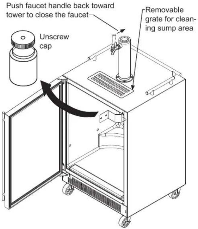
Drain kit (All Models): The drain kit is shipped in place and ready to use. To empty: Pull drain hose out of bottle cap, remove bottle from unit, unscrew cap and discard waste and rinse bottle. Reinstall bottle in unit.
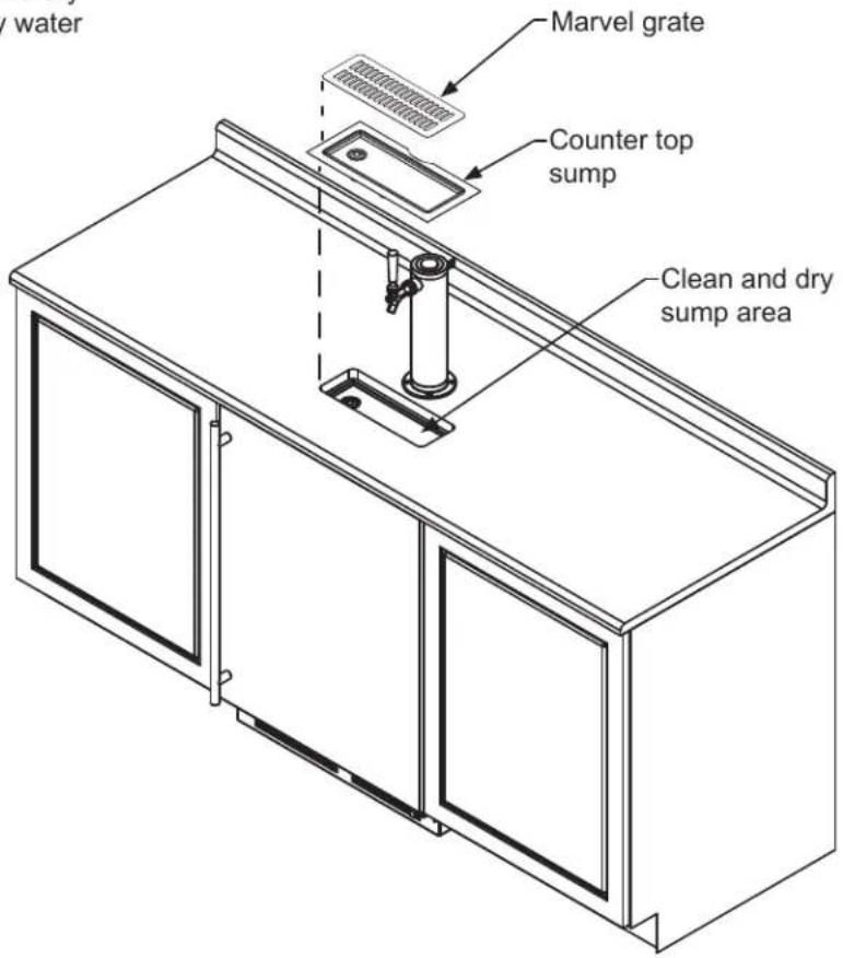
Cleaning the drain sump:
On a free standing beer dispenser remove the Marvel grate from in front of the tower, clean with soap and water and dry before reinstalling. Clean the sump area with soapy water and dry.
On a built in beer dispenser remove the Marvel grate and counter top sump, clean with soap and water and dry before reinstalling. Clean the sump area with soapy water and dry.
The following suggestions will minimize the cost of operating your refrigeration appliance.
- Do not install your appliance next to a hot appliance (cooker, dishwasher, etc.), heating air duct, or other heat sources.
- Install product out of direct sunlight.
- Ensure the front grille vents at front of appliance beneath door are not obstructed and kept clean to allow ventilation for the refrigeration system to expel heat.
- Plug your appliance into a dedicated power circuit. (Not shared with other appliances).
- When initially loading your new product, or whenever large quantities of warm contents are placed within refrigerated storage compartment, minimize door openings for the next 12 hours to allow contents to pull down to compartment set temperature.
- Maintaining a relatively full storage compartment will require less appliance run time than an empty compartment.
- Ensure door closing is not obstructed by contents stored in your appliance.
- Allow hot items to reach room temperature before placing in product.
- Minimize door openings and duration of door openings.
- Use the warmest temperature control set temperature that meets your personal preference and provides the proper storage for your stored contents.
- When on vacation or away from home for extended periods, set the appliance to warmest acceptable temperature for the stored contents.
-
Set the control to the "off" position if cleaning the appliance requires the door to be open for an extended period of time.
-
For wine storage products: When serving temperatures are not required, return the compartment(s) set temperature to the ideal red and white wine long term storage temperature of 13^ C / 55^ F.
If Service is Required:
- If the product is within the first year warranty period please contact your dealer or call Marvel Customer Service at 616.754.5601 for directions on how to obtain warranty coverage in your area.
- If the product is outside the first year warranty period, Marvel Customer Service can provide recommendations of service centers in your area. A listing of authorized service centers is also available at www.marvelrefrigeration.com under the service and support section.
- In all correspondence regarding service, be sure to give the service number, serial number, and proof of purchase.
- Try to have information or description of nature of the problem, how long the appliance has been running, the room temperature, and any additional information that may be helpful in quickly solving the problem.
- Table "B" is provided for recording pertinent information regarding your product for future reference.
| For Your Records | |
| Date of Purchase | |
| Dealer's name | |
| Dealer's Address | |
| Dealer's City | |
| Dealer's State | |
| Dealer's Zip Code | |
| Appliance Serial Number | |
| Appliance Service Number | |
| Date Warranty Card Sent (Must be within 10 days of purchase). | |
Table B
Ordering Replacement Parts
Parts may be ordered online at www.partsformarvel.com
Or contact:
www.marvelrefrigeration.com (Servicers choose "Login" for service account)
Phone Number: +1.616.754.5601
NOTICE
Use only genuine Marvel replacement parts. The use of non-Marvel parts can reduce performance, damage the unit, and void the warranty.
Warranty parts will be shipped at no charge after Marvel confirms warranty status. Please provide the model, serial number, part number and part description. Some parts will require color or voltage information.
If Marvel requires the return of original parts, we will inform you when the parts order is taken. This requirement will be noted on your packing list. A prepaid shipping label will be emailed to you. Please enclose a copy of the parts packing list and be sure the model and serial numbers are legible on the paperwork. Tag the part with the reported defect.
Customers and non-authorized servicers may order non-warranty parts at www.marvelrefrigeration.com.
Authorized servicers with a servicer login may order non-warranty parts at www.marvelrefrigeration.com.
Ordering Replacement Parts
Parts may be ordered online at partsformarvel.com
Or contact:
www.marvelrefrigeration.com (Servicers choose "Login" for service account).
Phone Number: (616) 754-5601
NOTICE
Use only genuine Marvel replacement parts. The use of non-Marvel parts can reduce performance, damage the unit, and void the warranty.
Warranty parts will be shipped at no charge after Marvel confirms warranty status. Please provide the model, serial number, part number and part description. Some parts will require color or voltage information.
Marvel requires the return of original parts, we will inform you when the parts order is taken. This requirement will be noted on your packing list. A prepaid shipping label will be emailed to you. Please enclose a copy of the parts packing list and be sure the model and serial numbers are legible on the paperwork. Tag the part with the reported defect.
Customers and non-authorized servicers may order non-warranty parts at www.partsformarvel.com. Authorized servicers with a servicer login may order non-warranty parts at www.marvelrefrigeration.com.
R-600A Specifications & Handling
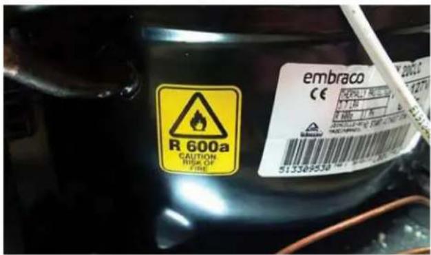
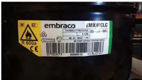
Flammability warnings for a pure-iso-butane refrigerant.
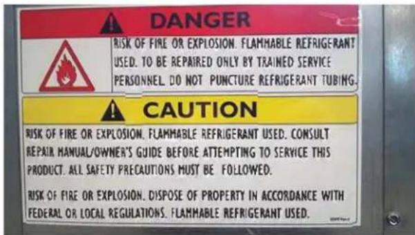
Tension must leave all weeks, now around last meeting yesterday.
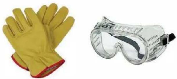
Gloves and Eye Protection must be used.
natural_image
Two types of protective gear: yellow hand gloves and clear safety goggles (no text or symbols visible)R-600a is considered non-toxic, but is flammable when mixed with air.
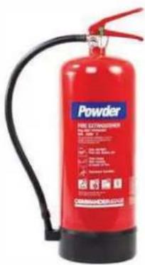
Keep a dry powder type fire extinguisher in the work area.
natural_image
Red fire extinguisher with attached hose and black handle (no visible text or symbols)R-600a is heavier than air, do not allow any leakage/migration to low areas such as basements and stairs.
Never use a torch on a fully charged refrigeration system.
Never substitute Marvel OEM replacement parts or methods of construction.
R-600a must be stored and transported in approved containers.
WARNING
Only skilled and well trained service technicians permitted to service R-600a equipped products.
All tools and equipment must be approved for use with R-600a refrigerant.
Local, state and federal laws, standards must be observed along with proper certification and licensing.
Ventilation is required during servicing.
No conversions to R-600a from any other refrigerants. OEM R-600a equipped unit only.
Service area must be free of ignition sources.
No smoking is allowed in the service area.
All replacement electrical components must be OEM and installed properly (sealed and covered).
If the evaporator is cold prior to service, it must be thawed prior to service.
When using a vacuum pump, start pump before opening refrigeration system.
Vacuum pump and recovery equipment should be at least 10 feet from the work area.
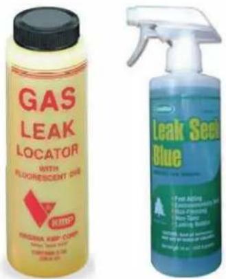
It is recommended that a simple LPG gas detector is on site during service.
Ensure that all R-600a is removed from the system prior to brazing any part of the sealed system.
Only a clean, dry leak free system should be charged with R-600a.
R-600A SPECIFICATIONS/LABELING
R-600a equipped products are labeled (both the unit and the compressor).
R-600a is colorless and odorless.
R-600a is considered non-toxic, but is flammable when mixed with air.
Do not remove or alter any R-600a labeling on the product.
Use only a refrigerant grade R-600a from a properly labeled container.
RECOVERING/RECLAIMING R-600A
(R-600a has been exempted from recovery/reclaiming requirements by the US EPA)
Recovery/Reclaiming equipment must be approved for use with R-600a.
Ensure the evaporator is at room temperature prior to recovery/reclaiming R-600a.
Use a common piercing pliers or piercing valve to remove R-600a from the compressor process tube. (Note: Piercing devices must not be left on the system and must be replaced with a Schrader type valve.)
Evacuate/reclaim via the piecing pliers to ensure the system is empty of R-600a before any system work is performed.
The recovery cylinder must be evacuated (no air inside) prior to accepting R-600a.
The recovery cylinder must not be filled more than 45% safe fill level and refrigerants must not be mixed.
The recovery cylinder must be clearly marked with R-600a and Flammable Warning labels.
Ensure proper ventilation during recovery/reclaiming of R-600a.
Start vacuum pump/recovery pump prior to piercing the compressor process tube.
Follow recovery/reclaim OEM instructions for the specific equipment used.
SYSTEM REPAIR
Ensure no residual R-600a refrigerant is left within the system prior to repair (simple venting is not sufficient).
Evacuate and charge with dry nitrogen for leak checks.
Repair leaks or replace system parts as required.
When re-brazing, the system must be purged with dry nitrogen and at least one access point open to the atmosphere.
When re-brazing, proper ventilation is required along with constant monitoring for the presence of R600a refrigerant.
The filter dryer must be replaced any time the sealed system is serviced.
No system should be open to the atmosphere for longer than 15 minutes to avoid moisture migration into the system components.
LEAK DETECTION
After removal of the R-600a, the unit can be charged with dry nitrogen or helium.
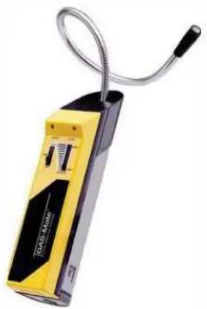
Electronic leak detection or soap solution can be used to check for nitrogen/helium leaks.
natural_image
Yellow and black handheld device with coiled cable, no visible text or symbolsNever use a halide torch or lighted match to check the system for leaks at any time.
The high side of the refrigeration system (compressor discharge to outlet of drier) must be leak tested with the compressor running.
The low side of the refrigeration system (evaporator, compressor and suction line) must be leak tested with the compressor off (equalized pressure).
RECHARGING
No air is ever to be allowed inside the refrigeration system (R-600a refrigerant or dry nitrogen only).
Never use a torch on a fully charged refrigeration system.
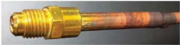
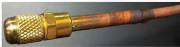
Install a Schrader Type access port on the compressor process stub.
natural_image
Close-up of a brass-colored mechanical pipe fitting with threaded ends (no text or symbols visible)Evacuate the system to 100 microns prior to charging.
Weigh in the R-600a charge using a refrigerant scale. (run compressor an extra two minutes to clear the charging hoses).
Seal the Schrader Type access port, a proper cap and seal must be used to close the system.
natural_image
Close-up of a brass and gold-colored connector with threaded ends (no visible text or symbols)SUMMARY
Safely handling R-600a requires proper procedures and training.
R-600a approved service tools must be used.
R-600a labeling must not be removed or altered.
Proper ventilation during service is required.
Never apply a torch to a charged R-600a refrigeration system.
Use OEM replacement service parts and do not alter the construction of the unit.
System Diagnosis Guide
| System Condition | Suction Pressure | Suction Line | Compressor Discharge | Condenser | Capillary Tube | Evaporator | Wattage |
| Normal | Normal | Slightly below room temperature | Very hot | Very hot | Warm | Cold | Normal |
| Overcharge | Higher than normal | Very cold may frost heavily | Slightly warm to hot | Hot to warm | Cool | Cold | Higher than normal |
| Undercharge | Lower than normal | Warm- near room temperature | Hot | Warm | Warm | Extremely cold near inlet - Outlet below room temperature | Lower than normal |
| Partial Restriction | Somewhat lower than normal vacuum | Warm- near room temperature | Very hot | Top passes warm - Lower passes cool (near room temperature) due to liquid | Room temperature (cool) or colder | Extremely cold near inlet - Outlet below room temperature backing up | Lower than normal |
| Complete Restriction | In deep vacuum | Room temperature (cool) | Room temperature (cool) | Room temperature (cool) | Room temperature (cool) | No refrigeration | Lower than normal |
| No Gas | 0 PSIG to 25" | Room temperature (cool) | Cool to hot | Room temperature (cool) | Room temperature (cool) | No refrigeration | Lower than normal |
Marvel Refrigeration (Marvel) Limited Warranty
ONE YEAR LIMITED PARTS & LABOR WARRANTY
For one year from the date of original purchase, this warranty covers all parts and labor to repair or replace any part of the product that proves to be defective in materials or workmanship. For products installed and used for normal residential use, material cosmetic defects are included in this warranty, with coverage limited to 60 days from the date of original purchase. All service provided by Marvel under the above warranty must be performed by a Marvel factory authorized servicer, unless otherwise specified by Marvel. Service provided during normal business hours.
TWO YEAR LIMITED PARTS & LABOR WARRANTY (MARVEL PROFESSIONAL PRODUCTS)
For two years from the date of original purchase, this warranty covers all parts and labor to repair or replace any part of the product that proves to be defective in materials or workmanship. For products installed and used for normal residential use, material cosmetic defects are included in this warranty, with coverage limited to 60 days from the date of original purchase. All service provided by Marvel under the above warranty must be performed by a Marvel factory authorized servicer, unless otherwise specified by Marvel. Service provided during normal business hours.
AVAILABLE THIRD YEAR LIMITED WARRANTY (MARVEL PROFESSIONAL PRODUCTS)
For designated Marvel Professional product, Marvel offers a one year extension of the two year warranty coverage from the date of purchase, free of charge. To take advantage of this third year warranty, you must register your product with Marvel within 60 days from the date of purchase at marvelrefrigeration.com and provide proof of purchase.
LIMITED FIVE YEAR SEALED SYSTEM WARRANTY
For five years from the date of original purchase, Marvel will repair or replace the following parts, labor not included, that prove to be defective in materials or workmanship: compressor, condenser, evaporator, drier, and all connecting tubing. All service provided by Marvel under the above warranty must be performed by a Marvel factory authorized servicer, unless otherwise specified by Marvel. Service provided during normal business hours.
WARRANTY TERMS
These warranties apply only to products installed in any one of the fifty states of the United States, the District of Columbia, or the ten provinces of Canada. The warranties do not cover any parts or labor to correct any defect caused by negligence, accident or improper use, maintenance, installation, service, repair, acts of God, fire, flood or other natural disasters. The product must be installed, operated, and maintained in accordance with the Marvel User Guide.
The remedies described above for each warranty are the only ones that Marvel will provide, either under these warranties or under any warranty arising by operation of law. Marvel will not be responsible for any consequential or incidental damages arising from the breach of these warranties or any other warranty, whether express, implied, or statutory. Some states do not allow the exclusion or limitation of incidental or consequential damages, so the above limitation or exclusion may not apply to you. These warranties give you specific legal rights, and you may also have other rights which vary from state to state.
Any warranty that may be implied in connection with your purchase or use of the product, including any warranty of merchantability or any warranty fit for a particular purpose is limited to the duration of these warranties, and only extends to five years in duration for the parts described in the section related to the five year limited warranty above. Some states do not allow limitations on how long an implied warranty lasts, so the above limitations may not apply to you.
• The warranties only apply to the original purchaser and are non-transferable.
• These warranties cover products installed and used for normal residential use only.
• The warranties apply to units operated outside only if designed for outdoor use by model and serial number.
• Replacement water filters, light bulbs, and other consumable parts are not covered by these warranties.
The start of Marvel's obligation is limited to four years after the shipment date from Marvel.
• In-home instruction on how to use your product is not covered by these warranties.
• Food, beverage, and medicine loss are not covered by these warranties.
• If the product is located in an area where Marvel factory authorized service is not available, you may be responsible for a trip charge or you may be required to bring the product to a Marvel factory authorized service location at your own cost and expense.
- Units purchased after use as floor displays, and/or certified reconditioned units, are covered by the limited one year warranty only and no coverage is provided for cosmetic defects.
• Signal issues related to Wi-Fi connectivity are not covered by these warranties.
For parts and service assistance, or to find Marvel factory authorized service near you, contact Marvel Refrigeration:
MarvelRefrigeration.com • techsupport@MarvelRefrigeration.com • +616.754.5601
1260 E. Van Deinse St., Greenville, MI 48838
- Important Safety Instructions
- WARNING
- CAUTION
- NOTE
- Tip: Click on any section below to jump directly there
- Safety
- Installation
- Operating Instructions
- Service
- EXCESSIVE WEIGHT HAZARD
- Remove Interior Packaging
- Important
- Note to Customer
- WARNING - Help Prevent Tragedies
- Electrical Connection
- Electrical Shock Hazard
- Shelving
- Tools required for installation:
- Tap Equipment and Assembly
- USING YOUR BEER DISPENSER
- Optional CO₂ tank external mounting bracket:
- Secure the optional external mounting bracket on the back of the beer dispenser (this is ideal for mobile units) or mount within adjacent cabinetry (ideal for undercounter built-in units:
- CO₂ Regulator (Single Dispense Tower)
- To adjust the pressure (Single Gauge):
- CO2 Regulator (Double Dispense Tower)
- To adjust the pressure (Upper Gauge):
- Cleaning the drain sump:
- The following suggestions will minimize the cost of operating your refrigeration appliance.
- If Service is Required:
- Ordering Replacement Parts
- Parts may be ordered online at www.partsformarvel.com
- NOTICE
- Parts may be ordered online at partsformarvel.com
- R-600A Specifications & Handling
- class
- R-600A SPECIFICATIONS/LABELING
- RECOVERING/RECLAIMING R-600A
- SYSTEM REPAIR
- LEAK DETECTION
- RECHARGING
- SUMMARY
- System Diagnosis Guide
- Marvel Refrigeration (Marvel) Limited Warranty
- ONE YEAR LIMITED PARTS & LABOR WARRANTY
- TWO YEAR LIMITED PARTS & LABOR WARRANTY (MARVEL PROFESSIONAL PRODUCTS)
- AVAILABLE THIRD YEAR LIMITED WARRANTY (MARVEL PROFESSIONAL PRODUCTS)
- LIMITED FIVE YEAR SEALED SYSTEM WARRANTY
- WARRANTY TERMS
Brand : Marvel
Model : MOKR124SS31A
Category : Beer dispenser