
UBCD396XT - Voice recorder UNIDEN - Free user manual and instructions
Find the device manual for free UBCD396XT UNIDEN in PDF.


| Brand | Uniden |
| Model | UBCD396XT |
| Product Type | Digital trunking scanner with voice recording |
| Dimensions | 2.5 x 1.5 x 6 inches (approx.) |
| Weight | 10 oz (including batteries) |
| Power Source | 4x AA batteries or DC adapter (optional) |
| Frequency Range | 25-1300 MHz (excluding cellular) |
| Modes Supported | Analog, digital (P25 Phase I/II), trunking |
| Recording Capacity | Up to 4GB microSD card (not included) |
| Display | Backlit LCD, multi-line |
| Audio Output | Built-in speaker, headphone jack |
| Main Functions | Scanning, trunk tracking, recording, close call, fire/police/ems |
| Programming Method | Keypad or PC software via USB |
| Maintenance | Clean with soft dry cloth; avoid liquids |
| Safety | Keep away from moisture; use only specified batteries |
| Spare Parts & Reparability | Contact Uniden support or authorized service centers |
| General Information | User manual download available at notice-facile.com |
Frequently Asked Questions - UBCD396XT UNIDEN
User questions about UBCD396XT UNIDEN
0 question about this device. Answer the ones you know or ask your own.
Ask a new question about this device
Download the instructions for your Voice recorder in PDF format for free! Find your manual UBCD396XT - UNIDEN and take your electronic device back in hand. On this page are published all the documents necessary for the use of your device. UBCD396XT by UNIDEN.
USER MANUAL UBCD396XT UNIDEN
UBCD396XT OWNER'S MANUAL
NOTE ON COLOURED TEXT:
- Sections within this document are numbered to help you navigate the content.
- Text within the sections which are coloured blue indicate more information about the indicated text may be available as a section of the same name. Refer to the table of contents to navigate to these sections.
- Text within the sections which are underlined and coloured blue (not including the section headers) may be hyperlinked to that specific section or website.
Table of Contents
1. GENERAL PRECAUTIONS .... 1
EARPHONE WARNING .... 1
LIQUID EXPOSURE WARNING.... 1
POWER DISCONNECTION CAUTION .... 1
2. SETTING UP THE HARDWARE 2
WHAT'S INCLUDED INSIDE THE BOX? 2
INSTALL THE BATTERIES 3
CONNECT THE ANTENNA....3
ATTACH THE BELT CLIP 4
3. CONNECTING A GPS RECEIVER.... 5
COMPATIBLE GPS RECEIVERS 5
CONFIGURING YOUR SCANNER....5
CONNECTING THE RECEIVER.... 5
TROUBLESHOOTING 6
4. USING PRELOADED SYSTEMS....7
PRELOADED SYSTEMS 7
6. KEYS AND THEIR FUNCTIONS .... 11
KEY OVERVIEW....11
Create at least 1 channel group.... 20
Create at least 1 channel in each group.... 20
10. EDACS SCAT SYSTEMS 24
PROGRAMMING AN EDACS SCAT SYSTEM 24
Create a system 24
Create a site 25
Create at least 1 frequency....25
11. EDACS TRUNKED SYSTEMS 28
PROGRAMMING AN EDACS SYSTEM....28
Create a system 28
Create at least 1 site 29
Create at least 1 frequency in each site.... 30
PROGRAMMING A SYSTEM FOR SCANNING 31
Create at least 1 channel group.... 31
Create at least 1 channel in each group.... 31
12. LTR TRUNKED SYSTEMS.... 36
PROGRAMMING AN LTR SYSTEM 36
Create a system 36
Create at least 1 site 37
Create at least 1 frequency in each site.... 38
PROGRAMMING A SYSTEM FOR SCANNING 38
Create a channel group.... 39
Create a channel in each group.... 39
13. MOTOROLA TRUNKED SYSTEMS 42
PROGRAMMING A MOTOROLA SYSTEM 42
Create a system 42
UBCD396XT
Create at least 1 site 43
Create at least 1 frequency in each site.... 44
PROGRAMMING A SYSTEM FOR SCANNING 44
Create a channel group.... 45
Create a channel.... 45
- MOTOROLA FLEET MAPS....50
PRESET FLEET MAPS 50
CUSTOM FLEET MAPS 50
HOW FLEET MAPS WORK.... 51
Blocks 51
Size Codes 52
- STANDARD P25 TRUNKED SYSTEMS.... 53
PROGRAMMING A P25 SYSTEM.... 53
Create a system 53
Create at least 1 site 54
Create at least 1 frequency in each site....54
PROGRAMMING A SYSTEM FOR SCANNING 55
Create a channel group.... 55
Create a channel in a group.... 56
- SINGLE-FREQUENCY P25 TRUNKED SYSTEMS.... 59
PROGRAMMING A SINGLE-FREQUENCY P25 SYSTEM.... 59
Create a system 59
Create exactly 1 site....60
PROGRAMMING A SYSTEM FOR SCANNING 60
Create a channel group.... 61
Create a channel.... 61
Trunked system basics.... 64
How a trunked system works 64
A real life example.... 65
- DECIPHERING TRUNKED SYSTEMS 66
BEFORE YOU PROGRAM A TRUNKED SYSTEM 66
System Type.... 66
System Voice.... 67
UBCD396XT
System Frequencies.... 68
Talk Group IDs (Channels).... 68
19. LOCATION-BASED SCANNING 69
THE GEOPOLITICAL APPROACH 70
THE ANTENNA-CENTRIC APPROACH....73
COMBINING FOR EFFICIENCY....74
20. NUMBER TAGS 76
PROGRAMMING NUMBER TAGS 76
Assigning an SNT.... 76
Assigning a CHNT.... 77
USING NUMBER TAGS....78
21. QUICK KEYS....79
PROGRAMMING QUICK KEYS 79
Assigning an SQK 79
Assigning a GQK.... 80
USING QUICK KEYS 80
To use SQK 0 through 9....81
To use SQK 10 through 99....81
To use a GQK.... 81
22. SEARCH KEYS....82
PROGRAMMING SEARCH KEYS 82
USING SEARCH KEYS 82
23. PROGRAMMING LOCATIONS....83
PROGRAMMING A LOCATION FOR A SITE....83
PROGRAMMING A LOCATION FOR A CHANNEL GROUP....83
PROGRAMMING GENERAL LOCATIONS 83
To create a new location.... 84
For Dangerous Xing and Dangerous Roads only.... 85
Edit an existing location 85
24. SETTING ALERTS....86
25. USING QUICK KEYS, STARTUP KEYS, AND SEARCH KEYS.... 88
QUICK KEYS....88
STARTUP KEYS 88
SEARCH KEYS 88
26. TONE OUT MODE....89
UBCD396XT
CONFIGURING TONE OUT CHANNELS 89
USING TONE-OUT MODE 89
KEY OPERATION IN TONE OUT MODE 90
27. CLOSE CALL MODE 92
KEY OPERATION IN CLOSE CALL ONLY MODE.... 92
28. BAND SCOPE MODE....95
TO TURN ON BAND SCOPE MODE: 95
KEY OPERATION IN BAND SCOPE MODE 96
29. GPS MODE 99
SEE ALSO 99
READING THE DISPLAY IN GPS MODE 100
Main GPS display.... 100
Location alert display.... 100
Location review display.... 101
KEY OPERATION IN GPS MODE 102
30. PROGRAM SYSTEM....105
EDIT NAME 105
EDIT SYS OPTION.... 105
EDIT SITE....105
EDIT GROUP....106
COPY SYSTEM 106
DELETE SYSTEM 106
NEW SYSTEM 106
31. EDIT SYS OPTION.... 107
GLOBAL SYSTEM OPTIONS 107
Set Number Tag 107
Set Delay Time 107
Set Audio AGC.... 107
CONVENTIONAL SYSTEM OPTIONS.... 107
Set Quick Key.... 107
Set Startup Key.... 108
Set Lockout 108
Set Hold Time.... 108
P25 Waiting Time.... 108
TRUNKED SYSTEM OPTIONS 109
ID Scan/Search 109
UBCD396XT
Priority ID Scan.... 109
Emergency Alert.... 109
Set ID Format (DEC/HEX) or (AFS/DEC) 109
Rvw ID:Srch L/O.... 110
Clr All L/O IDs.... 110
MOTOROLA SYSTEM OPTIONS.... 110
Edit Fleet Map.... 110
Set Status Bit.... 110
Set End Code 110
P25 SYSTEM OPTIONS 110
P25 NAC Option.... 111
- EDIT GROUP.... 112
OPTIONS AVAILABLE FOR ALL GROUPS: 112
Edit Name.... 112
Set Quick Key 112
Edit Channel.... 112
Set LocationInfo.... 112
Set Lockout 112
Delete Group.... 113
New Group 113
- SET LOCATIONINFO.... 114
SET LATITUDE AND SET LONGITUDE 114
SET RANGE 114
SET GPS ENABLE 114
- EDIT CHANNEL.... 116
EDIT FREQUENCY (CONVENTIONAL SYSTEMS) 116
EDIT TALK GROUP ID (TRUNKED SYSTEMS).... 116
OPTIONS AVAILABLE FOR ALL CHANNELS: 116
Edit Name.... 116
Set Audio Type.... 116
Set Number Tag 116
Set Modulation 117
Set Attenuator.... 117
Set Priority.... 117
Set Alert 117
Set Lockout 117
Volume Offset 118
Copy Channel.... 118
UBCD396XT
Delete Channel 118
New Channel 118
ANALOG CHANNEL OPTIONS.... 118
Set CTCSS/DCS.... 118
DIGITAL CHANNEL OPTIONS.... 119
P25 NAC Option.... 119
35. EDIT SITE 120
OPTIONS AVAILABLE FOR ALL SITES: 120
Edit Name.... 120
Set Quick Key 120
Set Startup Key 120
Set Frequencies 121
Set Modulation 121
Set Attenuator 121
Set Lockout 121
Set Hold Time.... 121
Set LocationInfo.... 121
Delete Site 122
New Site 122
OPTIONS AVAILABLE FOR MOTOROLA SYSTEMS 122
OPTIONS AVAILABLE FOR P25 SYSTEMS.... 122
Edit Band Plan (P25) 122
OPTIONS AVAILABLE FOR EDACS SYSTEMS 123
Set Site Type.... 123
Volume Offset (EDACS SCAT Only).... 123
36. SET FREQUENCIES.... 124
Edit Frequency 124
Set Lockout 124
Delete Frequency.... 124
New Frequency.... 124
LTR AND EDACS SYSTEM OPTIONS 124
LCN (Logical Channel Number).... 125
EDACS SCAT SYSTEM OPTIONS.... 125
Set Number Tag 125
Volume Offset 125
37. SCAN MODE.... 126
SCANNING VS. SEARCHING.... 126
Scanning trunked systems.... 126
UBCD396XT
Searching trunked systems 126
DEFAULT SCAN MODE 126
LOCKED ITEMS.... 127
KEY OPERATION IN SCAN MODE.... 127
Special keys.... 127
Keypad controls 128
KEY OPERATION IN SEARCH MODE.... 131
Special keys.... 131
Keypad controls 131
38. HOLD MODE.... 134
READING THE DISPLAYS IN HOLD MODE 136
Conventional system display.... 136
Trunked system display.... 137
Service search with scan hold display.... 138
39. EDIT TALK GROUP ID 139
MOTOROLA TYPE I SYSTEMS.... 139
MOTOROLA TYPE II SYSTEMS 139
P25 SINGLE FREQUENCY SYSTEMS OR STANDARD SYSTEM TRUNK SITE.... 139
EDACS WIDE OR NARROW SYSTEMS 139
AFS format.... 139
I-CALL CHANNEL (MOTOROLA, P25 OR EDACS) 140
LTR SYSTEMS 140
40. EDIT BAND PLAN 141
CREATING A CUSTOM BAND PLAN.... 141
Band plan number.... 141
Set Base Freq.... 141
Set Offset.... 141
Set Spacing 141
41. CALCULATING UPPER BASE FREQUENCIES.... 142
Custom Frequency Table.... 142
42. CLOSE CALL.... 145
CLOSE CALL ONLY 145
CC AUTO STORE 145
HITS WITH SCAN 145
Set Quick Key 145
UBCD396XT
Set Number Tag 145
Set Lockout 146
Set Hold Time.... 146
SET CC MODE.... 146
SET CC OVERRIDE 146
SET CC ALERT 146
SET CC BANDS.... 147
43. PRIORITY SCAN.... 149
PRIORITY SCAN MENU 149
Set Priority.... 149
Set Interval 149
MaxCHs/Pri-Scan 150
44. PROGRAM LOCATION.... 151
POI 151
Edit Name 151
Set Type 151
Set Alert 151
Set Location Info.... 152
Set Range.... 152
Set Lockout 152
Delete Location 153
New Location 153
Search with Scan.... 158
CUSTOM SEARCH 158
EDIT CUSTOM 158
Edit Name 158
Edit Srch Limit.... 158
Set Delay Time 159
Set Modulation 159
Set Attenuator 159
Set Step 159
Set C-Ch Only.... 159
Set Audio AGC.... 160
P25 Waiting Time.... 160
Search with Scan 160
SEARCH AND STORE 160
SET SEARCH KEY 161
- SEARCH WITH SCAN 162
SET QUICK KEY 162
SET STARTUP KEY.... 162
SET NUMBER TAG 162
SET LOCKOUT 162
SET HOLD TIME 162
-
SET ALERT TONE.... 163
-
SRCH/CLOCALL OPT....164
FREQ LOCKOUTS....164
BROADCAST SCREEN....164
Set All Band On.... 164
Set All Band Off.... 164
Set Each Band 164
Program Band.... 165
TONE/CODE SEARCH 165
REPEATER FIND 165
MAX AUTO STORE 165
SET DELAY TIME.... 165
SET ATTENUATOR 166
UBCD396XT
SET AUDIO AGC 166
P25 WAITING TIME.... 166
50. STARTUP KEYS.... 167
ASSIGNING STARTUP KEYS 167
USING STARTUP KEYS 168
51. TONE A AND TONE B SETTINGS.... 170
52. TONE-OUT FOR.... 172
TONE-OUT STANDBY....172
TONE-OUT SETUP 172
Edit Name 172
Set Frequencies 172
Set Delay Time 172
Set Alert 172
Set Audio AGC 173
TONE-OUT SEARCH.... 173
53. KEY SAFE MODE 174
TO TURN KEY SAFE MODE ON (OR OFF).... 174
54. SETTINGS 177
SET BACKLIGHT 177
Set Mode.... 177
Set Dimmer 177
Set Color.... 177
ADJUST KEY BEEP 177
BATTERY OPTION....177
Set Battery Save.... 177
Set Charge Time.... 178
ADJUST AUDIO AGC 178
ADJUST CONTRAST 178
SET C-CH OUTPUT 179
SET GPS FORMAT 179
Set Pos Format 179
Set Time Format.... 179
Set Time Zone 179
Set Unit 179
SET SERIAL PORT 179
BAND DEFAULTS.... 180
Set Modulation 180
UBCD396XT
Set Step 180
P25 LP FILTER 180
DISPLAY UNIT ID 180
SEE SCANNER INFO.... 181
% Memory Used.... 181
Firmware Version.... 181
-
WIRED CLONE 182
-
UBCD396XT SPECIFICATIONS.... 183
GENERAL.... 183
FREQUENCY RANGE 185
SPECIAL FUNCTIONS.... 185
Band Scope Function.... 185
Two-Tone-Sequential 185
SUPPORTED TRUNKING SYSTEMS 185
DYNAMIC MEMORY ALLOCATION CAPACITY.... 186
HETERODYNE SYSTEM 186
CTCSS AND DCS TONES....186
- WARRANTY.... 188
UBCD396XT
1. General Precautions
Before you use this scanner, please read and observe the following:
Earphone Warning
You can use an optional 32Ω stereo headset or earphone with your scanner. Use of an incorrect earphone or headset might be potentially hazardous to your hearing. The output of the phone jack is monaural, but you will hear it in both headphones of a stereo headset.
Set the volume to a comfortable audio level coming from the speaker before plugging in the earphone or headset. Otherwise, you might experience some discomfort or possible hearing damage if the volume suddenly becomes too loud because of the volume control or squelch control setting. This might be particularly true of the type of earphone that is placed in the ear canal.
Liquid Exposure Warning
Uniden does not represent this unit to be waterproof. To reduce the risk of fire or electrical shock, do not expose this unit to rain or moisture!
Power Disconnection Caution
Important: Always turn the scanner off before disconnecting external power. Some settings are saved only as the scanner is powering down.
2. Setting up the hardware
What's included inside the box?
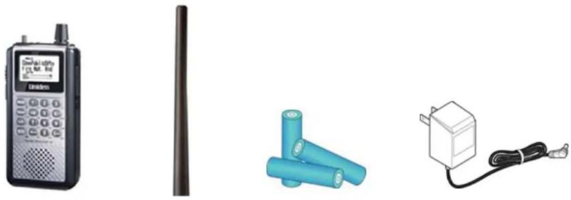
- UBCD396XT
- SMA antenna
• NiMH rechargeable batteries (3)
- AC adaptor
natural_image
Illustration of a USB cable with two connectors (no text or symbols)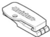

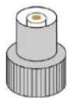
• SMA-to-BNC adaptor for external antennas
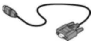
• Data transfer cable
- Beltclip
- Wrist strap
- Owner's Manual CD-ROM
- Quick Start Guide Sheet
The cover for the battery compartment might be packed separately, also.
Note! If any of these pieces are missing or damaged, contact your place of purchase immediately. Never used damaged equipment!
UBCD396XT
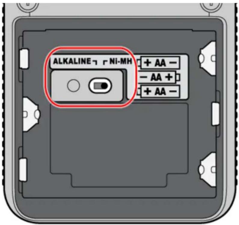
Install the batteries
Your scanner can use either regular alkaline batteries or rechargeable nickel-metal hydride (NiMH) batteries.
The batteries that came with your scanner are rechargeable NiMH.
To install the batteries:
-
Remove the cover from the battery compartment.
-
Make sure that the charge switch is set to the correct battery type:
- Use the Alkaline setting for any regular or nonrechargeable battery
• Use the NiMH setting for any rechargeable battery
-
Make sure the polarity (plus and minus) of each battery matches the diagram inside the compartment.
-
Replace the battery compartment cover.
Connect the antenna
natural_image
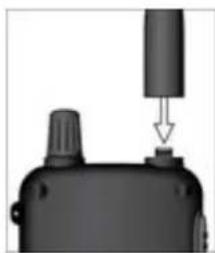
Close-up of a black electronic device with a cylindrical component and a small base, no visible text or symbolsTo connect the antenna, just screw it onto the SMA connector at the top of the scanner.
If you want to use an external antenna, attach the included SMA/BNC adapter to the scanner's SMA connector.
Then, connect your external antenna to the BNC connector.
UBCD396XT
Note! Always use 50- or 75-ohm, RG-58, or RG-8, coaxial cable and the supplied SMA/BNC adapter to connect an outdoor antenna. If the antenna is over 50 feet from the scanner, use RG- 8 low-loss dielectric coaxial cable. Cable loss increases with higher frequency.
Attach the belt clip
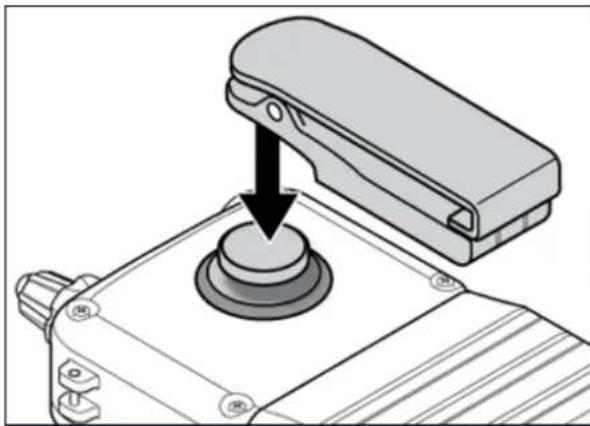
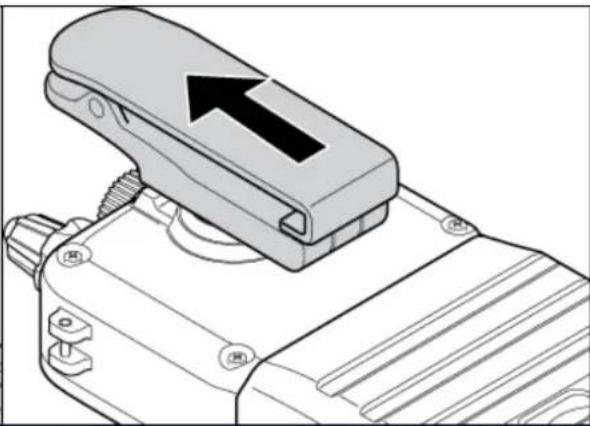
Hold the belt clip with the logo facing you and the hinge facing the top of the scanner. Place the clip over the post, and slide the belt clip straight up until you hear it click into place.
natural_image
Mechanical assembly diagram showing a lever pressing a circular component (no text or symbols)Place the clip over the post.
natural_image
Technical line drawing of a mechanical clamp or connector component with an arrow indicating direction (no text or symbols present)Slide the clip up into place
To remove the belt clip
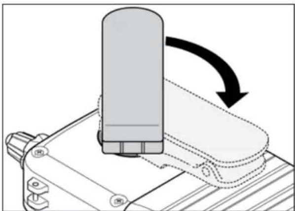
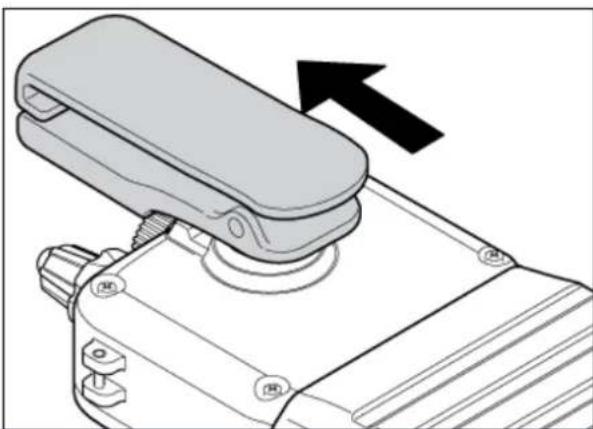
Rotate the scanner so the scanner is bottom-side up. Then slide the scanner straight up until it comes free from the belt clip.
natural_image
Mechanical component diagram showing a cylindrical component being inserted into a housing, with an arrow indicating rotation (no text or symbols present)Rotate the scanner 180 degrees.
natural_image
Technical line drawing of a mechanical device with a lever and adjustment knob (no text or symbols)Slide the scanner up and off the belt
UBCD396XT
3. Connecting a GPS receiver
A third party GPS receiver is required to utilise the scanner's location based features.
Compatible GPS receivers
You can connect your scanner to any GPS receiver that meets the following criteria:
- Outputs NMEA-0183 v3.01-compliant location data
- Outputs both the Global Positioning System Fix (GGA) and Recommended Minimum Specific GNSS (RMC) data sentences
- Provides a serial data (RS-232) connection
Configuring your scanner
- Go to the Settings menu and select Set Serial Port.
- Select 4800 bps for the baud rate.
Connecting the receiver
- Connect your GPS receiver to a null modem adapter or cable.
- Connect the data transfer cable that was supplied with your scanner to the null modem.
UBCD396XT
-
*The data transfer cable has a DE-9 socket (female) connector. To connect to the data transfer cable, you need a DE-9 plug (male) connector. (DE-9 connectors are often called DB-9 connectors.)
-
*Depending on your GPS connection and your null modem, you might need a gender changer and/or a DB-25-to-DE-9 adapter.
-
Connect the data transfer cable to the scanner's data port.
-
When the scanner recognizes the GPS input, it displays a confirmation message and shows the GPS icon on the display.
-
*If the GPS receiver does not have a lock on the satellites, the scanner displays Searching for Satellite.
Troubleshooting
If you can't get the scanner to recognize the GPS receiver:
- Check the cables. Make sure you have exactly one null modem (either a cable or an adapter) somewhere in the connection: a straight-through connection will not work.
- Check the receiver's baud rate. Most compatible GPS receivers use a baud rate of 4800 bps, but it's possible your receiver is using a non-standard baud rate. Set the scanner's baud rate to match the GPS receiver's.
If the scanner recognizes the GPS receiver but doesn't lockout systems as you expected:
• Make sure the GPS receiver has a lock on the satellites.
- Check the location configuration for the sites and channel groups in the system.
-
For each site or channel group, go to the Set LocationInfo menu.
-
Check the range, latitude, and longitude settings to make sure they are correct.
-
Make sure the Set GPS Enable option is set to On.
UBCD396XT
4. Using Preloaded Systems
Your scanner is factory preloaded with systems by state. The systems contain frequency groups for emergency services, see notes below. If you are fortunate enough to live in an area where one of these systems can be received, then you might have something to listen to right out of the box.
Note!
Preloaded systems are not intended as final programming: You'll need to set the scanner up to suit what you really want to listen to. This is just intended to show that the scanner really works and gives you something to monitor while you get your own programming taken care of.
Note!
System information changes all the time. The preloaded systems were accurately programmed several months prior to first production. It is possible that a system preloaded in the scanner is no longer operational with the preloaded settings.
Preloaded Systems
ACT Public
NSW Public
NSW-GRN MOT
NT Public
NZ Public
QLD Public
SA Public
SA-GRN MOT
TAS Public
VIC Public
WA Public
UBCD396XT
5. Available Operation Modes
The scanner has several different operation modes; in each mode, the scanner's operation, display, and key functions can be completely different:
Scan mode
The scanner checks each frequency in the user-programmed list of frequencies. For trunked systems, it checks each Talk Group ID in the user-programmed list. When it detects a signal, the scanner stays on the channel and opens squelch. For trunked systems, if the Talk Group ID becomes active, the scanner switches to the audio channel and opens squelch. When the signal stops, the scanner continues the scan.
To enter Scan mode, tap SCAN. (This is the default mode when the scanner powers on.)
Search mode
The scanner checks each frequency that falls within a user-programmed range. For trunked systems, it checks each control channel in the user-programmed list. When it detects a signal, the scanner stays on the channel and opens squelch. For trunked systems, when it detects an active Talk Group ID, the scanner switches to the audio channel and opens squelch. When the signal stops, the scanner continues the search.
To enter Search mode, FUNCTION+ tap SCAN. The scanner asks if you want to perform the Quick Search: tap YES if this is the search you want.
To start a different search, tap NO: the scanner takes you to the Search for... menu, and you can select your search.
Hold mode
The scanner stays on the current channel and enables save and edit options (options vary depending on the type of system).
Close Call Priority mode
In Close Call Priority, the scanner interrupts its current operation every 2 seconds, searches for signals that are stronger than other signals on the selected band, then returns to the previous operation. When it detects a close call hit, the scanner can switch to the channel and open squelch (depending on the setting). In Close Call
UBCD396XT
DND (do-notdisturb) mode, the scanner only interrupts if it is not already receiving audio.
To enter Close Call mode, FUNCTION + repeatedly tap HOLD until Close Call Pri appears.
The Close Call icon appears for Close Call Priority mode and is in reverse colors for Close Call DND mode.
Close Call Only mode
The scanner stops the current operation and only performs Close Call checks as described above.
To enter Close Call only mode, FUNCTION + press & hold HOLD.
Close Call Do Not Disturb mode
When set in this mode, the scanner will periodically make Close Call checks whenever the scanner is not receiving audio in another mode. This eliminates the annoying breaks in conversation while still allowing for the Close Call functionality. In Close Call Do Not Disturb mode, the Close Call icon appears in reversed color.
To enter Close Call Do Not Disturb mode, FUNCTION + repeatedly press HOLD until Close Call DND appears.
Priority Scan mode
At a specified interval, the scanner interrupts its current operation, checks the userdesignated conventional priority channels, and then resumes the previous operation. You can set the interval for priority scan checks.
To enter Priority Scan mode:
- Enter Hold mode.
- FUNCTION + tap NO.
If no conventional channels in enabled and unlocked systems are designated as priority, the scanner will display Priority Scan No Channel.
For trunked priority channels, you need to enable priority scanning in the system option menu as well as tagging the channel as priority. Trunked priority only
UBCD396XT
works while scanning that system's control channel or (in the case of Motorola systems) when the scanner is scanning any channel in the system.
Priority Plus Scan mode
The scanner stops the current operation and only performs Priority Scan checks as described above.
To enter Priority Plus Scan mode:
- Enter Hold mode.
- FUNCTION + repeatedly tap NO until the scanner displays Priority Mode Plus On.
GPS mode
(Requires a connected GPS receiver.) The scanner displays longitude, latitude, and heading information.
To enter GPS mode, FUNCTION + tap GPS.
Tone Out mode
The scanner checks up to 10 user-programmed channels for two-tone sequential, single, or group paging tones. When it detects a tone that matches the configuration for that channel, the scanner displays the tone information and opens squelch.
To enter Tone Out mode, tap MENU, then scroll down and select Tone-Out for... To exit Tone Out mode, enter Scan mode.
Band Scope mode
The scanner searches a frequency ranges and displays a visual representation of the signal level.
To enter Band Scope Mode:
- Set one of the 3 search keys to a Band Scope search.
- Enter Search mode.
- FUNCTION + Tap the designated search key.
UBCD396XT
6. Keys and their functions
Key Overview
The diagram below shows the keys and what they are called throughout the guide:
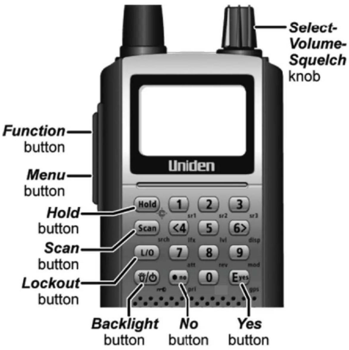
UBCD396XT
Operating the controls
Each button has at least two different actions which you control using the key combinations explained below.
- Tap : press the button and release it immediately
- Double tap : press the button twice, as quickly as possible (within 1 second)
- Press & hold : press the button and keep it pressed for at least 2 seconds before releasing it
- FUNCTION + tap : press and release FUNCTION, then tap the button
- FUNCTION + Double tap : press and release FUNCTION , then double tap the button
- FUNCTION + Press & hold : press and release FUNCTION, then press and hold the button
Using the FUNCTION button
When you tap FUNCTION, the scanner remembers the FUNCTION + key combination for the next 3 seconds; during this time, it displays an F icon at the top of the screen.
If you want the scanner to maintain the FUNCTION + key combination longer, press & hold FUNCTION. The scanner remembers the FUNCTION + key combination until the next time you tap FUNCTION; during this time, it displays Function Key Holding and flashes the F icon at the top of the screen.
Key functions in different operation modes
The keys have different functions in each operation mode:
- Scan and Search mode key functions
- Hold mode key functions
- Close Call mode key functions
• Priority Scan mode information
• GPS mode key functions - Tone Out mode key functions
• Band Scope mode key functions
• Available functions in Key Safe mode
Locking the Keypad
You can lock the keypad to prevent accidental interruptions of the scanner's current operation.
- To lock the keypad, press FUNCTION + tap BACKLIGHT. The scanner display shows Keypad Lock On and turns on the keypad lock icon in the upper left corner.
- All keys are disabled except for HOLD, BACKLIGHT, and SELECT-VOLUME-SQUELCH (Volume level only).
- To unlock the keypad, press FUNCTION + tap BACKLIGHT. The scanner display shows Keypad Lock Off and turns off the keypad lock icon.
7. Menu tree
Main menu
- Program System
- Program Location
- Srch/CloCall Opt
- Search for...
- Close Call
- Priority Scan
- Tone-Out for...
- Wired Clone
- Settings
Using the menu
• To open the menu, tap MENU.
- Turn the SELECT-VOLUME-SQUELCH knob to move the cursor and highlight menu items. The currently highlighted item appears in reversed-out text.
- To select the highlighted item or confirm an option setting, tap E-YES or press down on the SELECT-VOLUME-SQUELCH knob.
- To cancel an option setting, press NO.
• To go back one level in the menu, tap MENU.
- To exit the menu, press LOCKOUT. The scanner goes back to the operating mode it was in before you entered the menu.
UBCD396XT
8. Reading the display
The display icons vary depending on the status of the scanner and what you're doing at any given time. The diagram shows common icon locations, and table below lists the most common icons and their meanings:
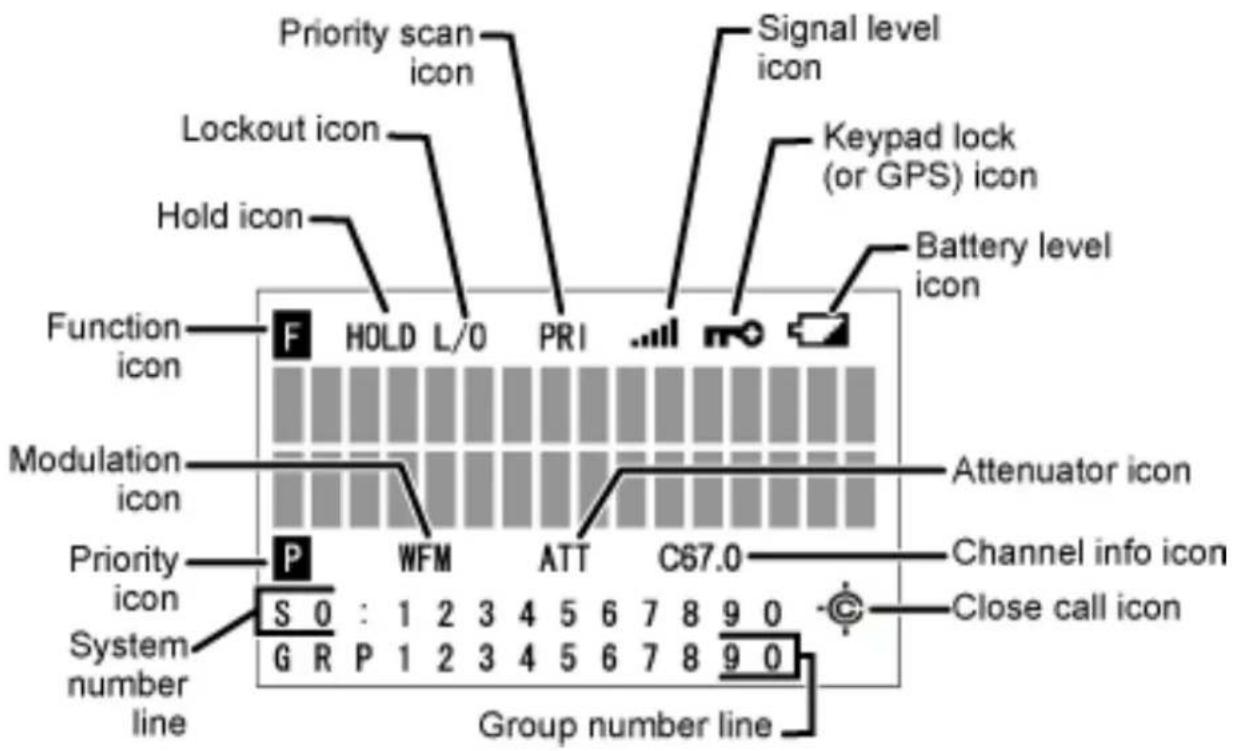
| Attenuator icon | Steady: The attenuator is turned on for the current channel. |
| Blinking: The attenuator is turned on globally (for all channels). | |
| Battery level icon(Handheld models only) | x.xx: The remaining battery voltage is displayed in place of the Xs. |
| Blinking icon: The battery is low. (If the AC adapter is connected while the icon is blinking, the battery is incorrectly installed, is the wrong type, or has gone bad.) | |
| Channel info icon | This icon has several available states:P25: The received signal is digitized voice (APCO P25)LNK: The current channel is configuredas a voice channel, but the scanner is receiving data on it.DAT: The current channel is configured as a control channel, and the scanner is receiving data on it.ENC: The received signal is encrypted P25 digitized voice, and the scanner has muted the audio.Cxx.x: The scanner has detected a CTCSS code; the received code is displayed in place of the Xs.DCSxxx: The scanner has detected a DCS code; the received code is displayed in place of the Xs.NAC: xxx: The scanner has detected a P25 network address code (NAC); the received code is displayed in place of the Xs. |
| Close call icon | Normal (open) icon:Steady: Close call priority mode is on.Blinking: Close Call Only mode is on, or the scanner has detected a close call signal. |
| Reversed (filled) icon:Steady: Close call DND mode is on.Blinking: Close call DND mode is on, and the scanner has detected a close call signal. | |
| Function icon | Steady: You tapped the FUNCTION key; the scanner will remember the FUNCTION + key combination for the next 3 seconds. |
| Blinking: You pressed & held the FUNCTION key: the scanner will remember the FUNCTION + key combination until you tap FUNCTION again. | |
| Group number line (GRP) | In Scan mode: The group Quick Key numbers (GQK) of any unlocked groups in the current system or site are displayed on this line. The GQK number of the group that is currently |
UBCD396XT
| being scanned blinks. | |
| In Hold mode: This line displays the GQK number of the current group only. | |
| In Custom Search mode: The numbers of any programmed search ranges are display on this line. The number of the custom range that is currently being searched blinks. | |
| Hold icon | The scanner is in Hold mode. |
| IFX icon | You switched to the intermediate frequency (IF exchange). |
| Keypad lock (or GPS) Icon | m0 : The keypad is locked. (Available only on handheld models.) |
| GPS: The scanner is receiving data from the GPS device. | |
| Lockout icon | The current channel is locked out. |
| Modulation icon | This icon displays the modulation type of the current channel: AM, FM, NFM, FMB, or WFM. |
| Priority icon | The current channel is set as a priority channel. |
| Priority scan icon (PRI) | Steady: Priority scan is turned on. |
| Blinking: Priority Plus scan is turned on. | |
| REP icon | The Repeater Find feature is turned on. |
| Signal level icon | This icon displays the strength of the current signal; the icon ranges from zero bars (no signal) to five bars (strong signal). |
| System number line (Sx:) | In Scan mode: The system/site Quick Key numbers (SQK) of any unlocked systems or sites are displayed on this line. The SQK number of the system or site that is currently being scanned blinks. For SQK numbers above 9, the tens digit replaces the X in the icon; the ones digits are shown on this line. |
| In Hold mode: This line displays the SQK number of the current system or site only. For SQK numbers above 9, the tens digit replaces the X in the icon; the ones digit is displayed on this line. | |
| In Service Search mode: The icon SCR replaces the System numbers if the broadcast screen feature is turned on. |
Special displays
In some operation modes, the display can be very different from the main display. These modes also have 2 or 3 different displays you can cycle through.
• Band Scope mode display
- Hold mode displays
- GPS mode display
9. Conventional Systems
Please note that these pages are meant as general instructions.
Since a conventional system is really a collection of frequencies, the first thing you need to know is the frequency for each channel you want to program.
Programming a Conventional System
To program a conventional system, you'll need to program the required elements in the following order:
Create a system
- Go to the Program System menu and choose New System.
- The scanner will prompt you for the System Type. Select Conventional.
- When the scanner prompts you confirm, tap YES.
- The scanner creates the system with a default name. Select Edit Name if you want to change it.
- If you need to change any of the system properties, you can do that now. Unless a property is Required, you can operate the system without changing the default settings.
System properties
All of these options can be found under your scanner's Program System menu. If necessary, the sub-menu and option name on each scanner are listed beside the property.
| Property | Option | name |
| Required | ||
| None | ||
| Recommended | ||
| Name Edit Name | ||
| Number tag Set Number Tag | ||
| Quick key Set Quick Key | ||
| Optional | ||
| Automatic Gain Control (AGC) | Set Audio AGC | |
| Delay time Set Delay Time | ||
| Hold time Set Hold Time | ||
UBCD396XT
| Lockout Set Lockout | |
| P25 wait time P25 Waiting Time | |
| Startup key Set Startup Key | |
| Available operations | |
| Copy a system Copy System | |
| Delete a system Delete System |
Create at least 1 channel group
Each conventional system can contain up to 20 channel groups, and all systems must contain at least 1 channel group.
-
On the Program System menu, select the system you just created.
-
Go to the Edit Group menu and select New Group.
-
If you need to change any of the channel group properties, you can do that now. Unless a property is Required, you can operate the system without changing the default settings.
Channel group properties
All of these options can be found by selecting the group name under your scanner's Edit Group menu. If necessary, the sub-menu and option name on each scanner are listed beside the property.
| Property | Option |
| Required | |
| None | |
| Recommended | |
| Name Edit Name | |
| Quick key Set Quick Key | |
| Optional | |
| Location information | Set Location Info |
| Lockout Set Lockout | |
| Available operations | |
| Delete a group Delete Group | |
name
Create at least 1 channel in each group
UBCD396XT
Each conventional system can contain up to 1000 channels in each group, and all groups must contain at least 1 channel.
- On the Edit Group menu, select the channel group you just created.
- Go to the Edit Channel menu and select New Channel.
- Input the frequency for this channel in MHz.
- If you need to change any of the channel properties, you can do that now. Unless a property is Required, you can operate the system without changing the default settings.
| Property | Option |
| Required | |
| Frequency Edit Frequency | |
| Recommended | |
| Analog/digital Set Audio Type | |
| • CTCSS/DCS | Set CTCSS/DCS (analog channels only) |
| • P25 Network Address (NAC) | P25 NAC Option (digital channels only) |
| Modulation Set Modulation | |
| Name Edit Name | |
| Number tag Set Number Tag | |
| Optional | |
| Alert Set Alert | |
| Attenuator Set Attenuator | |
| Lockout Set Lockout | |
| Priority Set Priority | |
| Volume Offset Volume Offset | |
| Available operations | |
| Copy a channel Copy Channel | |
| Delete a channel Delete Channel | |
name
UBCD396XT
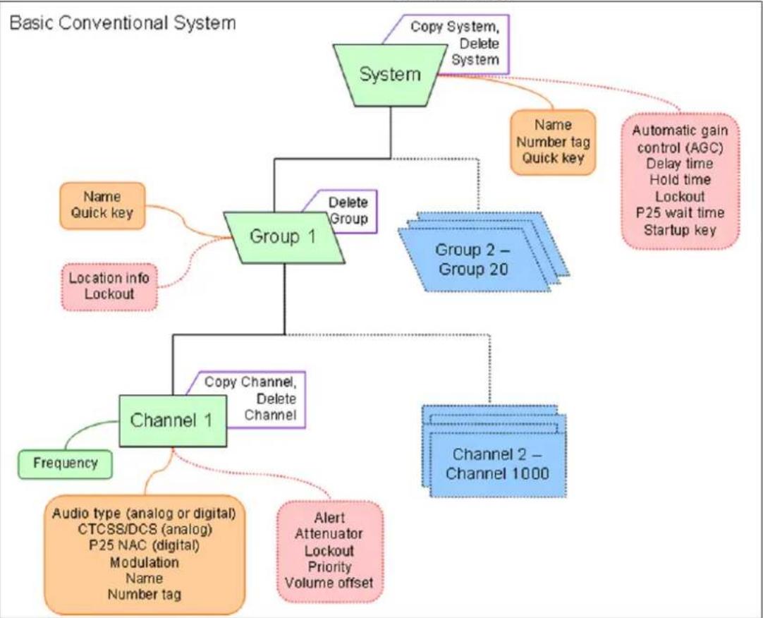
flowchart
graph TD
    A["Basic Conventional System"] --> B["System"]
    B --> C["Copy System, Delete System"]
    B --> D["Group 1"]
    D --> E["Delete Group"]
    D --> F["Channel 1"]
    F --> G["Frequency"]
    F --> H["Audio type (analog or digital) CTCSS/DCS (analog) P25 NAC (digital) Modulation Name Number tag"]
    F --> I["Alert Attenuator Lockout Priority Volume offset"]
    B --> J["Group 2 – Group 20"]
    J --> K["Name Number tag Quick key"]
    J --> L["Automatic gain control (AGC) Delay time Hold time Lockout P25 wait time Startup key"]
    J --> M["Channel 2 – Channel 1000"]
    C --> N["Name Quick key"]
    C --> O["Location info Lockout"]
System Layout Legend
Items
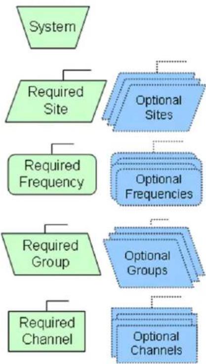
flowchart
graph TD
    A["System"] --> B["Required Site"]
    B --> C["Required Frequency"]
    C --> D["Required Group"]
    D --> E["Required Channel"]
    B --> F["Optional Sites"]
    C --> G["Optional Frequencies"]
    D --> H["Optional Groups"]
    E --> I["Optional Channels"]
Properties
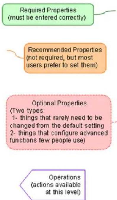
flowchart
graph TD
    A["Required Properties\n(must be entered correctly)"] --> B["Recommended Properties\n(not required, but most users prefer to set them)"]
    B --> C["Optional Properties\n(Two types:\n1- things that rarely need to be changed from the default setting\n2- things that configure advanced functions few people use)"]
    C --> D["Operations\n(actions available at this level)"]
| Frequency | Name (Alpha Tag) | Number Tag | CTCSS/DCS/NAC | Priority | Modulation | Alert |
| Channel information: | ||||||
| System Startup Key: | Location info: | |||||
| System Quick Key: | Group Name: | Group Quick Key: | ||||
| System Name: | System Number Tag: | |||||
Conventional System Worksheet
10. EDACS SCAT Systems
Please note that these pages are meant as general instructions. While most of the information here applies to all scanners, some options may not be available on certain scanner models. Model-specific options are indicated in the text.
Programming an EDACS SCAT System
To program an EDACS SCAT system, you'll need to program the required elements in following order:
Create a system
- Go to the Program System menu and choose New System.
- The scanner will prompt you for the System Type. Select EDCS.
- The scanner will prompt you for the sub-type. Select SCAT.
- When the scanner prompts you confirm, tap YES.
- The scanner creates the system with a default name. Select Edit Name if you want to change it.
- If you need to change any of the system properties, you can do that now. Unless a property is Required, you can operate the system without changing the default settings.
System properties
All of these options can be found under your scanner's Program System menu. If necessary, the sub-menu and option name on each scanner are listed beside the property.
| Property | Option |
| Required | |
| None | |
| Recommended | |
| Name Edit Name | |
| Number tag Set Number Tag | |
| Optional | |
| Automatic Gain Control (AGC) | Set Audio AGC |
| Delay time Set Delay Time | |
| Available operations | |
| Copy a system Copy | System |
| Delete a system Delete | System |
name
Create a site
Each EDACS SCAT system must contain exactly 1 site.
-
On the Program System menu, select the system you just created.
-
Go to the Edit Site menu.
-
If you need to change any of the site properties, you can do that now. Unless a property is Required, you can operate the system without changing the default settings.
Site properties
All of these options can be found under your scanner's Edit Site menu. If necessary, the sub-menu and option name on each scanner are listed beside the property.
| Property | Option |
| Required | |
| None | |
| Recommended | |
| Quick key Set Quick Key | |
| Optional | |
| Attenuator Set Attenuator | |
| Hold time Set Hold Time | |
| Location information Set Location Info | |
| Lockout Set Lockout | |
| Modulation Set Modulation | |
| Startup key Set Startup Key | |
| Available operations | |
| None | |
name
Create at least 1 frequency
Each EDACS SCAT system must contain at least 1 frequency in its site.
- Open the Edit Site menu.
- Go to the Set Frequencies sub-menu and select New Frequency.
- Enter at least 1 frequency for this site.
UBCD396XT
- If you need to change any of the frequency properties, you can do that now. Unless a property is Required, you can operate the system without changing the default settings.
Frequency properties
All of these options can be found by selecting the frequency under the Set Frequencies sub-menu. If necessary, the sub-menu and option name on each scanner are listed beside the property.
| Property | Option |
| Required | |
| None | |
| Recommended | |
| Number tag Set Number Tag | |
| Optional | |
| Volume Offset Volume Offset | |
| Lockout Set Lockout | |
| Available operations | |
| Delete a frequency Delete Frequency | |
name
EDACS SCAT System
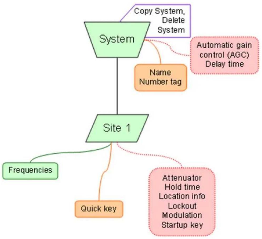
flowchart
graph TD
    A["System"] --> B["Site 1"]
    B --> C["Frequencies"]
    B --> D["Quick key"]
    A --> E["Copy System, Delete System"]
    E --> F["Name Number tag"]
    F --> G["Automatic gain control (AGC) Delay time"]
    B --> H["Attenuator Hold time Location info Lockout Modulation Startup key"]
11. EDACS Trunked Systems
Please note that these pages are meant as general instructions.
This section deals with EDACS Wide or standard systems. This includes EDACS systems that use ESK.
No special setting is needed to enable ESK tracking on an EDACS system. Note that the scanner cannot decode EDACS ProVoice.
Programming an EDACS System
To program an EDACS system, you'll need to program the required elements in following order:
Create a system
- Go to the Program System menu and choose New System.
- The scanner will prompt you for the System Type. Select EDCS.
- The scanner will prompt you for the sub-type. Select Wide/Narrow.
- When the scanner prompts you confirm, tap YES.
- The scanner creates the system with a default name. Select Edit Name if you want to change it.
- If you need to change any of the system properties, you can do that now. Unless a property is Required, you can operate the system without changing the default settings.
System properties
All of these options can be found under your scanner's Program System menu. If necessary, the submenu and option name on each scanner are listed beside the property.
| Property | Option |
| Required | |
| None | |
| Recommended | |
| Name Edit Name | |
| Number tag Set Number Tag | |
| Optional | |
name
UBCD396XT
| Automatic Gain Control(AGC) | Set Audio AGC |
| Delay time Set Delay Time | |
| Emergency alert Emergency Alert | |
| ID format Set ID Format (AFS) or (DEC) | |
| ID scan/search ID Scan/Search | |
| Priority ID scan Priority ID Scan | |
| Available operations | |
| Copy a system Copy System | |
| Delete a system Delete System | |
| Review locked-out IDs Rvw ID:Srch L/O | |
| Clear all locked-out IDs Clr All L/O IDs | |
Create at least 1 site
Each EDACS system can contain up to 256 sites, and all systems must contain at least 1 site.
-
On the Program System menu, select the system you just created.
-
Go to the Edit Site menu and select New Site.
-
If you need to change any of the site properties, you can do that now. Unless a property is Required, you can operate the system without changing the default settings.
Site properties
All of these options can be found under your scanner's Edit Site menu. If necessary, the sub-menu and option name on each scanner are listed beside the property.
| Property | Option |
| Required | |
| Site type Set Site | Type |
| Recommended | |
| Name Edit Name | |
| Quick key Set Quick Key | |
| Optional | |
name
UBCD396XT
| Attenuator Set Attenuator | |
| Hold time Set Hold Time | |
| Location information Set Location Info | |
| Lockout Set Lockout | |
| Modulation Set Modulation | |
| Startup key Set Startup Key | |
| Available operations | |
| Delete a site Delete Site |
Create at least 1 frequency in each site
Each trunked system can contain up to 30 frequencies in each site, and all sites must contain at least 1 frequency.
- On the Edit Site menu, select the site you just created.
- Go to the Set Frequencies sub-menu and select New Frequency.
- Enter at least 1 frequency for this site.
- When you enter a new frequency, the scanner will prompt you for the logical channel number or LCN for that frequency. Enter a number from 1 through 30.
- If you need to change any of the frequency properties, you can do that now. Unless a property is Required, you can operate the system without changing the default settings.
Frequency properties
All of these options can be found by selecting the frequency under the Set Frequencies sub-menu. If necessary, the sub-menu and option name on each scanner are listed beside the property.
| Property | Option |
| Required | |
| Logical channel number Input LCN | |
| Recommended | |
| None | |
| Optional | |
| Lockout Set Lockout | |
| Available operations | |
| Delete a frequency | Delete Frequency |
name
Programming a system for Scanning
Once you create the system and at least 1 site, you can Search the system with no problems. However, if you want to Scan the system, you'll need to program the required elements in following order:
Create at least 1 channel group
Each EDACS system can contain up to 20 channel groups, and any system you want to scan must contain at least 1 channel group.
- On the Program System menu, select the system you just created.
- Go to the Edit Group menu and select New Group.
- If you need to change any of the channel group properties, you can do that now. Unless a property is Required, you can operate the system without changing the default settings.
Channel group properties
All of these options can be found by selecting the group name under your scanner's Edit Group menu. If necessary, the sub-menu and option name on each scanner are listed beside the property.
| Property | Option |
| Required | |
| None | |
| Recommended | |
| Name Edit Name | |
| Quick key Set Quick Key | |
| Optional | |
| Location information Set Location Info | |
| Lockout Set Lockout | |
| Available operations | |
| Delete a group Delete Group | |
name
Create at least 1 channel in each group
Each trunked system can contain up to 500 channels.
UBCD396XT
-
On the Edit Group menu, select the channel group you just created.
-
Go to the Edit Channel menu and select New Channel.
-
Input the Talk Group ID (TGID) for this channel.
-
If you need to change any of the channel properties, you can do that now. Unless a property is Required, you can operate the system without changing the default settings.
Channel properties
All of these options can be found by selecting the channel name your scanner's Edit Channel menu. If necessary, the sub-menu and option name on each scanner are listed beside the property.
| Property | Option |
| Required | |
| TGID Edit TGID | |
| Recommended | |
| Name Edit Name | |
| Number tag Set Number Tag | |
| Optional | |
| Alert Set Alert | |
| Lockout Set Lockout | |
| Priority Set Priority | |
| Volume Offset Volume Offset | |
| Available operations | |
| Copy a channel Copy Channel | |
| Delete a channel Delete Channel | |
name
UBCD396XT
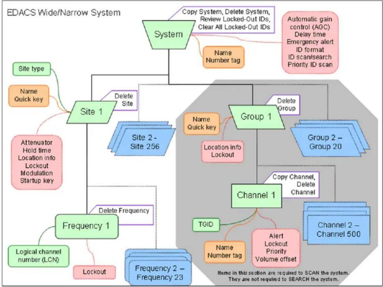
flowchart
graph TD
    A["EDACS Wide/Narrow System"] --> B["System"]
    B --> C["Site 1"]
    B --> D["Group 1"]
    B --> E["Channel 1"]
    C --> F["Site type"]
    C --> G["Name Quick key"]
    C --> H["Attenuator Hold time Location info Lockout Modulation Startup key"]
    C --> I["Frequency 1"]
    C --> J["Logical channel number (LCN)"]
    C --> K["Lockout"]
    D --> L["Delete Site"]
    D --> M["Delete Group"]
    D --> N["Location Info Lockout"]
    D --> O["Copy Channel, Delete Channel"]
    D --> P["TGID"]
    D --> Q["Alert Lockout Priority Volume offset"]
    D --> R["Channel 2 – Channel 500"]
    D --> S["Automatic gain control (AGC) Delay time Emergency alert ID format ID scan/search Priority ID scan"]
    D --> T["Copy System, Delete System, Review Locked-Out IDs, Clear All Locked-Out IDs"]
    D --> U["Name Number tag"]
    D --> V["Delete Frequency"]
    D --> W["Frequency 2 – Frequency 23"]
| Talk Group ID (T6ID) | Name (Alpha Tag) | Number Tag | Priority | Alert |
EDACS/LTR System Worksheet A
| System Name: | System Number Tag: | ||||||
| Site Name: | Site Type: | Site Quick Key: | |||||
| Site Number Tag: | Location Info: | Site Startup Key: | |||||
| Channel Information: | |||||||
| Frequency | Name (Alpha Tag) | Number Tag | Priority | Modulation | Alert | ||
EDACS/LTR System Worksheet B
12. LTR Trunked Systems
Please note that these pages are meant as general instructions.
Programming an LTR System
To program an LTR system, you'll need to program the required elements in following order:
Create a system
- Go to the Program System menu and choose New System.
- The scanner will prompt you for the System Type. Select LT.
- When the scanner prompts you confirm, tap YES.
- The scanner creates the system with a default name. Select Edit Name if you want to change it.
- If you need to change any of the system properties, you can do that now. Unless a property is Required, you can operate the system without changing the default settings.
System properties
All of these options can be found under your scanner's Program System menu. If necessary, the submenu and option name on each scanner are listed beside the property.
| Property | Option |
| Required | |
| None | |
| Recommended | |
| Name Edit Name | |
| Number tag Set Number Tag | |
| Optional | |
| Automatic Gain Control (AGC) | Set Audio AGC |
| Delay time Set Delay Time | |
| ID scan/search ID Scan/Search | |
| Priority ID scan Priority ID Scan | |
name
UBCD396XT
| Available operations | |
| Copy a system Copy System | |
| Delete a system Delete System | |
| Review locked-out IDs Rvw ID:Srch L/O | |
| Clear all locked-out IDs Clr All L/O IDs |
Create at least 1 site
Each LTR system can contain up to 256 sites, and all systems must contain at least 1 site.
- On the Program System menu, select the system you just created.
- Go to the Edit Site menu and select New Site .
- If you need to change any of the site properties, you can do that now. Unless a property is Required, you can operate the system without changing the default settings.
Site properties
All of these options can be found under your scanner's Edit Site menu. If necessary, the sub-menu and option name on each scanner are listed beside the property.
| Property | Option |
| Required | |
| None | |
| Recommended | |
| Name Edit Name | |
| Quick key Set Quick Key | |
| Optional | |
| Attenuator Set Attenuator | |
| Hold time Set Hold Time | |
| Location information Set Location Info | |
| Lockout Set Lockout | |
| Modulation Set Modulation | |
| Startup key Set Startup Key | |
| Available operations | |
| Delete a site Delete Site | |
name
Create at least 1 frequency in each site
Each LTR system can contain up to 20 frequencies in each site, and all sites must contain at least 1 frequency.
- On the Edit Site menu, select the site you just created.
- Go to the Set Frequencies sub-menu and select New Frequency.
- Enter at least 1 frequency for this site.
- When you enter a new frequency, the scanner will prompt you for the logical channel number or LCN for that frequency. Enter a number from 1 through 20.
- If you need to change any of the frequency properties, you can do that now. Unless a property is Required, you can operate the system without changing the default settings.
Frequency properties
All of these options can be found by selecting the frequency under the Set Frequencies sub-menu. If necessary, the sub-menu and option name on each scanner are listed beside the property.
| Property | Option |
| Required | |
| Logical channel number Input LCN | |
| Recommended | |
| None | |
| Optional | |
| Lockout Set Lockout | |
| Available operations | |
| Delete a frequency Delete Frequency | |
name
Programming a system for Scanning
Once you create the system and at least 1 site, you can Search the system with no problems. However, if you want to Scan the system, you'll need to program the required elements in following order.
Create a channel group
Each LTR system can contain up to 20 channel groups.
- On the Program System menu, select the system you just created.
- Go to the Edit Group menu and select New Group.
- If you need to change any of the channel group properties, you can do that now. Unless a property is Required, you can operate the system without changing the default settings.
Channel group properties
All of these options can be found by selecting the group name under your scanner's Edit Group menu. If necessary, the sub-menu and option name on each scanner are listed beside the property.
| Property | Option |
| Required | |
| None | |
| Recommended | |
| Name Edit Name | |
| Quick key Set Quick Key | |
| Optional | |
| Location information Set Location Info | |
| Lockout Set Lockout | |
| Available operations | |
| Delete a group Delete Group | |
name
Create a channel in each group
Each trunked system can contain up to 500 channels.
- On the Edit Group menu, select the channel group you just created.
- Go to the Edit Channel menu and select New Channel.
- Input the Talk Group ID (TGID) for this channel.
UBCD396XT
- If you need to change any of the channel properties, you can do that now. Unless a property is Required, you can operate the system without changing the default settings.
Channel properties
All of these options can be found by selecting the channel name your scanner's Edit Channel menu. If necessary, the sub-menu and option name on each scanner are listed beside the property.
| Property | Option | name |
| Required | ||
| TGID Edit TGID | ||
| Recommended | ||
| Name Edit Name | ||
| Number tag Set Number Tag | ||
| Optional | ||
| Alert Set Alert | ||
| Lockout Set Lockout | ||
| Priority Set Priority | ||
| Volume Offset Volume Offset | ||
| Available operations | ||
| Copy a channel Copy Channel | ||
| Delete a channel Delete Channel | ||
UBCD396XT
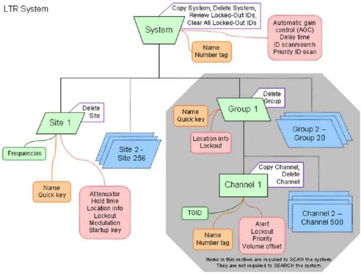
flowchart
graph TD
    A["LTR System"] --> B["System"]
    B --> C["Copy System, Delete System, Review Locked-Out IDs, Clear All Locked-Out IDs"]
    B --> D["Automatic gain control (AGC) Delay time ID scan/search Priority ID scan"]
    B --> E["Name Number tag"]
    B --> F["Site 1"]
    F --> G["Delete Site"]
    F --> H["Site 2 - Site 256"]
    H --> I["Frequencies"]
    H --> J["Name Quick key"]
    H --> K["Attenuator Hold time Location info Lockout Modulation Startup key"]
    B --> L["Group 1"]
    L --> M["Delete Group"]
    L --> N["Group 2 - Group 20"]
    L --> O["Channel 1"]
    O --> P["Copy Channel, Delete Channel"]
    O --> Q["Channel 2 - Channel 500"]
    O --> R["TQID"]
    R --> S["Alert Lockout Priority Volume offset"]
    R --> T["Name Number tag"]
    R --> U["Location info Lockout"]
13. Motorola Trunked Systems
Please note that these pages are meant as general instructions.
A Motorola system can be an 800 MHz, 400 MHz (UHF), or 100-200 MHz (VHF) system.
Programming a Motorola System
To program a Motorola system, you'll need to program the required elements in following order:
Create a system
- Go to the Program System menu and choose New System.
- The scanner will prompt you for the System Type. Select MOT.
- When the scanner prompts you confirm, tap YES.
- The scanner creates the system with a default name. Select Edit Name if you want to change it.
- If you need to change any of the system properties, you can do that now. Unless a property is Required, you can operate the system without changing the default settings.
System properties
All of these options can be found under your scanner's Program System menu. If necessary, the submenu and option name on each scanner are listed beside the property.
| Property | Option |
| Required | |
| Fleet map | Edit Fleet Map (Required for Motorola Type I or Type I/II Hybrid systems only) |
| Recommended | |
| Name | Edit Name |
| Number tag | Set Number Tag |
| Optional | |
| Automatic Gain Control (AGC) | Set Audio AGC |
name
UBCD396XT
| Delay time | Set Delay Time |
| Emergency alert | Emergency Alert |
| ID format | Set ID Format (DEC/HEX) |
| ID scan/search | ID Scan/Search |
| Priority ID scan | Priority ID Scan |
| Status bit | Set Status Bit |
| End Code | Set End Code |
| Available operations | |
| Copy a system | Copy System |
| Delete a system | Delete System |
| Review locked-out IDs | Rvw ID:Srch L/O |
| Clear all locked-out IDs | Clr All L/O IDs |
Create at least 1 site
Each Motorola system can contain up to 256 sites, and all systems must contain at least 1 site.
- On the Program System menu, select the system you just created.
- Go to the Edit Site menu and select New Site.
- If you need to change any of the site properties, you can do that now. Unless a property is Required, you can operate the system without changing the default settings.
Site properties
All of these options can be found under your scanner's Edit Site menu. If necessary, the sub-menu and option name on each scanner are listed beside the property.
| Property | Option |
| Required | |
| Band plan | Edit Band Plan |
| Recommended | |
| Name | Edit Name |
| Quick key | Set Quick Key |
| Optional | |
| Attenuator | Set Attenuator |
name
UBCD396XT
| Hold time | Set Hold Time |
| Location information | Set LocationInfo |
| Lockout | Set Lockout |
| Modulation | Set Modulation |
| P25 wait time | P25 Waiting Time |
| Startup key | Set Startup Key |
| Available operations | |
| Delete a site | Delete Site |
Create at least 1 frequency in each site
Each site must contain at least 1 frequency.
- On the Edit Site menu, select the site you just created.
- Go to the Set Frequencies sub-menu and select New Frequency.
- Enter at least 1 frequency for this site.
- If you need to change any of the frequency properties, you can do that now. Unless a property is Required, you can operate the system without changing the default settings.
Frequency properties
All of these options can be found by selecting the frequency under the Set Frequencies sub-menu. If necessary, the sub-menu and option name on each scanner are listed beside the property.
| Property | Option |
| Required | |
| None | |
| Recommended | |
| None | |
| Optional | |
| Lockout Set Lockout | |
| Available operations | |
| Delete a frequency Delete Frequency | |
name
Programming a system for Scanning
UBCD396XT
Once you create the system and at least 1 site, you can scan the system in ID Search mode. In this mode, the scanner stops on all system traffic for talk groups you have not locked out. If you want to use ID Scan mode, you'll need to program channels into the system. In ID Scan, the scanner only stops on talk groups you have programmed into a channel.
Create a channel group
Each Motorola system can contain up to 20 channel groups.
-
On the Program System menu, select the system you just created.
-
Go to the Edit Group menu and select New Group.
-
If you need to change any of the channel group properties, you can do that now. Unless a property is Required, you can operate the system without changing the default settings.
Channel group properties
(All of these options can be found by selecting the group name under the Edit Group menu. If necessary, the sub-menu and the exact option name are listed beside each property.)
| Required | None |
| Recommended | Name (Edit Name) |
| Quick key (Set Quick Key) | |
| Optional | Location information (Set LocationInfo) |
| Lockout (Set Lockout) | |
| Available operations | Delete Group |
Create a channel
Each trunked system can contain up to 500 channels.
-
On the Edit Group menu, select the channel group you just created.
-
Go to the Edit Channel menu and select New Channel.
-
Input the Talk Group ID (TGID) for this channel.
-
If you need to change any of the channel properties, you can do that now. Unless a property is Required, you can operate the system without changing the default settings.
Channel properties
(All of these options can be found by selecting the channel name under the Edit Channel menu. If necessary, the sub-menu and the exact option name are listed beside each property.)
| Required | TGID (Edit TGID) |
| Recommended | Audio type (Analog or digital) (Set Audio Type) |
| Name (Edit Name) | |
| Number tag (Set Number Tag) | |
| Optional | Alert (Set Alert) |
| Lockout (Set Lockout) | |
| Priority (Set Priority) | |
| Volume Offset | |
| Available operations | Copy Channel |
| Delete Channel |
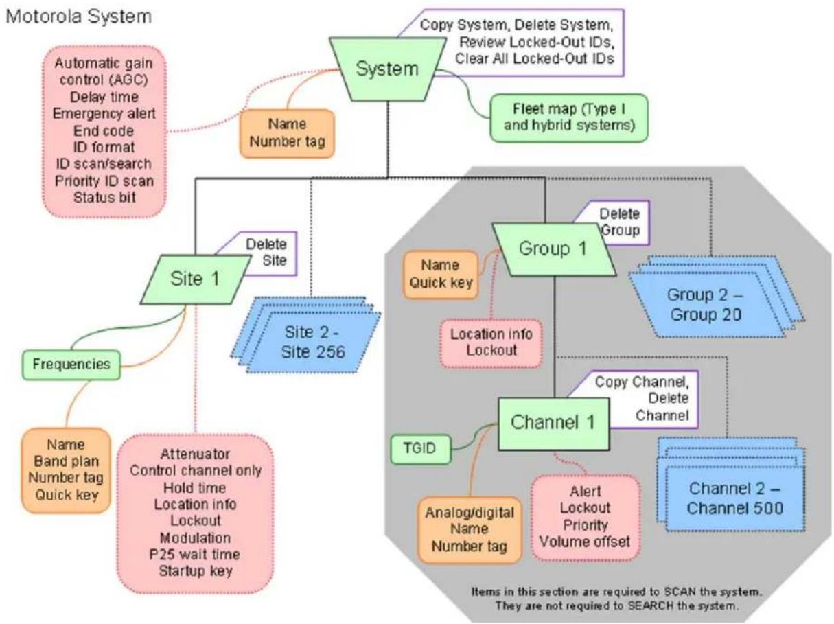
flowchart
graph TD
    A["Motorola System"] --> B["System"]
    B --> C["Name Number tag"]
    B --> D["Fleet map (Type I and hybrid systems)"]
    B --> E["Copy System, Delete System, Review Locked-Out IDs, Clear All Locked-Out IDs"]
    B --> F["Site 1"]
    F --> G["Delete Site"]
    F --> H["Site 2 - Site 256"]
    F --> I["Frequencies"]
    I --> J["Name Band plan Number tag Quick key"]
    F --> K["Attenuator Control channel only Hold time Location info Lockout Modulation P25 wait time Startup key"]
    B --> L["Group 1"]
    L --> M["Delete Group"]
    L --> N["Location info Lockout"]
    L --> O["Channel 1"]
    O --> P["Copy Channel, Delete Channel"]
    O --> Q["TGID"]
    Q --> R["Analog/digital Name Number tag"]
    O --> S["Alert Lockout Priority Volume offset"]
    O --> T["Channel 2 - Channel 500"]
    style A fill:#d4edda,stroke:#333
    style B fill:#e6f7ff,stroke:#333
    style C fill:#e6f7ff,stroke:#333
    style D fill:#e6f7ff,stroke:#333
    style E fill:#e6f7ff,stroke:#333
    style F fill:#e6f7ff,stroke:#333
    style G fill:#e6f7ff,stroke:#333
    style H fill:#e6f7ff,stroke:#333
    style I fill:#e6f7ff,stroke:#333
    style J fill:#e6f7ff,stroke:#333
    style K fill:#e6f7ff,stroke:#333
    style L fill:#e6f7ff,stroke:#333
    style M fill:#e6f7ff,stroke:#333
    style N fill:#e6f7ff,stroke:#333
    style O fill:#e6f7ff,stroke:#333
    style P fill:#e6f7ff,stroke:#333
    style Q fill:#e6f7ff,stroke:#333
    style R fill:#e6f7ff,stroke:#333
    style S fill:#e6f7ff,stroke:#333
    style T fill:#e6f7ff,stroke:#333
| System Name: System Number Tag: | ||||
| (available types: Type I, Type II: 800 MHz/Standard, 800 MHz/SPinter, UHF, VHF) | ||||
| Channel information: | ||||
| T6ID | Number Tag | Name (Alpha Tag) | Priority Alert | |
Motorola System Worksheet A (scan)
| System Type: | Site Name: | Location Info: | ||||||
| (available types: Type I, Type II: 800 MHz/Standard, 800 MHz/Splinter, UHF, VHF) | Location Info: | |||||||
| Frequency: | Name (Alpha Tag) | Number Tag | Band Plan Information: | |||||
| Band Plan Information: | ||||||||
| Frequency: | Name (Alpha Tag) | Number Tag | Band Plan Information: | |||||
| Frequency: | Name (Alpha Tag) | Number Tag | Band Plan Information: | |||||
| Frequency: | Name (Alpha Tag) | Number Tag | Band Plan Information: | |||||
| Frequency: | Name (Alpha Tag) | Number Tag | Band Plan Information: | |||||
| Frequency: | Name (Alpha Tag) | Number Tag | Band Plan Information: | |||||
| Band Plan Information: | ||||||||
| Frequency: | Name (Alpha Tag) | Number Tag | Band Plan Information: | |||||
| Frequency: | Name (Alpha Tag) | Number Tag | Band Plan Information: | |||||
| Frequency: | Name (Alpha Tag) | Number Tag | Band Plan Information: | |||||
Motorola System Worksheet B (search)
UBCD396XT
| Fleet Map #: | |
| Block Information: | |
| Block | Size Code |
| Block 0 | |
| Block 1 | |
| Block 2 | |
| Block 3 | |
| Block 4 | |
| Block 5 | |
| Block 6 | |
| Block 7 | |
| Fleet Map #: | |
| Block Information: | |
| Block | Size Code |
| Block 0 | |
| Block 1 | |
| Block 2 | |
| Block 3 | |
| Block 4 | |
| Block 5 | |
| Block 6 | |
| Block 7 | |
| Fleet Map #: | |
| Block Information: | |
| Block | Size Code |
| Block 0 | |
| Block 1 | |
| Block 2 | |
| Block 3 | |
| Block 4 | |
| Block 5 | |
| Block 6 | |
| Block 7 | |
| Fleet Map #: | |
| Block Information: | |
| Block | Size Code |
| Block 0 | |
| Block 1 | |
| Block 2 | |
| Block 3 | |
| Block 4 | |
| Block 5 | |
| Block 6 | |
| Block 7 | |
| Fleet Map #: | |
| Block Information: | |
| Block | Size Code |
| Block 0 | |
| Block 1 | |
| Block 2 | |
| Block 3 | |
| Block 4 | |
| Block 5 | |
| Block 6 | |
| Block 7 | |
| Fleet Map #: | |
| Block Information: | |
| Block | Size Code |
| Block 0 | |
| Block 1 | |
| Block 2 | |
| Block 3 | |
| Block 4 | |
| Block 5 | |
| Block 6 | |
| Block 7 | |
| Fleet Map #: | |
| Block Information: | |
| Block | Size Code |
| Block 0 | |
| Block 1 | |
| Block 2 | |
| Block 3 | |
| Block 4 | |
| Block 5 | |
| Block 6 | |
| Block 7 | |
| Fleet Map #: | |
| Block Information: | |
| Block | Size Code |
| Block 0 | |
| Block 1 | |
| Block 2 | |
| Block 3 | |
| Block 4 | |
| Block 5 | |
| Block 6 | |
| Block 7 | |
Motorola System Worksheet B (Fleet Maps)
14. Motorola fleet maps
Preset Fleet Maps
The scanner contains 16 pre-programmed fleet maps you can select. The table below gives the size code for each block of the preset fleet maps:
| Block number | 0 | 1 | 2 | 3 | 4 | 5 | 6 | |
| Preset 1 1 | 1 11 11 | 11 | 11 | 11 | 11 | 11 | ||
| Preset 2 4 | 4 4 4 | 4 4 4 | 4 | |||||
| Preset 3 4 | 4 4 4 | 4 4 12 | ||||||
| Preset 4 | 12 | 4 | 4 | 4 | 4 | 4 | 4 | |
| Preset 5 | 4 | 4 | 12 | 4 | 4 | 4 | 4 | |
| Preset 6 3 | 10 4 4 | 12 | 12 | |||||
| Preset 7 | 10 | 10 | 11 | 4 | 4 | 4 | 4 | 4 |
| Preset 8 1 | 1 2 2 | 3 3 4 | 4 | |||||
| Preset 9 4 | 4 0 0 | 0 0 0 | 0 | |||||
| Preset 10 0 | 0 0 0 | 0 | 0 4 4 | |||||
| Preset 11 4 | 0 | 0 0 0 | 0 0 0 | |||||
| Preset 12 0 | 0 | 0 0 0 | 0 0 4 | |||||
| Preset 13 | 3 | 3 | 11 | 4 | 4 | 0 | 0 | |
| Preset 14 | 4 | 3 | 10 | 4 | 4 | 4 | 12 | |
| Preset 15 4 | 4 | 4 11 | 11 0 12 | |||||
| Preset 16 | 3 | 10 | 10 | 11 | 0 | 0 | 12 | |
Custom Fleet Maps
To program a custom fleet map, select Custom under the Edit Fleet Map option. Then, select the appropriate size code for each block. Remember, not all size codes are available for all blocks:
| Block | Valid Size Codes |
| Block0 | 0 - 14 |
| Block | 0 - 13 (14 not valid) |
UBCD396XT
| 1 | |
| Block 2 | 0 - 13 (14 not valid) |
| Block 3 | 0 - 13 (14 not valid) |
| Block 4 | 0 - 13 (14 not valid) |
| Block 5 | 0 - 12 (13, 14 not valid) |
| Block 6 | 0 - 12 (13, 14 not valid) |
| Block 7 | 0 - 11 (12, 13, 14 not valid) |
How Fleet Maps Work
Blocks
Talk Group IDs can range from 0 to 65,535. To make it easier to handle this many IDs, the system divides the TGID range into 8 equal blocks :
| Block | Starting ID | Ending ID |
| Block 0 | 0 | 8191 |
| Block 1 | 8192 | 16383 |
| Block 2 | 16384 | 24575 |
| Block 3 | 24576 | 32767 |
| Block 4 | 32768 | 40959 |
| Block 5 | 40960 | 49151 |
| Block 6 | 49152 | 57343 |
| Block 7 | 57344 | 65535 |
Each block is assigned a size code based on the way the control channel sends the TGID data. Note that codes 12, 13, and 14 take up more than one block:
| Size Code | Fleet / SubFleet? / ID | Number of Blocks Needed |
| 0 (as Type II ID) 1 | ||
| 1 128 | /4/16 1 | |
| 2 16/ | 8/64 1 | |
| 3 8/8 | /128 1 | |
| 4 1/1 | 6/512 1 | |
| 5 64/ | 4/32 1 | |
| 6 32/ | 8/32 1 | |
| 7 32/ | 4/64 1 | |
| 8 16/ | 4/128 1 | |
| 9 8/4 | /256 1 | |
| 10 4/8 | /256 1 | |
| 11 2/ | 16/256 1 | |
| 12 1/ | 16/1024 | 2 |
| 13 1/ | 16/2048 | 4 |
| 14 1/ | 16/4096 | 8 |
15. Standard P25 Trunked Systems
This section deals with standard Project 25 or P25 systems.
Programming a P25 System
To program a P25 system, you'll need to program the required elements in following order:
Create a system
- Go to the Program System menu and choose New System.
- The scanner will prompt you for the System Type. Select P25.
- The scanner will prompt you for the sub-type. Select Standard trunk.
- When the scanner prompts you confirm, tap YES.
- The scanner creates the system with a default name. Select Edit Name if you want to change it.
- If you need to change any of the system properties, you can do that now. Unless a property is Required, you can operate the system without changing the default settings.
System properties
All of these options can be found under your scanner's Program System menu. If necessary, the submenu and option name on each scanner are listed beside the property.
| Property | Option | name |
| Required | ||
| None | ||
| Recommended | ||
| Name Edit Name | ||
| Number tag Set Number Tag | ||
| Optional | ||
| Automatic Gain Control (AGC) | Set Audio AGC | |
| Delay time Set Delay Time | ||
| ID format Set ID Format (DEC/HEX) | ||
| ID scan/search ID Scan/Search | ||
| Priority ID scan Priority ID Scan | ||
| Available operations | ||
| Copy a system Copy System | ||
UBCD396XT
Delete a system Delete System
Review locked-out IDs Rvw ID:Srch L/O
Clear all locked-out IDs Clr All L/O IDs
Create at least 1 site
All systems must contain at least 1 site.
- On the Program System menu, select the system you just created.
- Go to the Edit Site menu and select New Site.
- If you need to change any of the site properties, you can do that now. Unless a property is Required, you can operate the system without changing the default settings.
Site properties
All of these options can be found under your scanner's Edit Site menu. If necessary, the sub-menu and option name on each scanner are listed beside the property.
Property
Option
name
Required
None
Recommended
Band plan Edit Band Plan
Name Edit Name
Quick key Set Quick Key
Optional
Attenuator Set Attenuator
Hold time Set Hold Time
Location information Set LocationInfo
Lockout Set Lockout
Startup key Set Startup Key
Available operations
Delete a site Delete Site
Create at least 1 frequency in each site
All sites must contain at least 1 frequency.
- On the Edit Site menu, select the site you just created.
UBCD396XT
-
Go to the Set Frequencies sub-menu and select New Frequency.
-
Enter at least 1 frequency for this site.
-
If you need to change any of the frequency properties, you can do that now. Unless a property is Required, you can operate the system without changing the default settings.
Frequency properties
All of these options can be found by selecting the frequency under the Set Frequencies sub-menu. If necessary, the sub-menu and option name on each scanner are listed beside the property.
| Property | Option |
| Required | |
| None | |
| Recommended | |
| None | |
| Optional | |
| Lockout Set Lockout | |
| Available operations | |
| Delete a frequency Delete Frequency | |
Name
Programming a system for Scanning
Once you create the system and at least 1 site, you can Search the system with no problems. However, if you want to Scan the system, you'll need to program the required elements in following order.
Create a channel group
Each P25 system can contain up to 20 channel groups.
-
On the Program System menu, select the system you just created.
-
Go to the Edit Group menu and select New Group.
-
If you need to change any of the channel group properties, you can do that now. Unless a property is Required, you can operate the system without changing the default settings.
Channel group properties
All of these options can be found by selecting the group name under your scanner's Edit Group menu. If necessary, the sub-menu and option name on each scanner are listed beside the property.
| Property | Option |
| Required | |
| None | |
| Recommended | |
| Name Edit Name | |
| Quick key Set Quick Key | |
| Optional | |
| Location information Set LocationInfo | |
| Lockout Set Lockout | |
| Available operations | |
| Delete a group Delete Group | |
name
Create a channel in a group
Each trunked system can contain up to 500 channels.
- On the Edit Group menu, select the channel group you just created.
- Go to the Edit Channel menu and select New Channel.
- Input the Talk Group ID (TGID) for this channel.
- If you need to change any of the channel properties, you can do that now. Unless a property is Required, you can operate the system without changing the default settings.
Channel properties
All of these options can be found by selecting the channel name your scanner's Edit Channel menu. If necessary, the sub-menu and option name on each scanner are listed beside the property.
| Property | Option |
| Required | |
| TGID Edit TGID | |
name
UBCD396XT
| Recommended | |
| Name Edit Name | |
| Number tag Set Number Tag | |
| Optional | |
| Alert Set Alert | |
| Priority Set Priority | |
| Volume Offset Volume Offset | |
| Lockout Set Lockout | |
| Available operations | |
| Copy a channel Copy Channel | |
| Delete a channel Delete Channel | |
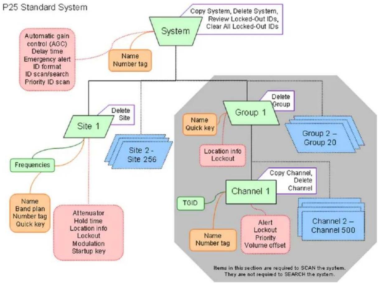
flowchart
graph TD
    A["System"] --> B["Automatic gain control (AGC) Delay time Emergency alert ID format ID scan/search Priority ID scan"]
    A --> C["Copy System, Delete System, Review Locked-Out IDs, Clear All Locked-Out IDs"]
    A --> D["Name Number tag"]
    A --> E["Delete Site"]
    A --> F["Site 1"]
    A --> G["Site 2 - Site 256"]
    A --> H["Frequencies"]
    H --> I["Name Band plan Number tag Quick key"]
    A --> J["Attenuator Hold time Location info Lockout Modulation Startup key"]
    A --> K["Delete Group"]
    K --> L["Group 1"]
    L --> M["Delete Group"]
    L --> N["Location info Lockout"]
    L --> O["Channel 1"]
    O --> P["Copy Channel, Delete Channel"]
    O --> Q["Alert Lockout Priority Volume offset"]
    O --> R["Channel 2 - Channel 500"]
    O --> S["TGID"]
    S --> T["Name Number tag"]
    L --> U["Group 2 - Group 20"]
UBCD396XT
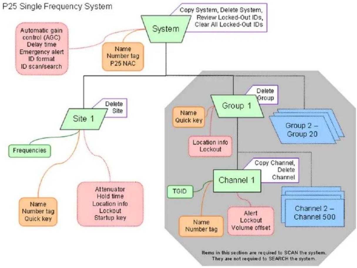
flowchart
graph TD
    A["System"] --> B["Automatic gain control (AGC) Delay time Emergency alert ID format ID scan/search"]
    A --> C["Copy System, Delete System, Review Locked-Out IDs, Clear All Locked-Out IDs"]
    A --> D["Name Number tag P25 NAC"]
    A --> E["Delete Site"]
    A --> F["Site 1"]
    F --> G["Frequencies"]
    F --> H["Attenuator Hold time Location info Lockout Startup key"]
    A --> I["Group 1"]
    I --> J["Delete Group"]
    I --> K["Channel 1"]
    K --> L["Copy Channel, Delete Channel"]
    K --> M["Channel 2 – Channel 500"]
    K --> N["TGID"]
    K --> O["Location info Lockout"]
    K --> P["Alert Lockout Volume offset"]
    style A fill:#d4edda,stroke:#333
    style B fill:#ffeb9b,stroke:#333
    style C fill:#f9d7da,stroke:#333
    style D fill:#e6f7ff,stroke:#333
    style E fill:#e6f7ff,stroke:#333
    style F fill:#e6f7ff,stroke:#333
    style G fill:#ffeb9b,stroke:#333
    style H fill:#ffeb9b,stroke:#333
    style I fill:#d4edda,stroke:#333
    style J fill:#d4edda,stroke:#333
    style K fill:#d4edda,stroke:#333
    style L fill:#d4edda,stroke:#333
    style M fill:#d4edda,stroke:#333
    style N fill:#d4edda,stroke:#333
UBCD396XT
16. Single-Frequency P25 Trunked Systems
Single-frequency P25 systems are almost identical to standard P25 systems, except they only have one site per system and the system can use a P25 network address.
Programming a Single-Frequency P25 System
To program a single-frequency P25 system, you'll need to program the required elements in following order:
Create a system
- Go to the Program System menu and choose New System.
- The scanner will prompt you for the System Type. Select P25.
- When the scanner prompts you to select Standard Trunk or One-Freq Trunk select One-Freq Trunk, then tap YES.
- The scanner creates the system with a default name. Select Edit Name if you want to change it.
- If you need to change any of the system properties, you can do that now. Unless a property is Required, you can operate the system without changing the default settings.
System properties
(All of these options can be found under the Program System menu. If necessary, the submenu and the exact option name are listed beside each property.)
| Required | None |
| Recommended | Name (Edit Name) |
| Network address (P25 NAC Option) | |
| Number tag (Set Number Tag) | |
| Optional | Automatic gain control (AGC) (Set Audio AGC) |
| Delay time (Set Delay Time) | |
| ID format (Set ID Format (DEC/HEX) | |
| ID scan/search (ID Scan/Search) |
UBCD396XT
| Available operations | Copy System |
| Delete System | |
| Review Locked-Out IDs (Rvw ID:Srch L/O) | |
| Clear All Locked-Out IDs (Clr All L/O IDs) |
Create exactly 1 site
Each single-frequency P25 system must contain exactly 1 site.
- On the Program System menu, select the system you just created.
- Go to the Edit Site menu and select New Site.
- Select the Set Frequencies menu and enter the frequencies for this site.
- If you need to change any of the site properties, you can do that now. Unless a property is Required, you can operate the system without changing the default settings.
Site properties
(All of these options can be found by selecting the site name under the Edit Site menu. If necessary, the sub-menu and the exact option name are listed beside each property.)
| Required | Frequencies (Set Frequencies) |
| Recommended | Name (Edit Name) |
| Quick key (Set Quick Key) | |
| Optional | Attenuator (Set Attenuator) |
| Hold time (Set Hold Time) | |
| Location information (Set LocationInfo) | |
| Lockout (Set Lockout) | |
| Startup key (Set Startup Key) | |
| Available operations | Delete Site |
Programming a system for Scanning
Once you create the system and site, you can Search the system with no problems. However, if you want to Scan the system, you'll need to program the required elements in following order.
UBCD396XT
Create a channel group
Each P25 system can contain up to 20 channel groups.
-
On the Program System menu, select the system you just created.
-
Go to the Edit Group menu and select New Group.
-
If you need to change any of the channel group properties, you can do that now. Unless a property is Required, you can operate the system without changing the default settings.
Channel group properties
(All of these options can be found by selecting the group name under the Edit Group menu. If necessary, the sub-menu and the exact option name are listed beside each property.)
| Required | None |
| Recommended | Name (Edit Name) |
| Quick key (Set Quick Key) | |
| Optional | Location information (Set LocationInfo) |
| Lockout (Set Lockout) | |
| Available operations | Delete Group |
Create a channel
Each trunked system can contain up to 500 channels.
-
On the Edit Group menu, select the channel group you just created.
-
Go to the Edit Channel menu and select New Channel.
-
Input the Talk Group ID (TGID) for this channel.
-
If you need to change any of the channel properties, you can do that now. Unless a property is Required, you can operate the system without changing the default settings.
Channel properties
(All of these options can be found by selecting the channel name under the Edit Channel menu. If necessary, the sub-menu and the exact option name are listed beside each property.)
| Required | TGID (Edit TGID) |
| Recommended | Name (Edit Name) |
| Number tag (Set Number Tag) | |
| Optional | Alert (Set Alert) |
| Lockout (Set Lockout) | |
| Volume Offset | |
| Available operations | Copy Channel |
| Delete Channel |
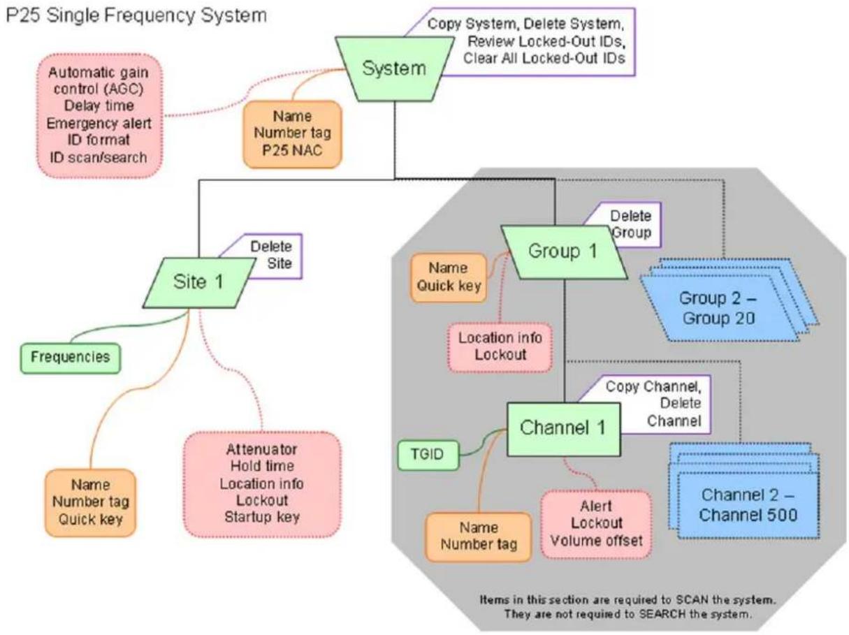
flowchart
graph TD
    A["System"] --> B["Site 1"]
    A --> C["Copy System, Delete System, Review Locked-Out IDs, Clear All Locked-Out IDs"]
    A --> D["Automatic gain control (AGC) Delay time Emergency alert ID format ID scan/search"]
    A --> E["Name Number tag P25 NAC"]
    A --> F["Delete Site"]
    F --> G["Frequencies"]
    F --> H["Attenuator Hold time Location info Lockout Startup key"]
    A --> I["Group 1"]
    I --> J["Delete Group"]
    I --> K["Channel 1"]
    K --> L["Copy Channel, Delete Channel"]
    K --> M["Channel 2 – Channel 500"]
    K --> N["TGID"]
    K --> O["Location info Lockout"]
    K --> P["Alert Lockout Volume offset"]
    style A fill:#99ccff,stroke:#333
    style B fill:#ffcccc,stroke:#333
    style C fill:#ffcccc,stroke:#333
    style D fill:#ffcccc,stroke:#333
    style E fill:#ffcccc,stroke:#333
    style F fill:#ffcccc,stroke:#333
    style G fill:#ffcccc,stroke:#333
    style H fill:#ffcccc,stroke:#333
    style I fill:#ccffcc,stroke:#333
    style J fill:#ccffcc,stroke:#333
    style K fill:#ccffcc,stroke:#333
    style L fill:#ccffcc,stroke:#333
    style M fill:#ccffcc,stroke:#333
    style N fill:#ccffcc,stroke:#333
    style O fill:#ccffcc,stroke:#333
    style P fill:#ccffcc,stroke:#333
UBCD396XT
17. Radio Systems Overview
There are two basic types of radio systems: conventional systems and trunked systems.
Conventional radio systems
In a conventional radio system, each group of users is assigned one (for simplex systems) or two frequencies (for repeater systems). For example, the police in your area might operate on 460.500 MHz, the fire department on 154.445 MHz, the highway department on 37.900 MHz, etc. All transmissions from each group always go out on the same frequency--the police won't randomly switch to 500.000 MHz, for instance.
Since each group always stays on the same frequency and frequencies never overlap, it's very easy to follow conversations on conventional systems: when your scanner stops on a frequency, you usually know who it is, and more importantly, you can stop on a channel and listen to an entire conversation.
Up until the late 1980s, this was the primary way that radio systems operated. Some examples of conventional radio systems are
- Aircraft
- Amateur radio
• AM CB/UHF CB users - Small, private radio systems
Trunked radio systems
Several major trends have converged that have resulted in agencies moving to more efficient trunked radio systems:
- Higher levels of radio usage has meant that there aren't enough individual frequencies available to allow every group to have their own frequency.
- Technology advances have brought down the overall cost and complexity of implementing a trunked radio system while increasing the features available to the agency and individual radio users.
- Roll-out of major statewide trunked systems makes it easier for even small agencies to piggy back onto the larger system for less cost than replacing existing systems.
UBCD396XT
Trunked system basics
There are three major elements common to most trunked systems:
System Controller
The system controller is a special computer that assigns voice channels to users as they key up their radio. The controller is the brains behind the trunking system.
Voice Frequency Pool
The voice frequency pool is a selection of radio frequencies available to the system controller for assigning voice traffic. By assigning voice frequencies to channels only as they are needed, a trunked system can support many more channels than it actually has frequencies.
Talk Group IDs
A Talk Group ID identifies which user or agency has been assigned a particular voice frequency at any particular moment. The Talk Group ID is essentially the user's "channel": since each voice frequency is used over and over by all the agencies on the system, trunked systems rely on the Talk Group ID to identify which particular user or agency is talking.
How a trunked system works
A typical communication on a trunked system goes something like this:
-
A user selects the channel they want to communicate on and presses the PTT button on the side of their radio.
-
This sends a channel request message to the controller that the user wants to start a transmission on the Talk Group ID (the channel) that they selected.
-
The controller locates an unused voice frequency and assigns it to that Talk Group ID.
-
The controller then sends out a channel grant message to all radios on the system so everyone knows where to find the voice channel for that Talk Group.
-
At this point, the original user's radio beeps, and the user can begin their transmission. While this sounds complicated, in real life this process takes about half a second (sometimes less).
UBCD396XT
When the user releases the PTT button, the controller releases the voice frequency from its Talk Group ID assignment, leaving the frequency free for the next user that becomes active.
A real life example
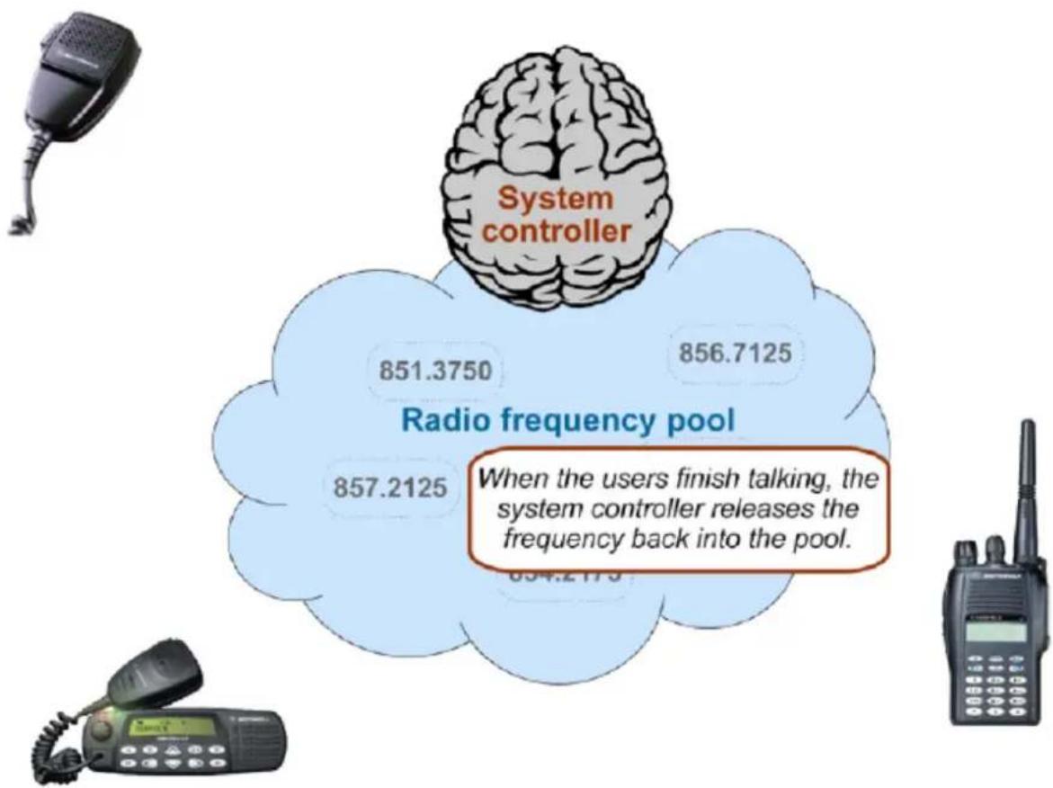
A typical 20-frequency trunked system can support hundreds of channels. For example, the Fort Worth system includes over 400 channels providing communication support for Fort Worth agencies (Police, Fire and Ambulance) and agencies in the surrounding cities of Kennedale, North Richland Hills, Forest Hill, Haltom City and Richland Hills. In addition, the same system also supports the Tarrant County Sheriff and Texas Christian University.
Before moving to the trunked system, the Police had only 6 channels (North, South, East, West, Information, and Tactical). Since moving to the trunked system, they are now able to provide 11 channels for North Side PD alone: a main dispatch channel, three talkaround channels, a supervisor channel, a bike patrol channel, and several community patrol channels. Other police districts have similar channel requirements, and now special operations teams such as SWAT, Narcotics, and Traffic each have one or more dedicated channels for their use as well.
UBCD396XT
18. Deciphering Trunked Systems
Before you program a trunked system
To the average radio user, the complexity of a trunked system is invisible. Their radio is programmed up at the radio shop. They can still easily select who they need to communicate with by selecting a channel on their two-way. They can even directly call other radio users without tying up a dispatch channel — something they could never do before. As a scanner user, on the other hand, you need to know the different types of trunking systems in use, what options are available on each system, and three key pieces of information about any trunking system before you start any actual programming:
- System Type
- System Frequencies
• IDs of the Talk Groups you want to hear
This information is usually available from the online database at www.RadioReference.com.
System Type
There are five major types of scannable systems; some of these also have subtypes. (In the RadioReference database, you can generally determine the radio system type by looking at the line labeled System Type at the top of the screen.)
P25 Systems
These are identified in the RadioReference database as Project 25 Standard. If the System Type line says anything else, then it is not a P25 system (even though it might have some P25 channels).
LTR Systems
These systems are identified as LTR Standard in the system type.
Motorola Systems
There are several subcategories of Motorola systems, but they will all have some form of Motorola in the system type: Motorola Fleetnet, Motorola Smartnet, Motorola Smartzone, etc. Once you have identified that it is a Motorola system, you can check the system frequencies to confirm its subtype:
- Motorola 800: all of the frequencies are in the 800 MHz range
- Motorola 900: all of the frequencies are in the 900 MHz range
- Motorola UHF: all of the frequencies are between 400 and 512 MHz
UBCD396XT
- Motorola VHF: all of the frequencies are between 100 and 200 MHz.
EDACS Systems
There are three subtypes of EDACS systems:
• EDACS Wide: identified as EDACS Standard in the system type.
• EDACS Narrow: identified as EDACS Narrowband in the system type.
- EDACS SCAT: identified as EDACS Scat in the system type (these systems operate on a single frequency).
Conventional Systems
This fifth type of scannable system is a general catchall for all non-trunked systems. See section on Conventional Systems for more information.
Non-scannable Systems
There are several system types that cannot be monitored with a scanner, either because the systems use proprietary digital formats that are not licensable by scanner manufacturers, or because the systems are not in wide enough use to make it cost-effective for manufacturers to develop a scanner that can monitor them. These non-scannable systems are identified in the system type as:
- LTR Passport
- OpenSky Standard
- MPT1327
- Tetra
System Voice
System Voice summarizes the kinds of voice modulation used on the system. You'll find the following voice types:
- Analog (can be heard with any trunking scanner)
- APCO-25 (can be heard with a digital scanner)
• ProVoice (cannot be heard by any scanner)
• VSELP (cannot be heard by any scanner)
The system voice also tells us when digital channels are mixed in with analog channels on the same system. Unfortunately, this means the system voice line can cause a lot of confusion. Just remember: system voice does not define the system type.
UBCD396XT
For example, APCO-25 can be used as a voice type on a Motorola system that is not actually a P25 system. When we're trying to determine whether a system is a P25 system, we need to ignore the System Voice line and focus on the System Type line. If there is P25 Voice on a non-P25 system, the scanner can sort this out while scanning.
System Frequencies
The system frequencies section in the database lists all the frequencies used by the system. For Motorola and P25 systems, you will need to program only the system control channel frequencies for primary control channels and for alternate control channels in the database.
For EDACS and LTR systems, you will need to program all the listed frequencies and their associated LCN. Some systems have multiple sets of frequencies. These are called multi-site systems: each set of frequencies corresponds to a different physical antenna site.
Talk Group IDs (Channels)
The Talk Group information section shows the different channels on the system and which agency uses them. You'll need to go through the list and make a note of the channels you want to hear. Then you can start thinking about how you want to organize those channels.
(One of the great features available to subscribers on RadioReference is the ability to tag channels directly on the site and print out a nicely-formatted hardcopy of each system. It makes this task much, much easier.)
UBCD396XT
19. Location-based Scanning
Location-based scanning allows you to control which sites and channel groups are scanned based on your exact location. This frees you from having to manually enable and disable systems or channel groups as you change location.
To use Location-Based scanning, you need to have the following:
- the location for the center point for each site or channel group you want to control
- the radius or distance from the center point you want to set as the range for each site or channel group
- if you are scanning while traveling, you may want to include the heading (direction) of travel
- some type of mapping method. If you don't want to use paper maps, you might try a mapping software (such as Microsoft® Streets and Trips or Delorme® Street Atlas) that allows you to draw markings and overlays on maps.
- a GPS receiver with a serial data output (NMEA)
There are many different approaches you can use to determine where to place a center point for a system/ site or channel group. The two most common are the geopolitical approach and the antenna-centric approach. For large trunked systems, you may find that a combination of these two approaches works best.
The Geopolitical Approach
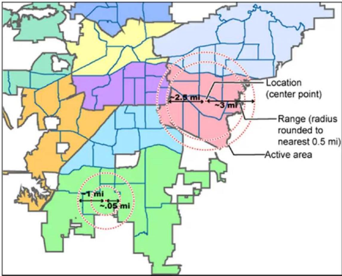
With the geopolitical approach, you want the scanner to turn on the site or channel group at the limit of relevance rather than reception. This approach is useful for scanning targets that have a well-defined jurisdiction and their transmission are only relevant when you are within that jurisdiction.
To use the geopolitical approach, find the geographical center of the scanning target's territory (whether city, county, district, precinct, or other agency jurisdiction), and set these coordinates as your center point location. Then, adjust the range or radius to cover the boundaries of that target.
To use this method, use your chosen mapping application to zoom out so that the entire target is visible, then, draw a circle that just covers the targets boundaries. Adjust the size of the circle to the nearest 12 mile increment.
Depending on the shape of the territory, you may have to choose between a lot of overlap or not covering the entire area: jurisdiction, you might end up with a large amount of overlap. You'll have to decide which radius that best suits your application.
UBCD396XT
For example, if your territory is a city, you'll have a lot of "extra" area if you use one single location:
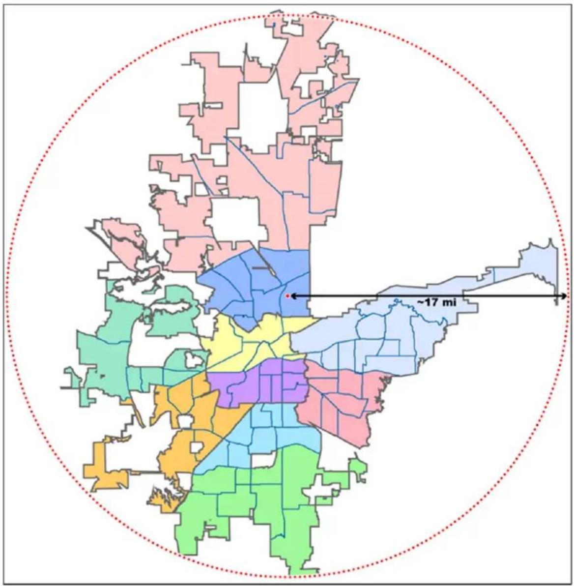
geo
| Region Color | Description | | ------------ | ------------------ | | Green | Central region | | Yellow | Northeastern region | | Purple | South-central region| | Pink | Northeastern region | | Light Blue | Northeastern region | | Light Blue | West-central region | | Light Blue | East-central region | | Light Blue | West-central region | | Light Blue | Central region | | Light Blue | Northeastern region | | Light Blue | West-central region | | Light Blue | East-central region | | Light Blue | West-central region | | Light Blue | Central region | | Orange | Central region | | Orange | Northeastern region | | Orange | West-central region | | Orange | East-central region | | Orange | West-central region | | Orange | Central region | | Orange | Northeastern region | | Orange | West-central region | | Orange | Central region | | Orange | Northeastern region | | Orange | Central region | | Orange | Northeastern region | | Orange | Central region | | Orange | Northeastern region | | Orange | Central region | | Orange | Northeastern region | | Orange | Central region | | Orange | Northeastern region | | Orange | Central region | | Orange | Northeastern region | | Orange | Central region | | Orange (Red) | Central region | | Orange (Red) | Northeastern region | | Orange (Red) | West-central region | | Orange (Red) | West-central region | | Orange (Red) | East-central region | | Orange (Red) | West-central region | | Orange (Red) | East-central region | | Orange (Red) | West-central region | | Orange (Red) | East-central region | | Orange (Red) | West-central region | | Orange (Red) | East-central region | | Orange (Red) | West-central region | | Orange (Red) | Central region | | Orange (Red) | Northeastern region | | Orange (Red) | West-central region | | Orange (Red) | West-central region | | Orange (Red) | East-central region | | Orange (Red) | West-central region | | Orange (Red) | East-central region | | Orange (Red) | West-central region | | Orange [Green] | Central region | | Orange [Green] | Northeastern region | | Orange [Green] | West-central region | | Orange [Green] | West-central region | | Orange [Green] | East-central region | | Orange [Green] | West-central region | | Orange [Green] | East-central region | | Orange [Green] | West-central region | | Orange [Green] | Central region | | Orange [Green] | Northeastern region | | Orange [Green] | West-central region | | Orange [Green] | West-central region | | Orange [Green] | East-central region | | Orange [Green] | West-central region | | Orange [Green] | East-central region | | Orange [Green] | West-central region, Central region (Orange) | | Orange [Green] | Orange | | Orange [Green] | Orange | | Orange [Green] | Orange | | Orange [Green] | Orange | | Orange [Green] | Orange | | Orange [Green] | Orange | | Orange [Green] | Orange | | Orange [Green] | Orange | | Orange [Green] | Orange | | Orange [Green] | Orange | | Orange [Green] | Orange, Central region| | Orange [Green] | Orange, Central region| | Orange [Green] | Orange, Central region| | Orange [Green] | Orange, Central region| | Orange [Green] | Orange, Central region| | Orange [Green] | Orange, Central region| | Orange [Green] | Orange, Central region| | Orange [Green] | Orange, Central region| | Orange [Green] | Orange, Central region| | Orange (Orange)| Orange, Central region| | Orange (Orange)| Orange, Central region| | Orange (Orange)| Orange, Central region| | Orange (Orange)| Orange, Central region| | Orange (Orange)| Orange, Central region| | Orange (Orange)| Orange, Central region| | Orange (Orange)| Orange, Central region| | Orange (Orange)| Orange, Central region| | Orange (Orange)| Orange, Central region| | Orange (Orange)| Red, Central region | | Orange (Orange)| Red, Central region | | Orange (Orange)| Red, Central region | | Orange (Orange)| Red, Central region | | Orange (Orange)| Red, Central region | | Orange (Orange)| Red, Central region | | Orange (Orange)| Red, Central region | | Orange (Orange)| Red, Central region | | Orange (Orange)| Red, Central region | | Orange (-17 mi)| Red, Central region | | Red | ~17 mi |On the other hand, if you sub-divide the area, you may end up with areas that are not covered:
UBCD396XT
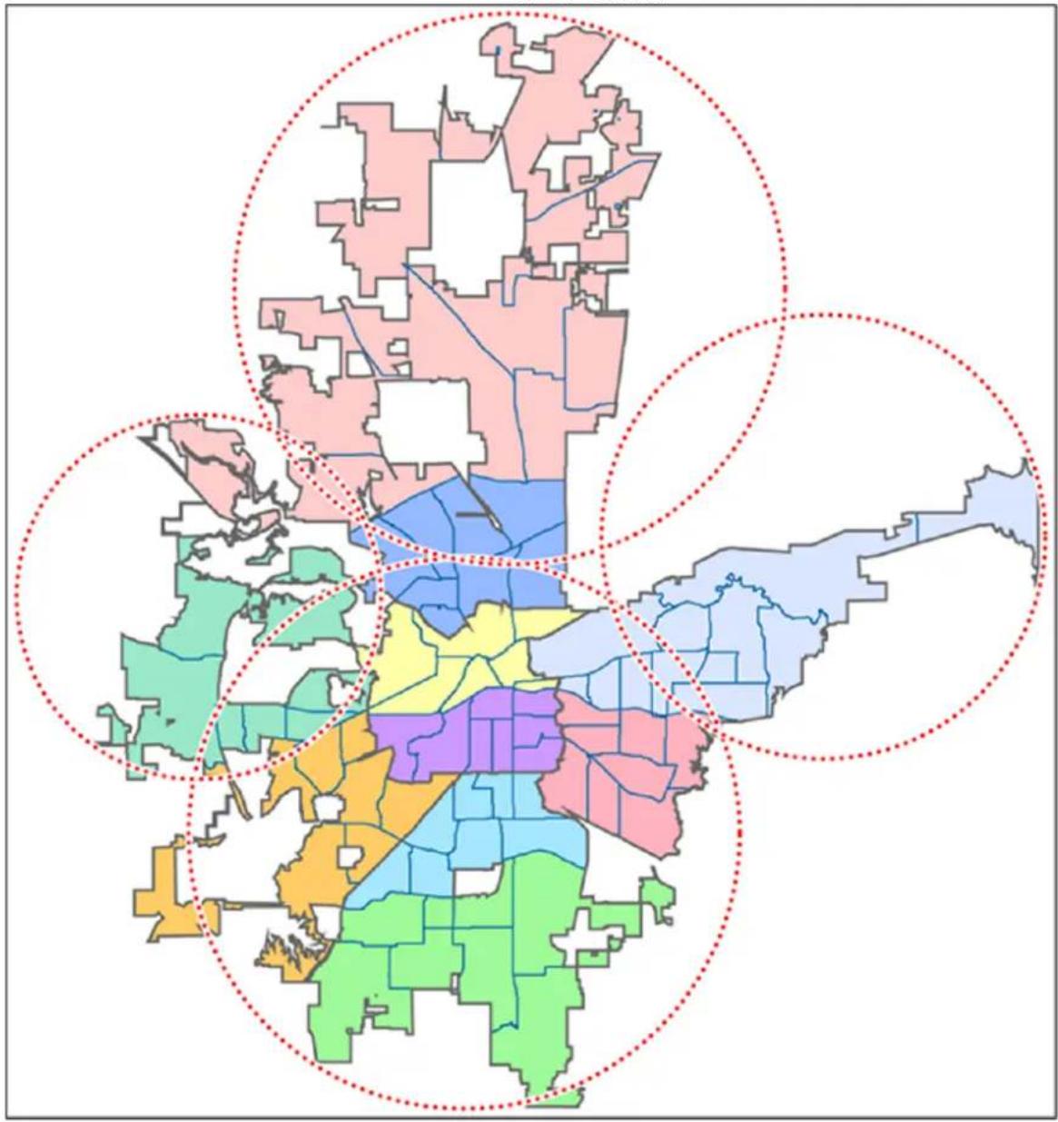
geo
| Region | Color Zone Description | |--------|--------------------------| | North Central | Pink (High), Blue (Medium), Light Blue (Low), Yellow (Medium), Green (Low) | | Northeast | Light Blue | | Southeast | Light Blue | | Midwest | Yellow | | Southwest | Light Blue | | West Coast | Light Blue | | East Coast | Light Blue | | Northwest | Light Blue | | Mountain West | Light Blue | | Central Plains | Light Blue | | Coastal Plains | Light Blue | | Coastal Heights | Light Blue | | Coastal Valley | Light Blue | | Coastal Forest | Light Blue | | Coastal Urban | Light Blue | | Coastal Suburbs | Light Blue | | Coastal Towns | Light Blue | | Coastal District | Light Blue | | Coastal District | Dark Blue | | Coastal District | Dark Blue | | Coastal District | Dark Blue | | Coastal District | Dark Blue | | Coastal District | Dark Blue | | Coastal District | Dark Blue | | Coastal District | Dark Blue | | Coastal District | Dark Blue | | Coastal District | Dark Blue | | Coastal District | Dark Blue | | Coastal District | Dark Blue | | Coastal District | Dark Blue | | Coastal District | Dark Blue | | Coastal District | Dark Blue | | Coastal District | Dark Blue |UBCD396XT
The Antenna-Centric Approach
Using an antenna-centric approach, you set the physical antenna location as the system/sites center point and the antenna's actual reach as the range.
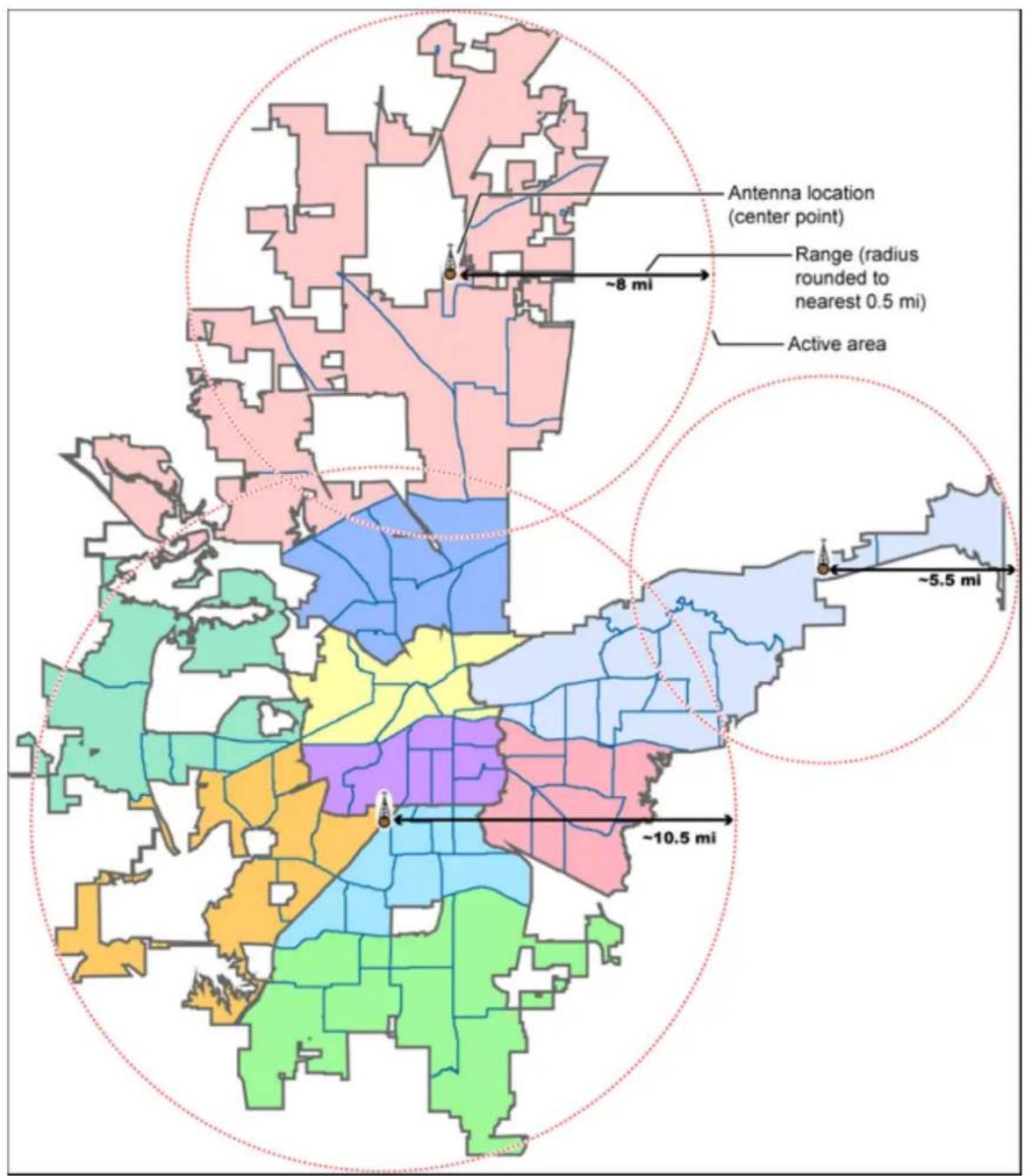
Combining for Efficiency
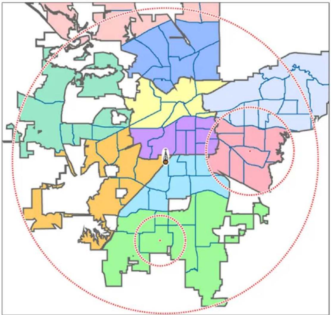
Because many trunked systems have both multiple antenna sites and multiple agencies with differing geographic boundaries, you may want to combine the approaches:
-
Use the antenna centric approach at the site level: set the geographic coordinates of the antenna as the central location for each site.
-
Use the geopolitical approach at the channel group level. Within the same system, set up a channel group for each agency, and set the central point of the agency territory as the group location.
With both approaches combined into a single system, the scanner will now seamlessly switch between antenna sites as needed to keep the scanner tuning only to those sites you can receive well, and will also turn channel groups on and off as you relocate to different jurisdictions.
UBCD396XT
See Also
Section on Connecting a GPS receiver
Section on Programming locations
20.NumberTags
- Number Tags let you quickly navigate to a specific system or channel.
- You can assign Number Tags at the system level (System Number Tag, or SNT), at the channel level (Channel Number Tag, or CHNT), or at both levels.
- You can assign an SNT to the temporary system Close Call Hits that is created during Close Call searches. This system and its SNT operate like any other system.
- You can assign Number Tags to service searches and custom search ranges. These search Number Tags operate like regular SNTs.
Programming Number Tags
Assigning an SNT
• SNTs can range from 0 to 999.
- Systems can have the same SNT, but you will get a warning when you create multiples. (This includes SNTs assigned to the Close Call Hits system or any search ranges.)
To a system:
- Open the Program System menu.
- Select the system you want to assign the number tag to.
- Select Edit Sys Option, then select Set Number Tag.
- Enter the number tag you want to use for this system.
To the Close Call Hits system :
- Open the Close Call menu.
- Select Hits with Scan, then select Set Number Tag.
- Enter the number tag you want to use for the Close Call Hits system.
To a service search range:
- Open the Search for... menu.
- Select Edit Service, then select the service search range you want to assign the number tag to.
UBCD396XT
- Select Search with Scan, then select Set Number Tag.
- Enter the number tag you want to use for this search range.
To a custom search range:
- Open the Search for... menu.
- Select Edit Custom, then select the custom search range you want to assign the number tag to.
- Select Search with Scan, then select Set Number Tag.
- Enter the number tag you want to use for this custom search range.
Assigning a CHNT
- You can assign CHNTs to channels even if the system does not have an assigned SNT. However, without an SNT, you can only navigate to these channels from within that system itself.
-
CHNTs can be duplicated within their own system, but you will see a warning when you create multiples.
• CHNTs can range from 0 to 999. -
Open the Program System menu.
- Select the system containing the channel you want to assign the number tag to.
- Select Edit Group, then select the channel group you want.
- Select Edit Channel, then select the channel you want to assign the number tag to.
- Select Set Number Tag.
- Enter the number tag you want to use for this channel.
Using Number Tags
| To navigate directly to: | Key Sequence Example | |
| A system or search range | 1. Tap HOLD.2. Enter the SNT + •.3. Tap MENU. | If the SNT is 4, enter HOLD / 4 / • / MENU. |
| A channel in the current system | 1. Tap HOLD.2. Enter the CHNT.3. Tap MENU. | If the CHNT is 27, enter HOLD / 27 / MENU. |
| A channel in a different system | 1. Tap HOLD.2. Enter the SNT followed by the decimal point.3. Enter the CHNT.4. Tap MENU. | If the SNT is 4 and the CHNT is 27, enter HOLD / 4 / • / 27 / MENU. |
Notes:
- If two systems have the same SNT, they will be selected in sequence (i.e. the first time you select the SNT, the scanner will go to the first system assigned with that SNT; if you select the same SNT again, it will go to the 2nd system assigned with that SNT, and so on).
- If two channels in the same system have the same CHNT, they will be selected in sequence (i.e. the first time you select the CHNT, the scanner will go to the first channel in that system assigned with that CHNT; if you select the same CHNT again, it will go to the 2nd channel assigned with that CHNT, and so on).
21. QuickKeys
- Quick Keys let you enable or disable systems and channel groups during a scan. Disabled systems and channel groups are ignored during scans.
- You can assign Quick Keys at the system/site level (System/site Quick Key or SQK), at the channel group level (Group Quick Key, or GQK), or at both levels.
- You can assign an SQK to the temporary system Close Call Hits that is created during Close Call searches. This system and its SQK operate like any other system.
- You can assign Quick Keys to service searches and custom search ranges. These search Quick Keys operate like regular SQKs.
Programming Quick Keys
Assigning an SQK
- Multiple systems, sites, and search ranges can share the same SQK.
- All systems and sites assigned to the same SQK will be enabled (or disabled) when you enter the Quick Key.
• SQKs range from 0 to 99.
To a conventional system:
- Open the Program System menu.
- Select the system you want to assign the Quick Key to.
- Select Edit Sys Option, then select Set Quick Key.
- Enter the Quick Key you want to use for this system.
To a trunked system:
- Open the Program System menu.
- Select the system you want to assign the Quick Key to.
- Select Edit Site, then select the site you want.
- Select Set Quick Key, then enter the Quick Key you want to use for this site.
To the Close Call Hits system :
- Open the Close Call menu.
- Select Hits with Scan, then select Set Quick Key to.
- Enter the Quick Key you want to use for the Close Call Hits system.
UBCD396XT
To a service search range :
- Open the Search for... menu.
- Select Edit Service, then select the service search range you want to assign the Quick Key to.
- Select Search with Scan, then select Set Quick Key.
- Enter the Quick Key you want to use for this search range.
To a custom search range :
- Open the Search for... menu.
- Select Edit Custom, then select the custom search range you want to assign the Quick Key to.
- Select Search with Scan, then select Set Quick Key.
- Enter the Quick Key you want to use for this custom search range.
Assigning a GQK
- All channels in the channel group will be enabled (or disabled) when you enter the GQK.
- Multiple channel groups in the same system can share the same GQK. However, all of these channel groups will be enabled (or disabled) when you enter the GQK from within that system.
- You can assign GQKs to channel groups even if their system does not have an assigned SQK.
-
You can only use GQKs within the current system: the GQK will not affect a channel group in another system.
• GQKs range from 0 to 9. -
Open the Program System menu.
- Select the system containing the channel group you want to assign the Quick Key to.
- Select Edit Group, then select the channel group you want.
- Select Set Quick Key, then enter the Quick Key you want to use for this channel group.
Using Quick Keys
- Quick Keys only work in Scan mode.
UBCD396XT
- Entering the Quick Key toggles the enabled/disabled state of the system/site/search range or channel group (i.e., if the system is currently enabled, entering the Quick Key will disable it, and vice-versa).
To use SQK 0 through 9
- Enter Scan mode.
- Tap the number key that matches the SQK. (For example, if the SQK is 4, just enter 4.)
- Any systems, sites, or search ranges assigned to this SQK become disabled. (If they were already disabled, they become enabled.)
To use SQK 10 through 99
- Enter Scan mode.
- Tap the decimal point (./NO), then enter the SQK. (For example, if the SQK is 32, enter./NO / 32.)
- Any systems, sites, or search ranges assigned to this SQK become disabled. (If they were already disabled, they become enabled.)
To use a GQK
- Enter Scan mode.
- Go to the system that contains the channel group you want to enable or disable.
- Tap FUNCTION, then tap the number key that matches the GQK. (For example, if the GQK is 7, enter FUNCTION / 7.)
- Any channel groups assigned to this GQK within the current system only become disabled. (If they were already disabled, they become enabled.)
22. SearchKeys
The scanner has three Search Keys that you can assign to a special search range; the Search Keys are set to number keys 1, 2, and 3:
Search Key 1
Search Key 2
Search Key 3
Programming Search Keys
- Open the Search for... menu.
- Select Set Search Key, then select the search key you want to program.
- Select the search range you want to assign to this Search Key. Choose one of the pre-programmed service search ranges, one of the 10 custom search ranges, a Tone-Out search, or a Band Scope search.
Using Search Keys
To start the search assigned to a Search Key, FUNCTION + tap that Search Key. For example, to start the search assigned to Search Key 2, FUNCTION + tap 2.
(You can't use the Search Keys when the scanner is in Scan mode or GPS mode.)
If the Search Key you select starts a Tone-Out search, the scanner switches to Tone-Out mode and searches the most-recently-used Tone-Out channel (out of the 10 available). If you want to search a different Tone-Out channel, use the SELECT-VOLUME-SQUELCH knob on handheld models to select the Tone-Out channel you want to use.
UBCD396XT
23. Programming locations
To use Location-based Scanning with a particular system, you will need to program your scanner with the geographic coordinates you want to use for each site or channel group. You can also program your scanner to alert you when you approach particular locations.
Programming a location for a site
Each system site can have separate location information.
- Open the Program System menu.
- Select the system you want to program for location based scanning.
- Select Edit Site, then select the first site you want to assign a location to.
- Select the Set LocationInfo menu and enter the latitude, longitude, and range for this site.
- Change the Set GPS Enable field to On.
- Go back to the Edit Site menu and repeat these steps with any other sites you want to program for this system.
Programming a location for a channel group
Each channel group in a system can have separate location information.
- Open the Program System menu.
- Select the system you want to program for location based scanning.
- Select Edit Group, then select the first channel group you want to assign a location to.
- Select the Set LocationInfo menu and enter the latitude, longitude, and range for this site.
- Change the Set GPS Enable field to On.
- Go back to the Edit Group menu and repeat these steps with any other groups you want to program for this system.
Remember: You have to turn on Set GPS Enable before the location information can affect that site or channel group.
Programming general locations
You can program general locations (i.e., locations that are not associated with a site or channel group). There are three types of general locations:
- points of interest (POI)
UBCD396XT
• intersections ( Dangerous Xing )
- roads (Dangerous Road)
You can program the scanner to alert you when you come within a designated distance of that location.
To create a new location
- Open the Program Location menu.
- Select the type of location you want to create.
- Select New Location to create a new location of this type.
- If you want to create a different type of location, go back to the Program Location menu and select that location type.
- If you want to change the default location name, select Edit Name and enter a new name.
- Select Set LocationInfo and enter the latitude and longitude for this location.
- Select Set Range and enter the distance from this location you want the scanner to alert you.
- Choose the Alert Tone and Alert Light you want the scanner to use when you come within range of this location.
For Dangerous Xing and Dangerous Roads only
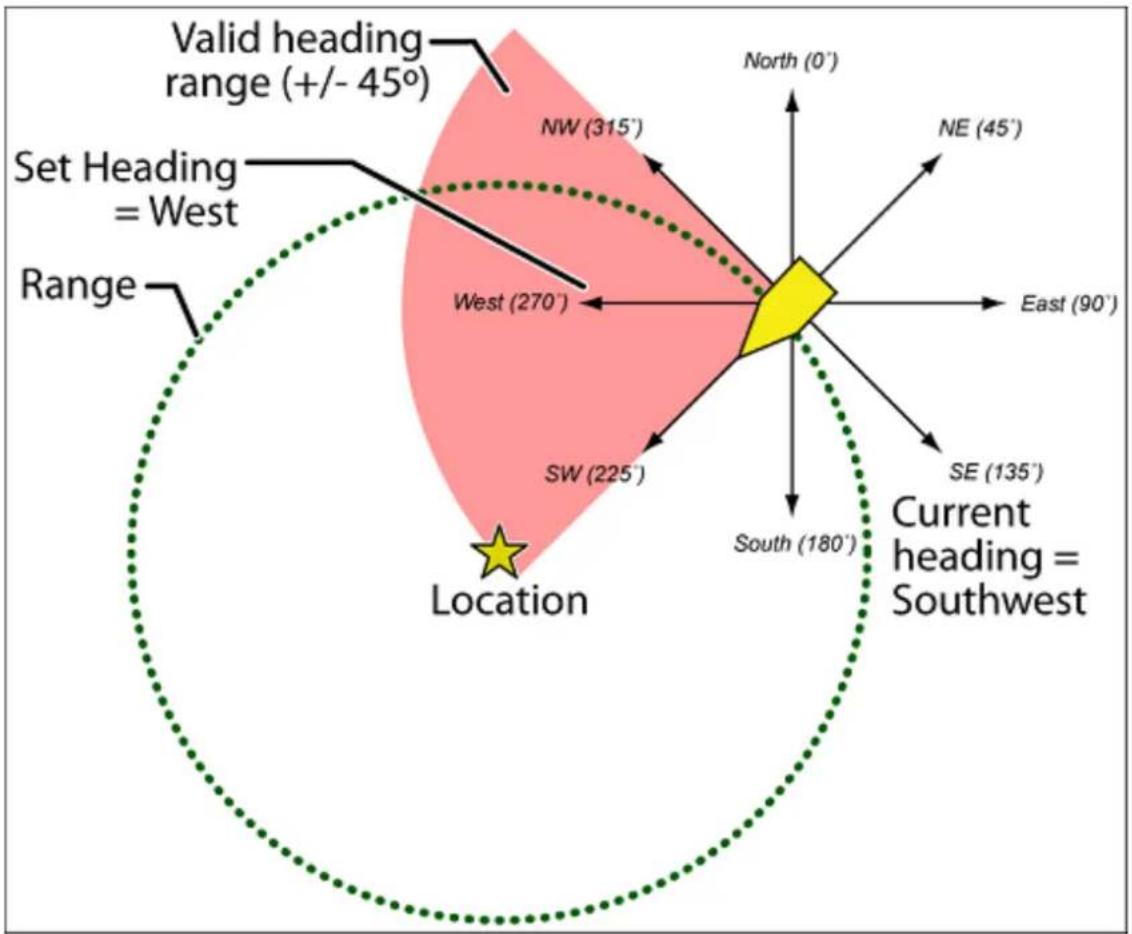
radar
| Direction | Value | | --------- | --------- | | North | 0° | | NE | 45° | | East | 90° | | SE | 135° | | South | 180° | | SW | 225° | | SW (270°) | 270° | | SW (315°) | 315° | | Set Heading = West | - | | Valid heading range (+/- 45°) | - | | Current heading = Southwest | - |In addition to range, you can specify a heading and a speed limit for these types of locations:
- If you set a speed limit, the scanner will only trigger an alert when you are within the location's range and your current speed is over the programmed speed limit.
- If you set a heading, the scanner will only trigger an alert when you are within the location's range and your current heading is +/- 45 degrees from the programmed heading. (For example, if you set the heading as North, the scanner will trigger an alert if your current heading is North-east but not if your current heading is due East.)
Edit an existing location
-
Open the Program Location menu.
-
Select the type of location you want to edit; the scanner lists the existing locations of that type in alphabetical order.
-
Select the location you want to edit, then change any of the location settings you want.
Your scanner can trigger alerts for several different events. The table below shows the different alerts and how to program them:
| To sound an alert when Follow these steps | |
| A channel becomes active | Edit the channel properties (Edit Channel#Set Alert):1. Go to the Program System menu and select the system that contains the channel you want set the alert for.2. Select Edit Group, then select the group you want.3. Select Edit Channel, then select the channel you want to set the alert for.4. Select Set Alert.5. Choose the Alert Tone and Alert1. Light you want the scanner to use. |
| An active Talk Group on a system contains an emergency flag | Edit the system properties (Edit Sys Option#Emergency Alert):1. Go to the Program System menu and select the system you want set the alert for.2. Select Edit Sys Option, then select2. Emergency Alert.3. Choose the Alert Tone and Alert4. Light you want the scanner to use. |
| The scanner detects a Close Call hit | Edit the Close Call properties:1. Go to the Close Call menu.2. Select Set CC Alert .3. Choose the Alert Tone and Alert Light you want the scanner to use.4. For Close Call Alerts, you can also have the scanner pause before it resumes searching. Select Set CC Pause to activate this feature. |
| The scanner gets a hit on a Tone-Out channel | Edit the Tone-Out channel properties:1. Go to the Tone-Out for... menu.2. Select Tone-Out Setup, then select the |
UBCD396XT
| Tone-Out channel you want to set the alert for.3. Select Set Alert.4. Choose the Alert Tone and Alert Light you want the scanner to use. | |
| You approach a particular locationPoint of Interest (POI)Dangerous RoadDangerous Intersection (Dangerous Xing) | Edit the location properties:1. Go to the Program Location menu and select the type of location you want set the alert for.2. Select the particular location.3. For a POI, select Set Alert , then choose the Alert Tone and the Alert Light you want to use.4. For a Dangerous Road or Xing, the alert tone is preset. Select the Alert Volume and the Alert Light you want to use. |
UBCD396XT
25. Using Quick Keys, Startup Keys, and Search Keys
The different shortcut keys have different functions:
Quick Keys
- Quick keys let you enable and disable systems and channel groups (disabled systems and channel groups are ignored during scans).
- You must be in Scan mode to use Quick Keys.
- System Quick Keys (SQKs) let you enable or disable systems, sites or search ranges: just enter the SQK from the number pad.
- Group Quick Keys (GQKs) let you enable or disable channel groups inside the current system: Tap FUNCTION, then enter the GQK from the number pad.
Startup Keys
- Startup Keys let you lock and unlock several systems, sites, and search ranges all at the same time.
- When you activate a Startup Key, the scanner unlocks all systems, sites, and search ranges that are assigned to that same Startup Key; the scanner also locks all systems, sites, and search ranges that are assigned to a different Startup Key.
- To activate a Startup Key, press & hold the number key while you power the scanner on.
Search Keys
- Search Keys let you quickly start one of 3 programmed searches.
- To start the search assigned to a Search Key, FUNCTION + tap that Search Key.
UBCD396XT
26. Tone Out mode
With the tone out feature, the scanner monitors up to 10 different channels for paging tones (two-tone sequential, single tone, and group tone). Normally, the scanner monitors each of the 10 channels in turn. However, if any tone-out channels share the same frequency, modulator, and attenuator settings, the scanner checks these channels simultaneously.
Configuring Tone Out channels
To configure Tone-Out channels:
- Go to the Tone-Out for... menu.
- Select Tone-Out Setup.
- Select the Tone-Out channel (Tone-Out 1 through Tone-Out 10) you want to configure.
- Select Set Frequencies and choose the frequencies for this channel
- Select Set Tone and program Tone A and Tone B.
- Set any of the other properties as you prefer (they aren't required).
| Required | Frequencies ( Set Frequencies)Tone A and Tone B ( Set Tones) |
| Recommended Optional | Name ( Edit Name)Automatic Gain Control ( Set Audio AGC )Delay Time ( Set Delay Time )Alert ( Set Alert) |
Using Tone-Out Mode
To start a Tone-Out search:
- Tap MENU.
- Scroll down and select Tone-Out for...
-
Select Tone-Out Standby to start the search.
-
The scanner starts searching the most recently-used Tone-Out channel (and any other Tone-Out Channels that have the same frequency).
- If you want to search a different channel, just turn the SELECT-VOLUME-SCROLL knob until you find the channel you want.
UBCD396XT
• To exit Tone-Out mode, tap SCAN.
Key operation in Tone Out Mode
- Turn the SELECT-VOLUME-SCROLL knob to change the channel.
- FUNCTION + tap MENU to go to the Tone-Out for... menu.
| Key Name(2nd operation)Action On: |  |  |  |  |
| HOLD (Close Call) | 1 (Search 1) | 2 (Search 2) | 3 (Search 3) | |
| Tap Enter | Hold mode (the scanner opens squelch). | Enter the number on the key. | ||
| FUNCTION+ Tap | Toggle Close Call modes. | Start the search range assigned to this Search Key. | ||
| FUNCTION+ Press & hold | Enter Close Call Only mode. | NA NA NA | ||
| Key Name( 2^nd operation)Action on: |  Scan (Search) Scan (Search) |  4 (IF exchange) 4 (IF exchange) |  5 (Volume offset) 5 (Volume offset) |  6 (Display mode) 6 (Display mode) |
| Tap Enter | Scan mode. | Enter the number on the key | ||
| FUNCTION+ Tap | Display the Quick Search screen (enter Search mode). | Switch to the intermediate frequency (IF). | NA NA | |
| Key Name(2nd operation)Action on: |  Lockout Lockout |  7 (Attenuation) 7 (Attenuation) |  8 (Reverse freq.) 8 (Reverse freq.) |  9 (Modulation) 9 (Modulation) |
| Tap NA | Enter the number on the key. | |||
UBCD396XT
| FUNCTION+ Tap | NA Toggle | the attenuator state for this channel. | NA Change the modulation. | |
| FUNCTION+ Press & hold | NA Toggle | the attenuator state for all signals. | NA NA | |
| Key Name(2nd operation)Action on: |  Backlight(Power, Lock) Backlight(Power, Lock) |  No (Decimal,Priority) No (Decimal,Priority) |  0 0 |  Yes (Enter,GPS) Yes (Enter,GPS) |
| Tap Turn | on the LCD backlight. | During a system message: Cancel the message and exit that screen. | Enter the number on the key. | Edit the current Tone-Out channel. |
| Press & hold | Turn the scanner on or off. | NA NA NA | ||
| FUNCTION+ Tap | Lock or unlock the keypad. | NA NA. | Enter | GPS mode. |
| FUNCTION+ Press & hold | NA NA NA | NA | ||
27. CloseCallmode
When the scanner is in Close Call mode, it performs a close call check every 2 seconds. The scanner switches to the selected bands and searches for unusually strong signals (indicating the transmitter is probably somewhere close by). After the close call check, the scanner returns to its previous function.
In Close Call Do Not Disturb mode, the scanner does not perform a Close Call check if it is already receiving an audio transmission. This prevents the audio from cutting out every 2 seconds.
In Close Call Only mode, the scanner only performs Close Call checks.
The Close Call menu lets you change the operation settings of the Close Call feature. You can change the overall Close Call options through the Srch/CloCall Opt menu.
Key operation in Close Call Only mode
- Turn the SELECT-VOLUME-SCROLL knob to resume searching.
- FUNCTION + tap MENU to go to the Close Call menu.
| Key Name(2nd operation)Action on: |  Hold (Close Call) Hold (Close Call) |  1 (Search 1) 1 (Search 1) |  2 (Search 2) 2 (Search 2) |  3 (Search 3) 3 (Search 3) |
| Tap | When the scanner detects a Close Call hit: Enter Hold mode. | Disable the Close Call band associated with this key. Tap again to enable. | ||
| FUNCTION+ Tap | Toggle Close Call mode. | Start the search assigned to this Search Key. | ||
| Key Name(2nd operation)Action on: |  Scan (Search) Scan (Search) |  4 (IF exchange) 4 (IF exchange) |  5 (Volume offset) 5 (Volume offset) |  6 (Display mode) 6 (Display mode) |
| Tap Enter | Scan mode. | Disable the Close Call band associated with this key. Tap again to enable. | ||
UBCD396XT
| FUNCTION+ Tap | Display the Quick Search screen (enter Search mode). | Switch to the intermediate frequency (IF). | NA NA | |
| Key Name(2nd operation)Action on: |  Lockout Lockout |  7(Attenuation) 7(Attenuation) |  8 (Reverse freq.) 8 (Reverse freq.) |  9(Modulation) 9(Modulation) |
| Tap Temporarily lock out the current Close Call frequency (until you turn the scanner off). | Disable the Close Call band associated with this key. Tap again to enable. | NA NA | ||
| Double tap Permanently lock out the current Close Call frequency. | NA NA NA | |||
| Press & hold Unlock allClose Call and Search frequencies. | NA NA NA | |||
| FUNCTION+ Tap | Review the list of locked out frequencies. | Toggle the attenuator state for this channel. | NA Change the modulation. | |
| FUNCTION+ Press & hold | NA Toggle the attenuator state for all signals. | Show the reverse frequency for the current frequency.(The scanner returns to the current | NA | |
UBCD396XT
| frequency when you release the key.) | ||||
| Key Name (2nd operation) Action on: |  |  |  |  |
| Backlight (Power, Lock) | No (Decimal, Priority) | NA | Yes (Enter, GPS) | |
| Tap Turn on the LCD backlight. | During a system message: Cancel the message and exit that screen. | NA When | monitoring a Close Call frequency: store the current frequency. | |
| Press & hold Turn the scanner on or off. | NA NA NA | |||
| FUNCTION + Tap | Lock or unlock the keypad. | NA NA | Enter GPS mode. | |
| FUNCTION + Press & hold | NA NA NA | NA | ||
28. Band Scope mode
Band Scope mode is a special type of Search mode where the scanner displays the strength of any signal it finds.
- In a band scope search, the scanner starts at the lowest frequency in the range and moves up the search range.
- In Max Hold Search mode, the scanner displays the strongest signal that it found.
- If you manually set the mode to NFM or FM, the scanner will not reliably detect signals that are modulated in either FMB or WFM.
To turn on Band Scope mode:
Band Scope mode is the default setting for Search Key 3. To turn on Band Scope mode, enter Search mode, then tap FUNCTION + 3 (SR3). (To change the Search Key assignment, see Search Keys#Programming Search Keys.)
Reading the display in Band Scope mode
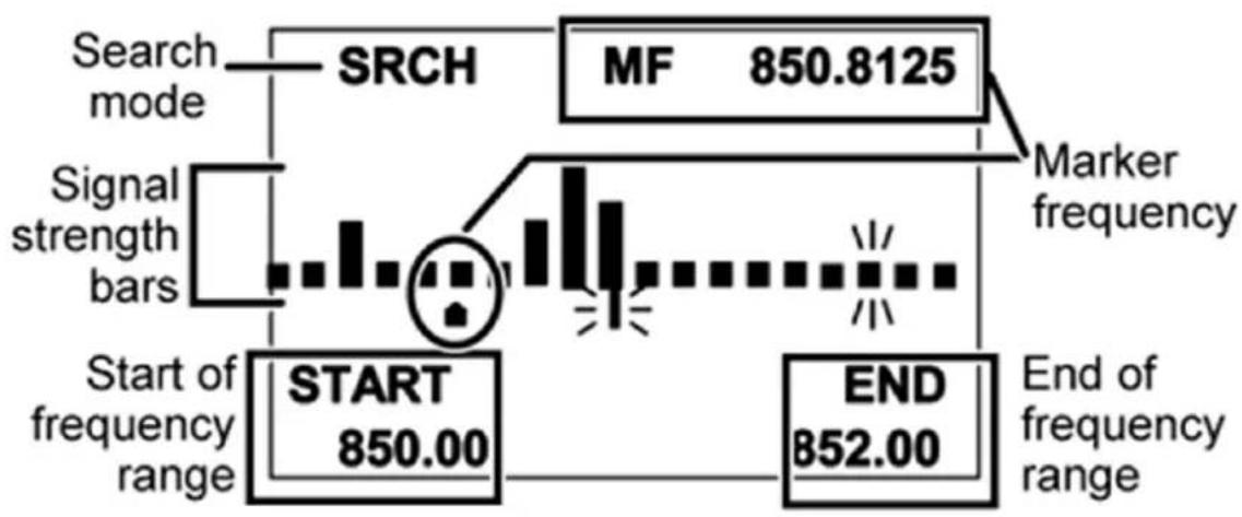
bar
| Start of frequency range | Marker frequency | MF | | ------------------------ | ---------------- | ------ | | START | 850.00 | 850.8125 | | END | 852.00 | |UBCD396XT
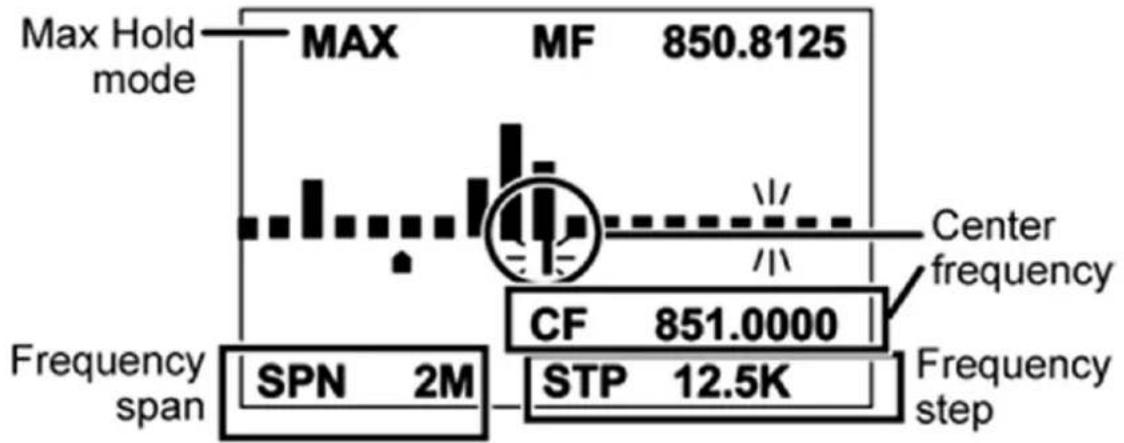
bar
| Frequency span | SPN 2M | STP 12.5K | | -------------- | ------ | --------- | | Center frequency | 851.0000 | 12.5K |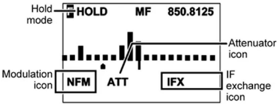
bar
| Component | Value | | ----------------- | ------- | | Hold mode | HOLD | | Modulation icon | NFM | | Modulation icon | ATT | | Modulation icon | IFX | | Attenuator icon | - | | IF exchange icon | - |Key operation in Band Scope mode
| Key Name(2nd operation)Action on: |  Hold (Close call) Hold (Close call) |  1(Search 1) 1(Search 1) |  2 (Search 2) 2 (Search 2) |  3 (Search 3) 3 (Search 3) |
| Tap Enter | Hold mode. | NA NA NA | ||
| FUNCTION+ Tap | Toggle Close Call modes. | Start the search assigned to this Search key. | ||
| FUNCTION+ Press & hold | Enter Close Call Only mode. | NA NA NA | ||
UBCD396XT
| Key Name(2nd operation)Action on: |  Scan (Search) Scan (Search) |  4 (IF exchange) 4 (IF exchange) |  5 (Volume offset) 5 (Volume offset) |  6 (Display mode) 6 (Display mode) |
| Tap Enter | Scan mode. | NA NA NA | ||
| FUNCTION+ Tap | Change the band scope search type. | Switch the Intermediate Frequency used on this Frequency. | NA NA | |
| Key Name(2nd operation)Action on: |  Lockout Lockout |  att7 (Attenuation) att7 (Attenuation) |  8 (Reverse freq.) 8 (Reverse freq.) |  9 (Modulation) 9 (Modulation) |
| Tap Press | this key to close the setting screen and return to the Normal Screen. | NA NA NA | ||
| FUNCTION+ Tap | Press this key to restart searching. | Toggle the attenuator state for the current signal. | NA Change the modulation. | |
| FUNCTION+ Press & hold | NA Toggle the attenuator state for all signals. | NA NA | ||
| Key Name(2nd operation)Action on: |  Backlight (Power, Lock) Backlight (Power, Lock) |  pHNo (Decimal, Priority) pHNo (Decimal, Priority) |  NA NA |  Yes (Enter, GPS) Yes (Enter, GPS) |
UBCD396XT
| Tap Turn on the LCD backlight. | Press this key to select the next setting item. | NA NA | ||
| Press & hold Turn the scanner on or off. | NA NA NA | |||
| FUNCTION + Tap | Lock or unlock the keypad. | NA NA | Enter GPS mode. | |
| FUNCTION + Press & hold | NA NA NA | NA |
You must have a compatible GPS receiver connected!
See Also
GPS mode is only one small part of location-based scanning. For more information on using your scanner with a GPS receiver, see the following links:
Location-based Scanning contains
- an overview of why you might want to use a GPS receiver with your scanner
- an explanation of two different approaches to location-based scanning
- some information on finding antenna locations
Programming locations contains
• details on how to program locations for systems, sites, and channels
- details on how to program Points of Interest (POI), Dangerous Roads, and Dangerous Intersections (Dangerous Xing)
• information on reviewing and editing locations
Connecting a GPS receiver contains
• details on which GPS receivers are compatible
- instructions on connecting a GPS receiver
- troubleshooting tips if you can't the receiver working with the scanner
Reading the display in GPS mode
There are several displays available in GPS mode.
Main GPS display
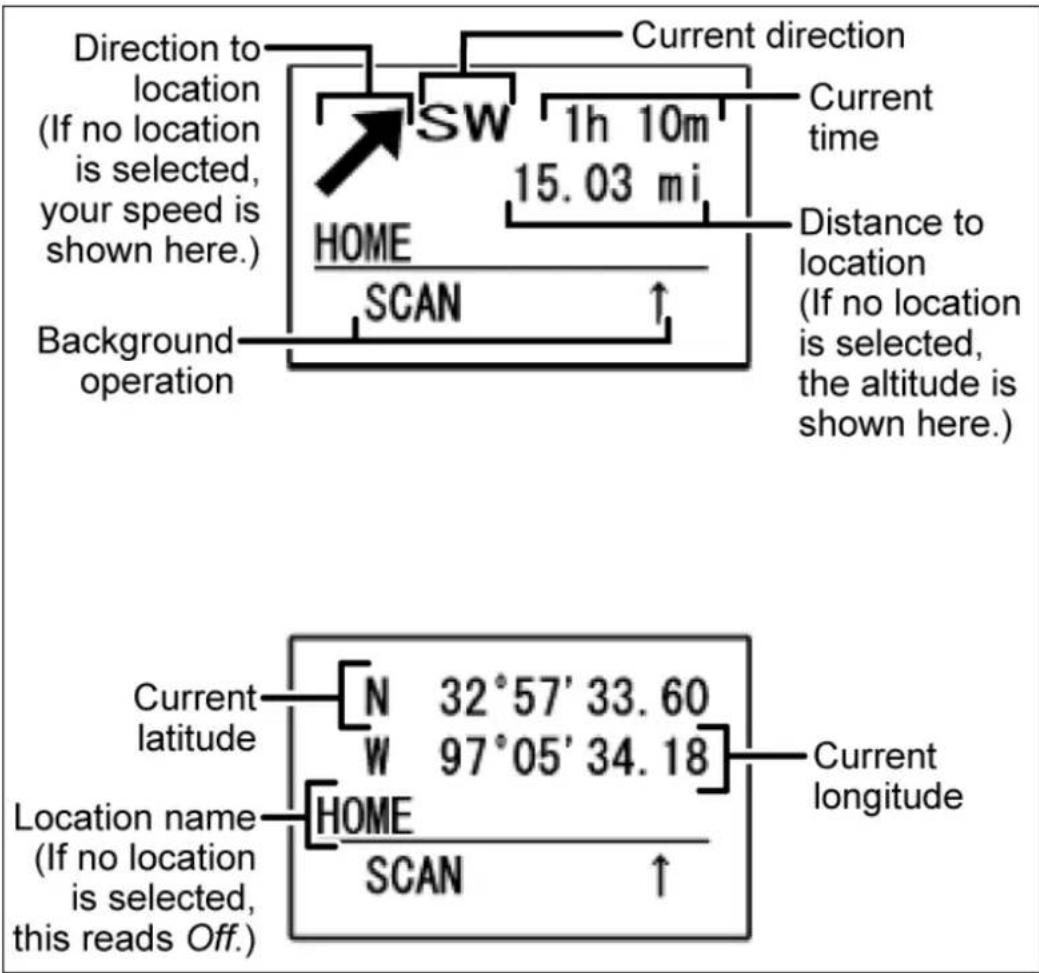
Location alert display
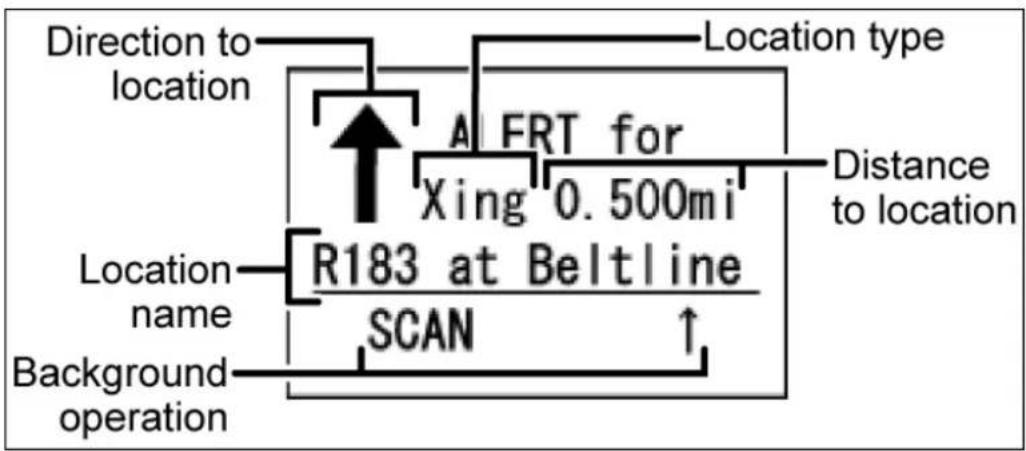
flowchart
graph TD
    A["Location type"] --> B["Direction to location"]
    B --> C["R183 at Beltline"]
    C --> D["Location name"]
    C --> E["SCAN"]
    C --> F["Background operation"]
    G["Distance to location"] --> H["A FRT for Xing 0.500mi"]
    H --> C
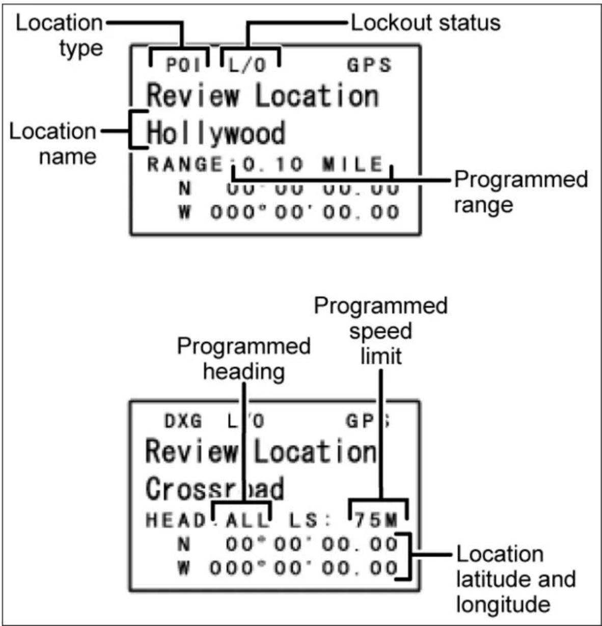
Key operation in GPS mode
| Key Name(2ndoperation)Action on: |  Hold (Close call) Hold (Close call) |  1 (Search 1) 1 (Search 1) |  2 (Search 2) 2 (Search 2) |  3 (Search 3) 3 (Search 3) |
| Tap Toggle Hold mode on the scan or search running in the background.When reviewing locations:Enter Scan Hold mode. | NA NA NA | |||
| Key Name(2nd operation)Action on: | Scan SearchScan (Search) | <4 ifx4 (IF exchange) | 5 [lvl]5 (Volume offset) | 6> disp6 (Display mode) |
| Tap Return to previous operation.When reviewing locations:Enter Scan mode. | NA NA NA | |||
| FUNCTION+ Tap | Return to previous operation.When reviewing locations:Enter Scan mode. | NA NA Cycle through | the available displays. | |
UBCD396XT
| Key Name(2nd operation)Action on: |  Lockout Lockout |  7 (Attenuation) 7 (Attenuation) |  8 (Reverse freq.) 8 (Reverse freq.) |  9 (Modulation) 9 (Modulation) |
| Tap Temporarily lockout the current Location Alert. When reviewing locations: Toggle the Lockout status of the current location. | NA NA NA | |||
| Double Tap Permanently lockout the current Location Alert. | NA NA NA | |||
| Press & hold When reviewing locations: Unlock all locations of the current type (POI, Dangerous Road or Crossing). | NA NA NA | |||
| FUNCTION+Press & hold | When reviewing locations: Unlock all locations regardless of type. | NA NA NA | ||
UBCD396XT
| Key Name(2nd operation)Action on: |  Backlight(Power, Lock) Backlight(Power, Lock) |  No (Decimal,Priority) No (Decimal,Priority) |  0 0 |  Yes (Enter,GPS) Yes (Enter,GPS) |
| Tap Turn on theLCDbacklight. | During a systemmessage:Cancel the message and exit that screen.When reviewing locations:Close the location review list. | NA Open | thelocationreviewlocation list.When reviewing locations:Edit the selected location. | |
| Press & hold Turn the scanner on or off. | NA NA NA | |||
| FUNCTION+ Tap | Lock or unlock the keypad. | NA NA NA | ||
| FUNCTION+ Press & hold | Turn the scanner on or off. | NA NA When | reviewing locations:Replace the select location's coordinates with the coordinates of your current position. | |
UBCD396XT
30. Program System
The Program System menu lets you create systems and edit existing systems. All existing systems are listed in the order they were created: select the system you want to edit, or select New System to create a new one.
When you create a new system, the scanner prompts you to select a system type; the system type you select controls what options are available for the system setup. You can't change a system type once the system is created: if you need to change the system type, delete the system and create it all over again as a new system.
The System Type options are:
☐ P25 : Use for any P25 system. When you select this system type, the scanner prompts you to choose Standard Trunk or One-Freq.
☐ MOT : Use for any Motorola system.
☐ EDCS : Use for any EDACs system. When you select this system type, the scanner prompts you to choose WIDE/NARROW or SCAT.
☐ LT : Use for any LTR system.
☐ Conventional : Use for any non-trunked system.
REMEMBER: Once you select a system type, you can't change it!
Edit Name
Enter a name or edit the existing one. Names can be 16 characters long, and they can contain upper and lower case letters, punctuation, and spaces. Turn the SELECTVOLUME-SQUELCH knob on the handheld scanners or the SCROLL / FUNCTION knob on mobile scanners to choose the character you want, then press 6 (right cursor) to move the cursor to the next character.
Edit Sys Option
This menu lets you set the options for each system.
Edit Site
(trunked systems only) This menu lets you create sites and edit existing sites. All existing sites are listed in the order they were created: select the site you want to edit, or select New Site to create a new one.
UBCD396XT
Edit Group
This menu lets you create groups and edit existing groups. All existing groups are listed in Group Quick Key order: select the group you want to edit, or select New Group to create a new one. You can have up to 20 groups in each system.
Copy System
Make a copy of this system and all its settings including all sites, groups, channels, and frequencies. The scanner prompts you to enter a new system name.
Delete System
Delete this system and all its settings; this includes sites, groups, channels, and frequencies.
New System
Create a new system.
UBCD396XT
31. Edit Sys Option
System options vary depending on the system type.
Global system options
The following options are available for all types of systems.
Set Number Tag
Assign a number to this system or channel that you can use to tune directly to a specific channel. Choose a number from 0 to 999. (For more information, see Number Tags.)
Set Delay Time
Set the number of seconds the scanner should wait after a transmission stops before moving on to the next channel. Select 0, 1, 2 (default), 5, 10, or 30 seconds.
To have scanner leave the channel after a designated number of seconds whether the transmission stops or not, select one of the negative values. Choose -10 seconds to have the scanner leave the channel after 10 seconds even if the transmission is still going on; choose -5 seconds or -2 seconds to have the scanner leave after 5 seconds or 2 seconds, respectively.
Set Audio AGC
Turn on Automatic Gain Control (AGC) for this system. When you activate this feature, the scanner automatically adjusts the volume for each channel based on the signal strength. You can turn on the gain control for Analog and Digital signals separately.
To change the settings for the audio AGC, see Adjust Audio AGC
Conventional system options
The following options are available when you're editing a conventional system:
Set Quick Key
Assign this system or site to a Quick Key so you can easily enable or disable it during scanning. Enter a number from 0 to 99; tap NO (the decimal point) if you
UBCD396XT
don't want to assign this system or site to a Quick Key. (For more information, see Quick Keys.)
Set Startup Key
Assign this system or site to a Startup Key so you can lock or unlock it during power up. Enter a number from 0 to 9; tap NO (the decimal point) if you don't want to assign this system or site to a Startup Key. (For more information, see Startup Keys.)
Set Lockout
Decide whether you want to lock out the system so the scanner will ignore it during Scan and Search modes. If you lock out a system, all channels within that system are locked out. Choose one of the following options:
- Unlocked: The system is not locked out.
- Temporary L/O: The system is locked out until you turn the scanner off and back on.
- Lockout: The system is permanently locked out.
Set Hold Time
Set the minimum number of seconds the scanner should spend checking this system or site even if there is no traffic on any channel. (The scanner always checks each channel in a system or site once even if the hold time is set to 0 seconds.) Select the number of seconds from 0 through 255 (0 is the default).
P25 Waiting Time
On channels that contain a mix of analog and digital signals (i.e., where the Audio Mode is set to All), it is possible to have false decode problems caused by digital noise at the beginning of transmissions. To prevent this, a user-configurable P25 wait time (from 0 to 1000 ms) has been added.
During the wait time, the scanner evaluates the received signal; if it detects P25 data, the scanner opens squelch immediately. If it does not detect any P25 data, the scanner opens squelch as soon as the wait time expires.
Note: Any analog transmissions on this channel will lose the first part of the transmission, up to the wait time you set here.
UBCD396XT
Select the number of milliseconds (after the start of a transmission) the scanner should wait while checking for P25 data. Choose a number from 0 through 1000 ms in 100 ms increments. The scanner only applies the wait time setting to Conventional or Motorola (non P25) systems, and only when the channel's Audio Mode setting is All.
Trunked system options
The following options are available when you're editing a trunked system:
ID Scan/Search
Choose whether the scanner only checks the Talk Group IDs that you program (ID Scan) or checks all the Talk Group IDs it can find (ID Search) when scanning this site.
Priority ID Scan
Choose On to have the scanner check any priority-labeled channels in this system during Priority ID Scan mode. Choose Off if you want the scanner to ignore this system when scanning priority channels.
Emergency Alert
This menu lets you configure whether the scanner triggers an alert tone and light when it detects an emergency flag within an active Talk Group. (Compare this to the channel setting Set Alert, which can trigger an alert tone and light whenever a channel becomes active.) The settings for Set Alert Tone and Set Alert Light are common to both types of alerts.
Set ID Format (DEC/HEX) or (AFS/DEC)
Trunked systems have three different formats for the Talk Group ID, but not all formats are used by each system type. Choose the Talk Group ID format used by this system:
- Dec : The system uses a decimal (base 10) format for the Talk Group IDs (available for all trunked systems)
- Hex : The system uses a hexadecimal (base 16) format for the Talk Group IDs (available for P25 and Motorola systems only)
- AFS : The system uses the Agency-Fleet-Subfleet format for the Talk Group IDs (available for EDACS wide or narrow systems only)
UBCD396XT
Rvw ID:Srch L/O
This feature displays a list of all locked out Talk Group IDs. If you want to unlock a Talk Group ID, just select it from the list and press YES.
Clr All L/O IDs
Choose yes to unlock all the Talk Group IDs in this system or site. (Choose no to cancel and go back to the previous screen.)
Motorola system options
The following options are available when only when you're editing a Motorola system:
Edit Fleet Map
(Motorola Type I or Hybrid systems only) This menu lets you choose one of the 16 preprogrammed fleet maps; select Custom to manually program your own fleet map information. (See Motorola fleet maps for more information.)
Set Status Bit
Choose Yes to have the scanner check the status bit in each TalkGroup ID, or choose Ignore to ignore all status bits in this system.
Set End Code
Choose whether the scanner recognizes any end transmission codes when deciding to leave a channel. You have the following options:
- Analog: The scanner recognizes only analog end transmission codes.
- Analog-Digital: The scanner recognizes both analog and digital end codes.
- Ignore: The scanner waits for the carrier to drop before leaving a channel.
P25 System options
The following options are available when only when you're editing a P25 system:
UBCD396XT
P25 NAC Option
(P25 single frequency systems only) Choose whether the scanner limits reception to transmissions that include a specific Network Access Code (NAC) for this system or frequency.
- Search: The scanner opens squelch for any digital signal, but displays the NAC being used.
- Set P25 NAC: The scanner opens squelch only for signals that include the NAC you enter here. Enter a hexadecimal number between 0 and FFF.
©
UBCD396XT
- Lockout: The channel group is permanently locked out.
Delete Group
Delete this group and all its settings, including any channels and frequencies.
New Group
Create a new group.
UBCD396XT
33. SetLocationInfo
Use this menu to configure geographic information for each system or site. With this information and a standard NMEA GPS input, the scanner can automatically change which systems, sites and channel groups it scans as you change location. You must set the location information if you want to use Location-based Scanning.
Set Latitude and Set Longitude
Enter the latitude and longitude of the center of this system or site. You can use any geographical coordinates as the center, but most often it will be the physical location of the antenna, the center of a city, county, or other geopolitical territory, or some combination of the two.
Geographical coordinates can be represented in a few different ways. The two most common representations are DMS and Deg.
DMS breaks the coordinate into Degrees, Minutes, and Seconds. This is typically represented like: 44° 58' 12.79" N. Your scanner uses this format.
Decimal degrees simply use the degrees expressed as a decimal number. 44° 59'12" equates to 44.97381 Degrees. Mathematically, you can change DMS to Deg using the formula DDD + MM/60 + SS.ss/3600. You would perform the reverse calculation to convert Deg to DMS.
To more easily convert Decimal Degrees to the DDD° MM' SS.sss" format or vice versa, see the converter at this url;
http://transition.fcc.gov/mb/audio/bickel/DDDMMSS-decimal.html
Set Range
Enter the maximum distance from the center that this site or channel will be active. As long as your position is within the radius you enter here, the scanner monitors this site or channel; when you leave the channel range, the scanner locks out this site or channel.
The scanner treats the number you enter here as miles or kilometers depending on the value you selected in the Set Unit field in the Set GPS Format menu (under the main Settings menu). Enter a range from 0.5 through 125.0 mi/km, in 0.5 mi/km steps.
Set GPS Enable
UBCD396XT
(A GPS unit must be connected)
Turn this feature on if you want the scanner to lock out this site or channel group when you leave the range and enable the site or channel group when you are within the range.
UBCD396XT
34. EditChannel
This menu lets you create channels and edit existing channels. All existing channels are listed in alphabetical order: select the channel you want to edit, or select New Channel to create a new one. You can have up to 1000 channels in a conventional system and 500 channels in a trunked system.
When you create a new channel, the scanner prompts you to enter the frequency (in a conventional system) or the Talk Group ID (in a trunked system) for the channel: you can edit these at any time through this menu.
Edit Frequency (conventional systems)
Enter a valid frequency for this band. If the frequency is invalid or if it already exists, the scanner sounds an error tone and prompts you enter the frequency again.
Edit Talk Group ID (trunked systems)
Options available for all channels:
You have the following options for channels:
Edit Name
Enter a name or edit the existing one. Names can be 16 characters long, and they can contain upper and lower case letters, punctuation, and spaces. Turn the SELECTVOLUME-SQUELCH knob on the handheld scanners to choose the character you want, then press 6 (right cursor) to move the cursor to the next character.
Set Audio Type
Select the type of audio signal contained on this channel. Choose Digital Only or Analog Only according to the signal type; select All if this channel might contain both digital and analog signals.
Set Number Tag
Assign a number to this system or channel that you can use to tune directly to a specific channel. Choose a number from 0 to 999. (For more information, see Number Tags.)
Set Modulation
Select what type of modulation the scanner should use for this frequency or channel.
| Auto | The scanner uses the default modulation type for this frequency's band. |
| AM | The scanner treats the frequency as an AM band. |
| NFM | The scanner treats the frequency as a Narrowband FM band. |
| FM | The scanner treats the frequency as an FM band. |
| WFM | The scanner treats the frequency as a Wideband FM band. |
| FMB | The scanner treats the frequency as an FM broadcast band. |
Set Attenuator
Turn on attenuation to reduce the signal strength by 20 dB. You can turn on attenuation for individual frequencies and channels or for entire sites. If you turn on attenuation for a site, all frequencies within that site will be attenuated.
Set Priority
Choose whether this channel should be flagged as a priority channel so the scanner checks it during priority scans and searches.
Set Alert
This menu lets you configure whether the scanner triggers an alert tone and light whenever this channel or frequency becomes active. (Compare this to the system setting Emergency Alert, which triggers a tone and light when a Talk Group contains an emergency flag.) The available options for Set Alert Tone and Set Alert Light are common to both types of alerts.
Set Lockout
Decide whether you want to lock out the channel so the scanner will ignore it during Scan and Search modes. Choose one of the following options:
☐ Unlocked: The channel is not locked out.
Temporary L/O: The channel is locked out until you turn the scanner off and back on.
☐ Lockout: The channel is permanently locked out.
Volume Offset
The scanner can automatically adjust the volume when it tunes to this channel or frequency. Enter one of the following options:
| Softer No | Change Louder | |
| -3, -2, -1 0 | (default) +1, +2, | +3 |
Copy Channel
Copy this channel and all its settings into the buffer. When a channel is stored in the buffer, the scanner adds Paste Channel to the bottom of the Program Channel menu whenever you are editing a compatible system (that is, a system that is the same type as the one you copied the channel from).
Delete Channel
Delete this frequency or channel and all associated settings.
New Channel
Create a new channel.
Analog channel options
The following options are available only when the Audio Type is set to Analog.
Set CTCSS/DCS
(Conventional systems only) Choose one of the following CTCSS/DCS options for this channel:
| Off | The scanner ignores all CTCSS and DCS tones and opens squelch on any signal. |
| Search | The scanner displays any received CTCSS and DCS tones, but it opens squelch on any signal. |
| CTCSS | The scanner prompts you to enter a CTCSS code; it will only open squelch if the received signal contains a CTCSS tone that matches the one you enter here. |
| DCS | The scanner prompts you to enter a DCS code; it will only open |
UBCD396XT
| squelch if the received signal contains a DCS tone that matches the one you enter here. | |
| Set Lockout | The scanner prompts you to enter a CTCSS or DCS code that you want to lockout for this channel. The scanner will not open squelch if the received signal contains a matching CTCSS or DCS tone. |
Digital channel options
The following options are available only when the Audio Type is set to Digital.
P25 NAC Option
Choose whether the scanner limits reception to transmissions that include a specific Network Access Code (NAC) for this system or frequency.
- Search: The scanner opens squelch for any digital signal, but displays the NAC being used.
- Set P25 NAC: The scanner opens squelch only for signals that include the NAC you enter here. Enter a hexadecimal number between 0 and FFF.
UBCD396XT
35. Edit Site
When you create a new site, the scanner automatically assigns a default site name using the following pattern
Site XXX-YYY TTT
where XXX is a 3-digit system index number, YYY is a sequential site number (1 through 256), and TTT is one of the following 3-letter type codes:
• EDC (any EDACS system)
- LTR (any LTR system)
- MOT (any Motorola system)
• P25 (a standard P25 system)
• 1FQ (a single-frequency P25 system)
Options available for all sites:
You have the following options for sites:
Edit Name
Enter a name or edit the existing one. Names can be 16 characters long, and they can contain upper and lower case letters, punctuation, and spaces. Turn the SELECTVOLUME-SQUELCH knob on the handheld scanners or the SCROLL / FUNCTION knob on mobile scanners to choose the character you want, then press 6 (right cursor) to move the cursor to the next character.
Set Quick Key
Assign this system or site to a Quick Key so you can easily enable or disable it during scanning. Enter a number from 0 to 99; tap NO (the decimal point) if you don't want to assign this system or site to a Quick Key. (For more information, see Quick Keys.)
Set Startup Key
Assign this system or site to a Startup Key so you can lock or unlock it during power up. Enter a number from 0 to 9; tap NO (the decimal point) if you don't want to assign this system or site to a Startup Key. (For more information, see Startup Keys.)
UBCD396XT
Set Frequencies
Use this menu to program frequencies for this site.
Set Modulation
Select what type of modulation the scanner should use for this frequency or channel. (Only the modulation types available for this frequency or channel are displayed.)
| Auto | The scanner uses the default modulation type for this frequency's band. |
| NFM | The scanner treats the frequency as a Narrowband FM band. |
| FM | The scanner treats the frequency as an FM band. |
Set Attenuator
Turn on attenuation to reduce the signal strength by 20 dB. You can turn on attenuation for individual frequencies and channels or for entire sites. If you turn on attenuation for a site, all frequencies within that site will be attenuated.
Set Lockout
Decide whether you want to lock out the site so the scanner will ignore it during Scan and Search modes. Choose one of the following options:
- Unlocked: The site is not locked out.
- Temporary L/O: The site is locked out until you turn the scanner off and back on.
- Lockout: The site is permanently locked out.
Set Hold Time
Set the minimum number of seconds the scanner should spend checking this system or site even if there is no traffic on any channel. (The scanner always checks each channel in a system or site once even if the hold time is set to 0 seconds.) Select the number of seconds from 0 through 255 (0 is the default).
Set LocationInfo
Use this menu to program location information for this site.
UBCD396XT
Delete Site
Delete this site and all its settings; this includes any frequencies.
New Site
Create a new site.
Options available for Motorola systems
See Edit Band Plan
See P25 Waiting Time
Options available for P25 systems
Edit Band Plan (P25)
Most P25 systems include the band plan information in the control channel data. However, if a system does not include this information, you can program it manually.
The scanner will prompt you for the following information:
| Band plan number | Select one of the 16 available band plan slots. |
| Input Base Freq | Enter the lower limit of the band frequency. Valid frequencies are between 25.00000 MHz and 1300.00000 MHz at each 5.0 Hz step (25.000000 MHz, 25.000005 MHz, 25.000010 MHz, etc.). |
| Input Spacing | Enter the number of kHz between each channel. Valid spacings range between 125 kHz and 128 kHz at each 125 Hz step (125.000 kHz, 125.125 kHz, 125.250 kHz, etc.) |
When you're finished, the scanner renames the band plan in the following pattern:
{band plan number} : {base frequency} / {spacing}
UBCD396XT
So a band plan label of 6:534.02585/127.750 means this is band plan number 6, with a base frequency of 534.02585 MHz and 127.750 kHz between each channel.
Options available for EDACS systems
Set Site Type
Select Wide (standard) or Narrow according to the EDACS site type.
Volume Offset (EDACS SCAT Only)
The scanner can automatically adjust the volume when it tunes to this channel or frequency. Enter one of the following options:
| Softer No Change Louder | ||
| -3, -2, -1 0 (default) +1, +2, +3 | ||
UBCD396XT
36. Set Frequencies
This menu lets you create frequencies and edit existing ones. All existing frequencies are listed in the order they were created: select the frequency you want to edit, or select New Frequency to create a new one. When creating frequencies, keep the following rules in mind:
- You can't duplicate frequencies within a site.
- You can store at least 500 frequencies per site.
- You can store up to 1000 frequencies per site, depending on the number of TGID in the entire system.
Edit Frequency
Enter a valid frequency for this band. If the frequency is invalid or if it already exists, the scanner sounds an error tone and prompts you to re-enter the frequency.
Set Lockout
Determines whether the frequency will be scanned. If you lock out the frequency and the frequency is used as the control channel, the system will not be scanned.
- Temporary Lockout - The lockout will be cleared when you cycle power.
- Lockout - The lockout must be manually cleared.
- Unlocked - The scanner will use the frequency when monitoring the system.
Delete Frequency
Delete this frequency or channel and all associated settings.
New Frequency
Create a new frequency.
LTR and EDACS system options
When you're editing site frequencies within an LTR or EDACS wide or narrow system, you have the following additional options:
UBCD396XT
LCN (Logical Channel Number)
When you enter a new frequency or edit an existing frequency, the scanner prompts you enter a logical channel number (LCN). Enter a number from 1 through 20 for an LTR system or a number from 1 through 30 for an EDACS wide or narrow system.
EDACS SCAT system options
When you're editing site frequencies within an EDACS SCAT system, you have the following additional options:
Set Number Tag
Assign a number to this system or channel that you can use to tune directly to a specific channel. Choose a number from 0 to 999. (For more information, see Number Tags.)
Volume Offset
The scanner can automatically adjust the volume when it tunes to this channel or frequency. Enter one of the following options:
| Softer No Change Louder | |
| -3, -2, -1 0 (default) +1, +2, +3 |
Scanning vs. Searching
Scan and Search mode have very similar operations. In both Scan and Search modes, the scanner steps through a set of frequencies and checks for activity. For Scan mode, you program each individual frequency or Talk Group ID you want the scanner to check; for Search mode, you designate a range of frequencies and the scanner will check each individual frequency that falls within that range.
With trunked systems, Scan mode and Search mode are very similar, so the scanner can combine the two in a single operation, switching from one to the other depending on the settings of each individual system:
Scanning trunked systems
- The scanner scans a system if the ID Scan Search option is set to ID Scan
- The scanner only checks for activity on unlocked Talk Group IDs that are programmed for this system.
- If any programmed Talk Group ID becomes active, the scanner switches to the voice channel and monitors the transmission until it ends or until the Delay Time expires.
- The scanner checks each unlocked Talk Group ID at least once; if the hold time has expired, it moves on to the next system.
Searching trunked systems
- The scanner searches a system if the ID Scan Search option is set to ID Search.
- When any Talk Group ID becomes active, the scanner checks to see if that ID is locked out.
- If the ID is unlocked, the scanner switches to the voice channel and monitors the transmission until it ends or until the Delay Time expires.
- The scanner monitors the system until the hold time expires, then moves on to the next system.
Default Scan Mode
In the default Scan mode, the scanner checks frequencies in the following order:
UBCD396XT
-
Scans or searches any unlocked systems programmed to system Quick Keys (SQKs) in ascending order starting with the system or site assigned to SQK #1.
-
In the system, the scanner first checks any unlocked groups assigned to group Quick Keys (GQKs) in ascending order starting with the system or site assigned to SQK #1 (through GQK #0).
- The scanner then checks any remaining unlocked groups in that system in the order in which you created them. If none of the groups in the system have been assigned to GQKs, the scanner checks all unlocked groups in the order in which you created them.
- The scanner does not check systems if the SQK is disabled off.
-
The scanner does not check groups if the GQK is turned off.
-
Scans any remaining unlocked conventional systems (not assigned to an SQK). (The scanner checks groups within each system as described in step 1.)
- Checks all unlocked trunked systems (not assigned to an SQK). (The scanner checks groups within each system as described in step 1.)
- Searches through the designated general service frequencies (Public safety, Air, etc.).
- Searches through any unlocked frequencies saved in the Custom Search list.
- Checks any frequencies saved in the Close Call Hits list.
Locked Items
The scanner does not check locked out items in either scanning or searching:
• A system or site is considered locked if
- its SQK is turned off
- its Set Lockout field is set to Locked Out or Temporary L/O
• A group is considered locked if
o the system or site containing it is locked
- its GQK is turned off
- its Set Lockout field is set to Locked Out or Temporary L/O
• A channel or frequency is considered locked if
o the group containing it is locked
- its Set Lockout field is set to Locked Out or Temporary L/O
Key operation in Scan mode
Special keys
- Turn the SELECT-VOLUME-SCROLL knob to change the direction of the scan.
UBCD396XT
- While monitoring a channel, turn the SELECT-VOLUME-SCROLL knob to resume scanning.
- FUNCTION + turn the SELECT-VOLUME-SCROLL knob to select a system.
- The scanner starts scanning at the system you select here.
- FUNCTION + tap MENU to edit the current system.
Keypad controls
| Key Name(2ndoperation)Action On |  HOLD (Close Call) HOLD (Close Call) |  1 (Search 1) 1 (Search 1) |  2 (Search 2) 2 (Search 2) |  3 (Search 3) 3 (Search 3) |
| Tap Enter | Hold mode (the scanner opens squelch). | Disable the systems or sites assigned to this System/Site Quick Key (SQK). Tap again to enable. | ||
| Press & Hold | Scan the current system only. Press & hold again to return to normal scan. | NA NA NA | ||
| FUNCTION+ Tap | Toggle Close Call Modes | Disable the channel groups assigned to this Group Quick Key (GQK). Tap again to enable. | ||
| FUNCTION+ Press & hold | Enter Close Call Only mode. | NA NA NA | ||
| Key Name(2ndoperation)Action on: |  Scan (Search) Scan (Search) |  4 (IF exchange) 4 (IF exchange) |  5 (Volume offset) 5 (Volume offset) |  0 (Display mode) 0 (Display mode) |
| Tap Resume scanning. | Disable the systems or sites assigned to this System/Site Quick Key (SQK). Tap again to enable. | |||
| FUNCTION+ Tap | When scanning a conventional system, display the Quick Search prompt (enter Search mode). When | Disable the channel groups assigned to this Group Quick Key (GQK). Tap again to enable. | ||
UBCD396XT
| scanning a trunked system, switch between ID Scan and ID Search. | ||||
| Key Name(2nd operation)Action on: |  Lockout Lockout |  7 (Attenuation) 7 (Attenuation) |  8 (Reverse freq.) 8 (Reverse freq.) |  9 (Modulation) 9 (Modulation) |
| Tap Temporarily lock out the current channel,frequency, or location (until you turn off the scanner). | Disable the systems or sites assigned to this System/Site Quick Key (SQK). Tap again to enable. | |||
| Double Tap Permanently lock out the current channel,frequency, or location. | NA NA NA | |||
| Press & hold Unlock all channels,groups, and frequencies in the current system. | NA NA NA | |||
| FUNCTION+ Tap | Temporarily lock out the current sytem or site (until you turn off the scanner). | Disable the channel groups assigned to this Group Quick Key (GQK). Tap again to enable. | ||
| FUNCTION+ Double Tap | Permanently lock out the current system or site. | NA NA NA | ||
| FUNCTION+ Press & hold | Unlock all items regardless of | NA NA NA | ||
UBCD396XT
| type. | ||||
| Key Name (2ndoperation) Action on: |  Backlight (Power, Lock) Backlight (Power, Lock) |  No (Decimal, Priority) No (Decimal, Priority) |  0 0 |  Yes (Enter, GPS) Yes (Enter, GPS) |
| Tap Turn on the LCD backlight. | Start a 2-digit SQK entry. The next two digits will be treated as the SQK. During a system message: Cancel the message and exit that screen. | Disable the systems or sites assigned to System/Site Quick Key 0. Tap again to enable. | Edit the current channel. | |
| Press & hold Turn the scanner on or off. | NA NA NA | |||
| FUNCTION + Tap | Lock or unlock the keypad. | Toggle Priority mode | NA Enter | GPS mode. |
| FUNCTION + Press & hold | NA | NA | NA | Store the current Location information. |
UBCD396XT
Key operation in Search mode
Special keys
- Turn the SELECT-VOLUME-SCROLL knob to change the direction of the search.
- While monitoring a channel, turn the SELECT-VOLUME-SCROLL knob to resume searching.
- In Custom Search mode, FUNCTION + turn the SELECT-VOLUME SCROLL knob to select a custom search range. The scanner starts at the custom search range you select here.
- FUNCTION+ tap MENU to go to the Search for... menu.
- During a Quick Search, FUNCTION+ tap MENU to go to the Srch/CloCall Opt menu.
Keypad controls
| Key Name(2ndoperation)Action On |  HOLD (CloseCall) HOLD (CloseCall) |  1 (Search 1) 1 (Search 1) |  2 (Search 2) 2 (Search 2) |  3 (Search 3) 3 (Search 3) |
| Tap | Enter Hold mode. | Disable the custom search range assigned to this key. Tap again to enable. | ||
| FUNCTION+ Tap | Toggle Close Call modes. | Start the search range assigned to this Search Key. | ||
| FUNCTION+ Press & hold | Enter Close Call Only mode. | NA NA NA | ||
| Key Name( 2^nd operation)Action on: | Scan (Search)Scan (Search) | <4 ifx4 (IF exchange) | 5 lvl5 (Volume offset) | 6> disp6 (Display mode) |
| Tap | Switch to Scan mode. | Disable the custom search range assigned to this key. Tap again to enable. | ||
| FUNCTION+ Tap | Resume searching. | When monitoring a frequency, toggle the IF for that frequency. | NA | Switch the display mode. |
UBCD396XT
| Key Name(2ndoperation)Action on: |  Lockout Lockout |  7(Attenuation) 7(Attenuation) |  8 (Reverse freq.) 8 (Reverse freq.) |  9(Modulation) 9(Modulation) |
| Tap | Temporarily lock out the current frequency (until you turn off the scanner). | Disable the custom search range assigned to this key. Tap again to enable. | ||
| Double Tap | Permanently lock out the current frequency. | NA NA NA | ||
| Press & hold | Unlock all frequencies from search and Close Call modes. | NA NA NA | ||
| FUNCTION+ Tap | Review the list of locked out frequencies. | Toggle the attenuator state for this channel. | NA | Change the modulation. |
| FUNCTION+ Press & hold | NA | Toggle the attenuator statefor all signals. | Show the repeater reverse frequency for the current frequency (the scanner returns to the original frequency when you release the key). | NA |
| Key Name(2ndoperation)Action on: |  Backlight(Power, Lock) Backlight(Power, Lock) |  No (Decimal, Priority) No (Decimal, Priority) |  0 0 |  Yes (Enter, GPS) Yes (Enter, GPS) |
| Tap | Turn on the LCD backlight. | During a system | Disable the search range | Store the current |
UBCD396XT
| message: Cancel the message and exit that screen. | assigned to this key. Tap again to enable. | frequency. | ||
| Press & hold | Turn the scanner on or off. | NA NA | NA | |
| FUNCTION + Tap | Lock or unlock the keypad. | NA NA | Enter GPS mode. | |
| FUNCTION + Press & hold | NA NA NA | NA |
38. Hold mode
Hold stops the scanner on the current channel or frequency. You can access these functions by using the different key operations:
Key operation in Hold mode
| Key Name(2ndoperation)Action on: |  Hold (Close call) Hold (Close call) |  1 (Search 1) 1 (Search 1) |  (Search 2) (Search 2) |  (Search 3) (Search 3) |
| Tap | Resume or search. | scan Enter the number on the key | ||
| FUNCTION+ Tap | Enter Close Call mode. | Start the Quick Search assigned to this key | ||
| FUNCTION+ Press & hold | Enter Close Call Only mode. | NA | ||
| Key Name(2ndoperation)Action on: |  Scan (Search) Scan (Search) |  4 (IF exchange) 4 (IF exchange) |  5 (Volume offset) 5 (Volume offset) |  6 (Display mode) 6 (Display mode) |
| Tap | Enter mode. | Scan Enter the number on the key | ||
| FUNCTION+ Tap | Enter Search mode. | Switch to an alternate intermediate frequency to avoid interference. | Change the volume offset for the current signal. | Rotate through the three available display modes. |
| Key Name(2ndoperation)Action on: |  Lockout Lockout |  7 (Attenuation) 7 (Attenuation) |  8 (Reverse freq.) 8 (Reverse freq.) |  9 (Modulation) 9 (Modulation) |
| Tap | Unlock current channel or frequency if | the Enter the number on the key | ||
UBCD396XT
| locked.If unlocked, single-tap to temporarily lock or double-tap to permanently lock the current channel or frequency. | ||||
| FUNCTION+ Tap | Unlock the current System, Site, or Search if locked.If unloced, single-tap to temporarily lock or double-tap to permanently lock the current system, site, or search. | Toggle the attenuator state for the current signal. | NA | Change modulation type. |
| FUNCTION+ Press & hold | Unlock all systems, sites and searches. | Toggle the attenuator state for all signals. | Switch to the reverse repeater frequency of the current signal. | NA |
| Key Name (2ndoperation) Action on: | Backlight (Power, Lock) | No (Decimal, Priority) | 0 Yes | (Enter, GPS) |
| Tap | Turn LCD backlight. | on Enter ahe decimal point or "i" for direct entry. | Enter "0". In | Search Hold, save the current frequency into memory.In Scan Hold, go |
the
UBCD396XT
| to menu mode for the current channel or, if held on a Trunked System frequency, go to menu mode for the system. | NA | ||||
| Press & hold | Turn the scanner on or off. | NA | NA | ||
| FUNCTION + Tap | Lock or unlock the keypad. Turn Priority scan on or off. | NA Enter | GPS mode. | ||
| FUNCTION + Press & hold | Turn the scanner on or off. | NA | NA NA |
Reading the displays in Hold mode
The display information in Hold mode varies depending on the type of system the scanner is Holding on.
Conventional system display
When the scanner is holding on a conventional system, it displays the following screens:
UBCD396XT
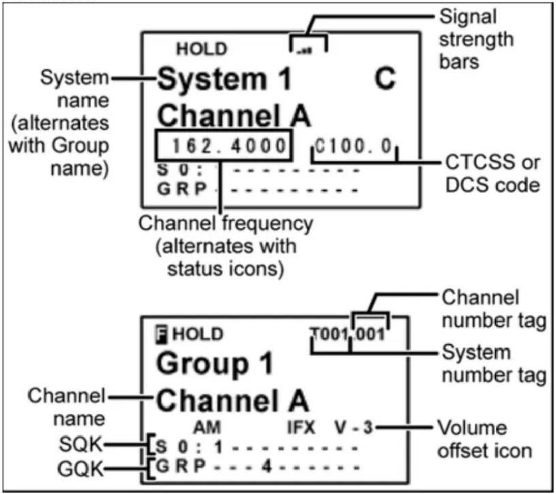
- To see the alternate information on the display at the top, cycle through the display modes.
• To see the display at the bottom of the diagram, tap FUNCTION. - For an explanation of System and Channel Number Tags, see Number Tags.
- For an explanation of the volume offset level, see Volume Offset.
Trunked system display
UBCD396XT
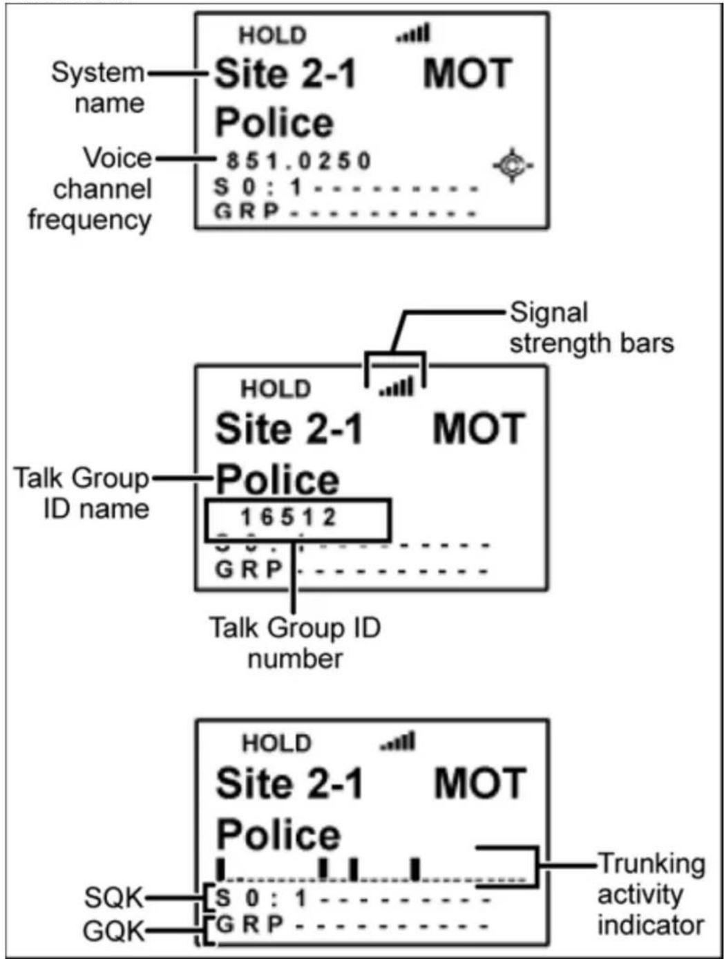
Service search with scan hold display
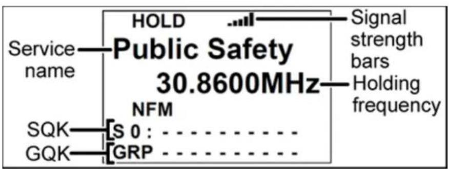
flowchart
graph TD
    A["Service name"] --> B["HOLD"]
    B --> C["Public Safety 30.8600MHz"]
    C --> D["NFM"]
    D --> E["SQK"]
    D --> F["GQK"]
    C --> G["GRP"]
    H["Signal strength bars"] --> I["Holding frequency"]
39. Edit Talk Group ID
All Talk Group IDs must be in the proper format for each system type.
Motorola Type I Systems
Enter the Talk Group ID in the following format:
BFFF-SS
• B = Block # (1 digit)
• F = Fleet # (2-3 digits)
- S = Sub-Fleet # (1-2 digits)
Press the decimal key to enter the hyphen.
(If you try to enter a hexadecimal TGID for a Type I system, the scanner treats the entry as a decimal number.)
Motorola Type II Systems
- Decimal format: Enter the TGID in numbers only, up to 5 digits
- Hexadecimal format: up to 3 characters Select the first Hex character (0 through F), then move the cursor to the right and select the second character. Press yes when you're finished.
P25 Single Frequency Systems or Standard System Trunk Site
- Decimal format: Enter the TGID in numbers only, up to 8 digits
• Hexadecimal format: up to 6 characters
Select the first Hex character (0 through F), then move the cursor to the right and select the second character. Press yes when you're finished.
EDACS Wide or Narrow Systems
AFS format
Enter the Talk Group ID in the following format:
AA-FFS
UBCD396XT
- A = Agency # (00 - 15)
• F = Fleet # (00 - 15) - S = Sub-fleet # (0 - 7)
Press the decimal key to enter the hyphen.
Leave the Fleet or Sub-Fleet # empty to treat it as a wildcard (any Sub- Fleet within that Fleet). For example, "15-" will match all TGIDs for Agency 15. "15-04-" will match all TGIDs for Agency 15, Fleet 4.
I-Call channel (Motorola, P25 or EDACS)
Enter the Talk Group ID in the following format:
i{ID number}
Press the decimal key to enter the lower-case i, then enter the ID number.
To monitor all iCalls, enter the iCall wildcard i0 in decimal or i in HEX.
LTR systems
Enter the Talk Group ID in the following format:
AHHUUU
• A = Area Code (0 or 1)
• H = Home repeater (01 - 20)
• U = User ID (000 - 254)
Press the decimal key to enter the hyphen.
Leave the User ID empty to treat it as a wildcard. For example, "1-15-" will match all User IDs for Area Code 1, Home repeater 15.
40. Edit Band Plan
(Motorola systems only) The scanner prompts you to choose one of the two standard band plan types: 800/900 Standard or 800 Splinter. Choose Custom if you need to create your own band plan.
Creating a custom band plan
You will need to create a custom band plan for a Motorola VHF, UHF, and 800 MHz system. When you select Custom, the scanner prompts you for the following information:
Band plan number
Select one of the 6 available band plan numbers, from Band Plan 1 through Band Plan 6.
Set Base Freq
- Input the lower limit of the band frequency.
- Input the upper limit of the band frequency.
(See Calculating upper base frequencies for more information.)
Set Offset
Enter the offset.
Set Spacing
Select the number of kHz between each channel. Your options are:
| 5.00 | 6.25 | 10.00 | 12.50 | 15.00 | 18.75 | 20.00 | 25.00 |
| 30.00 | 31.25 | 35.00 | 37.50 | 40.00 | 43.75 | 45.00 | 50.00 |
| 55.00 | 56.25 | 60.00 | 62.50 | 65.00 | 68.75 | 70.00 | 75.00 |
| 80.00 | 81.25 | 85.00 | 87.50 | 90.00 | 93.75 | 95.00 | 100.00 |
UBCD396XT
41. Calculating upper base frequencies
Custom Band Plans (800 Custom, VHF, UHF) require that you enter both a lower and an upper base frequency value. Here's how to determine these values.
The Lower Base Frequency (or Base) is always the base frequency as provided in the RRDB. The Upper Base Frequency is calculated from the following formulas:
For sites with a single band plan:
$$ \text { Base } + ((7 5 9 - \text { Offset }) \times \text { Step }) $$
Where:
- Base = the lower base frequency listed in RRDB.
- Offset = the offset for this entry.
- Step = the step for this entry.
For sites with multiple band plans:
$$ \text { Upper } \text { Basen } = \text { Basen } + (\text { Offset } n + 1 - 1 - \text { Offset } n) \times \text { Step } n $$
Where:
- Basen is the lower base frequency for the entry.
- Offset n + 1 is the Offset for the next band plan (for the last table, use 760)
- Offset n is the offset for this band plan
- Step n is the step for this band.
For example:
Custom Frequency Table
| Entry | Base | Spacing | Offset |
| A | 155.4150 | 15.0 | |
| B | 157.2000 | 12.5 | |
| C | 157.4700 | 15.0 |
| For entry A: | |
| Upper BaseA | = BaseA + (OffsetB-1 - OffsetA) × StepA |
| Upper BaseA | = 155.415 MHz + (436 - 1 - 380) × 15 kHz |
| Upper BaseA | = 155.415 MHz + 55 × 0.015 MHz |
| Upper BaseA | = 155.415 MHz + 0.825 MHz |
| Upper BaseA | = 156.240 MHz |
| For entry B: | |
| Upper BaseB | = BaseB + (OffsetC - 1 - OffsetB) × StepB |
| Upper BaseB | = 157.200 MHz + (454 - 1 - 436) × 12.5 kHz |
| Upper BaseB | = 157.200 MHz + 17 × 0.0125 MHz |
| Upper BaseB | = 157.200 MHz + 0.2125 MHz |
| Upper BaseB | = 157.4125 MHz |
| For entryC: | |
| Upper Basec | = Basec + (OffsetC+1 - 1 - OffsetC) × Stepc |
| Upper Basec | = 157.470 MHz + (760 -1 - 454) × 15 kHz |
| Upper Basec | = 157.470 MHz + 305 × 0.015 MHz |
| Upper Basec | = 157.470 MHz + 4.575 MHz |
| Upper Basec | = 162.045 MHz |
UBCD396XT
42. CloseCall
The Close Call (CC) feature searches for signals that are stronger than other signals on the band (indicating the transmitter is probably somewhere close by). This menu lets you change the operation settings of the close call feature; you can change the overall close call options through the Srch/CloCall Opt menu.
Close Call Only
Search the selected bands for close call hits; the scanner stops all other scanning for a close call only search.
CC Auto Store
Start a close call search. When a close call hit is detected, the scanner stores that frequency in the system named Close Call in the Found Channels group. The scanner saves found channels until it reaches the number set in the Max Auto Store setting on the Srch/CloCall Opt menu.
Hits with Scan
The scanner stores the 10 most recent close call hits to a temporary system; you can set the options for this temporary system, just like you can for permanent systems. The scanner deletes the 10 saved frequencies in this temporary system when you turn the power off. If you want to save the any of these frequencies permanently, you need to store them to a programmed system or use the CC Auto Store feature.
Set Quick Key
Assign this close call hits system to a Quick Key so you can easily enable or disable it during scanning. Enter a number from 0 to 99; tap NO (the decimal point) if you don't want to assign this system or site to a Quick Key. (For more information, see Quick Keys.)
Set Number Tag
Assign a number to this system you can use to tune directly to the system. Choose a number from 0 to 999. (For more information, see Number Tags.) Note that you can only set a system number tag for the Close Call system.
UBCD396XT
Set Lockout
Decide whether you want to lock out the system so the scanner will ignore it during Scan and Search modes. If you lock out the system none of the found channels will be scanned conventionally.
Unlocked: The system is not locked out.
Temporary L/O: The system is locked out until you turn the scanner off and back on.
Lockout: The system is permanently locked out.
Set Hold Time
Set the minimum number of seconds the scanner should spend checking this close call hits system even if there is no traffic on any channel. (The scanner always checks each channel in a close call hits system once even if the hold time is set to 0 seconds.) Select the number of seconds from 0 through 255 (0 is the default).
Set CC Mode
Choose whether scanner runs close call checks in the background, while you're performing other scans or searches. (The scanner never runs close call checks when you're in tone-out mode.)
- Off: The scanner does not run close call checks in the background.
- CC DND : The scanner runs close call checks every 2 seconds, but it will not leave an active channel for a close call check.
- CC Pri : The scanner runs close call checks every 2 seconds, even if the current channel is active. The scanner runs the close call check even while you are monitoring a transmission.
Set CC Override
Choose On if you want the scanner to stop its current operation and automatically jump to the frequency when it detects a close call hit. Choose Off if you want the scanner to alert you to the close call hit and prompt you to change frequency; if you choose not to change frequency, the scanner times out and returns to its previous operation.
Set CC Alert
UBCD396XT
Decide whether the scanner triggers an alert tone and light when it detects a close call hit. (Compare this to the system setting Emergency Alert, which triggers a tone and light when a Talk Group contains an emergency flag.) The available options for Set Alert Tone and Set Alert Light are common to both types of alerts.
Set Alert Tone
Set Alert Light
Set CC Pause
Choose how long you want the scanner to pause on a close call hit before going back to its previous operation; this setting only applies when the Set CC Override feature is turned off. Choose a pause time of 3, 5, 10, 15, 30, 45, or 60 seconds. If you want the scanner to wait for your input whenever it detects a close call hit, select Infinite.
Set CC Bands
Choose whether you want the scanner to search for close call hits on the frequency bands listed below. Select each band you want to search, then press YES to turn that band On.
The scanner only searches for close call hits on bands that are turned on.
| Band | Frequencies |
| VHF Low 1 | 25.0000–53.9900 MHz |
| VHF Low 2 | 54.0000–107.9000 MHz |
| Air Band | 108.0000–136.9875 MHz |
| VHF High 1 | 137.0000–224.9000 MHz |
| VHF High 2 | 225.0000–319.9750 MHz |
| UHF | 320.0000–520.0000 MHz |
UBCD396XT
| 800 MHz+ | 758.0000–960.0000 MHz1240.0000–1300.0000 MHz |
UBCD396XT
43. Priority Scan
This section applies to conventional system priority mode only. For priority on trunked systems, turn on the Priority ID system option and set the desired channels as priority channels.
Priority mode has two "sub modes" (similar to Close Call and Close Call Only):
- In Priority Scan mode, the scanner pauses the current operation at a designated interval to check for activity on any unlocked channels set as priority channels.
After the priority channel check is complete, the scanner resumes the previous operation.
- In Priority Plus Scan mode, the scanner stops the current operation and only checks the priority channels.
Priority Scan menu
Use the Priority Scan menu to control how Priority mode operates:
Set Priority
Choose one of the following priority scan methods:
- On : Enter Priority Scan mode; also, the scanner performs a normal priority scan whenever you enter Priority mode in the future.
- Plus On : Enter Priority Plus Scan mode; also, the scanner performs a priority plus scan whenever you enter Priority mode in the future.
- Off: Exit Priority mode, and do not go into Priority mode in the future.
Set Interval
Decide how many seconds you want the scanner to wait between priority channel checks. Enter a number between 1 and 10 seconds. (This setting is used in normal priority scans only.)
UBCD396XT
MaxCHs/Pri-Scan
Decide how many priority channels the scanner checks during each interval. Enter a number between 1 and 100. If the number of priority channels is greater than the number you enter here, the scanner divides them into groups. For example, if you set the maximum channels to 20 and there are 100 priority channels, the scanner checks those 100 channels in groups of 20 and takes a total of 5 intervals to complete the priority scan.
UBCD396XT
44. Program Location
The Program Location menu lets you create and edit points of interest (POI), intersections( Dangerous Xing ), and roads ( Dangerous Road ). The available settings vary for each location type.
POI
Edit Name
Enter a name or edit the existing one. Names can be 16 characters long, and they can contain upper and lower case letters, punctuation, and spaces. Turn the SELECT VOLUME-SQUELCH knob on the handheld scanners or the SCROLL/FUNCTION knob on mobile scanners to choose the character you want, then press 6 (right cursor) to move the cursor to the next character.
Set Type
When you create a location, the location is created as the type you are currently viewing (POI, Dangerous Xing, or Dangerous Road). If you want to change the location type, you can select the new location type here.
When you change the location type, the scanner goes back to the Program Location menu. Select the new location type to edit this location; the scanner resets the available options based on the new location type.
Set Alert
This menu lets you configure whether the scanner triggers an alert tone and light when you approach this location.
Set Alert Light
This setting is exactly the same as its counterpart on the system, site, and channel menus.
Set Alert Tone
Choose one of the available alert tones for this POI:
- Alert 1 :
1047 Hz for 125 ms / Silence for 50 ms / 1047 Hz for 125 ms / Silence for
UBCD396XT
50 ms / 1319 Hz for 125 ms / Silence for 50 ms / 1568 Hz for 125 ms / Silence for 175 ms / 1319 Hz for 125 ms / Silence for 50 ms / 1568 Hz for 125 ms
- Alert 2 :
1047 Hz for 200 ms / Silence for 200 ms / 1760 Hz for 250 ms / Silence for 100 ms / 1397 Hz for 250 ms
- Alert 3 :
2093 Hz for 125 ms / Silence for 50 ms / 1976 Hz for 125 ms / Silence for 50 ms / 2093 Hz for 125 ms
- Alert 4 :
1319 Hz for 25 ms / Silence for 50 ms / 1397 Hz for 25 ms / Silence for 50ms / 1175 Hz for 25 ms / Silence for 50 ms / 1319 Hz for 25 ms
- Off (No alert tone sounded).
If you select an alert tone, the scanner prompts you to select the volume level (Level 1 through Level 15) you want to the alert tone to use; leave the volume at Auto to have the scanner sound the alert tone without changing the volume.
Set Location Info
Enter how far out from this location you want the scanner to alert you. You can configure the scanner to sound an alert tone and flash a light when you reach the radius entered here. The scanner treats the number you enter here as miles or kilometres depending on the value you selected in the Set Unit field in the Set GPS Format menu (under the main Settings menu). Enter a range from 0.05 through 4.0 mi/km, in 0.05 mi/ km steps.
Set Lockout
Decide whether you want to lock out this location so the scanner no longer checks it.
UBCD396XT
Choose Unlocked (default), Temporary L/O (the location is locked out until you turn the scanner off and back on), or Lockout (the location is locked out until you change this setting).
Delete Location
Delete this location and its settings, including any alert settings.
New Location
Create a new location.
Dangerous Xing and Dangerous Road menus
(The settings and available options for dangerous crossings and dangerous roads are exactly the same.)
Edit Name
Enter a name or edit the existing one. Names can be 16 characters long, and they can contain upper and lower case letters, punctuation, and spaces. Turn the SELECTVOLUME- SQUELCH knob on the handheld scanners to choose the character you want, then press 6 (right cursor) to move the cursor to the next character.
Set Type
When you create a location, the location is created as the type you are currently viewing (POI, Dangerous Xing, or Dangerous Road). If you want to change the location type, you can select the new location type here. When you change the location type, the scanner goes back to the Program Location menu. Select the new location type to edit this location; the scanner resets the available options based on the new location type.
Set Alert Volume
Activate the alert tone for this location. Select the volume level (Level 1 through Level 15) you want to the alert tone to use, or select Auto to have the scanner sound the alert tone without changing the volume. If you don't want the scanner to sound an alert as you approach this location, select Off.
The tone pattern varies depending on what type of location this is:
UBCD396XT
– Dangerous Xing alert tone:
1175 Hz for 250 ms / Silence for 50 ms / 1319 Hz for 50 ms / Silence for 50 ms / 1397 Hz for 250 ms
– Dangerous Road alert tone
1568 Hz for 250 ms / Silence for 50 ms / 1760 Hz for 50 ms / Silence for 50 ms / 1976 Hz for 250 ms / Silence for 50 ms / 2093 Hz for 50 ms / Silence for 50 ms / 1047 Hz for 250 ms
Set Alert Light
This setting is exactly the same as its counterpart on the system, site, and channel menus.
Set Location Info
Decide whether the scanner alerts you of this Dangerous Xing or Road each time you approach it or only when you are traveling in a particular direction. To make the alert direction-dependent, select the direction from the list; select All Range to be alerted regardless or your direction.
Set Speed Limit
Decide whether the scanner alerts you of this Dangerous Xing or Road each time you approach it or only when you are traveling above a certain speed. To make the alert speed-dependent, enter the speed limit for this location; leave the speed limit blank to be alerted regardless of your speed. The scanner treats the number you enter here as miles or kilometers depending on the value you selected in the Set Unit field in the Set GPS Format menu (under the main Settings menu). Enter a range from 0 through 200 mi/km, in 1 mi/km steps.
Set Lockout
Decide whether you want to lock out this location so the scanner no longer checks it.
UBCD396XT
Choose Unlocked (default), Temporary L/O (the location is locked out until you turn the scanner off and back on), or Lockout (the location is locked out until you change this setting).
Delete Location
Delete this location and its settings, including any alert settings.
New Location
Create a new location.
UBCD396XT
45. Search and Store
With this feature, the scanner searches a system and saves any frequencies it finds activity on. When the scanner detects activity on a frequency, it verifies that the frequency has not already been stored, then adds the frequency to the Found Channels group. (Since these frequencies are stored with individual systems, you must have at least one programmed system to use the Search and Store feature.)
The scanner displays a list of all programmed systems. Select the system you want to search and add found channels to. The options you have depend on the type of system you select:
- If the system you selected is a conventional system, the scanner prompts you to select a custom search or a preset service search range.
- If the system you selected is a trunked system, the scanner prompts you to select a site within that system. The scanner searches the site for active Talk Groups and stores the Talk Group ID to the Found Channels group. (If the site you selected is locked, the scanner automatically unlocks it and begins the search.)
- If the system you selected is an EDACS SCAT system, the scanner displays an error message: the search and store feature can't be used on EDACS SCAT systems.
UBCD396XT
46. Search for...
Use this menu to start a search, to change the options for the three different types of searches, and program the 3 search keys.
Service Search
Start a search of one of the 8 preset service bands. Choose from Air, CB Radio, UHF CB Radio, Racing, FM Broadcast, Police, Marine, Railroad.
Edit Service
This menu lets you change the default settings for the 12 preset service bands. Select the service you want to edit from the list, then set the following options:
Set Delay Time
Set the number of seconds the scanner should wait after a transmission stops before moving on to the next channel. Select 0, 1, 2 (default), 5, 10, or 30 seconds. To have scanner leave the channel after a designated number of seconds whether the transmission stops or not, select one of the negative values. Choose -10 seconds to have the scanner leave the channel after 10 seconds even if the transmission is still going on; choose -5 seconds or -2 seconds to have the scanner leave after 5 seconds or 2 seconds, respectively.
Set Attenuator
Turn on attenuation to reduce the signal strength by 20 dB. All frequencies in the search range are attenuated during search.
Set Audio AGC
Turn on Automatic Gain Control (AGC) for this system. When you activate this feature, the scanner automatically adjusts the volume for each channel based on the signal strength. You can turn on the gain control for Analog and Digital signals separately.
To change the settings for the audio AGC, see Adjust Audio AGC
P25 Waiting Time
UBCD396XT
When searching in a band that has a mix of analog and digital signals (i.e., where the Audio Mode is set to All), it is possible to have false decode problems that results in digital noise at the beginning of transmissions. To prevent this, a user-configurable P25 wait time (from 0 to 1000 ms) has been added.
During the wait time, the scanner evaluates the received signal; if it detects P25 data, the scanner opens squelch immediately. If it does not detect any P25 data, the scanner opens squelch as soon as the wait time expires.
Note: Any analog transmissions on this channel will lose the first part of the transmission, up to the wait time you set here.
Select the number of milliseconds (after the start of a transmission) the scanner should wait while checking for P25 data. Choose a number from 0 through 1000 ms in 100 ms increments. The scanner only applies the wait time when Tone/Code Search in Srch/CloCall Opt is set to Off.
Search with Scan
Custom Search
Start a search of the 10 custom search ranges.
Edit Custom
This menu lets you program the ten custom search ranges. Select the custom search you want to edit from the list, then set the following options:
Edit Name
Enter a name or edit the existing one. Names can be 16 characters long, and they can contain upper and lower case letters, punctuation, and spaces. Turn the SELECTVOLUME- SQUELCH knob on the handheld scanners or the SCROLL / FUNCTION knob on mobile scanners to choose the character you want, then press 6 (right cursor) to move the cursor to the next character.
Edit Srch Limit
Change the range of frequencies covered by this custom search. The scanner prompts you to input the lower frequency limit and then the upper frequency limit.
UBCD396XT
Set Delay Time
Set the number of seconds the scanner should wait after a transmission stops before moving on to the next channel. Select 0, 1, 2 (default), 5, 10, or 30 seconds.
To have scanner leave the channel after a designated number of seconds whether the transmission stops or not, select one of the negative values. Choose -10 seconds to have the scanner leave the channel after 10 seconds even if the transmission is still going on; choose -5 seconds or -2 seconds to have the scanner leave after 5 seconds or 2 seconds, respectively.
Set Modulation
Select what type of modulation the scanner should use for this frequency or channel. (Only the modulation types available for this frequency or channel are displayed.)
| Auto | The scanner uses the default modulation type for this frequency's band. |
| AM | The scanner treats the frequency as an AM band. |
| NFM | The scanner treats the frequency as a Narrowband FM band. |
| FM | The scanner treats the frequency as an FM band. |
| WFM | The scanner treats the frequency as a Wideband FM band. |
| FMB | The scanner treats the frequency as an FM broadcast band. |
Set Attenuator
Turn on attenuation to reduce the signal strength by 20 dB. All frequencies in the search range are attenuated during search.
Set Step
Select the number of kHz between each channel. Choose 5.0, 6.25, 7.5, 8.33, 10.0, 12.5, 15.0, 20.0, 25.0, 50.0 or 100.0 kHz . Select Auto to use the default step for this band.
Set C-Ch Only
If you set C-Ch Only Mode to On, the scanner will only search for control channel data. If it detects such data it will stop on the control channel and display channel activity for the found system. For Motorola systems, it will try to follow voice channel traffic using the Motorola Band Plan you select in the next setting. It will
UBCD396XT
also display the name of the found system if the system's ID matches a known system.
Set MOT Band Plan
If this custom search is a Motorola system, you need to select a band plan, just like you do when you program a Motorola system for scanning. See Edit Band Plan for more information.
Set Audio AGC
Turn on Automatic Gain Control (AGC) for this system. When you activate this feature, the scanner automatically adjusts the volume for each channel based on the signal strength. You can turn on the gain control for Analog and Digital signals separately.
To change the settings for the audio AGC, see Adjust Audio AGC
P25 Waiting Time
When searching in a band that has a mix of analog and digital signals (i.e., where the Audio Mode is set to All), it is possible to have false decode problems that results in digital noise at the beginning of transmissions. To prevent this, a user-configurable P25 wait time (from 0 to 1000 ms) has been added.
During the wait time, the scanner evaluates the received signal; if it detects P25 data, the scanner opens squelch immediately. If it does not detect any P25 data, the scanner opens squelch as soon as the wait time expires.
Note: Any analog transmissions on this channel will lose the first part of the transmission, up to the wait time you set here.
Select the number of milliseconds (after the start of a transmission) the scanner should wait while checking for P25 data. Choose a number from 0 through 1000 ms in 100 ms increments. The scanner only applies the wait time when Tone/Code Search in Srch/CloCall Opt is set to Off.
Search with Scan
Search and Store
Search a stored system and save the frequency information of any active channels.
UBCD396XT
Set Search Key
The scanner has three one-touch search keys (number keys 1, 2, and 3) that you can assign to any saved search range.
- Select the search key you want to program (Search Key 1 through Search Key 3).
- Select the search range you want to assign to this key. The search range can be a service search, a custom search, a tone-out search, or a band scope search.
- Press YES to confirm the selection.
Once you assign a search range to a key, you can start the search just by pressing the appropriate key.
UBCD396XT
47. Search with Scan
Set Quick Key
Assign this search range to a Quick Key so you can easily enable or disable it during scanning. Enter a number from 0 to 99; tap NO (the decimal point) if you don't want to assign this search range to a Quick Key. (For more information, see Quick Keys.)
Set Startup Key
Assign this search range to a Startup Key so you can lock or unlock it during power up. Enter a number from 0 to 9; tap NO (the decimal point) if you don't want to assign this search range to a Startup Key. (For more information, see Startup Keys.)
Set Number Tag
Assign a number to this search range that you can use to quickly access the first frequency of the search range. Choose a number from 0 to 999. (For more information, see Number Tags.)
Set Lockout
Decide whether you want to lock out the search so the scanner will ignore it during Scan and Search modes. Choose one of the following options:
- Unlocked: The search range is included while scanning.
- Temporary L / O : The search range is locked out until you turn the scanner off and back on.
- Lockout: The search range is permanently locked out.
Set Hold Time
Set how long the scanner spends checking this search range before moving to the next search range or system. (2 seconds is the default).
48. Set Alert Tone
Choose one of the 9 different tone patterns for the scanner to use for the alert tone:
| Alert 1 | 4000 Hz for 50 ms » Silence for 20 ms » 4000 Hz for 50 ms » Silence for 20 ms » 4000 Hz for 50 ms |
| Alert 2 | 800 Hz for 50 ms » Silence for 20 ms » 1050 Hz for 50 ms » Silence for 20 ms » (repeat twice) |
| Alert 3 | 800 Hz for 50 ms » Silence for 20 ms » 1050 Hz for 50 ms » Silence for 20 ms » 4000 Hz for 100 ms |
| Alert 4 | 120 Hz for 10 ms » 800 Hz for 10 ms » 1200 Hz for 10 ms (repeat 5 times) |
| Alert 5 | 1200 Hz for 150 ms |
| Alert 6 | 1200 Hz for 70 ms » Silence for 50 ms » 1200 Hz for 70 ms |
| Alert 7 | 2000 Hz for 200 ms » Silence for 10 ms » 800 Hz for 150 ms (repeat 3 times) |
| Alert 8 | 500 Hz for 40 ms » Silence for 10 ms » 500 Hz for 40 ms » Silence for 10 ms » 500 Hz for 40 ms |
| Alert 9 | 2400 Hz for 70 ms » Silence for 20 ms » 3000 Hz for 70 ms » Silence for 70ms (repeat twice) |
| Off | No alert tone sounded. |
If you select an alert tone, the scanner prompts you to select the volume level (Level 1 through Level 15) you want to the alert tone to use; leave the volume at Auto to have the scanner sound the alert tone without changing the volume.
This menu lets you set general options for how the scanner operates in Search and Close Call modes.
Freq Lockouts
- Rvw Search L/O : This option displays a list of all locked out frequencies.
To unlock any frequency on the list, just select it and press YES. - Unlock All: This option removes the locks on all frequencies at once.
Broadcast Screen
Choose whether you want the scanner to screen out common broadcast bands and ignore hits on these bands. You can screen out signals on 4 preset bands and up to 10 custom bands. The preset bands are:
- Pager (148.0000 - 149.2500 MHz)
- FM (88.0000 - 108.0000 MHz)
- UHF TV (764.0000 - 775.9999 MHz)
- VHF TV (50.0000 - 70.0000 MHz)
$$ (7 9 4. 0 0 0 0 - 8 1 9. 9 9 9 9 \mathrm{MHz}) $$
$$ (1 7 4. 0 0 0 0 - 2 2 5. 0 0 0 0 \mathrm{MHz}) $$
Your options for broadcast screening are listed below:
Set All Band On
Turn on screening for all broadcast bands and ignore any hits on these frequencies.
Set All Band Off
Turn off screening for all broadcast bands, and treat hits on these frequencies the same as any other band.
Set Each Band
Turn screening on or off for each band individually. The scanner displays the bands listed above. Select the band you want to change, then press YES to toggle the setting.
Program Band
Create up to 10 custom bands that you want the scanner to screen out hits on.
-
Select a custom band slot (Band 1 through Band 10).
-
When the scanner prompts you, input the lower frequency limit.
-
When the scanner prompts you, input the upper frequency limit.
-
Once you create the custom band, turn screening on or off the same way you did for the preset bands.
Tone/Code Search
Choose whether the scanner searches an active frequency for CTCSS/DCS tones (CTCSS/DCS Search), P25 NAC codes (P25 NAC Search), or neither (Off). (The scanner ignores this setting in AM, WFM, and FMB bands.)
Repeater Find
If you turn this feature on, whenever the scanner detects a signal on a common repeater input frequency, it automatically searches for that signal on the output frequency. If it finds the signal on the output frequency, the scanner displays Repeater Found and switches to monitor the output frequency.
Max Auto Store
Enter the maximum number of hits you want the scanner to store during Search and Store mode or Close Call Auto Store mode. When the number of stored hits reaches the number you enter here, the scanner stops storing hits. Enter a number from 1 to 256.
Set Delay Time
This setting is used to set the delay time for Quick Search, Close Call, and the CC Hits system.
Set the number of seconds the scanner should wait after a transmission stops before moving on to the next channel. Select 0, 1, 2 (default), 5, 10, or 30 seconds.
To have scanner leave the channel after a designated number of seconds whether the transmission stops or not, select one of the negative values. Choose -10 seconds to have the scanner leave the channel after 10 seconds even if the
UBCD396XT
transmission is still going on; choose -5 seconds or -2 seconds to have the scanner leave after 5 seconds or 2 seconds, respectively.
Set Attenuator
Turn on attenuation to reduce the signal strength by 20 dB. When you turn on this setting, all frequencies in Quick Search mode, Close Call mode, and the Band Scope will be attenuated.
Set Audio AGC
Turn on Automatic Gain Control (AGC) for this system. When you activate this feature, the scanner automatically adjusts the volume for each channel based on the signal strength. You can turn on the gain control for Analog and Digital signals separately.
To change the settings for the audio AGC, see Adjust Audio AGC
P25 Waiting Time
During search and Close Call operation, it is possible to have false decode problems that result in digital noise at the beginning of transmissions. To prevent this, a userconfigurable P25 wait time (from 0 to 1000 ms) has been added. During the wait time, the scanner evaluates the received signal; if it detects P25 data, the scanner opens squelch immediately. If it does not detect any P25 data, the scanner opens squelch as soon as the wait time expires.
Note: Any analog transmissions will lose the first part of the transmission, up to the wait time you set here.
Select the number of milliseconds (after the start of a transmission) the scanner should wait while checking for P25 data. Choose a number from 0 through 1000 ms in 100 ms increments. This setting will be applied in Close Call, Quick Search, and Band Scope modes.
50. StartupKeys
Startup Keys let you change the lockout state for several systems, sites, and search ranges all at the same time. When you activate the Startup Key, the scanner checks all systems, sites, or search ranges and locks or unlocks them according to these rules:
- If any systems, sites, or search ranges do not have a Startup Key assigned, the scanner does not change their locked/unlocked state (i.e., if they are unlocked, it leaves them unlocked).
- If any systems, sites, or search ranges do have an assigned Startup Key, the scanner compared the assigned Startup Key to the one you activated:
○ If a system's Startup Key does not match the one you activated, the scanner locks that system.
○ If a system's Startup Key matches the one you activated, the scanner unlocks that system and enables all of its Quick Keys.
Assigning Startup Keys
- Multiple systems, sites, and search ranges can share the same Startup Key.
- Startup Keys range from 0 to 9.
- If you do not want a system, site, or search range to be affected by any Startup Keys, enter the decimal point for the Startup Key (this is the default setting).
To a conventional system:
- Open the Program System menu.
- Select the system you want to assign the Startup Key to.
- Select Edit Sys Option, then select Set Startup Key.
- Enter the Startup Key you want to use for this system.
To a trunked system:
- Open the Program System menu.
- Select the system you want to assign the Startup Key to.
- Select Edit Site, then select the site you want.
- Select Set Startup Key, then enter the Startup Key you want to use for this site.
To a service search range :
- Open the Search for... menu.
UBCD396XT
-
Select Edit Service, then select the service search range you want to assign the Startup Key to.
-
Select Search with Scan, then select Set Startup Key.
-
Enter the Startup Key you want to use for this search range.
To a custom search range :
-
Open the Search for... menu.
-
Select Edit Custom, then select the custom search range you want to assign the Startup Key to.
-
Select Search with Scan, then select Set Startup Key.
-
Enter the Startup Key you want to use for this custom search range.
Using Startup Keys
To activate a Startup Key:
-
Turn the scanner off.
-
Press & hold the number key that corresponds to the Startup Key while you power the scanner on. (e.g. To activate Startup Key configuration # 2, press & hold 2 on the number pad while turning the scanner on.)
-
Continue holding the number key until the scanner display shows the number of the Startup Key configuration (In the example above, the display shows Startup Config. Key No. 2).
For example, say you have 4 systems programmed according to the table below:
| Assigned Startup Key | State |
| 3 Locked | |
| None (.) Unlocked | |
| None (.) Locked | |
| 9 Unlocked |
Here is the result if you power on the scanner while you press and hold 3 :
| Assigned Startup Key | Previous state | Resulting state |
| 3 Locked Unlocked | ||
| None (.) Unlocked Unlocked (no change) | ||
UBCD396XT
| None (.) Locked | Locked (no change) | |
| 9 Unlocked | Locked |
Here is the result if you power on the scanner while you press and hold 5 :
| Assigned Startup Key | Previous state | Resulting state |
| 3 Locked Locked | ||
| None (.) Unlocked Unlocked (no change) | ||
| None (.) Locked Locked (no change) | ||
| 9 Unlocked Locked | ||
51. Tone A and Tone B Settings
You can configure the scanner to search for tones in several different ways, based on the values you enter for Tone A and Tone B:
| Tone setting | Positive Number | Tone B Setting | Positive number | |
| Operation | Monitor the channel for two-tone pages only. The scanner opens squelch and displays the tone information when the following occur:1. The scanner detects a tone that matches the value you set for Tone A.2. The tone is at least 250 ms long.3. Within 500 ms, the scanner detects a second tone that matches the value set for Tone B.4. The second tone is at least 100 ms long. | |||
| Tone setting | Positive Number | Tone B Setting | 0.0 Hz | |
| Operation | Monitor the channel for single-tone pages only. The scanner opens squelch and displays the tone information when the following occur:1. The scanner detects a tone that matches the value you set for Tone A.2. The tone is at least 1.25 seconds long and not more than 3.75 seconds long. | |||
| Tone setting | 0.0 Hz | Tone B Setting | Positive number | |
| Operation | Monitor the channel for group tones only. The scanner opens squelch and displays the tone information when the following occur:1. The scanner detects a tone that matches the value you set for Tone B.2. The tone is at least 3.75 seconds long. | |||
| Tone setting | 0.0 Hz | Tone B Setting | 0.0 Hz | |
| Operation | Monitor the channel for two-tone pages, single-tone pages, and group tones. This tone out search mode works as follows:1. All detected tones are compared to the three criteria listed above. | |||
UBCD396XT
| 2. If the tone meets any one of the criteria, the scanner checks to see if this tone frequency is already saved to a tone out channel with the same frequency, modulation, and attenuator settings.3. If the detected tone matches a saved tone, the scanner opens squelch.4. If the detected tone does not match any saved tones, the scanner opens squelch, flashes the tone information on the display, and asks if you want to save the tone information. |
UBCD396XT
52. Tone-Outfor...
Tone-Out Standby
Check the tone out channels for paging tones, according to each channel's individual settings.
Tone-Out Setup
This menu lets you configure the 10 tone-out channels. Select the channel you want to edit from the list, then set the frequency, tone, and other options for that channel.
Edit Name
Enter a name or edit the existing one. Names can be 16 characters long, and they can contain upper and lower case letters, punctuation, and spaces. Turn the SELECTVOLUME-SQUELCH knob on the handheld scanners to choose the character you want, then press 6 (right cursor) to move the cursor to the next character.
Set Frequencies
Use this menu to program frequencies for this Tone Out channel.
Set Tone
This menu lets you configure the type of tone out search. Select the tone you want to edit (Edit Tone A or Edit Tone B), then set the frequency for that tone. Enter a frequency between 250 Hz and 3500 Hz, or set the frequency to 0 Hz. (See Tone A and Tone B Settings for more information.)
Set Delay Time
Set the number of seconds the scanner should wait after a transmission stops before moving on to the next channel. Select 0, 1, 2 (default), 5, 10, or 30 seconds. To have the scanner wait for your input before moving on to the next channel, select Infinite.
Set Alert
UBCD396XT
Decide whether the scanner triggers an alert tone and light when it detects a tone on this channel. (Compare this to the system setting Emergency Alert, which triggers a tone and light when a Talk Group contains an emergency flag.) The available options for Set Alert Tone and Set Alert Light are common to both types of alerts.
Set Alert Tone
Set Alert Light
Set Audio AGC
Turn on Automatic Gain Control (AGC) for this Tone-Out channel. When you activate this feature, the scanner automatically adjusts the volume for the channel based on the signal strength.
To change the settings for the audio AGC, see Adjust Audio AGC.
Tone-Out Search
You can set the scanner to search for and identify the tones used in tone-outs. To do so, you set both the A and B tones to a value of "0". See Tone A and Tone B Settings for more information.
53.Key Safe Mode
Key Safe mode locks out the programming menu and more advanced functions so the user can't accidentally "break" the scanner. This mode is ideal for any situation where you want another person to be able to use the scanner without changing any of the settings.
To turn Key Safe mode on (or off)
- Turn the scanner off.
- Press and hold FUNCTION while you turn the scanner back on.
- The scanner display shows Key Safe Mode On (or Key Safe Mode Off), then returns to the operation it was performing when you turned it off.
- While Key Safe mode is on, MENU is disabled along with the key combinations described in the table below.
- When you try to use a disabled key combination, the scanner display shows Key Safe Mode. Press FUNC while Power On for Full Operation.
The table below shows which key combinations are disabled and which ones operate normally (depending on the operating mode the scanner is in):
| Key Name(2ndoperation)Action on: |  Hold (Close call) Hold (Close call) |  1 (Search 1) 1 (Search 1) |  2 (Search 2) 2 (Search 2) |  3 (Search 3) 3 (Search 3) |
| Tap | Normal operation | |||
| Press & hold | Normal operation | |||
| FUNCTION+ Tap | Normal operation | While Scanning: Normal operationWhile Holding: Disabled | ||
| FUNCTION+ Press & hold | Disabled | |||
| Key Name(2ndoperation)Action on: | Scan srchScan (Search) | <4 ifx4 (IF exchange) | 5 lvl5 (Volume offset) | 6> disp6 (Display mode) |
| Tap In Close Call, Tone-Out, GPS, and Band Scope | Normal operation. | |||
UBCD396XT
| modes, this key is disabled. In Search mode, this operates as the Resume function. | ||||
| FUNCTION+ Tap | Disabled While Scanning: Normal operationWhile Holding: Disabled | |||
| Key Name (2ndoperation)Action on: |  Lockout Lockout |  7(Attenuation) 7(Attenuation) |  8 (Reverse freq.) 8 (Reverse freq.) |  9(Modulation) 9(Modulation) |
| Tap | Normal operation(Temporary Lockout Only). | Normal operation. | ||
| Double tap | NA Normal operation. | |||
| Press & hold | Disabled Normal operation | |||
| FUNCTION+ Tap | NormalOperation(Temporary Lockout Only). | While scanning: Normal operationWhile Holding: Disabled | ||
| FUNCTION+ Double tap | NA | While scanning:NormaloperationWhile Holding:Disabled | Disabled | While scanning:NormaloperationWhile Holding:Disabled |
| FUNCTION+ Press & hold | Disabled | While scanning:NormaloperationWhile Holding:Disabled | Normaloperation. | While scanning:NormaloperationWhile Holding:Disabled |
| Key Name (2ndoperation)Action on: |  Backlight(Power, Lock) Backlight(Power, Lock) |  No (Decimal,Priority) No (Decimal,Priority) |  0 0 |  Yes (Enter,GPS) Yes (Enter,GPS) |
UBCD396XT
| Tap | Normal operation | operation | |
| Press & hold | Normal operation Disabled | ||
| FUNCTION+ Tap | Normal operation While | Scanning:NormaloperationWhile HoldingDisabled | Disabled |
| FUNCTION+ Press & hold | Normal operation Disabled | ||
Set Backlight
This menu lets you configure the display and key backlight.
Set Mode
Choose how you want the backlight to operate:
| 10 sec | The scanner keeps the backlight on for 10 seconds after the last operation. |
| 30 sec | The scanner keeps the backlight on for 30 seconds after the last operation. |
| Squelch | The scanner turns on the backlight when a signal breaks squelch. |
| Keypress | The scanner turns on the backlight when you press a key. |
| Infinite | The scanner leaves the backlight on all the time. |
Set Dimmer
Select the brightness of the backlight. Your options are high (brightest), middle, and low (dimmest).
Set Color
Select the color of the backlight. Your options are blue, red, magenta, green, cyan, yellow, and white.
Adjust Key Beep
Select the volume level (Level 1 through Level 15) you want the keybeep to use, or select Auto to have the scanner sound the keybeep without changing the volume. If you don't want the scanner to beep when you press the keys, select Off.
Battery Option
This menu lets you configure the advanced battery control features:
Set Battery Save
Turn the battery save feature on or off.
Enter the amount of time you want the battery to draw power while charging.
Adjust Audio AGC
Configure how the scanner handles the Automatic Gain Control (AGC) for Analog and Digital signals:
| Parameter | Definition | Analog settings | Digital settings |
| Response Time | How frequently the AGC factor updates. Decrease this value to make AGC respond faster (but this could result in pumping). Increase this value to make AGC respond more slowly. | -4 to +6 (default=0) | -8 to +8 (default=0) |
| Reference Gain | The reference level that AGC attempts to adjust the volume to. If digital and analog volumes don't match, adjust this parameter. | -5 to +5 (default=0) | -5 to +5 (default=0) |
| Gain Range | The total dynamic range of the AGC adjustments. A larger value allows a wider variation in volume. | 0 to 15 NA |
Adjust Contrast
Select one of the 15 available contrast levels for the display. As you scroll through the options, the display adjusts to the highlighted contrast level; press YES when you see the display contrast you want to use.
UBCD396XT
Set C-CH Output
Choose how you want the scanner to handle control channel data:
- Off: The scanner will not output the control channel data.
- On : The scanner will output the control channel data.
- Extend : The scanner will output the control channel data along with any description.
Set GPS Format
Configure how the scanner displays position coordinates, time, and units during GPS operation:
Set Pos Format
Select how the scanner displays longitude and latitude:
- DMS: DDD^' SS.ss : Display coordinates in degrees (DDD), minutes (MM), and seconds (SS.ss).
- DEG: DDD.dddddd : Display coordinates as decimal degrees.
Set Time Format
Select 12H for 12-hour (am/pm) time format or 24H for 24-hour time format.
Set Time Zone
Set the number of hours your local time zone differs from universal time (GMT/UTC). Select from -14 hours to +14 hours in half-hour (0.5 h) increments.
Set Unit
Select the unit used for distance: mile or kilometer (km).
Set Serial Port
Set the baud rate for the scanner's serial port. Choose from 4800, 9600, 19200, 38400, 57600, or 115200 bps; select Off to disable the serial port.
Band Defaults
Use this menu to change the default modulation and frequency step or spacing used for each band. The scanner displays the list of available bands in the following format:
{Frequency} : {modulation type} / {step}
Select the frequency band you want to edit. The scanner prompts you for the following information:
Set Modulation
Select the type of modulation you want the scanner to use as the default for this band:
AM, Narrowband FM (NFM), FM, Wideband FM (WFM), or FM broadcast (FMB).
Set Step
Select the number of kHz between each frequency or channel step: 5.0, 6.25, 7.5, 8.33, 10.0, 12.5, 15.0, 20.0, 25.0, 50.0, or 100.0 khz.
P25 LP Filter
This setting lets you set the scanner to apply a software filter that removes the 4kHz tone you can hear on some P25 systems. Note that turning on this setting increases the CPU load and could slightly degrade P25 decode performance on some systems.
Display Unit ID
The Unit ID (UID) feature lets you see the unit ID of the radio currently transmitting on Motorola, EDACS, and APCO P25 systems. To see the Unit ID, you need to first turn on the global Unit ID option in the Settings menu.
Press MENU.
Scroll to SETTINGS and press E/yes.
Scroll to Disp. Unit ID and press E/yes.
Scroll to On and press E/yes.
UBCD396XT
When turned on, in Display Modes 1 and 2 the scanner will alternate the current channel information and the Unit ID information in Line 2 of the display. In Display Mode 3, the scanner will display the Unit ID information on Line 3 of the display.
If you program a Unit ID into a channel, you can assign an Alpha to the Unit ID. You program a Unit ID just like an iCall ID (press ./no then the Unit ID).
Notes:
In some cases where you catch a transmission already in progress you will not see the Unit ID.
In some cases where a second party responds to a transmission before the channel is released, you will not see the second party's Unit ID and will continue to see the first party's Unit ID.
See Scanner Info
This menu lets you see detailed information about the memory and firmware.
% Memory Used
See the percent of overall memory used (Memory Used) along with the number of programmed Systems, Sites, and channels (CHN) and the percent of available memory positions used for each.
Firmware Version
See the firmware version (Version) and the serial number (SN) of the scanner.
55. WiredClone
This feature allows you to copy all the settings from one scanner to another of the same model:
- Use the included data transfer cables to connect the two scanners. Plug each of the cables DB9 connector into one side of a Gender Changer/Null-Modem Adaptor.
- On the scanner you want to copy from, go to the Wired Clone menu and select Master.
- On the scanner you want to copy to, go to the Wired Clone menu and select Slave.
The master scanner checks to make sure the slave is properly connected and ready to receive, then begins the data transfer. Do not disconnect the data transfer cable or turn off either scanner during the transfer.
When the transfer is finished, both scanners display a Complete message. Reboot the slave scanner to load the new settings.
All settings and data saved on the Slave scanner will be erased!
General
| Attenuation | 20dB nominal |
| Audio Output Power | 310mW nominal into 24Ω speaker |
| 20mW nominal into 32Ω stereo headphone | |
| Scan Rate | 100 channels per second max (Conventional mode) |
| Search Rate | 300 steps per second max (5kHz steps only) |
| External Jacks | Antenna Jack: SMA Type |
| Phone Jack: 3.5mm Stereo Type | |
| DC Power Jack: EIAJ TYPE-II(Center Positive) | |
| GPS/Remote Interface Jack: 4pin Mini Type | |
| Internal Speaker | 24Ω, 0.8 W Max.32mm |
| Power Requirements | 3 x AA Size Rechargeable Ni-MH Batteries (2300mAh) |
| 3 x AA size Alkaline Batteries | |
| AC Adapter (6V DC 800mA Regulated) (PS-S0680BL2) | |
| Operating Temperature | Nominal: -20°C to +60° |
| Close Call: -10°C to +60°C | |
| Size | 61.0mm(W) x 31.0mm(D) x 136.0mm(H) (Without Antenna) |
| Weight | 167g (Without Battery and Antenna) |
| Remote Functions | Direct PC control |
| Database management | |
| Wired cloning | |
| Display | 64 x 128 Full Dot Matrix LCD with multi-color back light |
| Sensitivity (nominal) 12dB SINAD | ||
| 0.3μV | 25—27.995 MHz | AM |
| 0.2μV | 28—87.9875 MHz | FM |
| 0.4μV | 88—107.9 MHz | FMB |
| 0.3μV | 108—136.9875 MHz | AM |
UBCD396XT
| 0.2μV | 137—173.9875 MHz | FM |
| 0.5μV | 174—224.9 MHz | WFM |
| 0.3μV | 225—399.975 MHz | AM |
| 0.3μV | 400—520 MHz | NFM |
| 0.3μV | 758—960 MHz | NFM |
| 0.6μV | 1240—1300 MHz | NFM |
| Signal Noise Ratio (nominal) | ||
| 50dB | 25—27.995 MHz | AM |
| 48dB | 28—87.9875 MHz | FM |
| 60dB | 88—107.9 MHz | FMB |
| 50dB | 108—136.9875 MHz | AM |
| 47dB | 137—173.9875 MHz | FM |
| 55dB | 174—224.9 MHz | WFM |
| 50dB | 225—399.975 MHz | AM |
| 40dB | 400—520 MHz | NFM |
| 41dB | 758—960 MHz | NFM |
| 37dB | 1240—1300 MHz | NFM |
| Close Call Sensitivity(nominal) | |
| 350μV | VHF Low1 Band |
| 160μV | VHF Low2 Band |
| 70μV | Air Band |
| 60μV | VHF High1 Band |
| 56μV | VHF High2 Band |
| 100μV | UHF Band |
UBCD396XT
| 200μV | 800MHz+ Band |
Frequency Range
| Frequency Range (MHz) | Modulation Step(kHz) | |
| 25.0000—27.9950 | AM | |
| 28.0000—69.9900 | FM | 10 |
| 70.0000—87.9875 | FM | 12.5 |
| 88.0000—107.9000 | FMB | 100 |
| 108.0000—136.9875 | AM | 12.5 |
| 137.0000—147.9950 | FM | 5 |
| 148.0000—173.9875 | FM | 12.5 |
| 174.0000—224.9000 | WFM | 100 |
| 225.0000—399.9750 | AM | 25 |
| 400.0000—520.0000 | NFM | 6.25 |
| 758.0000—787.9875 | NFM | 12.5 |
| 788.0000—805.9875 | NFM | 12.5 |
| 806.0000—960.0000 | NFM | 12.5 |
| 1240.0000—1300.0000 | NFM | 12.5 |
5
Special Functions
Band Scope Function
• Frequency Span 0.2 MHz To 500 MHz
• Frequency Step 5 kHz To 100 kHz
Two-Tone-Sequential
• 250.0-3500.0Hz, 0.1Hz Step Programmable
Supported trunking systems
• Motorola Systems: Type I, II, II/I (hybrid)
UBCD396XT
• EDACS Systems: FM, NFM, and SCAT
- LTR Systems
• APCO Systems: Astro Imbe, Astro 25
Dynamic memory allocation capacity
- Systems: 500 max
- Groups: 20 per system
- Site: 1000 max (All) 256 per system
• Channels: 25000 max - Channels per Trunked System: 500 max
Heterodyne System
• 1st IF: 380.7 to 380.8 MHz / 265.5 to 265.6 MHz
- 2nd IF: 10.8 MHz
- 3rd IF: 450 kHz
CTCSS and DCS Tones
| CTCSS Tone Frequencies — 50 frequencies total (Hz) | ||||||||||
| 67.0 | 69.3 | 71.9 | 74.4 | 77.0 | 79.7 | 82.5 | 85.4 | 88.5 | 91.5 | |
| 94.8 | 97.4 | 100.0 | 103.5 | 107.2 | 110.9 | 114.8 | 118.8 | 123.0 | 127.3 | |
| 131.8 | 136.5 | 141.3 | 146.2 | 151.4 | 156.7 | 159.8 | 162.2 | 165.5 | 167.9 | |
| 171.3 | 173.8 | 177.3 | 179.9 | 183.5 | 186.2 | 189.9 | 192.8 | 196.6 | 199.5 | |
| 203.5 | 206.5 | 210.7 | 218.1 | 225.7 | 229.1 | 233.6 | 241.8 | 250.3 | 254.1 | |
| DCS Tone Codes — 104 codes total | |||||||
| 023 | 025 | 026 | 031 | 032 | 036 | 043 | 047 |
| 051 | 053 | 054 | 065 | 071 | 072 | 073 | 074 |
| 114 | 115 | 116 | 122 | 125 | 131 | 132 | 134 |
| 143 | 145 | 152 | 155 | 156 | 162 | 165 | 172 |
| 174 | 205 | 212 | 223 | 225 | 226 | 243 | 244 |
UBCD396XT
| 245 | 246 | 251 | 252 | 255 | 261 | 263 | 265 |
| 266 | 271 | 274 | 306 | 311 | 315 | 325 | 331 |
| 332 | 343 | 346 | 351 | 356 | 364 | 365 | 371 |
| 411 | 412 | 413 | 423 | 431 | 432 | 445 | 446 |
| 452 | 454 | 455 | 462 | 464 | 465 | 466 | 503 |
| 506 | 516 | 523 | 526 | 532 | 546 | 565 | 606 |
| 612 | 624 | 627 | 631 | 632 | 654 | 662 | 664 |
| 703 | 712 | 723 | 731 | 732 | 734 | 743 | 754 |
Important:
Satisfactory evidence of the original purchase is required for warranty service
Warrantor:
The warrantor is either Uniden Australia Pty Limited ABN 58 001 865 498 (“Uniden Aust”) or Uniden New Zealand Limited (“Uniden NZ”) as the case may be.
Terms of Warranty:
Uniden Aust/NZ warrants to the original retail purchaser only that (UBCD396XT) ("the Product"), will be free from defects in materials and craftsmanship for the duration of the warranty period, subject to the limitations and exclusions set out below.
Warranty period:
This warranty to the original retail purchaser is only valid in the original country of purchase for a Product first purchased either in Australia or New Zealand and will expire one (1) year from the date of the original retail sale. If a warranty claim is made, this warranty will not apply if the Product is found by Uniden to be:
(A) Damaged or not maintained in a reasonable manner or as recommended in the relevant Uniden Owner's Manual;
(B) Modified, altered or used as part of any conversion kits, subassemblies or any configurations not sold by Uniden Aust or Uniden NZ;
(C) Improperly installed contrary to instructions contained in the relevant Owner's Manual
(D) Repaired by someone other than an authorized Uniden Repair Agent in relation to a defect or malfunction covered by this warranty; or
(E) Used in conjunction with any equipment, parts or a system not manufactured by Uniden.
Parts Covered:
This warranty covers the Product and included accessories.
User-generated Data:
This warranty does not cover any claimed loss of or damage to usergenerated data (including but without limitation phone numbers, addresses and images) that may be stored on your Product.
Statement of Remedy:
If the Product is found not to conform to this warranty as stated above, the Warrantor, at its discretion, will either repair the defect or replace the Product without any charge for parts or service. This warranty does not include any reimbursement or payment of any consequential damages claimed to arise from a Product's failure to comply with the warranty.
UBCD396XT
Our goods come with guarantees that cannot be excluded under the Australian Consumer Law. You are entitled to a replacement or refund for a major failure and for compensation for any other reasonably foreseeable loss or damage. You are also entitled to have the goods repaired or replaced if the goods fail to be of acceptable quality and the failure does not amount to a major failure.
This warranty is in addition to and sits alongside your rights under either the COMPETITION AND CONSUMER ACT 2010 (Australia) or the CONSUMER GUARANTEES ACT (New Zealand) as the case may be, none of which can be excluded.
Procedure for obtaining warranty service:
Depending on the country in which the Product was first purchased, if you believe that your Product does not conform with this warranty, you should deliver the Product, together with satisfactory evidence of your original purchase (such as a legible copy of the sales docket) to Uniden at the addresses shown below. You should contact Uniden regarding any compensation that may be payable for your expenses incurred in making a warranty claim. Prior to delivery, we recommend that you make a backup copy of any phone numbers, images or other data stored on your Product, in case it is lost or damaged during warranty service.
UNIDEN AUSTRALIA PTY LTD
Service Division
345 Princes Highway,
Rockdale, NSW 2216
Phone number: 1300 366 895
Email: custservice@uniden.com.au
UNIDEN NEW ZEALAND LTD
Service Division
150 Harris Road, East Tamaki
Auckland 2013
Phone number: (09) 273 8377
Email: service@uniden.co.nz
- UBCD396XT OWNER'S MANUAL
- NOTE ON COLOURED TEXT:
- Table of Contents
- GENERAL PRECAUTIONS .... 1
- SETTING UP THE HARDWARE 2
- CONNECTING A GPS RECEIVER.... 5
- USING PRELOADED SYSTEMS....7
- KEYS AND THEIR FUNCTIONS .... 11
- EDACS SCAT SYSTEMS 24
- EDACS TRUNKED SYSTEMS 28
- LTR TRUNKED SYSTEMS.... 36
- MOTOROLA TRUNKED SYSTEMS 42
- UBCD396XT
- LOCATION-BASED SCANNING 69
- NUMBER TAGS 76
- QUICK KEYS....79
- SEARCH KEYS....82
- PROGRAMMING LOCATIONS....83
- SETTING ALERTS....86
- USING QUICK KEYS, STARTUP KEYS, AND SEARCH KEYS.... 88
- TONE OUT MODE....89
- CLOSE CALL MODE 92
- BAND SCOPE MODE....95
- GPS MODE 99
- PROGRAM SYSTEM....105
- EDIT SYS OPTION.... 107
- EDIT SITE 120
- SET FREQUENCIES.... 124
- SCAN MODE.... 126
- HOLD MODE.... 134
- EDIT TALK GROUP ID 139
- EDIT BAND PLAN 141
- CALCULATING UPPER BASE FREQUENCIES.... 142
- CLOSE CALL.... 145
- PRIORITY SCAN.... 149
- PROGRAM LOCATION.... 151
- STARTUP KEYS.... 167
- TONE A AND TONE B SETTINGS.... 170
- TONE-OUT FOR.... 172
- KEY SAFE MODE 174
- SETTINGS 177
- General Precautions
- Earphone Warning
- Liquid Exposure Warning
- Power Disconnection Caution
- Setting up the hardware
- What's included inside the box?
- Install the batteries
- Connect the antenna
- Attach the belt clip
- To remove the belt clip
- Connecting a GPS receiver
- Compatible GPS receivers
- Configuring your scanner
- Connecting the receiver
- Troubleshooting
- Using Preloaded Systems
- Note!
- Preloaded Systems
- Available Operation Modes
- Scan mode
- Search mode
- Hold mode
- Close Call Priority mode
- Close Call Only mode
- Close Call Do Not Disturb mode
- Priority Scan mode
- Priority Plus Scan mode
- GPS mode
- Tone Out mode
- Band Scope mode
- Keys and their functions
- Key Overview
- Operating the controls
- Using the FUNCTION button
- Key functions in different operation modes
- Locking the Keypad
- Menu tree
- Main menu
- Using the menu
- Reading the display
- Special displays
- Conventional Systems
- Programming a Conventional System
- Create a system
- System properties
- Create at least 1 channel group
- Channel group properties
- Create at least 1 channel in each group
- EDACS SCAT Systems
- Programming an EDACS SCAT System
- Create a site
- Site properties
- Create at least 1 frequency
- Frequency properties
- EDACS SCAT System
- EDACS Trunked Systems
- Programming an EDACS System
- Create at least 1 site
- Create at least 1 frequency in each site
- Programming a system for Scanning
- Channel properties
- LTR Trunked Systems
- Programming an LTR System
- Create a channel group
- Create a channel in each group
- Motorola Trunked Systems
- Programming a Motorola System
- Create a channel
- Motorola fleet maps
- Preset Fleet Maps
- Custom Fleet Maps
- How Fleet Maps Work
- Blocks
- Standard P25 Trunked Systems
- Programming a P25 System
- Property
- Option
- name
- Required
- Recommended
- Optional
- Available operations
- Create a channel in a group
- Single-Frequency P25 Trunked Systems
- Programming a Single-Frequency P25 System
- Create exactly 1 site
- Radio Systems Overview
- Conventional radio systems
- Trunked radio systems
- Trunked system basics
- System Controller
- Voice Frequency Pool
- Talk Group IDs
- How a trunked system works
- A real life example
- Deciphering Trunked Systems
- Before you program a trunked system
- System Type
- P25 Systems
- LTR Systems
- Motorola Systems
- EDACS Systems
- Conventional Systems
- Non-scannable Systems
- System Voice
- System Frequencies
- Talk Group IDs (Channels)
- Location-based Scanning
- The Geopolitical Approach
- The Antenna-Centric Approach
- Combining for Efficiency
- See Also
- 20.NumberTags
- Programming Number Tags
- Assigning an SNT
- To a system:
- To the Close Call Hits system :
- To a service search range:
- To a custom search range:
- Assigning a CHNT
- Using Number Tags
- Notes:
- QuickKeys
- Programming Quick Keys
- Assigning an SQK
- To a conventional system:
- To a trunked system:
- To a service search range :
- To a custom search range :
- Assigning a GQK
- Using Quick Keys
- To use SQK 0 through 9
- To use SQK 10 through 99
- To use a GQK
- SearchKeys
- Programming Search Keys
- Using Search Keys
- Programming locations
- Programming a location for a site
- Programming a location for a channel group
- Programming general locations
- To create a new location
- For Dangerous Xing and Dangerous Roads only
- Edit an existing location
- Using Quick Keys, Startup Keys, and Search Keys
- Quick Keys
- Startup Keys
- Search Keys
- Tone Out mode
- Configuring Tone Out channels
- Using Tone-Out Mode
- Key operation in Tone Out Mode
- CloseCallmode
- Key operation in Close Call Only mode
- Band Scope mode
- To turn on Band Scope mode:
- Reading the display in Band Scope mode
- You must have a compatible GPS receiver connected!
- Location-based Scanning contains
- Programming locations contains
- Connecting a GPS receiver contains
- Reading the display in GPS mode
- Key operation in GPS mode
- Program System
- The System Type options are:
- REMEMBER: Once you select a system type, you can't change it!
- Edit Name
- Edit Sys Option
- Edit Site
- Edit Group
- Copy System
- Delete System
- New System
- Edit Sys Option
- Global system options
- Set Number Tag
- Set Delay Time
- Set Audio AGC
- Conventional system options
- Set Quick Key
- Set Startup Key
- Set Lockout
- Set Hold Time
- P25 Waiting Time
- Trunked system options
- ID Scan/Search
- Priority ID Scan
- Emergency Alert
- Set ID Format (DEC/HEX) or (AFS/DEC)
- Rvw ID:Srch L/O
- Clr All L/O IDs
- Motorola system options
- Edit Fleet Map
- Set Status Bit
- Set End Code
- P25 System options
- P25 NAC Option
- Delete Group
- New Group
- SetLocationInfo
- Set Latitude and Set Longitude
- Set Range
- Set GPS Enable
- EditChannel
- Edit Frequency (conventional systems)
- Edit Talk Group ID (trunked systems)
- Options available for all channels:
- Set Audio Type
- Set Modulation
- Set Attenuator
- Set Priority
- Set Alert
- Volume Offset
- Copy Channel
- Delete Channel
- New Channel
- Analog channel options
- Set CTCSS/DCS
- Digital channel options
- Edit Site
- Site XXX-YYY TTT
- Options available for all sites:
- Set Frequencies
- Set LocationInfo
- Delete Site
- New Site
- Options available for Motorola systems
- Options available for P25 systems
- Edit Band Plan (P25)
- Options available for EDACS systems
- Set Site Type
- Volume Offset (EDACS SCAT Only)
- Set Frequencies
- Edit Frequency
- Delete Frequency
- New Frequency
- LTR and EDACS system options
- LCN (Logical Channel Number)
- EDACS SCAT system options
- Scanning vs. Searching
- Scanning trunked systems
- Searching trunked systems
- Default Scan Mode
- Locked Items
- Key operation in Scan mode
- Special keys
- Key operation in Search mode
- Hold mode
- Reading the displays in Hold mode
- Conventional system display
- Trunked system display
- Edit Talk Group ID
- Motorola Type I Systems
- BFFF-SS
- Motorola Type II Systems
- P25 Single Frequency Systems or Standard System Trunk Site
- EDACS Wide or Narrow Systems
- AFS format
- I-Call channel (Motorola, P25 or EDACS)
- AHHUUU
- Edit Band Plan
- Creating a custom band plan
- Band plan number
- Set Base Freq
- Set Offset
- Set Spacing
- Calculating upper base frequencies
- For sites with a single band plan:
- Where:
- For sites with multiple band plans:
- For example:
- Custom Frequency Table
- CloseCall
- Close Call Only
- CC Auto Store
- Hits with Scan
- Set CC Mode
- Set CC Override
- Set CC Alert
- Set Alert Tone
- Set Alert Light
- Set CC Pause
- Set CC Bands
- Priority Scan
- Priority Scan menu
- Set Interval
- MaxCHs/Pri-Scan
- Program Location
- POI
- Set Type
- Set Location Info
- Delete Location
- New Location
- Dangerous Xing and Dangerous Road menus
- Set Alert Volume
- Set Speed Limit
- Search and Store
- Search for...
- Service Search
- Edit Service
- Search with Scan
- Custom Search
- Edit Custom
- Edit Srch Limit
- Set Step
- Set C-Ch Only
- Set MOT Band Plan
- Search and Store
- Set Search Key
- Search with Scan
- Set Alert Tone
- Freq Lockouts
- Broadcast Screen
- Set All Band On
- Set All Band Off
- Set Each Band
- Program Band
- Tone/Code Search
- Repeater Find
- Max Auto Store
- StartupKeys
- Assigning Startup Keys
- Using Startup Keys
- Tone A and Tone B Settings
- Tone-Outfor...
- Tone-Out Standby
- Tone-Out Setup
- Set Tone
- Tone-Out Search
- 53.Key Safe Mode
- To turn Key Safe mode on (or off)
- Set Backlight
- Set Mode
- Set Dimmer
- Set Color
- Adjust Key Beep
- Battery Option
- Set Battery Save
- Adjust Audio AGC
- Adjust Contrast
- Set C-CH Output
- Set GPS Format
- Set Pos Format
- Set Time Format
- Set Time Zone
- Set Unit
- Set Serial Port
- Band Defaults
- P25 LP Filter
- Display Unit ID
- See Scanner Info
- % Memory Used
- Firmware Version
- WiredClone
- Special Functions
- Band Scope Function
- Two-Tone-Sequential
- Supported trunking systems
- Dynamic memory allocation capacity
- Heterodyne System
- CTCSS and DCS Tones
- Important:
- Warrantor:
- Terms of Warranty:
- Warranty period:
- Parts Covered:
- User-generated Data:
- Statement of Remedy:
- Procedure for obtaining warranty service:
- UNIDEN AUSTRALIA PTY LTD
- UNIDEN NEW ZEALAND LTD
Brand : UNIDEN
Model : UBCD396XT
Category : Voice recorder