
BAB10 - Subwoofer BOSS - Free user manual and instructions
Find the device manual for free BAB10 BOSS in PDF.


| Product Type | Subwoofer |
| Brand | BOSS |
| Model | BAB10 |
| Max Power Output | 1200W |
| Impedance | 2.6 Ohms (Single Voice Coil) |
| Frequency Response | 15Hz - 120Hz |
| Signal-to-Noise Ratio | >98dB |
| Total Harmonic Distortion | <0.38% |
| Input Sensitivity (RCA) | 0.2V - 6V |
| Input Sensitivity (High Level) | 3V |
| Low Pass Filter (LPF) | 50Hz - 150Hz |
| Fixed Subsonic Filter | 20Hz |
| Bass Boost | 0dB to +6dB @ 50Hz |
| Phase Switch | 0° / 180° |
| Remote Subwoofer Level Control | Yes (included) |
| Auto Turn-On (High Level Input) | Smart Sense |
| Protection Circuits | Thermal, Short Circuit |
| LED Indicators | Green (Power), Red (Protect) |
| Power Supply | 12V DC, Negative Ground |
| Fuse Rating | 15A |
| Dimensions (L x W x H) | 311 x 356 x 83 mm |
| Woofer Size | 10 inches (Slim) |
| Recommended Power Wire Gauge | 8 Gauge or thicker |
Frequently Asked Questions - BAB10 BOSS
User questions about BAB10 BOSS
0 question about this device. Answer the ones you know or ask your own.
Ask a new question about this device
Download the instructions for your Subwoofer in PDF format for free! Find your manual BAB10 - BOSS and take your electronic device back in hand. On this page are published all the documents necessary for the use of your device. BAB10 by BOSS.
USER MANUAL BAB10 BOSS
Thank you for purchasing BOSS product. Please read all instructions carefully before operation, to ensure you complete understanding and to obtain the best possible performance from the unit.
For Safety
- Playing loud music in an automobile can hinder your ability to hear traffic and permanently damage your hearing. We recommend listening at low or moderate levels while driving your car. BOSS AUDIO accepts no liability for hearing loss, bodily injury or property damage resulting from the use or misuse of this product.
- Stop the car before performing any complicated operations.
Cautions and Notes
This unit is designed to operate on 12V DC, NEGATIVE ground electrical systems.
- This unit uses BTL (Balanced Transformer less) amplifier circuitry, i.e., floating ground system, so please comply with the following.
- Cover the unused terminals with insulating tape to prevent them from short circuiting.
- When an extension lead is used, it should be as thick and short as possible; connect it firmly with insulating tape.
- Be sure to leave an appropriate space between the antenna (aerial) and the wires of this unit.
- When replacing the fuse 15A.
- Do not let pebbles, sand or metallic objects get inside the unit.
- To keep the heat dissipation mechanism running effectively, wipe the accumulated dust off periodically.
- Listening to the tape, radio, CD or MD, etc. with the volume on loud for a long period of time will exhaust the battery, while the engine is turned off or while the engine is idling.
DO NOT disassemble the unit since there are no user serviceable parts inside.
Specifications
| MODEL | BAB10 | |
| P.W.M | ✓ | |
| Input sensitivity, RCA level | 0.2V-6V | |
| Input sensitivity, HIGH level | 3V | |
| Remote Control for Subwoofer level | ✓ | |
| Phase switch | 0°-180° | |
| Bass Boost | 0dB~+6dB | |
| Fixed Subsonic filter | 20Hz | |
| LPF filter | 50Hz-150Hz | |
| T.H.D | <0.38% | |
| MAX power | 1200W | |
| High Level Inputs with Auto Start Smart Turn-on | ✓ | |
| Soft delayed remote turn-on | ✓ | |
| Protection Circuit | Thermal Protection Circuit | ✓ |
| Short Protection Circuits | ✓ | |
| Illumination | Green-Power Red-Protect Led | |
| Single Voice Coil loud speaker | ✓ | |
| Signal-to-noise ratio | >98dB | |
| Frequency response | 15Hz-120Hz | |
| Fuse rating | 15A | |
| Slim Woofer | 10"(2.6 Ohms) | |
| Dimensions(LxWxH)mm | 311x356x83 | |
Installation
PLACEMENT:
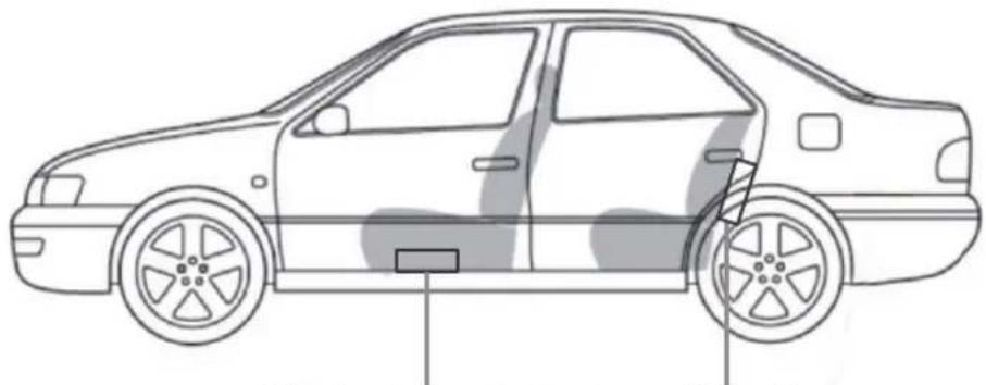
The following illustration shows a typical installation. To get the best performance from your AUDIO amplifiers, we strongly recommend that installation be entrusted to a qualified professional. Although these instructions explain how to install AUDIO amplifiers in a general sense, they do not show specific installation methods that may be required for your particular vehicle. If you do not have the necessary tools or experience, do not attempt the installation yourself. Instead, please ask your authorized BOSS car audio dealer about professional installation.
natural_image
Side profile line drawing of a sedan car with visible front wheel and side panel (no text or symbols)Under Front Seat and Under Rear Seat and/or Behind Rear Seat
- Disconnect the negative (-) lead from your vehicle's battery.
- At the installation sites, locate and make a note of all fuel lines, hydraulic brake lines, vacuum lines and electrical wiring. Use extreme caution when cutting or drilling in and around these areas.
- Choose a safe mounting location away from moisture.
- Make sure, there is sufficient air circulation at the mounting location for the amplifier to cool itself.
- Mount the amplifier such as under the front seat, using the supplied hardware.
Installation
POWER SUPPLY:
flowchart
graph TD
    A["50 A fuse"] --> B["(To an accessory terminal)"]
    B --> C["Car battery"]
    B --> D["Ignition switch"]
    D --> E["Remote turn-on line"]
    E --> F["car receiver"]
    G["To metallic body or chassis"] --> H["+"]
    I["Not included with this unit."] --> J["*"]
    K["12V"] --> L["Ground"]
CAUTION:
To prevent short circuits while making connections, keep the battery's negative terminal disconnected.
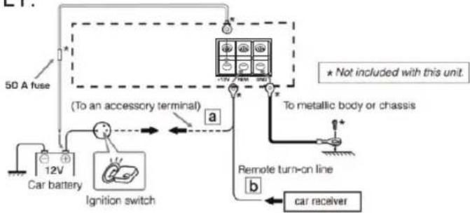
- When using a power cord, be sure to place the 50A fuse near the battery as show.
- Connect the lead wire (purchased separately) through which power is supplied directly to the battery's “⊕” terminal only after all the other connections have been made.
The lead wire connected to the +B terminal of this unit should have a cross-section of more than 5mm^2 or 8 Gauge. Be sure to use a ring terminal (optional) for secure connection.
- If you have any questions regarding the thickness of the power cord, etc., consult your nearest AUDIO dealer.
When connecting a unit without a remote lead (a), connect to the accessory circuit of the car which is activated by the ignition switch. In this case, noise may occur when the car receiver is turned on or off. To avoid this noise, do not turn on or off the car receiver itself. You can turn on or off the car receiver along with the on/off operation of the ignition switch.
If you use car receiver with a remote lead (b), connect to the REM terminal on this unit.
If the PROTECT LED glows red, it indicates amplifier in protection mode. In normal status, the POWER LED glows green. Please ensure correct speaker wiring and connections.
BEFORE CONNECTING: Securely connect all the parts. If the connections are loose, due to contact resistance etc., heat will break out and may cause an accident. Secure and cover the cords with insulating tape and run them under the car mats.
Terminal Connections
natural_image
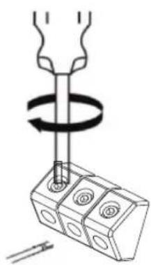
Diagram of a mechanical assembly with a rotating shaft and base components (no text or symbols)When making the terminal connections...
Properly fix the terminal with the screw provided by turning it in the direction as illustrated.
NOTE:
When you tighten the screw, make sure that the screw is securely fixed in place to prevent disconnection of the terminal. Avoid over-tightening as it may cause damage to the screw or its head slot.
Controls
LOW LEVEL INPUTS
Choose the correct length and style of RCA patch cables for your needs. Better RCA's usually have gold plated connectors and multiple layers of shielding for better noise rejection(consult your dealer).
Be careful when running your RCA patch cables. Car environments are notorious for poorly insulated wires. This means that hiss, engine noise, and fan noise can easily be picked up through. RCA cables if run incorrectly. Avoid running your RCA's near large wire looms or electric fans if possible. Run your patch cables on the opposite side of the vehicle as you did the power wire. Be sure to check for correct balance(red is right and black or white is left).
HIGH LEVEL INPUTS
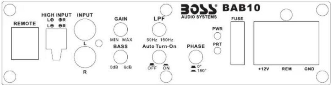
Use the high level inputs only if your audio source unit does not have low level outputs. These inputs may be tapped to the closest left and right speaker wires available for greater convenience.
HIGH INPUT AUTO TURN ON
When the high input switch is pressed. Power terminal REM is disconnected. The power amplifier can be started when the CD player is turned on.
GAIN CONTROL
This control allows you to match the input level of the amplifier to the output level of your source unit. Matching the input can be accomplished in three simple steps:
Turn gain control all the way down.
Turn on the source unit and adjust it to 2/3 of the max volume.
Adjust the gain control until desired volume is achieved without audible distortion.
Remember, the gain control is not a volume knob. Ignoring the three steps above may leave you with damaged speakers and probably a damaged amplifier.
Controls
AUTO POWER ON WITH SMART SENSE
The AUTO POWER ON feature works only with high level input.
Amplifier will detect high input signal automatically. Kindly make sure that REM connection is not connected while using SMART SENSE POWER ON feature.
PHASE CONTROL :
Set the phase control switch to select phase of the amplifier output signal 0^180^
HIGH INPUT AUTO TURN ON:
When the high input is connected, the REM is disconnected, and the amplifier can be automatically turned on.
SIGNAL INPUTS:
These amplifiers have two different types of inputs: Low level Input through RCA jack and High Level Input through a four-pin modular connector. Low level inputs provide an exceptionally clean sound from a source unit through RCA jacks. High level inputs make your amplifier virtually adaptable to any source unit with the use of speaker outputs. High level inputs should only be used when RCA outputs are not available. Under no circumstances should both low level and high level inputs be used simultaneously.
REMOTE GAIN :
User can use external remote control to imitate function of gain control knob
BASS BOOST :
For adding low bass response, rotate the Knob clockwise to add 0dB-6dB of boost centering around 50Hz
LOW PASS FILTER :
Rotate this Knob clockwise to set the required low frequency response from 50Hz to 150Hz
Troubleshooting
For more details, consult BOSS Authorized Service Center BOSS dealer
THE POWER LED DOES NOT LIGHT
- Check if the fuse is blown.
- Check if the ground lead is connected securely to a metal part of the car.
- Make sure that the equipment connected to this unit is turned on.
- Use a relay if your system employs too many amplifiers.
- Confirm the battery voltage(11V to 16V).
THE PROTECT LED GLOWS RED AND/OR THE UNIT HEATS UP ABNORMALLY
Leave the unit turned off for a while as it cools down.
NO SOUND IS HEARD
- Check if the amplifier is powered on(POWER LED glows green)
- Is the remote turn-on line lead connected correctly
- Are RCA pin cords connected to the LOW INPUT jacks
- Is the speaker input connector from the receiver connected to the HIGH INPUT terminal.
- Is this amplifier grounded
- ALTERNATOR NOISE IS HEARD.
- Keep the power connecting leads away from the RCA pin cords.
- Keep the RCA pin cords away from other electrical cables in the car.
- Check in High Level Input connector ground wire is properly grounded to metal part of the car.
- Check head unit body is properly grounded with metal part of the car.
- Check if the negative speaker leads are touching the car hassis.
- Check if the noise originates in the receiver.
- Replace the plugs or use plugs with load resistors.
- Connect a bypass capacitor across the accessory switches(horn, fan, etc.).
NOISE WHEN CONNECTED TO AM(MW/LW) TUNER Move the power leads away from the antenna(aerial) lead.
DISTORTED AUDIO
- Check if INPUT LEVEL is set properly.
- Check if Amplifier of Source unit is defective.
BOSS®
AUDIO SYSTEMS
BOSS Audio Systems
3451 Lunar Court - Oxnard, CA 93030
www.bossaudio.com
800-999-1236 US Toll-free
805-751-4853 Customer Service
Tech Support: www.bossaudio.com/support


- For Safety
- Cautions and Notes
- Specifications
- Installation
- PLACEMENT:
- POWER SUPPLY:
- CAUTION:
- Terminal Connections
- NOTE:
- Controls
- LOW LEVEL INPUTS
- HIGH LEVEL INPUTS
- HIGH INPUT AUTO TURN ON
- GAIN CONTROL
- AUTO POWER ON WITH SMART SENSE
- PHASE CONTROL :
- HIGH INPUT AUTO TURN ON:
- SIGNAL INPUTS:
- REMOTE GAIN :
- BASS BOOST :
- LOW PASS FILTER :
- Troubleshooting
- THE POWER LED DOES NOT LIGHT
- THE PROTECT LED GLOWS RED AND/OR THE UNIT HEATS UP ABNORMALLY
- NO SOUND IS HEARD
- DISTORTED AUDIO
- BOSS®
- AUDIO SYSTEMS
Brand : BOSS
Model : BAB10
Category : Subwoofer