
BA-235 - Blender TOA - Free user manual and instructions
Find the device manual for free BA-235 TOA in PDF.


| Product Type | Power Amplifier |
| Model | BA-235 |
| Brand | TOA |
| Output Power | 35 W (rated) |
| Frequency Response | 50 Hz - 20 kHz |
| Total Harmonic Distortion | 0.5% or less at 1 kHz, rated output |
| Power Source | 120 V AC, 60 Hz |
| Power Consumption | 90 W (rated output) |
| Dimensions | 210 (W) x 94.3 (H) x 265 (D) mm (8.27" x 3.71" x 10.43") |
| Weight | 4 kg (8.82 lb) |
| Input Sensitivity/Impedance | Line input: 0 dB/+4 dB selectable, 10 kΩ, unbalanced |
| Speaker Outputs | 4 Ω, 25 V (18 Ω load), 70 V (140 Ω load), removable terminal block |
| Bridge Output | Parallel to Line input, removable terminal block |
| Tone Controls | Bass: ±10 dB at 100 Hz; Treble: ±10 dB at 10 kHz |
| Indicators | Power (blue), Signal level (green), Peak (red) |
| Remote Volume | External 10 kΩ linear taper potentiometer |
| Protection | Thermal shutdown, circuit breaker, limiter |
| Operating Temperature | 0 to 35 °C (32 to 95 °F) |
| Operating Humidity | 35% to 80% RH (no condensation) |
| Rack Mounting | Optional MB-25B-BK or MB-25B-J brackets |
| Accessories Included | YA-920 Volume control cover, removable terminal plugs (2P x3, 4P x1) |
Frequently Asked Questions - BA-235 TOA
User questions about BA-235 TOA
0 question about this device. Answer the ones you know or ask your own.
Ask a new question about this device
Download the instructions for your Blender in PDF format for free! Find your manual BA-235 - TOA and take your electronic device back in hand. On this page are published all the documents necessary for the use of your device. BA-235 by TOA.
USER MANUAL BA-235 TOA
POWER AMPLIFIERS BA-235
BA-260
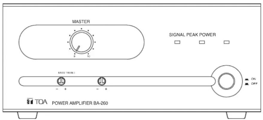
This figure represents the BA-260.
TABLE OF CONTENTS
- IMPORTANT SAFETY INSTRUCTIONS .... 2
- SAFETY PRECAUTIONS .... 3
- GENERAL DESCRIPTION ...... 5
- FEATURES 5
- NOMENCLATURE AND FUNCTIONS
Front 5
Rear 6
- CONNECTIONS
6.1. Removable Terminal Plug Connection 7
6.2. Input Connections ...... 7
6.3. Output Connections 8
- REMOTE VOLUME CONTROL
CONNECTION 8
- 2-CHANNEL BROADCAST ...... 9
- OPERATION 9
- INSTALLATION PRECAUTIONS ...... 9
- RACK MOUNTING BRACKET ATTACHMENT .... 10
- VOLUME SETTING 11
- VOLUME CONTROL COVER ...... 11
- BLOCK DIAGRAM 11
- DIMENSIONAL DIAGRAM 12
- SPECIFICATIONS 12
Accessories 12
Optional products 12
1. IMPORTANT SAFETY INSTRUCTIONS
- Read these instructions.
- Keep these instructions.
- Heed all warnings.
- Follow all instructions.
- Do not use this apparatus near water.
- Clean only with dry cloth.
- Do not block any ventilation openings. Install in accordance with the manufacturer's instructions.
- Do not install near any heat sources such as radiators, heat registers, stoves, or other apparatus (including amplifiers) that produce heat.
- Do not defeat the safety purpose of the polarized or grounding-type plug. A polarized plug has two blades with one wider than the other. A grounding type plug has two blades and a third grounding prong. The wide blade or the third prong are provided for your safety. If the provided plug does not fit into your outlet, consult an electrician for replacement of the obsolete outlet.
- Protect the power cord from being walked on or pinched particularly at plugs, convenience receptacles, and the point where they exit from the apparatus.
- Only use attachments/accessories specified by the manufacturer.
- Use only with the cart, stand, tripod, bracket, or table specified by the manufacturer, or sold with the apparatus. When a cart is used, use caution when moving the cart/apparatus combination to avoid injury from tip-over.

- Unplug this apparatus during lightning storms or when unused for long periods of time.
- Refer all servicing to qualified service personnel. Servicing is required when the apparatus has been damaged in any way, such as power-supply cord or plug is damaged, liquid has been spilled or objects have fallen into the apparatus, the apparatus has been exposed to rain or moisture, does not operate normally, or has been dropped.
INSTRUCTIONS ESSENTIELLES POUR LA SÉCURITÉ
- Before installation or use, be sure to carefully read all the instructions in this section for correct and safe operation.
- Be sure to follow all the precautionary instructions in this section, which contain important warnings and/or cautions regarding safety.
• After reading, keep this manual handy for future reference.
Safety Symbol and Message Conventions
Safety symbols and messages described below are used in this manual to prevent bodily injury and property damage which could result from mishandling. Before operating your product, read this manual first and understand the safety symbols and messages so you are thoroughly aware of the potential safety hazards.

The exclamation point within an equilateral triangle is intended to alert the user to the presence of important operation and maintenance (servicing) instruction in the literature accompanying the appliance.

Indicates a potentially hazardous situation which, if mishandled, could result in death or serious personal injury.
When Installing the Unit
- Do not expose the unit to rain or an environment where it may be splashed by water or other liquids, as doing so may result in fire or electric shock.
- Ne pas exposer l'appareil à la pluie et le protéger de tout contact avec de l'eau ou d'autres liquides afin d'éviter un incendie ou une électrocution.
- Use the unit only with the voltage specified on the unit. Using a voltage higher than that which is specified may result in fire or electric shock.
- Do not cut, kink, otherwise damage nor modify the power supply cord. In addition, avoid using the power cord in close proximity to heaters, and never place heavy objects -- including the unit itself -- on the power cord, as doing so may result in fire or electric shock.
- Avoid installing or mounting the unit in unstable locations, such as on a rickety table or a slanted surface. Doing so may result in the unit falling down and causing personal injury and/or property damage.
- External wiring connected to the terminals marked with requires installation by an instructed person.
- Les câbles externes branchés aux bornes marquées de doivent être installé par un technicien spécialement formé.
- The apparatus shall be connected to a mains socket outlet with a protective earthing connection.
-
L'appareil doit être branché à une prise d'alimentation avec mise à la terre de protection.
-
The socket-outlet shall be installed near the equipment and the plug (disconnecting device) shall be easily accessible.
- La prise doit être installée à proximité de l'équipement et la fiche (dispositif de déconnexion) doit être facilement accessible.
- Use the optional Rack mounting bracket MB-25B-BK or MB-25B-J when mounting the unit(s) in an equipment rack. Remove four M4 x 8 screws on both sides of the unit, and mount the bracket there using the M4 x 16 screws (supplied with the bracket) instead.
- Utilisez la patte de montage en bâti en option MB-25B-BK ou MB-25B-J pour monter l'unité en bâti. Retirez les quatre vis M4 x 8 sur les deux côtés de l'appareil, et montez la patte à l'aide des vis M4 x 16 fournies avec la patte.
When the Unit is in Use
- Should the following irregularity be found during use, immediately switch off the power, disconnect the power supply plug from the AC outlet and contact your nearest TOA dealer. Make no further attempt to operate the unit in this condition as this may cause fire or electric shock.
- If you detect smoke or a strange smell coming from the unit
- If water or any metallic object gets into the unit
- If the unit falls, or the unit case breaks
- If the power supply cord is damaged (exposure of the core, disconnection, etc.)
- If it is malfunctioning (no tone sounds.)
- To prevent a fire or electric shock, never open nor remove the unit case as there are high voltage components inside the unit. Refer all servicing to your nearest TOA dealer.
Indicates a potentially hazardous situation which, if mishandled, could result in moderate or minor personal injury, and/or property damage.
When Installing the Unit
- Never plug in nor remove the power supply plug with wet hands, as doing so may cause electric shock.
- When unplugging the power supply cord, be sure to grasp the power supply plug; never pull on the cord itself. Operating the unit with a damaged power supply cord may cause a fire or electric shock.
- When moving the unit, be sure to remove its power supply cord from the wall outlet. Moving the unit with the power cord connected to the outlet may cause damage to the power cord, resulting in fire or electric shock. When removing the power cord, be sure to hold its plug to pull.
- Do not block the ventilation slots in the unit's cover. Doing so may cause heat to build up inside the unit and result in fire.
- Avoid installing the unit in humid or dusty locations, in locations exposed to the direct sunlight, near the heaters, or in locations generating sooty smoke or steam as doing otherwise may result in fire or electric shock.
-
To avoid electric shocks, be sure to unplug the unit's power supply cord when connecting speakers.
-
Be sure to follow the instructions below when rack-mounting the unit. Failure to do so may cause a fire or personal injury.
- Install the equipment rack on a stable, hard floor. Fix it with anchor bolts or take other arrangements to prevent it from falling down.
- When connecting the unit's power cord to an AC outlet, use the AC outlet with current capacity allowable to the unit.
- No rack-mounting screws are supplied with the unit. Separately prepare the appropriate screws for the rack.
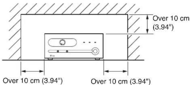
- Keep the amplifier over 10 cm (3.94") away from objects that may obstruct air flow to prevent the unit's internal temperature rise.
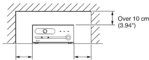
Over 10 cm (3.94") Over 10 cm (3.94")
When the Unit is in Use
- Do not place heavy objects on the unit as this may cause it to fall or break which may result in personal injury and/or property damage. In addition, the object itself may fall off and cause injury and/or damage.
- Make sure that the volume control is set to minimum position before power is switched on. Loud noise produced at high volume when power is switched on can impair hearing.
- Do not operate the unit for an extended period of time with the sound distorting. This is an indication of a malfunction, which in turn can cause heat to generate and result in a fire.
- If dust accumulates on the power supply plug or in the wall AC outlet, a fire may result. Clean it periodically. In addition, insert the plug in the wall outlet securely.
- Switch off the power, and unplug the power supply plug from the AC outlet for safety purposes when cleaning or leaving the unit unused for 10 days or more. Doing otherwise may cause a fire or electric shock.
The lighting flash with arrowhead symbol, within an equilateral triangle, is intended to alert the user to the presence of uninsulated "dangerous voltage" within the product's enclosure that may be of sufficient magnitude to constitute a risk of electric shock to persons.
The BA-235 (35 W) and BA-260 (60 W) are Power Amplifiers for background music and general announcement. These units are suited for use in bars, retail stores, and banquet rooms. When used in conjunction with the optional mixer amplifier BG-220 (20 W) or BG-235 (35 W), 2-channel broadcast can be made.
4. FEATURES
- Remote master volume control using an external volume control.
- Supplied volume control cover prevents accidental operation of the Master volume knob.
- Front operable bass and treble controls.
Also front panel recessed knobs help to prevent accidental operation. - Removable input/output terminal blocks facilitate installation and maintenance.
Besides, RCA jacks provided for LINE input.
5. NOMENCLATURE AND FUNCTIONS
[Front]
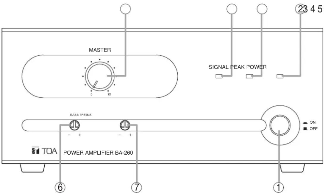
This figure represents the BA-260.
1. Power switch
Power is switched on and off with each depression of this switch.
2. Power indicator
Lights blue when the Power switch (1) is switched on.
3. Master volume control
Adjusts the gain of the Line input.
Turn the knob clockwise to increase the level and counterclockwise to decrease it.
4. Signal level indicator
Lights green when audio signals are output from the speaker output terminal.
5. Peak indicator
Lights red if output signals approach clipping level. If steady lit, turn down the Master volume control until the indicator flashes intermittently.
6. Bass control
Turn the control clockwise to increase bass level and counterclockwise to decrease it.
The center position of the control provides flat frequency response.
7. Treble control
Turn the control clockwise to increase treble level and counterclockwise to decrease it.
The center position of the control provides flat frequency response.
[Rear]
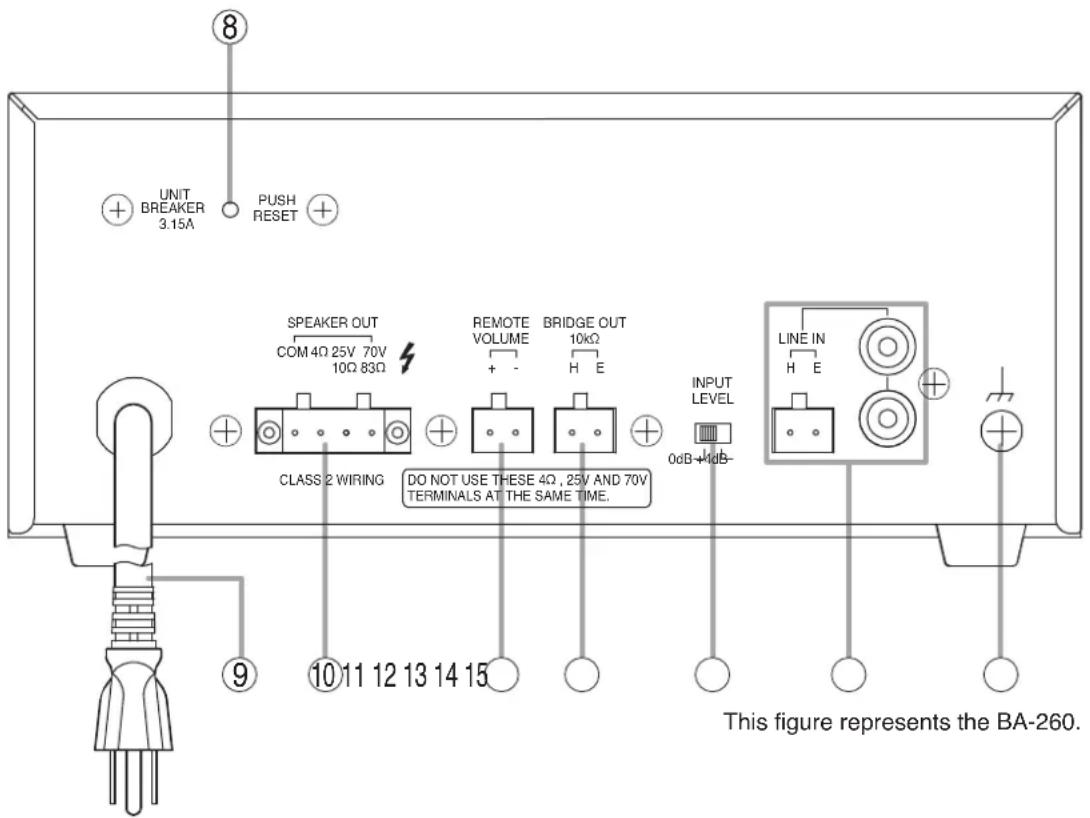
8. Breaker
Cuts off the AC power supply from the AC outlet if the power current exceeds the allowable value. Note
The yellow button in the breaker pops out to indicate that the breaker has tripped. After turning off the power and eliminating the cause of the breaker trip, press the button to reset the breaker.
9. AC power cord
Connect to an AC wall outlet.
10. Speaker output terminal
4 Ω, 25 V and 70 V outputs, removable terminal block.
Connects to speakers.
Refer to p. 7.
11. Remote volume terminal
Removable terminal block.
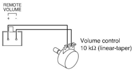
Connecting a 10 kΩ linear taper volume control across these terminals will allow remote control of speaker output level.
12. Bridge output terminal
Removable terminal block.
This connector is internally connected in parallel to the Line input connectors (14).
Connect to the other amplifier's input.
13. Input level selector switch
Selects either 0 dB or +4 dB for the line input sensitivity level.
14. Line input terminals
10 kΩ, 0 dB*/+4 dB* selectable (see item 13), unbalanced, removable terminal block and RCA jacks (Upper and lower RCA jacks are internally, passively mixed.) (* 0 dB = 1 V)
These connectors are internally connected in parallel to the Bridge output connector (12).
Connect to the MOH output or Line output of the optional BG-220 or BG-235, or the Line output of a sound source equipment such as a CD player.
15. Functional ground terminal
Hum noise may be generated when external equipment is connected to the unit. Connecting this terminal to the functional ground may reduce the hum noise.
Note: This terminal is not for protective earth.
6. CONNECTIONS
6.1. Removable Terminal Plug Connection
Notes
- Avoid soldering cable conductor, as contact resistance may increase when the cable is tightened and the solder is crushed, possibly resulting in an excessive rise in joint temperatures.
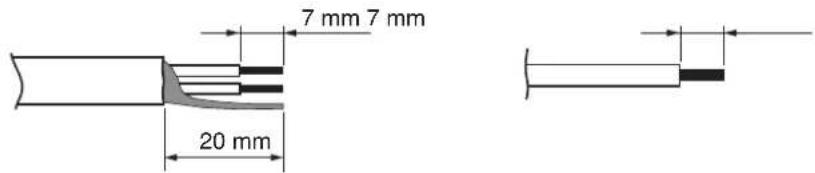
- Use cables of AWG 12 – 24.
[Cable end treatment]
2-core shielded cable Solid cable and stranded cable
[Wiring Procedure]
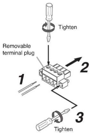
Step 1. Wiring the supplied removable terminal plug.
1-1. Loosen the terminal screws to insert the wire.
1-2. Tighten the terminal screws.
Ensure that the wire does not break free when pulled. If the wire does pull free, repeat the connection procedure from the start.
Step 2. Insert the wired terminal plug into the corresponding terminal block in the unit's rear panel.
Step 3. Tighten the fixing screws. (Speaker output terminals only)
Notes
- Do not reverse Steps 1 and 2. Poor contact may result if force is applied to the unit's internal circuit board pins while the terminal screws are being tightened.
- Use an appropriate type screwdriver for terminal plug wiring.
6.2. Input Connections
6.2.1. Line input connections

Upper and lower RCA jacks are internally, passively mixed.
[Input level selection]
Input sensitivity can be switched to either 0 dB or +4 dB depending on the output level of the input equipment.
INPUT LEVEL
![TOA BA-235 - [Input level selection] - 1](/content/2026/05/953070/images/f22eaa1bb7e40f31fd872a71c4b0049e0d737cf321182882aaa302f58f81fccc.jpg)
6.3. Output Connections
6.3.1. Speaker connections
Each amplifier has 3 speaker outputs: 4 Ω, 25 V, and 70 V. Use only one of these outputs for connection. Class 2 wiring may be used.
Note: Impedances in the figures below represent total speaker load impedance.
Speaker output terminal
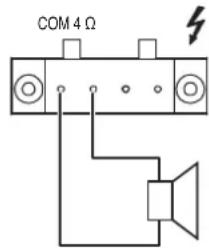
Speaker output terminal
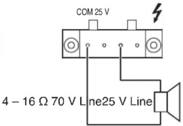
Speaker output terminal
25 V LINE
Total impedance
18 Ω (BA-235)
10 Ω (BA-260)
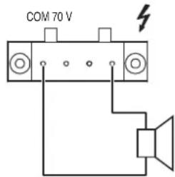
70 V LINE Total impedance 140 Ω (BA-235) 83 Ω (BA-260)

WARNING
The terminals marked with the symbol are hazardous live. The external wiring to these terminals requires installation by an instructed person.
6.3.2. Bridge output connection
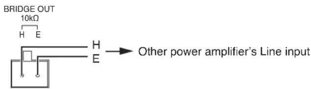
7. REMOTE VOLUME CONTROL CONNECTION
The external volume control can remotely adjust the signal level at post-master volume control. When performing the remote volume control, adjust the master volume control in advance noting that its setting limits the maximum signal level adjustable with the volume control. Be sure to avoid turning fully down the master volume control.
Notes
- Negative terminal should not be grounded. Never connect it to the unit's chassis nor other circuit ground.
- Only a volume control can be connected to these terminals.
8. 2-CHANNEL BROADCAST
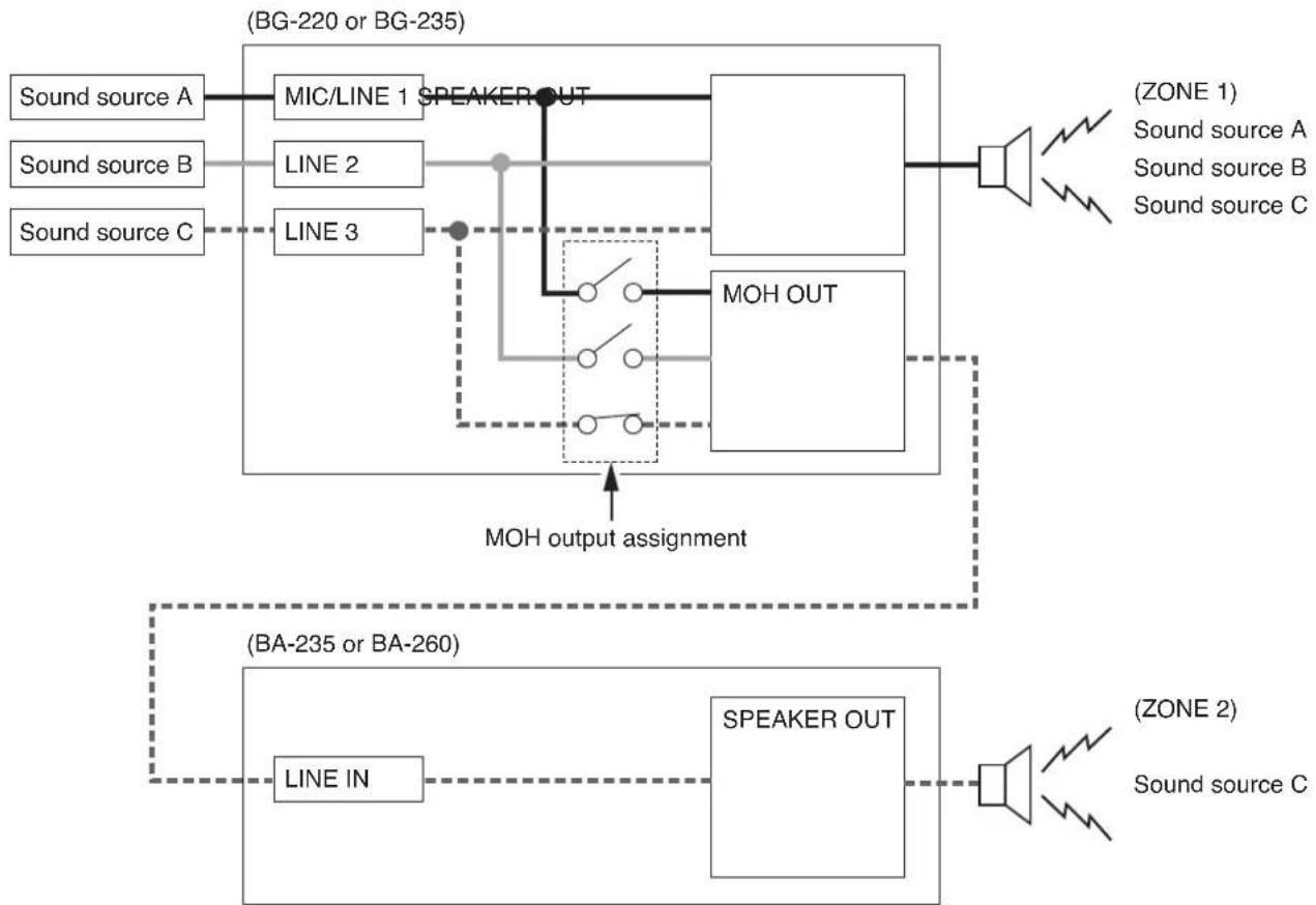
Each individual input of the optional BG-220 (20 W) and BG-235 (35 W) can be output to the MOH output. 2-channel broadcast can be performed by connecting the MOH output to the unit's LINE input.
(Example)
When MIC/LINE 1, LINE 2, and LINE 3 input signals are output to the Zone 1, and LINE 3 input signals to the Zone 2.
flowchart
graph TD
    A["Sound source A"] --> B["MIC/LINE 1 SPEAKER OUT"]
    C["Sound source B"] --> D["LINE 2"]
    E["Sound source C"] --> F["LINE 3"]
    B --> G["MOH OUT"]
    D --> G
    F --> G
    G --> H["Speaker Out"]
    I["(BA-235 or BA-260)"] --> J["LINE IN"]
    J --> K["SPEAKER OUT"]
    L["(ZONE 1) Sound source A"] --> M["Speaker"]
    N["(ZONE 2) Sound source C"] --> O["Speaker"]
    P["(ZONE 1) Sound source A"] --> Q["Speaker"]
    R["(ZONE 2) Sound source C"] --> S["Speaker"]
    T["(ZONE 1) Sound source A"] --> U["Speaker"]
    V["(ZONE 2) Sound source C"] --> W["Speaker"]
    X["(ZONE 1) Sound source A"] --> Y["Speaker"]
    Z["(ZONE 2) Sound source C"] --> AA["Speaker"]
    AB["(ZONE 1) Sound source A"] --> AC["Speaker"]
    AD["(ZONE 2) Sound source C"] --> AE["Speaker"]
    AF["(ZONE 1) Sound source A"] --> AG["Speaker"]
    AH["(ZONE 2) Sound source C"] --> AI["Speaker"]
    AJ["(ZONE 1) Sound source A"] --> AK["Speaker"]
    AL["(ZONE 2) Sound source C"] --> AM["Speaker"]
    AN["(ZONE 1) Sound source A"] --> AO["Speaker"]
    AP["(ZONE 2) Sound source C"] --> AQ["Speaker"]
    AR["(ZONE 1) Sound source A"] --> AS["Speaker"]
    AT["(ZONE 2) Sound source C"] --> AU["Speaker"]
    AV["(ZONE 1) Sound source A"] --> AW["Speaker"]
    AX["(ZONE 2) Sound source C"] --> AY["Speaker"]
    AZ["(ZONE 1) Sound source A"] --> BA["Speaker"]
    BB["(ZONE 2) Sound source C"] --> BC["Speaker"]
    BD["(ZONE 1) Sound source A"] --> BE["Speaker"]
    BF["(ZONE 2) Sound source C"] --> BG["Speaker"]
    BH["(ZONE 1) Sound source A"] --> BI["Speaker"]
    BJ["(ZONE 2) Sound source C"] --> BK["Speaker"]
    BL["(ZONE 1) Sound source A"] --> BLA["Speaker"]
    BM["(ZONE 2) Sound source C"] --> BN["Speaker"]
9. OPERATION
After completing all connections, turn on the power switch, and check to confirm that the power indicator lights.
Note
When the heat sink temperature exceeds 105 ^ ( 221 ^ ), the protection circuit begins to operate to disconnect the output from the circuit. The disconnected output is automatically restored as soon as the temperature returns to the normal operating range.
10. INSTALLATION PRECAUTIONS

CAUTION
Keep the amplifier over 10 cm (3.94") away from objects that may obstruct air flow to prevent the unit's internal temperature rise.
11. RACK MOUNTING BRACKET ATTACHMENT
To mount the BA-235 (BA-260) in a standard 19" equipment rack, use the optional MB-25B-BK or MB-25B-J Rack Mounting Kit.
Before attaching the rack mounting bracket, remove each 2 frontmost screws on both sides of the unit. These removed screws are not used for rack mounting.
Notes
- Rack mounting screws are not supplied with the unit. Use the screws that are appropriate for the rack.
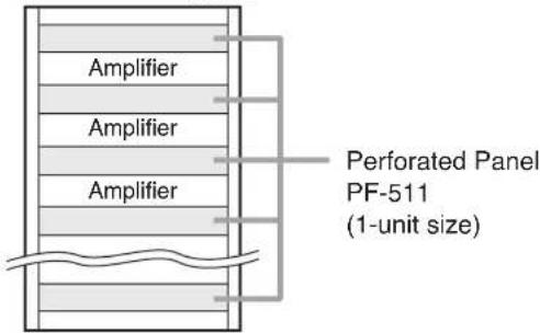
- When mounting the unit in an equipment rack, the inside of the rack must be sufficiently ventilated.
To achieve sufficient ventilation, also mount the optional PF-511 Perforated Panel (1U*):
(1) at the top and the bottom of the rack, and (2) above and below the unit.
* 1U size = 44.5 mm or 1.75" (reference size)
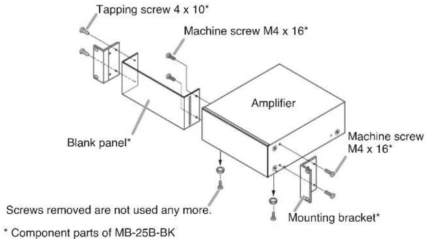
[MB-25B-BK]
Remove 4 plastic feet on the bottom surface.
Note that these removed screws are not used.
Attach the MB-25B-BK to the unit using the supplied 4 screws.
[MB-25B-J]
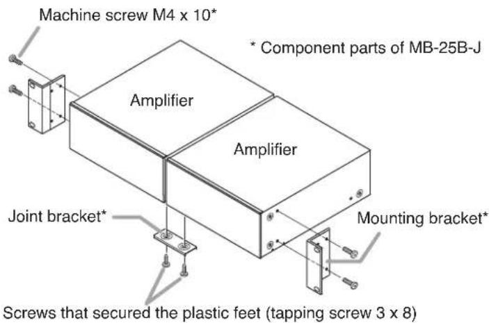
The MB-25B-J is designed to mount two BA-235 (BA-260) units in a single rack.
When using this bracket, remove 4 plastic feet on the bottom surface of each unit and joint the 2 units with a joint bracket, as illustrated below.
Then attach the mounting brackets using the supplied 4 screws.
12. VOLUME SETTING
Output levels are adjustable with the Master volume control. For music play or announcement, adjust the volume control so that the signal indicator lights intermittently. Note that the sound quality is downgraded when the peak indicator remains lit.
13. VOLUME CONTROL COVER
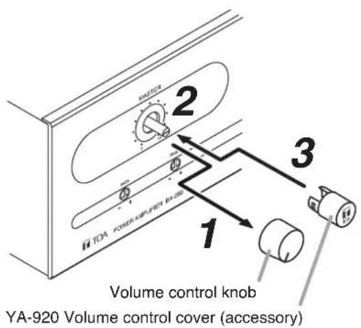
To prevent the accidental change of the Master volume control setting on the front panel, it is recommended to replace its control knob with the supplied YA-920 Volume Control Cover. Follow the procedure below for its replacement.
Step 1. Remove the control knob.
Step 2. Adjust the Master volume control (without knob) to an appropriate level.
Step 3. Attach the YA-920 onto the control.
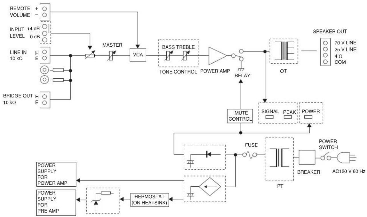
14. BLOCK DIAGRAM
flowchart
graph TD
    A["INPUT +4 dB LEVEL 0 dB"] --> B["REMOTE VOLUME"]
    B --> C["LINE IN 10 kΩ"]
    C --> D["BRIDGE OUT 10 kΩ"]
    D --> E["H E"]
    E --> F["MASTER"]
    F --> G["VCA"]
    G --> H["BASS TREBLE"]
    H --> I["TONE CONTROL POWER AMP"]
    I --> J["RELAY"]
    J --> K["OT"]
    K --> L["SPEAKER OUT 70 V LINE 25 V LINE 4 Ω COM"]
    K --> M["MUTE CONTROL"]
    M --> N["FUSE"]
    N --> O["POWER SWITCH AC120 V 60 Hz"]
    O --> P["POWER SUPPLY FOR POWER AMP"]
    O --> Q["POWER SUPPLY FOR PRE AMP"]
    P --> R["THERMOSTAT (ON HEATSINK)"]
    Q --> R
    R --> S["PT"]
    S --> T["BREAKER"]
    T --> U["AC120 V 60 Hz"]
15. DIMENSIONAL DIAGRAM
Unit: mm (in)
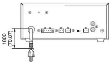
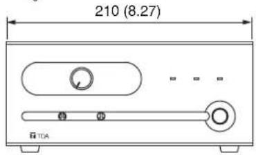
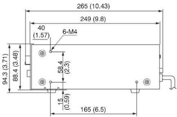
16. SPECIFICATIONS
| Model No. BA-235 BA-260 | |||
| Power Source 120 V AC, 60 Hz | |||
| Rated Output 35 W 60 W | |||
| Power Consumption 90 W (rated output) 130 W (rated output)52 W (based on cULus standards) 66 W (based on cULus standards) | |||
| Frequency Response 50 Hz - 20 kHz | |||
| Total Harmonic Distortion 0.5% or less, at 1 kHz, rated output | |||
| Input Line input | |||
| Input Sensitivity/Impedance removable terminal block or RCA jacks | Line input: 0 dB*/+4 dB* (selectable), 10 kΩ, unbalanced, balanced, removable terminal block | ||
| Output | Speaker Output | 4 Ω, 25 V (18 Ω) and 70 V (140 Ω)balanced, removable terminal block | 4 Ω, 25 V (10 Ω) and 70 V (83 Ω)balanced, removable terminal block |
| Bridge Output | Parallel in Line input, removable terminal block | ||
| Output Regulation (1 kHz) | Under 2 dB, no load to full load | ||
| S/N Ratio | Line input: Over 80 dB(Band Pass: 20 Hz - 20 kHz, Tone Controls: Centered) | ||
| Tone Control | Bass: ±10 dB at 100 Hz, Treble: ±10 dB at 10 kHz | ||
| Control | Master gain controlBass tone control, Treble tone controlInput level selector switchRemote volume controlPower ON/OFF switch | ||
| Indicator | Power LED, Signal level LED, Peak LED | ||
| Other Feature | Automatic electronic drive limiter | ||
| Operating Temperature | 0 to 35 °C (32 to 95 °F) | ||
| Operating Humidity | 35 % to 80 % RH (no condensation) | ||
| Finish | Panel: ABS resin, blackCase: Steel plate, black, paint | ||
| Dimensions | 210 (w) x 94.3 (h) x 265 (d) mm (8.27" x 3.71" x 10.43") | ||
| Weight | 4 kg (8.82 lb) | 4.6 kg (10.14 lb) | |
* 0 dB = 1 V
Note: The design and specifications are subject to change without notice for improvement.
- Accessories
YA-920 Volume control cover 1
Removable terminal plug (2P) 3
Removable terminal plug (4P) .... 1
- Optional products
Rack mounting brackets : MB-25B-BK, MB-25B-J

- POWER AMPLIFIERS BA-235
- BA-260
- TABLE OF CONTENTS
- IMPORTANT SAFETY INSTRUCTIONS
- INSTRUCTIONS ESSENTIELLES POUR LA SÉCURITÉ
- Safety Symbol and Message Conventions
- When Installing the Unit
- When the Unit is in Use
- FEATURES
- NOMENCLATURE AND FUNCTIONS
- Power switch
- Power indicator
- Master volume control
- Signal level indicator
- Peak indicator
- Bass control
- Treble control
- Breaker
- AC power cord
- Speaker output terminal
- Remote volume terminal
- Bridge output terminal
- Input level selector switch
- Line input terminals
- Functional ground terminal
- CONNECTIONS
- Removable Terminal Plug Connection
- Notes
- [Cable end treatment]
- [Wiring Procedure]
- Input Connections
- Line input connections
- [Input level selection]
- Output Connections
- Speaker connections
- WARNING
- Bridge output connection
- REMOTE VOLUME CONTROL CONNECTION
- 2-CHANNEL BROADCAST
- OPERATION
- Note
- INSTALLATION PRECAUTIONS
- CAUTION
- RACK MOUNTING BRACKET ATTACHMENT
- [MB-25B-BK]
- [MB-25B-J]
- VOLUME SETTING
- VOLUME CONTROL COVER
- BLOCK DIAGRAM
- DIMENSIONAL DIAGRAM
- SPECIFICATIONS
- - Accessories
- - Optional products
Brand : TOA
Model : BA-235
Category : Blender