Attero Tech Axon D2i - Uncategorized QSC - Free user manual and instructions
Find the device manual for free Attero Tech Axon D2i QSC in PDF.


| Product Type | Dante/AES67 Audio Interface with Axiom Expansion |
| Model | Attero Tech Axon D2i |
| Brand | QSC |
| Analog Inputs | 2 x Combination XLR/1/4" balanced mic/line |
| Phantom Power | +48V, software selectable per input |
| Preamp Gain Range | -8 dB to +34 dB in 1 dB steps |
| THD+N | <= 0.05% at -3 dBFS |
| Dynamic Range | >110 dB (20-22 kHz) |
| Frequency Response | 20 Hz - 20 kHz, ±1 dB |
| Network Interface | Dante/AES67 via RJ-45, 100 Mbps |
| Supported Sample Rates | 44.1, 48 (default), 88.2, 96 kHz |
| Bit Depth | 16 or 24 bits |
| Audio Latency | Minimum 1 ms |
| Power Source | PoE IEEE 802.3af Class 0 or +24V DC local |
| Power Consumption | <12 W max |
| Dimensions (W x H x D) | 1.650" x 4.200" x 2.125" |
| Weight (installed / packaged) | 0.33 lbs / 0.66 lbs |
| Mounting | Single-gang US Decora wall plate |
| Included Accessories | White and black Decora inserts, cover plates, mounting screws |
| Cleaning Instructions | Clean only with a dry cloth |
| Safety | Do not expose to rain or moisture; read all safety instructions |
| Warranty | Limited 3-year warranty from date of purchase |
| Regulatory Compliance | FCC Part 15 Class A, CE, RoHS, WEEE, REACH |
| Operating Temperature | 0 to 40°C |
| Additional Features | Axiom expansion port, status LEDs, low power mode, 3rd party UDP control |
Frequently Asked Questions - Attero Tech Axon D2i QSC
User questions about Attero Tech Axon D2i QSC
0 question about this device. Answer the ones you know or ask your own.
Ask a new question about this device
Download the instructions for your Uncategorized in PDF format for free! Find your manual Attero Tech Axon D2i - QSC and take your electronic device back in hand. On this page are published all the documents necessary for the use of your device. Attero Tech Axon D2i by QSC.
USER MANUAL Attero Tech Axon D2i QSC
Axon D2i
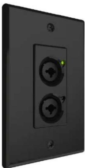
Single-Gang Dante/AES67 Audio Interface w/ Axiom Expansion
natural_image
Exterior view of a black wall-mounted electrical outlet with two circular switches and a green indicator light (no text or symbols)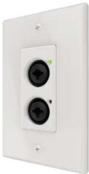
natural_image
White wall-mounted electrical outlet with two black circular switches (no text or symbols visible)User Manual
Date 6/4/2020
IMPORTANT SAFETY INSTRUCTIONS
The symbols below are internationally accepted symbols that warn of potential hazards with electrical products.

This symbol, wherever it appears, alerts you to the presence of un-insulated dangerous voltage inside the enclosure -- voltage that may be sufficient to constitute a risk of shock.

This symbol, wherever it appears, alerts you to important operating and maintenance instructions in the accompanying literature. Please read the manual.
- Read these instructions.
- Keep these instructions.
- Heed all warnings.
- Follow all instructions.
- Do not use this apparatus near water.
- Clean only with a dry cloth.
-
Do not block any ventilation openings. Install in accordance with the manufacturer's instructions.
-
Do not install near any heat sources such as radiators, heat registers, stoves, or other apparatus (including amplifiers) that produce heat.
-
Do not defeat the safety purpose of the polarized or grounding-type plug. A polarized plug has two blades with one wider than the other. A grounding type plug has two blades and third grounding prong. The wider blade or the third prong is provided for your safety. If the provided plug does not fit into your outlet, consult an electrician for replacement of the obsolete outlet.
-
Protect the power cord from being walked on or pinched particularly at plugs, convenience receptacles, and the point where they exit from the apparatus.
-
Only use attachments/accessories specified by Attero Tech by QSC
-
Use only with the cart, stand, tripod, bracket, or table specified by the manufacturer, or sold with the apparatus.
-
When a cart is used, use caution when moving the cart/apparatus combination to avoid injury from tip-over.
-
Unplug this apparatus during lightning storms or when unused for long periods of time.
-
Refer all servicing to qualified service personnel. Servicing is required when the apparatus has been damaged in any way, such as power-supply cord or plug is damaged, liquid has been spilled or objects have fallen into the apparatus, the apparatus has been exposed to rain or moisture, does not operate normally, or has been dropped.
-
This apparatus shall be connected to a mains socket outlet with a protective earthing connection.
-
When permanently connected, on all-pole mains switch with a contact separation of at least 3mm in each pole shall be incorporated in the electrical installation of the building.
-
If rack mounting, provide adequate ventilation. Equipment may be located above or below this apparatus but some equipment (like large power amplifiers) may cause an unacceptable amount of hum or may generate too much heat and degrade the performance of this apparatus.

TO REDUCE THE RISK OF FIRE OR ELECTRIC SHOCK, DO NOT EXPOSE THIS APPARATUS TO RAIN OR MOISTURE.
LIMITED THREE YEAR WARRANTY
The equipment is warranted for three years from date of purchase from QSC, LLC against defects in materials or workmanship. This warranty does not cover equipment which has been abused or damaged by careless handling or shipping. This warranty does not apply to used or demonstrator equipment. Should any defect develop, QSC, LLC will, at our option, repair or replace any defective parts without charge for either parts or labor. If QSC, LLC cannot correct the defect in the equipment, it will be replaced at no charge with a similar new item. QSC, LLC will pay for the cost of returning your equipment to you. This warranty applies only to items returned to Attero Tech, LLC, shipping costs prepaid, within five years from the date of purchase. This Limited Warranty is governed by the laws of the State of Indiana. It states the entire liability of QSC, LLC and the entire remedy of the purchaser for any breach of warranty as outlined above. NEITHER QSC, LLC NOR ANYONE INVOLVED IN THE PRODUCTION OR DELIVERY OF THE EQUIPMENT SHALL BE LIABLE FOR ANY INDIRECT, SPECIAL, PUNITIVE, CONSEQUENTIAL, OR INCIDENTAL DAMAGES ARISING OUT OF THE USE OR INABILITY TO USE THIS EQUIPMENT EVEN IF ATTERO TECH, LLC HAS BEEN ADVISED OF THE POSSIBILITY OF SUCH DAMAGES. IN NO EVENT SHALL THE LIABILITY OF QSC, LLC EXCEED THE PURCHASE PRICE OF ANY DEFECTIVE EQUIPMENT.
This warranty gives you specific legal rights. You may have additional legal rights which vary from state to state.
Note: This equipment has been tested and found to comply with the limits for a Class A digital device, pursuant to Part 15 of the FCC Rules and EN55022. These limits are designed to provide reasonable protection against harmful interference when the equipment is operated in a commercial environment. This equipment generates, use and can radiate radio frequency energy and, if not installed and used in accordance with the instruction manual, may cause harmful interference to radio communications. Operation of this equipment in a residential area is likely to cause harmful interference, in which case the user will be required to correct the interference at their own expense.
CE
Contents
1 - Overview 2
1.1 - What's in the Box 2
1.2 - Optional Extras.... 2
2 - Device Installation....2
2.1 - Mounting.... 2
2.2 - Status Reporting.... 3
3 - Device Configuration.... 3
3.1 - IP Address Setup 3
3.2 - Software Control 3
3.3 - 3^rd Party Contol 3
3.4 - Factory Reset...... 4
3.5-Firmware Updates 4
ARCHITECTS & ENGINEERS SPECIFICATION 0
Device Specifications....8
1 - Overview
natural_image
Close-up of a white wall-mounted electrical outlet with two black circular components and a small green indicator light (no text or symbols visible)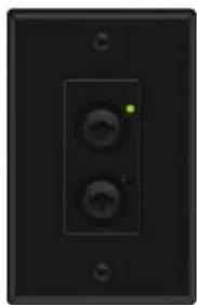
natural_image
Close-up of a black wall-mounted electrical outlet with two circular buttons and a green indicator light (no text or symbols visible)Figure 1 - D2i Front Panel
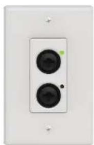
The Axon D2i Dante™/AES67 Audio Interface is a cost effective XLR/¼" - IO wall plate solution with Axiom expansion capability. The D2i features two balanced mic/line combination XLR/¼" inputs plus an Axiom expansion port for further input options. All inputs can be used simultaneously and all audio channels are mixable via onboard DSP on the Dante™/AES67 network. The D2i is designed to fit into all single gang US junction boxes, mud rings, and old work brackets. The D2i is PoE enabled, so all connectivity (power, control and data) is provided by a single CAT- 5/6 cable. The D2i's size and I/O density make it easy to put Dante™/AES67 connectivity wherever it's needed.
natural_image
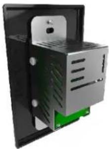
3D rendering of a black and silver electronic device housing with green base panel (no text or symbols visible)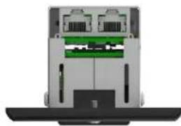
natural_image
Top-down view of a device casing with internal components and a base (no visible text or symbols)Figure 2 - D2i Rear Panel
1.1 - What's in the Box
The D2i comes supplied with the following
D2i device (P/N: 900-002375-01)
- Includes interchangeable white and black Decora-style inserts
(1) White US Single Gang Decora® cover plate w/screws
(1) Black US Single Gang Decora® cover plate w/screws
(2) Wall plate mounting screws
1.2 - Optional Extras
The following are available as options for the D2i and that may be ordered separately:
- AXIOM ML1
- AXIOM USB1
- AXIOM BT1
unBT2A
2 - Device Installation
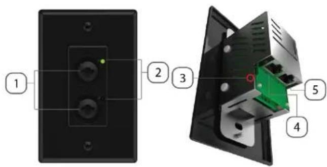
Figure 3 - Product Overview
| ID | Description |
| 1 | Combination balanced XLR/1⁄4" TRS jack(fixed pad on 1⁄4" for +24 dBu operation) |
| 2 | Status LED |
| 3 | Factory Reset access |
| 4 | DanteTM/AES67 Ethernet interface connector and indicators |
| 5 | Axiom Port |
*Note: The D2i has a label on one of the mounting flanges that shows the MAC address. This is important for initial device identification as the last 6 digits make up part of the devices default network name that is shown when the device is detected by Dante™ Controller. The full MAC address is also given on the bottom of the unit
2.1-Mounting
A typical installation will involve mounting the wall plate into a pre mounted wall box or mounting bracket. Before installation, make sure the wall box where the D2i is to be installed is pre-wired with a suitable cable back to a PoE-enabled network switch or mid-span injector. If a mid-span injector is being used, the cable should be connected to the port that supplies both Ethernet and power (refer to the devices manual if unsure which port is which).
Attach the network cable from the switch/mid-span injector to the Ethernet port of the D2i. If the switch or mid-span injector is already running and PoE is enabled, the unit will power up and the green status LED on the front of the device will turn on.
If using with an Axiom expansion device, a second suitable cable must also be installed and attached to the Axiom port on the D2i and connected Axiom device. Refer to the connected Axiom device manual to insure proper configuration for daisy-chaining.
With the cable(s) attached, carefully place the D2i into the wall box taking care to not trap the cabling. Once in place, secure it with the screws provided. Once the unit is secured in the wall box, fit the Decora plate and secure it with the screws provided.
The D2i comes in a single gang US Decora style form factor and may be mounted in most US single old and new work back boxes and mud-rings. Given the single gang size, the D2i may be mounted in larger gang boxes with other single gang form factor products to provide flexible AV system modularity where needed.
*Note: CAD drawings can be downloaded from the QSC website. Please contact QSC for any further product related information that is not accessible on the website.
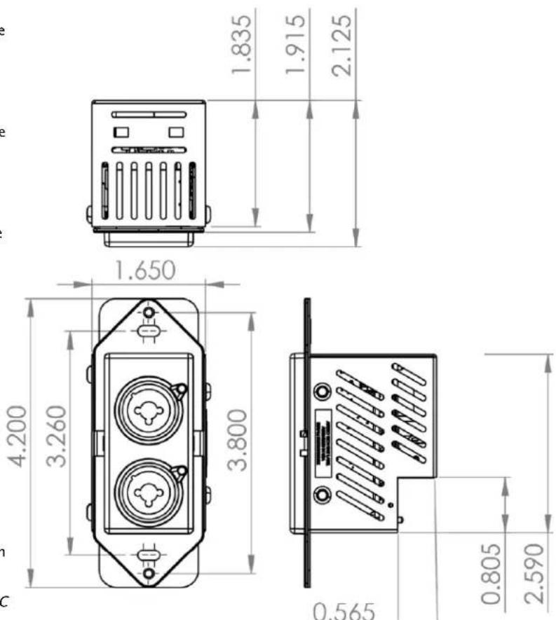
Figure 4- Dimensional Drawing
2.2- Status Reporting
The D2i is equipped with status reporting features. Upon power up, the front panel LEDs will light solid yellow then change white for 3 seconds upon succeeding. The device will then change to STATUS mode if no audio signal is present after 5 seconds. The LED states below are reflected when in STATUS mode. The status LEDs may be disabled using Attero Tech by QSC unIFY Control Panel.
| LED State | Status |
| Both Flashing Red | Critical boot error(Contact Tech Support) |
| Both Flashing White | Identify |
| Both Flashing Blue | MCU Updating |
| Both Flashing Green | Factory Reset has been triggered |
| Both Flashing Yellow | Factory Mode |
| Top White/Bottom Off | Clock Master |
| Top Off/Bottom White | Clock Synced |
When audio signal is present, the device will change to SIGNAL mode and the LEDs will show the following states. These states apply to both panel LEDs.
| LED State | Status |
| Off | No signal |
| Green | Has signal |
| Red | Clipping |
3- Device Configuration
Certain 3rd party manufacturers provide audio routing functionality from within their own configuration application. Check the applications manual/help or contact the manufacturer in question to see if this is supported. If not supported by a 3 ^rd party tool, the audio routing may be carried out using Audinate's Dante ^™ Controller. Dante ^™ Controller can be obtained from the Audinate website (www.audiante.com/) and is available for both Mac and PC. Instructions on how to use this application and about setting up routes on a Dante ^™ network can also be found on Audinate's website.
*Note: When using Dante controller, the D2i will be shown using a default device name of "D2i-#####" where '#####' is the last six characters of the devices MAC address.
3.1 - IP Address Setup
********************************************************************** IMPORTANT *******
Failure to correctly configure IP addresses will not allow an D2i device to correctly authenticate in the unIFY Control Panel software and while it will show up in Dante™ Controller, the input and output channels won't be visible and routing of audio to and from the D2i will not be possible.
***********************************************************
In order to configure a D2i both set up audio routing and to update firmware, the PC will need to be able to communicate with it over the network. While all Dante™/AES67 devices will be discovered regardless of the IP address setup on the PC, communication can only occur if the PC and the device have compatible IP addresses.
By default, D2i is set to get a dynamic IP address. As with all Dante™/AES67 devices, if the D2i device does not find a DHCP server to retrieve an IP address from, it will give itself an automatic private IP address (APIPA) instead. An APIPA is always in the range 169.254.x.y.
To ensure communication, the PC can either be set to get a dynamic IP address, or be given a static IP address in the range 169.254.x.y. The PC may require a restart for the changes to take effect.
Further information on IP setup for an audio system using Dante™ can be found in the FAQ's on the Audinate website (https://www.audinate.com/resources/faqs).
3.1 - Software Control
The D2i device parameters such as preamp control and input switching are fully supported in Attero Tech by QSC's unIFY Control Panel software (V3.5 or later). Refer to the Help documentation within the unIFY application for support.
3.2 - Automatic Low Power Mode
The D2i supports a low power mode to minimize power consumption and internal device temperatures. When enabled via unIFY Control Panel, the unit will exhibit the following behaviors.
When enabled, the D2i will enter low power mode after detecting no audio signal presence on all analog input channels for the configured inactivity timeout
When active, the front panel LEDs will blink white for one second, once a minute.
Note: Automatic Low Power Mode is off by default and is not recommended if live control/monitoring of settings is needed.
3.3 - 3 ^rd Party Contol
The D2i supports 3 ^rd party control allowing external system to manage the D2i's settings such as phantom power, mic/line gain options and control of presets. This is available to anyone to use with any device capable of sending and receiving UDP messages.
Information on the commands the D2i supports as well as details of how to use the 3 ^e party UDP interface can be found in the unIFY 3 ^rd party Software API document, available from the registered users section of the Attero Tech by QSC website (Go to www.qsc.com).
3.4 - Factory Reset
********************************************************************************************** IMPORTANT **********************************************************************************************
The factory reset returns the entire device to its factory defaults. Using this feature will mean all custom Dante™/AES67 settings and all audio power-on default settings will be cleared.
*NOTE: The factory reset is a useful way of quickly restoring communications with a device which has an unknown static IP address as a factory reset returns the device's network settings to getting a dynamic IP. Having successfully completed a factory reset of the device, setting the PC's IP address to also obtain a dynamic IP address should then allow the PC to communicate fully with that device.
The factory reset button is accessed through a small hole on the side of the unit (Figure 5) using a small screwdriver or a paperclip. A factory reset is initiated by pressing and holding this button for 5 seconds or more while the device is powered on. If done correctly, the status LED will blink green for 3 seconds then turn yellow. This indicates the D2i has entered factory mode.
If Dante™ Controller or other Dante™ device discovery software is in use, the device may show up as "Ultimo-xxxxxx". This simply indicated the device is in factory mode.
To complete the factory reset and revert back to normal operation. Simple toggle the factory reset button again with a short press and release or power cycle the device.
Having applied a successful factory reset, on the Dante™/AES67 side, customized device name and channel names will be cleared and any receive flow subscriptions will be removed. The network settings will also be reset so the device will return to retrieving an IP address dynamically.
3.5 - Firmware Updates
The D2i has the ability to be updated in the field should it be required. Updates are applied via the network using Attero Tech by QSC unIFY Control Panel's smart firmware update facility. The latest D2i SFU file is available from the QSC website.
ARCHITECTS & ENGINEERS SPECIFICATION
The Dante™/AES67 wall plate provide shall two combination XLR/ 14 :" balanced inputs. The XLR/ 14 " mic-level analog inputs shall have an attenuation range of 0 to -24dB, allowing an input full scale input signal range of 0 dBu to +24 dBu.
Each XLR input shall have adjustable gain from -8 to +34 dB with pad on the 14 " to accommodate +24 dBu line level devices. The internal digital to analog signal conversion shall support 16 and 24-bit resolution with sampling frequencies of 44.1, 48, 88.2, and 96 kHz. The default sample rate shall be 48 kHz.
The unit shall have two multi-color status and signal presence/level indicator LEDs on the front of the unit. One for each combination input jack.
The unit shall accept either +24VDC or IEEE 802.3af standard PoE from an IEEE 802.3af PoE compliant network switch or mid-span injector.
The unit shall have one 8P8C RJ45 type connector on the back side of the unit for Axiom device connection.
The unit shall support daisy chain of up to 1 Axiom device, using 1 RJ45 (8P8C style connector) for connectivity to CAT-X cabling.
The device shall support mounting the mounting of multiple units side by side in a multi-gang wall box or one unit in a single gang US wall box.
The Dante™/AES67 interface shall be compliant with the RoHS, WEEE and REACH directives.
The Dante™/AES67 interface unit shall be Compliant with the EMC/ESD requirements for FCC and CE.
The unit shall be the Attero Tech AXON D2i interface.
Device Specifications
| Analog Audio Inputs | |
| Input Type | Combination XLR/ 1⁄4" balanced mic/line connector |
| Preamp Gain | -8dB to 34dB in 1dB increments |
| THD+N | <= 0.05% at -3dBFS for all attenuation levels |
| Dynamic Range | >110 dB (20 -22 kHz) |
| Frequency Response | 20 to 20 kHz, ± 1 dB at all attenuation settings |
| Phantom Power | +48V, software selectable |
| Audio Performance | |
| EIN | -120 dBu at maximum gain |
| System THD | <= 0.05% at -3dBFS for all attenuation levels |
| Axiom | |
| Physical Layer | Analog Audio, RS-232 Control, 24V DC Power |
| Connector | 8P8C |
| Cable Quality | CAT-5e or better, UTP |
| DanteTM/AES67 Network | |
| Physical Layer | Ethernet |
| Connector (s) | RJ-45 |
| Cable Quality | CAT-5e or better, UTP |
| Transmission Speed | 100 Mbps |
| Supported Bit Rates | 16, 24 |
| Supported Sample Rates | 44.1kHz, 48kHz (default), 88.2kHz, 96kHz |
| Minimum Audio Latency | 1ms |
| AES67 Support | AES67, SAP based stream discovery |
| Power Specifications | |
| PoE Power | 802.3af Class 0 |
| Power Consumption | < 12W Max |
| Local Power | +24V DC |
| Physical Dimensions | |
| Width | 1.650" |
| Height | 4.200" |
| Depth | 2.125" |
| Weight | .33 lbs installed / .66 lbs packaged |
| Regulatory Compliance | |
| Certifications | FCC Part 15, Subpart B, Class A EMCCE (EN55032 EMC / EN55024 ESD)WEEERoHSREACH |
| Environmental Operating Specifications | |
| Operating Temperature | 0 to 40°C |
- Axon D2i
- IMPORTANT SAFETY INSTRUCTIONS
- LIMITED THREE YEAR WARRANTY
- Contents
- - Overview
- - What's in the Box
- - Optional Extras
- - Device Installation
- 2.1-Mounting
- 2.2- Status Reporting
- 3- Device Configuration
- - IP Address Setup
- - Software Control
- - Automatic Low Power Mode
- - 3 rd Party Contol
- - Factory Reset
- - Firmware Updates
- ARCHITECTS & ENGINEERS SPECIFICATION
Brand : QSC
Model : Attero Tech Axon D2i
Category : Uncategorized