Connect IT 16 - Server Digi - Free user manual and instructions
Find the device manual for free Connect IT 16 Digi in PDF.


| Product Type | Server |
| Brand | Digi |
| Model | Connect IT 16 |
| Form Factor | 1U Rackmount |
| Dimensions (W x D x H) | 43.2 cm x 40.0 cm x 4.4 cm |
| Weight | 5.5 kg |
| Power Supply | 100-240 V AC, 50-60 Hz, 150 W |
| Processor | ARM Cortex-A8 800 MHz |
| Memory | 512 MB RAM |
| Storage | 4 GB eMMC |
| Network Interfaces | 2x Gigabit Ethernet, 1x RJ-45 Console |
| Serial Ports | 16x RS-232 |
| Remote Management | Web GUI, CLI, Digi Remote Manager |
| Operating Temperature | 0°C to 50°C |
| Humidity | 5% to 95% non-condensing |
| Protection Class | IP30 |
| Mounting | Rack mount, wall mount optional |
| Power Consumption | 30 W typical |
| Maintenance | Periodic dusting with dry cloth; ensure ventilation |
| Safety | Use grounded outlet; avoid liquid exposure |
| Spare Parts | Contact Digi support or authorized resellers |
| General Information | Designed for secure remote access and device management |
Frequently Asked Questions - Connect IT 16 Digi
User questions about Connect IT 16 Digi
0 question about this device. Answer the ones you know or ask your own.
Ask a new question about this device
Download the instructions for your Server in PDF format for free! Find your manual Connect IT 16 - Digi and take your electronic device back in hand. On this page are published all the documents necessary for the use of your device. Connect IT 16 by Digi.
USER MANUAL Connect IT 16 Digi
Digi Connect IT® 16/48
User Guide
User Guide
Revision history—90002332
| Revision Date Description | |
| A July 2019 Initial release. | |
| B September 2019 | Added information for Remote Power Management.Additional edits. |
Trademarks and copyright
Digi, Digi International, and the Digi logo are trademarks or registered trademarks in the United States and other countries worldwide. All other trademarks mentioned in this document are the property of their respective owners.
© 2019 Digi International Inc. All rights reserved.
Disclaimers
Information in this document is subject to change without notice and does not represent a commitment on the part of Digi International. Digi provides this document “as is,” without warranty of any kind, expressed or implied, including, but not limited to, the implied warranties of fitness or merchantability for a particular purpose. Digi may make improvements and/or changes in this manual or in the product(s) and/or the program(s) described in this manual at any time.
Warranty
To view product warranty information, go to the following website: www.digi.com/howtobuy/terms
Send comments
Documentation feedback: To provide feedback on this document, send your comments to techcomm@digi.com.
Customer support
Digi Technical Support: Digi offers multiple technical support plans and service packages to help our customers get the most out of their Digi product. For information on Technical Support plans and pricing, contact us at +1 952.912.3444 or visit us at www.digi.com/support.
Contents
Digi Connect IT® 16/48 User Guide
Connect IT 16 and 48 key features.6....
Get started with Connect IT 16/48
Verify product components.8
Included equipment.8....
Required additional equipment 9
Optional additional equipment.9
Optional equipment 10
Cellular ONLY: Insert the CORE module 10
Prerequisites 10
Connect the power supplies and fans 11....
Optional: Connect SFP+ modules 12
Connect the hardware....12
Connect hardware and connect to site network using an Ethernet LAN 12
Connect hardware and connect to a cellular network 13
Connect equipment to the Connect IT serial ports
Serial connector pinout 14
Configure the Connect IT 16/48
Change a Connect IT password.... 16
Manage users and groups 16
Create a group....16
Configure an access control group.... 16
Create a user profile and assign an access control group.... 17
Configure two-factor authentication for a user 18
Update the firmware on the Connect IT 18
Update Connect IT firmware from the local web user interface 18
Update the firmware on Connect IT from Remote Manager.... 19
Download the Connect IT firmware to your PC 19
Configure authentication methods....19
Configure idle timeout.... 20
Update modem firmware from the local web user interface.... 20
Configure Remote Power Management 21
Configure the Connect IT to connect to a power controller 21
Create an access control group for power management and assign to users 23.
View power controller status and manage power (Administrators).24.
Control the outlet power from a terminal (all users).24
Configure a serial port 25....
Configure the connection settings for a serial port 25.
Monitor serial port changes.27
Enable a Telnet connection on the serial port 28.
Enable a TCP connection on the serial port 29....
Enable an SSH connection on the serial port 30
Configure a modem....
Configure the modem....
Define a custom APN list....
Configure a custom gateway for the modem....
Configure an IPv4 network interface for the modem....
Configure an IPv6 network interface for the modem.
Configure the network....
Configure the Connect IT name from the local web user interface 38
Configure a VPN
Configure an IPsec tunnel for a VPN
Configure an OpenVPN server....
Configure an IP tunnel for a VPN
Back up, restore, and delete the configuration....
Back up the Connect IT configuration....
Restore the Connect IT configuration....
Delete the Connect IT configuration
Configure the firewall....
Configure services
Monitor the data from the Connect IT......
Reboot the Connect IT
Immediately reboot the Connect IT from the local web user interface ....
Immediately reboot the Connect IT from Remote Manager....
Schedule a reboot from the local web user interface....
Schedule system maintenance
Synchronize system time....
View Connect IT status information....
Download an archive of the supported MIBs....
Download a support report file
Configure and view events and logs....
View events information....
Configure log messages....
View system log information
Work with the web UI (web user interface)
Log in to the local web user interface or Remote Manager.... 50
Access a screen in the local web user interface or Remote Manager 50
Add an item 50
Access the Terminal screen....51
Access help 51
Save your changes.... 51
Log in to the Connect IT local web user interface 51
Manually configure PC to connect to the Connect IT 52
Log in to Remote Manager and access the Configuration screen.... 53
Troubleshooting
Reset your device to the factory defaults.56
Tips for improving cellular signal strength.56....
Download a support report 56
Hardware
Front panel and LEDs.57....
Back panel and LEDs 59
Hardware specifications 61
Power supply 61
Electrical rating 61
Mounting options 62
Regulatory and safety information
Safety warnings 63
Power supply and supplemental fan module considerations.... 64
Information access 64
Digi Connect IT® 16/48 User Guide
This guide provides reference and usage information for the Connect IT 16/48.
The 16/48 provides out-of-band management for remote network or infrastructure devices. Cellular connectivity, available as standard in some models and as an option in other models, provides fast reliable cellular connections without additional equipment. All connections are encrypted for security.
Connect IT 16 and 48 key features
The Digi Connect IT 16/48 port products provide these key features:
■ Dual Gigabit Ethernet and Dual SFP+ option for robust flexible network connectivity.
■ Devices with either 16 or 48 serial connections to manage IT assets via console port.
- Option to install Certified Digi Cellular CORE Module to support different cellular speeds with modules certified for specific regions.
■ Superior network performance management through Digi Remote Manager® (DRM).
■ Global Deployment support.
Get started with Connect IT 16/48
This section explains what comes with each Connect IT model, how to install the necessary software, and how to connect the hardware.
- Verify product components.
- Cellular ONLY: Insert the CORE module.
- Connect the power supplies and fans.
- Optional: Connect SFP+ modules.
- Connect the hardware to a network.
- Access the device from the web UI.
- Update the firmware on the Connect IT from the web UI.
- Change the password.
- Administrators only: Additional configuration to the Connect IT can be done in Remote Manager or in the Connect IT's local web user interface. See Configure the Connect IT 16/48.
- Mount the Connect IT to a rack.
- Connect equipment to the Connect IT serial ports.
Verify product components
Verify that you have the following included equipment.
Included equipment
| Equipment | Description |
| DigiConnect IT16DigiConnect IT48 |  |
| Note This image is of Connect IT 48. The Connect IT 16 has a blank panel instead ports 17 - 48. | |
| For detailed information about the front and back panels, see Connect IT 16/48 hardware and LEDs. | |
| Serial adapter | DB9 female to RJ45 adapter.Connects a DB9 serial port on a PC to the Connect IT 16/48 console port. |
| Ethernet cable | 8-wire straight-through shielded Cat5 Ethernet cable.You can also choose to connect to the network with an Ethernet connection rather than connecting to a cellular network. See Connect hardware and connect to site network using an Ethernet LAN. |
| Label | The label includes the MAC addresses of the device. |
Required additional equipment
| Equipment Description | |
| Power supply kit | Each kit includes three items: two power supply items and one fan item. These items are connected to the Connect IT 16/48. SeeConnect the power supplies and fans.You can choose between the following two kits:ITPS-PSEK: Connect IT 16/48 power supply kit, port-side exhaust. Use this when the serial ports will be in the hot aisle. The thumb screws used to connect the items to the Connect IT are blue.ITPS-PSIK: Connect IT 16/48 power supply kit, port-side intake. Use this when the serial ports will be in the cold aisle. The thumb screws used to connect the items to the Connect IT are red. |
| Power cord IEC 60320 power cord |
Optional additional equipment
| Equipment Description | |
| CORE module | 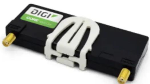 Note This is required only if you want to connect to a cellular network. A SIM card is also required. Note This is required only if you want to connect to a cellular network. A SIM card is also required. |
| SIM card | An activated SIM card provided by your cellular network operat You can insert up to two SIM cards in the CORE module. See Connect hardware and connect to a cellular network.The CORE module supports the standard mini-SIM cards (2FF).Note This is required only if you are using a CORE module to connect to a cellular network. |
| Antennas (2) | 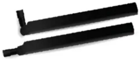 |
Optional equipment
| Equipment Description | |
| Power cord | IEC 60320 power cord.An additional power cord used for redundancy. |
Cellular ONLY: Insert the CORE module
Note If you are connecting to a network using an Ethernet connection, you can skip this section. See Connect hardware and connect to site network using an Ethernet LAN.
This section explains how to connect the CORE module and cellular antennas to the Connect IT hardware.
Prerequisites
■ Activated SIM card from your cellular network provider.
■ CORE module. This may be included with your device. If it is not, you must purchase one separately.
To connect the hardware and connect to the cellular network:
- Insert your activated SIM card into the CORE module. The notched end of SIM card should be inserted first, with the gold metal contacts facing down. You will hear a click once the SIM is completely inserted.
Note If one SIM card is being used, insert the SIM card into the SIM 1 slot.
- Insert the CORE module into the device.
a. Orient the device so the rear of the device is facing you.
b. Remove the CORE module slot cover from the back of the device.
c. Insert the CORE module into the slot. Make sure the pin holes on the back of the module match the location of the pins in the slot.
d. Push the module into the slot.
e. Push the white handle down until you hear it click.
f. Optionally, you can screw one of the CORE module cover screws into the center of the handle.
g. Place the white CORE module cover over the end of the device. Make sure that the antenna labels are oriented correctly.
h. Push the cover in place.
- Attach both of the included antennas. While gripping the metal connector section with your thumb and forefinger, tighten until secure. Do not tighten the antenna by holding any part of the plastic antenna housing.
Note Attaching both antennas ensures maximum performance. If a single antenna solution is required, it must be attached to the antenna port labeled MAIN.
Connect the power supplies and fans
You must purchase a power supply kit. Each kit includes three units: two fan and power supply units and one fan unit.
You can choose between the following two kits:
■ ITPS-PSEK: Connect IT 16/48 power supply kit, port-side exhaust. Use this when the serial ports will be in the hot aisle. The thumb screws used to connect the items to the Connect IT are blue.
■ ITPS-PSIK: Connect IT 16/48 power supply kit, port-side intake. Use this when the serial ports will be in the cold aisle. The thumb screws used to connect the items to the Connect IT are red.
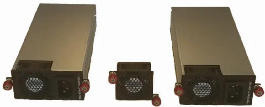
natural_image
Two industrial power supply units with cooling fans and red connectors, no visible text or symbols- Orient the device so the back of the device is facing you.
-
Connect the first power supply and fan unit to the Connect IT.
a. Orient a power supply and fan unit to match the picture shown above.
b. Insert the unit into the slot on the left side of the device.
c. Turn the red or blue screws to securely attach the unit to the device case. -
Connect the second power supply and fan unit to the Connect IT.
a. Orient the second power supply and fan unit to match the picture shown above.
b. Insert the unit into the slot on the right side of the device.
c. Turn the red or blue screws to securely attach the unit to the device case.
- Connect the stand-alone fan unit to the Connect IT.
a. Orient the fan unit to match the picture shown above.
b. Insert the fan into the slot next to the power supply and fan unit on the right side of the device.
c. Turn the red or blue screws to securely attach the fan to the device case.
Optional: Connect SFP+ modules
You can choose to connect up to two SFP+ modules to the Connect IT.
Note When you use an SFP+ module, you cannot use the equivalent Ethernet port. For example, if you insert an SFP+ module into the SFP+1 slot, you cannot use the ETH1 slot. If you insert an SFP+ module into the SFP+2 slot, you cannot use the ETH2 slot.
- Orient the device so the front of the device is facing you.
- Insert the first SFP+ module into the SFP+1 slot on the Connect IT.
- Insert the second SFP+ module into the SFP+2 slot on the Connect IT.
Connect the hardware
These sections explain how to connect the hardware and then connect to either a cellular network using the CORE module or to a site network using an Ethernet cable.
■ Connect hardware and connect to site network using an Ethernet LAN
■ Connect hardware and connect to a cellular network
Connect hardware and connect to site network using an Ethernet LAN
This section explains how to connect the Connect IT hardware and then connect to a site network, using an Ethernet WAN cable.
Prerequisites
■ CAT 5/6 Ethernet cable, which must be purchased separately.
To connect the hardware and connect to a site network:
- Connect the power supply and fan units to the device. See Connect the power supplies and fans.
- Plug the power supply unit into an AC power outlet and connect the other end to the Power plug on the 16/48.
-
Connect one end of an Ethernet cable to your site network.
-
Connect the other end of the Ethernet cable to the Ethernet ETH2 port on the 16/48. By default a DHCP request will be sent to the local Ethernet network.
Connect hardware and connect to a cellular network
This section explains how to connect the Connect IT hardware and then connect to a cellular network, using a CORE module. You must have purchased a CORE module to be able to connect to the cellular network.
Note As an alternative, you can also use an Ethernet LAN connection. See Connect hardware and connect to site network using an Ethernet LAN.
To connect the hardware and connect to the cellular network:
- Insert a CORE module with an activated SIM card. See Cellular ONLY: Insert the CORE module.
- Plug the power supply cord into at least one of the power supplies on the back of the device. The second power cord can also be plugged in, but it is not required. It is available for power redundancy.
- Plug the power supply unit into an AC power outlet to power up the Connect IT 16/48.
Connect equipment to the Connect IT serial ports
After your device is connected and powered up, you can connect equipment to the device using the serial ports.
The serial ports on the Connect IT provide console access to connected critical equipment through the cellular network or a connected Ethernet LAN. Depending on your model, you can connect up to 16 or 48 of your network devices to the Connect IT serial ports. For pinout information, see Serial connector pinout.
You must use a cable with an RJ45 connector to connect to the Connect IT 16/48 with a RJ45, DB9F or DB9M connector, as determined by your device type, to terminate to your device. Consult the user guide for the device you are connecting to the Connect IT to determine the connector type, cable type, and pinout positions for your specific device.
The serial ports are enabled by default. The network devices connected to the serial ports may be accessed using Remote Manager, the local web user interface, TCP, telnet, or SSH connections. TCP, telnet and SSH connections to serial ports are disabled by default and must be enabled by a device-specific configuration.
Serial connector pinout
The Connect IT console port is DTE. The Connect IT serial ports 1-48 (1-16 for IT 16) are DTE ports by default but may be software configured for DCE.
| Signal name Console port and DTE mode DCE mode | ||
| CTS 1 | N/ASignals are not used in DCE mode. | |
| DSR 2 | N/ASignals are not used in DCE mode. | |
| RXD 3 | 6 | |
| GND | 4 | 5 |
| GND/DCD | 5 | 4 |
| TXD 6 | 3 | |
| DTR | 7 | N/ASignals are not used in DCE mode. |
| RTS 8 | N/ASignals are not used in DCE mode. | |
Configure the Connect IT 16/48
You can configure the Connect IT 16/48 in either web UI method: the local web user interface or Remote Manager. Once you have selected a web UI option and logged in, the features and page layout are the same in both the local web user interface and Remote Manager.
Change a Connect IT password 16
Manage users and groups 16....
Update the firmware on the Connect IT 18
Configure authentication methods.19....
Configure idle timeout 20
Update modem firmware from the local web user interface 20....
Configure Remote Power Management.21
Configure a serial port 25.
Configure a modem 31
Configure the network 37
Configure the Connect IT name from the local web user interface 38
Configure a VPN 39
Back up, restore, and delete the configuration 40
Configure the firewall....41
Configure services 42
Monitor the data from the Connect IT.... 43
Reboot the Connect IT 43
Schedule system maintenance 45
Synchronize system time.... 46
View Connect IT status information 47
Download an archive of the supported MIBs 47
Download a support report file 47
Configure and view events and logs 48
Change a Connect IT password
You can change either the root password or the user password for the Connect IT.
- Log in to manage the Connect IT.
- Access the Configuration > Authentication screen.
- Expand the Users section.
- Determine for whom you want to change the password.
■ Expand the root section to change the root password for the Connect IT. -
Expand a section with a user name to change the password that user would use when logging on to the Connect IT.
-
In the Password field, enter a new password.
-
Select the Show option if you want the password to display in the field. If you don't select this option, a series of dots displays.
-
Click Save or Apply.
Manage users and groups
Users and groups work together to enable access to the desired serial ports and other features. Groups are assigned to user profiles and the users in the group inherit the access rights specified for that group.
Create a group
You can create a group that represents a set of users that should have the same access rights. After a group has been created, you should configure it to allow access to the desired serial ports and features. Users inherit the rights specified for that group.
- Log in to manage the Connect IT.
- Access the Configuration > Authentication screen.
- Expand the Groups section.
- Click Add or +.
- In the Add Group field, enter the group name.
- Click Add or OK. The new group is immediately added to the list of groups.
- Click Save or Apply.
- Configure an access control group.
Configure an access control group
You can configure an access control group to allow access to the desired serial ports and features.
Note The users to which this group is assigned inherit the access rights configured for the group. For information about assigning a group to a user, see Create a user profile and assign an access control group.
- Log in to manage the Connect IT.
- Access the Configuration > Authentication screen.
- Expand the Groups section.
- Expand the group that you want to configure: admin, serial, or a user group that you have added.
- Configure the group as desired.
| Setting Description | |
| Admin access When selected, members assigned to this group have full access to configure all of the features on the Connect IT. One admin group is available by default. | |
| Shell access When selected, members of this group can access a Linus shell on this Connect IT. | |
| Serial access When selected, members of this group have access to the set of ports listed in the Serial ports section. One serial group is available by default. | |
| Serial ports A list of ports to which members of this group may access.The Serial access option must be selected for the users in this group to have access to the ports.Click Add or+. A new port row is added.From the Port list box, select the appropriate port. | |
| OpenVPN access | When selected, allows members of this group access the specified OpenVPN tunnels listed in thOpenVPN section. |
| OpenVPN | A list of OpenVPN tunnels to which members of this group may access.The OpenVPN access option must be selected for the users in this group to have access to the tunnels. You must have previously added at least on OpenVPN tunnel.Click Add or+. A new tunnel row is added.From the Tunnel list box, select the appropriate tunnel. |
| Nagios access | When selected, allows members of this group to query the device for service status for Nagios. |
| Power outlet access | When selected, allows members of this group to access the power outlet specified in the Power outletssection. SeeCreate an access control group for power management and assign to users |
| Power outlets | Defines the outlets that members in this group can access. See create an access control group for power management and assign to users |
- Click Save or Apply.
Create a user profile and assign an access control group
You can create a new user profile and assign a log in password.
- Log in to manage the Connect IT.
- Access the Configuration > Authentication screen.
- Expand the Users section.
- Click Add or + to add a new user name.
- Select Enable. If the user profile is not enabled, the user will not be able to log in.
- Enter the password for this user in the Password field.
If the Show option is selected, the password appears in the field. If it is not selected, a series of dots appear.
- Assign the user to a group.
a. Expand the Groups section.
b. Click Add or +.
c. From the Group list box, select the desired group.
- Click Save or Apply.
Configure two-factor authentication for a user
You can configure two-factor authentication for a user.
- Log in to manage the Connect IT.
- Access the Configuration > Authentication screen.
- Expand the Users section.
- Expand the group that you want to configure for two-factor authentication.
- Expand the Two-factor authentication section.
- Click Enable.
- Complete the fields in the section.
- Click Save or Apply.
Update the firmware on the Connect IT
You can update the firmware on the Connect IT from either Remote Manger or the local web user interface.
Update Connect IT firmware from the local web user interface
You can update the firmware on the Connect IT. Before you begin, you must download the desired version of the firmware onto your PC.
- Download the Connect IT firmware to your PC.
- Log in to the Connect IT local web user interface.
- Select the System tab in the left pane.
-
In the Device Firmware section, click Choose File.
-
Browse for and select the firmware file downloaded to your PC.
- Click Update Firmware.
Update the firmware on Connect IT from Remote Manager
You can update the firmware on Connect IT from Remote Manager. You must first get the current firmware file, and then you can upload it to the device.
- Log in to your Remote Manager account.
- Click Try Remote Manager 3.0 preview in the top right of the screen.
- Click Devices in the left pane.
- Select the device you want to update.
- In the toolbar, click Actions > Update Firmware. The Update Firmware pane displays.
- From the list box, select the appropriate firmware option.
■ The most current firmware file.
- Upload Firmware File: Select this option if you want to use a firmware file other than the most current file. If you choose this option, you should Download the Connect IT firmware to your PC.
- Click Update to immediately update the firmware.
Download the Connect IT firmware to your PC
- Go to www.digi.com/support.
- Scroll down to the Support Downloads section.
- Click Firmware Updates.
- In the Filter the list box, enter Connect IT. As you type, matches display.
- Click Connect IT.
- From the list of options, select the option for your model: Connect IT 16 or Connect IT 48.
- From the Firmware Updates section, select the version you want to download. The file is downloaded to a folder on your computer. Make a note of the folder path and name.
Configure authentication methods
You can configure a list of the authentication methods to use when authenticating access to services on the Connect IT. The methods are attempted in the list order until the first successful authentication result is returned. A user fails authentication when no method succeeds.
- Log in to manage the Connect IT.
- Access the Configuration > Authentication screen.
-
Expand the Methods section. One method is included by default. The Local users option is selected by default.
-
You can add additional methods.
a. Click Add or +. The new row is immediately added to the list of methods.
b. From the Method list box, select the method that you want to use for authentication:
■ Local users: Authenticate using the users defined with the configuration.
■ TACACS+: Authenticate using an external TACACS+ server. If you choose this option, make sure you have configured an external TACACS+ server, in Step 5.
- Configure an external TACACS+ server. This allows access to services on this Connect IT to be authenticated externally, which is useful for central management of users.
Note This step is required only if you chose the TACACS+ option in Step 4.
Expand each sub-section and complete the fields in each of the sections. To display information about what you should enter in each field, click the down arrow and then Help next to each field.
- Click Save or Apply.
Configure idle timeout
You can configure the length of time after which users are disconnected from services. If you do not enter a value, the idle timeouts feature is disabled, and the user will not be disconnected from services.
- Log in to manage the Connect IT.
- Access the Configuration > Authentication screen.
- In the Idle timeout field, enter the length of time after which users are disconnected from services. Leave this field blank to disable this feature.
Syntax: number{w|d|h|m|s} - Click Save or Apply.
Update modem firmware from the local web user interface
You can update the modem firmware on the Connect IT. Before you begin, you must download the desired version of the modem firmware onto your PC.
- Download the Connect IT firmware to your PC.
- Log in to the Connect IT local web user interface.
- Select the System tab in the left pane.
- Scroll down to the Modem Firmware section.
- Click Choose File.
- Browse for and select the modem firmware file downloaded to your PC.
- Click Upload & Install Firmware.
Configure Remote Power Management
The remote power management feature allows you control outlets on a power controller using serial or network interfaces. As you manage a device which is connected to a serial port on the Connect IT, you can also control the power outlets you have associated with that serial port.
Follow this process to configure a power controller and an access control group for power management:
- Configure the Connect IT to connect to a power controller
- Create an access control group for power management and assign to users
You can control power from the local web UI or from a terminal console. Power control consists of three basic functions: on, off, and power cycle.
■ View power controller status and manage power (Administrators)
■ Control the outlet power from a terminal (all users)
Configure the Connect IT to connect to a power controller
You can configure the Connect IT to connect to the power controller. During this process, you must decide which method you want to use to make the connection: serial or TCP.
■ Serial Connection
To use a serial port, you must configure a serial port on the Connect IT to communicate with a power controller. You can then connect the power controller to the serial port on the Connect IT using a serial cable.
- Review the serial settings for your power controller. You will use this information to configure the Connect IT.
- Verify that your serial cable has the correct pinout. See Serial connector pinout.
- Configure a serial port for Power Management
- Connect a power controller to the Connect IT serial port.
- Configure communication with a power controller. Choose Serial as the connection type.
■ Network Connection
Configure communication with a power controller. Choose TCP as the connection type.
Configure a serial port for Power Management
You can configure a serial port on the Connect IT to communicate with the power controller.
- Log in to manage the Connect IT.
- Access the Configuration > Serial screen.
- Expand the port that you want to configure for use with the power controller.
- Select Enable.
- From the Serial mode list box, select the Power management option.
-
In the Label field, enter a descriptive name for the port.
-
The entries in the following fields must match the information for the power controller. Refer to your power controller manual for the correct entries: Baud rate, Data bits, Parity, Stop bits, and Flow control.
- Click Save or Apply.
Connect a power controller to the Connect IT serial port
After you have configured a serial port on the Connect IT and configured the power controller, you should connect the Connect IT and the power controller with a serial cable.
- Connect one end of a serial cable to the power controller.
- Connect the other end of the serial cable to the Connect IT. Make sure you connect the serial cable to the serial port you previously configured. See Configure a serial port for Power Management.
Configure communication with a power controller
You can configure the Connect IT to communicate with a power controller.
- Log in to manage the Connect IT.
- Access the Configuration > Remote Power Management screen.
- In the Controller monitor interval field, specify the number of seconds to wait between power controller status checks.
- Select Enable.
- Click Controllers.
- Configure a name for a power controller. In the Add Power controller field, enter a name for the power controller, and then click Add.
- From the Controller type list box, the appropriate controller type.
- Specify the connection type from the Connection type list box: Serial or TCP.
Serial
a. Select Serial port from the Connection type list box. The Serial port field appears.
b. In the Serial port field, select the port number from the list box. You should select the same serial port number previously configured. See Configure a serial port for Power Management.
TCP
a. Select TCP from the Connection type list box. Additional fields appear.
b. In the Network hostname field, enter the name or IP address of the network host.
c. In the TCP port field, enter the port number that will be used for the connection.
- Configure the outlets on the power controller that can be controlled by the port.
a. Click Outlets to expand the outlet section.
b. Define an outlet on the power controller. In the Add Outlet field, enter a name for the outlet and then click Add.
c. In the Outlet index field, enter the appropriate outlet index. Refer to the manual for your power controller to determine the outlet index.
d. Repeat the process to configure additional outlets.
- Click Save or Apply.
Create an access control group for power management and assign to users
You can create an access control group that enables users to control a power outlet from inside a terminal session. For each access control group, you can configure a serial port and the associated outlets, and then assign the group to users that are allowed access to the outlets on that port.
Note For information about accessing and using a terminal session, see Control the outlet power from a terminal (all users).
- Log in to manage the Connect IT.
- Access the Configuration > Authentication screen.
- Expand the Groups section.
- Add a group.
- Select the Serial access option.
-
Configure the serial port for the group.
a. Expand the Serial ports section.
b. Click Add or +.
c. From the Port list box, select a port for the group. The port should have been previously configured. See Configure a serial port for Power Management. -
Select the Power outlet access option.
-
Configure the power outlets for the group.
a. Expand the Power outlets section.
b. Select the Power outlet access option.
c. Click Add or +.
d. From the Outlet list box, select an outlet for the group.
e. Repeat the process to add additional outlets.
-
Assign the power management group to the users that should have access to the ports in the group. See Create a user profile and assign an access control group.
-
Click Save or Apply.
View power controller status and manage power (Administrators)
You can view the status of each outlet configured for a power controller and turn the power to an outlet on and off.
Note This process can only be done in the local web UI. Only admin users can access the Power Controllers page. Non-administrators can control the power in a Terminal screen. See Control the outlet power from a terminal (all users).
- Log in to the Connect IT local web user interface.
- Click Status in the left pane.
- Expand the Power section. The Power Controllers page appears.
- You can do the following:
View power controller status
Each outlet and power controller combination configured for remote power management appears in the page. The state of the power for each outlet is displayed:
■ on: The outlet has power.
■ off: The outlet does not have power.
■ unknown: The Connect IT 16/48 cannot get a status from the power controller.
Change the power state
You can change the power state for an outlet.
a. From the Change State list box, select an option from the list box.
■ On: Turn on the power to that outlet.
■ Off: Turn off the power to that outlet.
■ Cycle: Turn the power off, then on. If the power state for the outlet is currently off, then the power is just turned on.
b. Click Apply.
View power manager log
A log of all remote power management events appears in the Power Manager Log. Click Download to download a copy of the log.
Control the outlet power from a terminal (all users)
A user can log into a terminal on the Connect IT and then power the device connected to an outlet on and off.
- Log in to manage the Connect IT.
- Access the Terminal screen.
-
When prompted, enter your user name and password.
-
Information about the port you are connected to, as well as commands.
Connecting to port3: PowerManPort3
Settings: 9600, 8, 1, none, none
Type '~.' to disconnect from port
Type '~?' to list commands
- Enter \~? to display additional commands.
| Command Description | |
| ~. Disconnect from the port. | |
| ~B Send a BREAK sequence. | |
| ~c Clear the history buffer. | |
| ~r Send a DTR reset sequence. | |
| ~P Cycle the outlets on this port. | |
| ~O Power off all the outlets on this port. | |
| ~N Power on all the outlets on this port. | |
| ~? | Display a list of commands. |
- Enter \~. to disconnect from the port.
Configure a serial port
You can configure the connection, determine if changes are monitored, and enable a TCP, Telnet, or SSH connection for each serial port. Each port must be individually configured.
Configure the connection settings for a serial port
You can configure the serial ports on the Connect IT. Each port must be configured individually.
- Log in to manage the Connect IT.
- Access the Configuration > Serial screen.
- Expand the port that you want to configure.
- Configure the settings.
| Setting | Description |
| EnableSetting Description | Select the Enable option to enable this port for use. If it is not selected, the port won't work. |
| Serial mode Select an access mode for this serial port.■ Login: Select this option to display the Login Manger screen when you access the web UI.■ Remote access: Select this option to allow remote management. This is the default.■ Power management: Select this option to allow communication with a power controller. See Configure a serial port for Power Management. | |
| Label The name of the serial port. If left blank, the default label is used.An entry is optional. | |
| Baud rate The baud rate for the serial port. This value must match the baud rate configuration for the equipment connected to the Connect IT.The default is 9600. | |
| Data bits The number of data bits for the serial port. This value must match the data bits configuration for the equipment connected to the Connect IT.The default is 8. | |
| Parity The type of parity bit for the serial port. This value must match the parity bit configuration for the equipment connected to the Connect IT.The default selection is NONE. | |
| Stop bits The number of stop bits for the serial port. This value must match the stop bits configuration for the equipment connected to the Connect IT.The default is 1. | |
| Flow control | The type of flow control for the serial port. This value must match the flow control configuration for the equipment connected to the Connect IT.The default selection is NONE. |
| Escape sequence The sequence of | characters used to start an escape sequence. Escape sequences allow a user to send control commands t the serial port interface. These commands are removed from the data stream and are not sent to the equipment connec to the serial port. If left blank, the escape sequence is disabled. The default is a tilde (~). An entry is optional. |
| Note This option is available only when Remote Access is selected from the Serial mode list box. | |
| History size The number of bytes | from the serial port which should be buffered. The buffered bytes are redisplayed when a user connects to the serial port. The minimum value is 0. The default is 4000. |
| Note This option is available only when Remote Access is selected from the Serial mode list box. | |
| Exclusive access Select this option | if access to the serial port should be limited to a single active section. If not selected, multiple active sessions are available on the port. |
| Note This option is available only when Remote Access is selected from the Serial mode list box. | |
| Idle timeout The length of time after which the active session is disconnected after a period of user inactivity. Syntax: number{w|d|h|m|s} A setting of 0 disables idle timeouts. The default is 15m. | Note This option is available only when Remote Access is selected from the Serial mode list box. |
- Click Save or Apply.
Monitor serial port changes
You can choose to monitor CTS and/or DCD changes on the serial port.
- Log in to manage the Connect IT.
- Access the Configuration > Serial screen.
- Expand the port that you want to configure.
- Expand the Monitor section.
- Configure the settings.
| Setting Description | |
| CTS Select the CTS option to monitor CTS changes on this port. | |
| DCD Select the DCD option to monitor DCD changes on this port. | |
- Click Save or Apply.
Enable a Telnet connection on the serial port
You can enable a Telnet connection on the serial port.
- Log in to manage the Connect IT.
- Access the Configuration > Serial screen.
- Expand the port that you want to configure.
- Expand the Telnet connection section.
- Configure the settings.
| Setting Description | |
| Enable | Select the Enable option to allow the serial port to be directly accessed by a Telnet connection. |
WARNING! This connection is not authenticated or encrypted. | |
| Port | Specify the Telnet port for the service.Minimum value: 1Maximum value: 65535Default: 2001 |
- Specify the addresses, interfaces, and firewall zones which are allowed to access the serial port. Expand the Access control list.
| Setting Description | |
| IPv4 Addresses | Expand the IPv4 Addresses section to add IPv4 addresses or networks from which this serial port can be accessed. Click Add to add an address. |
| IPv6 Addresses | Expand the IPv6 Addresses section to add IPv6 addresses or networks from which this serial port can be accessed. Click Add to add an address. |
| Interfaces | Expand the Interfaces section to add network interfaces from which this serial port can be accessed. Click Add to add an interface. |
| Zones | Expand the Zones section to add firewall zones from which this serial port can be accessed. Click Add to add a zone. |
- Click Save or Apply.
Enable a TCP connection on the serial port
You can enable a TCP connection on the serial port.
- Log in to manage the Connect IT.
- Access the Configuration > Serial screen.
- Expand the port that you want to configure.
- Expand the TCP connection section.
- Configure the settings.
| Setting Description | |
| Enable | Select the Enable option to allow the serial port to be directly accessed by a raw TCP connection. |
WARNING! This connection is not authenticated or encrypted. | |
| Port | Specify the TCP port for the service.Minimum value: 1Maximum value: 65535Default: 4001 |
- Specify the addresses, interfaces, and firewall zones which are allowed to access the serial port. Expand the Access control list.
| Setting Description | |
| IPv4 Addresses | Expand the IPv4 Addresses section to add IPv4 addresses or networks from which this serial port can be accessed. Click Add to add an address. |
| IPv6 Addresses | Expand the IPv6 Addresses section to add IPv6 addresses or networks from which this serial port can be accessed. Click Add to add an address. |
| Interfaces | Expand the Interfaces section to add network interfaces from which this serial port can be accessed. Click Add to add an interface. |
| Zones | Expand the Zones section to add firewall zones from which this serial port can be accessed. Click Add to add a zone. |
- Click Save or Apply.
Enable an SSH connection on the serial port
You can enable an SSH connection on the serial port.
- Log in to manage the Connect IT.
- Access the Configuration > Serial screen.
- Expand the port that you want to configure.
- Expand the SSH connection section.
- Configure the settings.
| Setting Description | |
| Enable | Select the Enable option to allow the serial port to be directly accessed by anSSH connection. |
| Port | Specify the SSH port for the service.Minimum value: 1Maximum value: 65535Default: 3001 |
- Specify the addresses, interfaces, and firewall zones which are allowed to access the serial port. Expand the Access control list.
| Setting Description | |
| IPv4 Addresses | Expand the IPv4 Addresses section to add IPv4 addresses or networks from which this serial port can be accessed. Click Add to add an address. |
| IPv6 Addresses | Expand the IPv6 Addresses section to add IPv6 addresses or networks from which this serial port can be accessed. Click Add to add an address. |
| Interfaces | Expand the Interfaces section to add network interfaces from which this serial port can be accessed. Click Add to add an interface. |
| Zones | Expand the Zones section to add firewall zones from which this serial port can be accessed. Click Add to add a zone. |
7. Click Save or Apply.
Configure a modem
You can enable a modem in the Connect IT and configure the modem to enable gateways and network interfaces.
Configure the modem
You can configure the modem in the Connect IT.
- Log in to manage the Connect IT.
- Access the modem settings.
■ local web UI: Click Configuration in the left pane and then expand the Modem section.
■ Remote Manager: Click Config > Network and then expand the Modem section.
- Configure the settings.
| Setting Description | |
| Enable Select Enable to enable the | network interface. |
| Interface type The address configuration | method for the network interface.■ Modem: The address is determined by the cellular modem.The default is Modem. |
| Zone | The firewall zone assigned to this network interface. This be used by packet filtering rules and access control lists to restrict network traffic on this interface.The default is External. |
| Device | The modem used by this network interface.The default is Modem. |
| Match SIM by The match criteria to apply when determining if this interface should be used.■ Any SIM: Apply this interface to the modem with any SIM.■ SIM slot: Apply this interface when a specified SIM slot is active. An entry in the Match SIM slot field is required.■ Carrier: Apply this interface with SIM cards from a particular cellular carrier. An entry in the Match SIM carrier field is required.■ PLMN identifier: Apply this interface with SIM cards that have a specific PLMN identifier. An entry in the Match PLMN identifier field is required.■ IMSI: Apply this interface with SIM cards that have a specific IMSI. An entry in the Match IMSI field is required.■ ICCID: Apply this interface with SIM cards that have a specific ICCID. An entry in the Match ICCID field is required. | |
| Match SIM slot | This conditional field displays when the SIM slot option is selected from the Match SIM by list box.Enter the SIM slot match criteria. The interface is applied when the modem is using this SIM slot. Modems with a single SIM slot will always match SIM1.The default value is SIM1. |
| Match SIM carrier | This conditional field displays when the Carrier option is selected from the Match SIM by list box.Select the appropriate SIM carrier from the list box. The interface is applied when the SIM card is provisioned from the carrier.The default value is AT&T. |
| Match PLMN identifier | This conditional field displays when the PLMN identifier option is selected from the Match SIM by list box.Enter the SIM PLMN (Public Land Mobile Network) match criteria. The interface is applied when the SIM card is provisioned from the carrier with this PLMN carrier. The PLMN identifier consists of the Mobile Country Code (MCC) followed by the Mobile Network Code (MNC). |
| Match IMSI | This conditional field displays when the IMSI option is selected from the Match SIM by list box.Enter the IMSI (International Mobile Subscriber Identity) match criteria. The interface is applied when the SIM card has this IMSI. |
| Match ICCID This conditional field displays when the ICCID option is selected from the Match SIM by list box.Enter the ICCID (Integrated Circuit Card Identifier) match criteria. The interface is applied when the SIM card has this ICCID. | |
| PIN | The PIN required to unlock the SIM card. Leave blank if not PIN is required. |
| Phone Number The phone number | stored on the SIM card will be automatically reported to enable SMS services. If the SIM is not provisioned with a phone number, or it contains an incorrect phone number, it will be necessary to complete this field with the correct phone number to reach this device. In normal operation, this field should be blank. |
| Roaming | Enable roaming to allow connections to data services outside of the original country of the SIM. When enabled, the cost of data use may increase significantly. |
| Use DNS Specify when this interface's DNS servers will be used.Always: Always use the DNS servers provided for this interface. If multiple interfaces have the same DNS server, requests to the DNS server will be routed through the interface with the lowest metric.When primary default route: Use the DNS servers provided for this interface only when the interface is the primary default route. This is the default.Never: Never use the DNS servers provided for this interface. | |
| SIM failover | Enable SIM failover to automatically switch the active SIM slot to the next available SIM if the modem interface fails to connect. |
| Connection attempts before SIM failover | The number of unsuccessful connection attempts before switching to the next SIM slot.Minimum value: 1The default value is 5. |
| SIM failover alternative The action | to perform when the connection retries have been exceeded but no other SIM is available to switch to.■ None: Perform no alternative action.■ Reset modem: Reset the modem if the SIM failover feature is not enabled and thus automatic SIM switching is not available.■ Reboot device: Reboot the device if the SIM failover feature is not enabled and thus automatic SIM switching is not available. |
| APN list only Determine which APN | should be used.■ Enabled: When enabled, the APN list is used exclusively. For more information, see Define a custom APN list.■ Disabled: When disabled, configured APNs are tried before the APNs built into the firmware are tried. |
| APN list Define a list of custom APNs to try when connecting to the cellular network. See Define a custom APN list. | |
| Custom gateway Configure a custom gateway/netmask that overrides the automatic values normally provided. This is particularly useful when supporting a group of static UP addresses that communicate directly. See Configure a custom gateway for the modem. | |
| IPv4 | Configure an IPv4 network interface. See Configure an IPv4 network interface for the modem. |
| IPv6 | Configure an IPv6 network interface. See Configure an IPv6 network interface for the modem. |
4. Click Save or Apply.
Define a custom APN list
You can define a list of custom APNs to try when connecting to the cellular network.
- Log in to manage the Connect IT.
- Access the Modem section.
- Expand the APN list section.
- Enable the APN list only option.
- Click Add or +.
-
In the APN field, enter the APN name used when connecting to the network.
-
From the APN version list box, select the IP version for which the modem may request addresses.
- From the Authentication method list box, select the authentication method used to connect to the cellular network. Authentication is attempted only if a user name has been set.
- Click Save or Apply.
Configure a custom gateway for the modem
You can configure a custom gateway/netmask that overrides the automatic values normally provided. This is particularly useful when supporting a group of static UP addresses that communicate directly.
- Log in to manage the Connect IT.
- Access the Modem section.
- Expand the Custom gateway section.
- Configure the settings.
| Setting Description | |
| Enable Select Enable to enable a custom gateway for this network interface. | |
| Gateway/Netmask The gateway address and netmask to use for this network interface. If either the gateway address or the netmaks is all 0's, it is not overridden. For example, 0.0.0.0/32 will operate as normal using the network-provided gateway IP, but with a /32 netmask. | |
- Click Save or Apply.
Configure an IPv4 network interface for the modem
You can configure an IPv4 network interface.
- Log in to manage the Connect IT.
- Access the Modem section.
- Expand the IPv4 section.
- Configure the settings.
| Setting Description | |
| Enable Select Enable to enable an IPv4 network interface. | |
| Metric The priority of routes associated with the network interface. If there are multiple active routes that match a destination, then the route with the lowest metric will be used.Default: 3Minimum: 0Maximum: 65535 | |
| Weight The relative weight of default routes associated with this network interface. If there are multiple active default routes with the same metric, then connections will be load-balanced between the default routes in proportion to their weight.Default: 10Minimum: 1Maximum: 65535 | |
| Management priority The management priority assigned to this interface.An interface that is up and has the highest management priority will have its address reported as the preferred contact address for central management and direct device access.Default: 0Minimum: 0Maximum: 1000 | |
| MTU Specify a desirable Maximum Transmission Unit(MTU) for this interface. If this is a non-static (DHCP) interface, the lower MTU value of the one offered by the DHCP and the one specified will be in effect.Default: 1500Minimum: 576Maximum: 65535 | |
| Active recovery | Active recovery performs regular network tests to determine if working connections can be made to remote targets. The network tests available are ping tests, HTTP/HTTPS tests, and DNS tests. This interface's default route will be disabled when the connectivity tests fail, allowing other interfaces with lower metrics to take precedence. |
- Click Save or Apply.
Configure an IPv6 network interface for the modem
You can configure an IPv6 network interface.
- Log in to manage the Connect IT.
- Access the Modem section.
- Expand the IPv6 section.
- Configure the settings.
| Setting Description | |
| Enable Select Enable to enable an IPv4 network interface. | |
| Metric The priority of routes associated with the network interface. If there are multiple active routes that match a destination, then the route with the lowest metric will be used.Default: 3Minimum: 0Maximum: 65535 | |
| Weight The relative weight of default routes associated with this network interface. If there are multiple active default routes with the same metric, then connections will be load-balanced between the default routes in proportion to their weight.Default: 10Minimum: 1Maximum: 65535 | |
| Management priority The management priority assigned to this interface.An interface that is up and has the highest management priority will have its address reported as the preferred contact address for central management and direct device access.Default: 0Minimum: 0Maximum: 1000 | |
| MTU Specify a desirable Maximum Transmission Unit(MTU) for this interface. If this is a non-static (DHCP) interface, the lower MTU value of the one offered by the DHCP and the one specified will be in effect.Default: 1500Minimum: 576Maximum: 65535 | |
| Active recovery | Active recovery performs regular network tests to determine if working connections can be made to remote targets. The network tests available are ping tests, HTTP/HTTPS tests, and DNS tests. This interface's default route will be disabled when the connectivity tests fail, allowing other interfaces with lower metrics to take precedence. |
- Click Save or Apply.
Configure the network
You can configure the network for the Connect IT.
- Log in to manage the Connect IT.
-
Access the Configuration > Network screen.
-
Each sub-section enables you to configure a different network type. Expand the sub-section and complete the fields in each of the sections. To display information about what you should enter in each field, hover over the field name or click the down arrow and then Help next to each field.
| Section Description | |
| Interfaces | Configure the interface types that you want to use. |
| Virtual LAN | A list of virtual LAN devices supporting the IEEE 802.1Q standard. These are virtual devices that are layered over an Ethernet device by including a VLAN tag within the Ethernet frame. The VLAN tag contains the VLAN identifier associated with the virtual LAN. |
| Bridges | A list of bridges supporting that IEEE 802.1D standard. A bridge learns which addresses are associated with devices on the bridge, and automatically forwards packets between devices as required. Bridged packets bypass the firewall. |
| Routes | Configure a list of the routing methods you want to use. |
| Modems | Settings for cellular modems. Each modem configuration describes the modem it applies to, and the settings for the modem. |
| Dynamic DNS | Dynamic DNS allows the IP address of a network interface to be registered with an external dynamic SNS service provider. This is useful when external systems need to initiate connections to this device, but the IP address assigned to the interface is not static. |
| VRRP | A list of VRRP (Virtual Router Redundancy Protocol) instances. |
| Advanced | Configure the ULA prefix for this site, and the TCP read and write buffer window size. |
- Click Save or Apply.
Configure the Connect IT name from the local web user interface
You can configure a descriptive name for the Connect IT, which displays in prompts and log messages. You can also configure additional descriptions for the Connect IT.
- Log in to the Connect IT local web user interface
- Click Configuration in the left pane.
- Expand the System section.
- Enter values into the fields.
| Field Description | |
| Name | The name for the Connect IT. This name displays in prompts and log messages. |
| Contact | Contact information for this Connect IT. This is for reference only. |
| Location | A description of the Connect IT's physical location. This is for reference only. |
| Description | A description of the Connect IT. This is for reference only. |
| Banner | A banner message that displays when a user accesses terminal services on this device. This is for reference only. |
- Click Save at the bottom of the screen to save the changes.
Configure a VPN
Configure an IPsec tunnel for a VPN
You can configure an IPsec tunnel for a VPN.
- Log in to manage the Connect IT.
- Access the Configuration > VPN screen.
-
Expand the IPsec section.
-
Set the NAT keep alive time.
a. Expand the advanced section.
b. In the NAT keep alive time field, enter the length of time to keep NAT alive for IPSEC tunnels. the default is 40 seconds. The syntax for the entry is number {w|d|h|m|s}.
- Create an IPsec tunnel.
a. Expand the Tunnels section.
b. In the Add IPsec tunnel field, enter a name for the tunnel.
c. Click Add.
d. The tunnel is enabled by default. Verify that the Enable option is selected.
e. Complete the fields in each of the sections. To display information about what you should enter in each field, hover over the field name or click the down arrow and then Help next to each field.
- Click Save or Apply.
Configure an OpenVPN server
You can configure an OpenVPN server and define clients. To display information about what you should enter in each field, hover over the field name or click the down arrow and then Help next to each field.
- Log in to manage the Connect IT.
- Access the Configuration > VPN screen.
- Expand the OpenVPN section.
-
Define an OpenVPN server.
a. Expand the OpenVPN section.
b. Expand the Servers section.
c. In the Add OpenVPN server field, enter a name for the server.
d. Click Add.
e. The server is enabled by default. Verify that the Enable option is selected.
f. Complete the fields in each of the sections. -
Define a client.
a. Expand the Clients section.
b. In the Add OpenVPN client field, enter a name for the client.
c. Click Add.
d. Verify that the Enable option is selected.
e. Verify that the Use .ovpn file option is selected.
f. Complete the fields in each of the sections.
- Click Save or Apply.
Configure an IP tunnel for a VPN
You can configure an IP tunnel for a VPN.
- Log in to manage the Connect IT.
- Access the Configuration > VPN screen.
- Expand the IP Tunnels section.
- In the Add IP tunnel field, enter a name for the tunnel.
- Click Add.
-
Click Save or Apply.
-
The tunnel is enabled by default. Verify that the Enable option is selected.
-
Complete the fields in each of the sections. To display information about what you should enter in each field, hover over the field name or click the down arrow and then Help next to each field.
Back up, restore, and delete the configuration
You can back up, restore, or delete configuration settings for a Connect IT.
Back up the Connect IT configuration
From the System page in the local web user interface, you can back up the Connect IT configuration file and save it to your PC. You can then use that file to restore the saved configuration to any Connect IT.
- Log in to the Connect IT local web user interface.
- Click System in the left pane.
- Scroll to the Configuration Management section.
- In the Passphrase field, enter a password for the configuration file you are going to save. This is used when you restore the configuration file.
- Click Save Config. The file is created and saved in the download folder on your PC.
Restore the Connect IT configuration
From the System page in the local web user interface, you can restore a Connect IT configuration file that was previously backed up.
This feature is useful if you want to copy the configuration from one Connect IT to others.
- Log in to the Connect IT local web user interface.
- Click System in the left pane.
- Scroll to the Configuration Management section.
- In the Passphrase field, enter the password for the configuration file that you want to restore.
- Click Choose File to select a configuration file that was previously backed up.
- Browse for and select the file. The file name appears in the page.
- Click Restore Config to copy the configuration from the file to the Connect IT.
Delete the Connect IT configuration
From the System page in the local web user interface, you can remove the Connect IT configuration.
- Log in to the Connect IT local web user interface.
- Click System in the left pane.
- Scroll to the Configuration Management section.
- Click Erase Config to remove the configuration from the Connect IT.
Configure the firewall
You can configure the firewall for the Connect IT.
- Log in to manage the Connect IT.
- Access the Configuration > Firewall screen.
- Each sub-section enables you to configure a firewall component. Expand the sub-section and complete the fields in each of the sections. To display information about what you should enter in each field, hover over the field name or click the down arrow and then Help next to each field.
| Section Description | |
| Zones | Configure the groups of network interfaces that can be referred to by packet filtering rules and access control lists. |
| Port forwarding | Configure a list of port forwarding rules. These rules allow network connections to the Connect ITto be forwarded to other servers by translating the destination address. |
| Packet filtering | Configure a list of packet filtering rules. These rules define whether to accept or reject network connections that are forwarded through the Connect IT. |
| Custom rules | Configure a script that is run to install advanced firewall rules beyond the scope or capabilities of the standard Connect IT configuration. |
| Quality of Service | Configure the quality of service, bandwidth allocation, traffic shaping, and traffic prioritizing features. |
- Click Save or Apply.
Configure services
You can configure services for the Connect IT.
- Log in to manage the Connect IT.
- Access the Configuration > Services screen.
- Each sub-section enables you to configure a different service. Expand the sub-section and complete the fields in each of the sections. To display information about what you should enter in each field, hover over the field name or click the down arrow and then Help next to each field.
| Section Description | |
| Web administration | The web administration service provides an HTTPS interface for managing the Connect IT. |
| SSH | The SSH service provides and SSH server for managing the Connect IT. |
| Telnet The Telnet service provides a Telnet server for managing the Connect IT.Note Telnet is an insecure protocol. It should only be used for compatibility reasons, and only if steps have been taken to ensure the network connection is secure. | |
| DNS The DNS service provides a caching server. This server forwards queries to the DNS servers that are associated with the network interfaces, and caches the results.Note This server is used within the Connect IT, and cannot be disabled. Use the access control list to restrict external access to this server. | |
| Remote control Not available. | |
| SNMP | The SNMP service provides an SNMP agent for using SNMP management on this Connect IT. |
| Multicast | The multicast service provides a multicast route. |
| Service Discover (mDNS) | Provide discovery services via multicast DNS. |
- Click Save or Apply.
Monitor the data from the Connect IT
You can configure the network for the Connect IT.
- Log in to manage the Connect IT.
- Access the Configuration > Monitoring screen.
- Each sub-section enables you to configure a different monitoring method. Expand the sub-section and complete the fields in each of the sections. To display information about what you should enter in each field, click the down arrow and then Help next to each field.
| Section Description | |
| NetFlow probe | Probe network traffic on this device and export statistic to NetFlow collectors. |
| Device Health | Device Health is a system monitor that collects and sto metrics over a period to time and reports them to Digi Remote Manager. |
| intelliFlow Reserved for future use. |
- Click Save or Apply.
Reboot the Connect IT
You can choose to reboot the Connect IT from the local web user interface or from Remote Manager.
Immediately reboot the Connect IT from the local web user interface
You can reboot the Connect IT from the local web user interface. The device is immediately restarted.
Note You can also choose to schedule a daily reboot. See Schedule a reboot from the local web user interface.
- Log in to the Connect IT local web user interface.
- Click System in the left pane.
- In the Device Reboot section, click Reboot.
Immediately reboot the Connect IT from Remote Manager
You can reboot the Connect IT from Remote Manager. The device is immediately restarted.
Note You can also choose to schedule a daily reboot. See Schedule a reboot from the local web user interface.
- In a web browser, type https://remotemanager.digi.com.
- Type your login credentials in the Username and Password fields.
- Click Log in.
- Click Try Remote Manager 3.0 preview in the top right of the screen.
- Click Devices in the left pane.
- Click on a device.
- In the toolbar, click Actions > Reboot.
Schedule a reboot from the local web user interface
You can schedule the Connect IT to automatically reboot every day at a scheduled time.
Note You can also choose to reboot the Connect IT immediately. See Immediately reboot the Connect IT from the local web user interface.
- Log in to the Connect IT local web user interface.
- Click Configuration in the left pane.
- Expand the System section.
- Expand the Scheduled tasks section.
- In the Reboot time field, enter the time at which the Connect IT should reboot every day. If the Connect IT is unable to synchronize its time with an NTP server, the Connect IT automatically reboots after 24 hours of uptime. The syntax for this field is: HH:MM
- Click Save at the bottom of the screen to save the changes.
Schedule system maintenance
You can schedule the system to run a set of system maintenance tasks to run within a specified time window. You can also schedule a custom script to run at the specified time and frequency.
Note If you are scheduling a custom script, you must have previously created the script.
For example, you can specify a start time of 10:00 and a duration window of 2 hours. In this example, the system maintenance can take place and custom scripts run at any time between 10:00 and 12:00.
- Log in to manage the Connect IT.
- Access the Configuration > System screen.
- Expand the System section.
- Expand the Scheduled tasks section.
- Expand the System maintenance section.
- Enter values into the fields.
| Field Description | |
| Start time The start time of the maintenance window. All enabled maintenance tasks take place at any random time within the time block specified in the Duration window field. If this field is empty, maintenance is not scheduled and no maintenance tasks will run. Syntax: HH:MMIf the duration in the Duration window field is set to 1 or more hours, the minutes field is truncated. | |
| Duration window The window of time during which the maintenance tasks are scheduled to run. The default values is 2 hours.■ 24 hours: If this option is selected, the start time entered in the Start Time field becomes obsolete, as a value of 24 hours means the maintenance tasks are scheduled to run at any time during a 24-hour time period.■ Immediately: If this option is selected, all maintenance processes will execute at the same time. This could potentially be dangerous, as this action may stress the system. | |
| Frequency The frequency at which the modem firmware check and update tasks will run. The default value isDaily.■Daily: The device runs the modem firmware check and update once a day within the given time window.■Weekly: The device runs the modem firmware check and update any day within the given time window only once during the week. | |
| Modem firmware update | Select this option to enable the modem firmware update to be scheduled to occur within the specified maintenance window. The system looks for all available firmware over the air and in flash memory to see if an update is needed. If a newer firmware version is available, the update will occur. |
| Configuration check Select this option | to enable the system to check if configuration updates are scheduled to occur within the specified maintenance window.This check is in addition to the check defined in theCentral Managementsection. |
- Configure a custom script to be run during the specified maintenance window.
a. Expand the Custom Scripts section.
b. Add a script name.
c. Verify that the Enable option is selected.
d. Complete the fields in each of the sections. To display information about what you should enter in each field, hover over the field or click the down arrow and then Help.
- Click Save or Apply.
Synchronize system time
You can define the Connect IT time zone and specify the servers that should be used to synchronize its time.
- Log in to manage the Connect IT.
- Access the Configuration > System screen.
- Expand the Time section.
-
In the Timezone field, enter the time zone for the Connect IT's physical location. The time zone is used to adjust the time for logged messages and to start scheduled system maintenance.
-
Specify the NTP servers used to synchronize the time on the Connect IT.
a. Expand the NTP servers section.
b. In the Server field, enter the name of the NTP server that is used to synchronize the time. The syntax is: {hostname|UPv4_address|IPv6_address}
c. If you want to enter an additional NTP server, click Add to add a new row and enter the NTP server name.
- Click Save or Apply.
View Connect IT status information
In the Status page in the local web user interface, you can view status information about the Connect IT, cellular modem, network connections, tunnels, and the equipment connected to the serial ports.
The Status page displays by default when you open the local web user interface.
- Log in to the Connect IT local web user interface.
- Click Status in the left pane.
- Click the desired tab to display status information.
■ Device Details: Displays status information about the Connect IT.
■ Cellular Details: Displays status information about the cellular modem, cellular network connection, and the SIM cards.
■ Networks: Displays status information about the network interfaces and network devices.
■ Tunnels: Displays status information about open tunnels.
■ Serial: Displays information about the status of the serial ports.
Download an archive of the supported MIBs
You can download a .zip archive of the MIBs supported by this device.
- Log in to the Connect IT local web user interface.
- Select the System tab in the left pane.
- Scroll down to the SNMP MIBs section.
- Click Download MIBs. The .zip archive file is downloaded to your downloads folder.
Download a support report file
You can download a support report file for the Connect IT and include it with support requests.
- Log in to the Connect IT local web user interface.
- Select the System tab in the left pane.
- Scroll down to the Support Report section.
- Click Download report. The file is downloaded to your downloads folder.
Configure and view events and logs
You can configure and view events and log messages for a Connect IT.
View events information
In the Events page in the local web user interface, you can view detailed information about events that have occurred. The type of event, level of activity, and a description is displayed.
- Log in to the Connect IT local web user interface.
- Click Events in the left pane.
| Information Description | |
| Type Describes the type of event. Options are:■ network■ stat■ system■ firmware■ dhcpserver | |
| Level Describes the level of the event. Options are:■ status■ info | |
| Information | Includes a description of the event. |
Configure log messages
You can configure the log messages for the Connect IT.
- Log in to manage the Connect IT.
- Access the Configuration > System screen.
- Expand the Log section.
- In the Heartbeat interval field, enter the minimum time interval between sending heartbeat status events. These events are only sent if no other events have been sent for this interval. If this field is blank, heartbeat events are disabled.
- Configure log messages for individual event categories.
a. Expand the Event categories section.
b. For each category that you want to configure, expand the section and complete the fields in each of the sections. To display information about what you should enter in each field, hover over the field or click the down arrow and then Help.
- Select the Preserve system logs option if you want save the current session's system logs when the Connect IT is rebooted.
- Click Save or Apply.
View system log information
In the System Logs page in the local web user interface, you can view detailed debugging, warning, and critical messages.
- Log in to the Connect IT local web user interface.
- Click System Logs in the left pane.
- From the drop-down list box at the top of the screen, select the type of messages you want to view. By default, all messages are displayed.
■ Select All: All messages appear. This is the default.
■ Critical messages: Only critical messages appear. These display in red text.
■ Warning messages: Only warning messages appear. These display in blue text.
■ Info messages: Only informational messages appear. These display in black text.
■ Debug messages: Only debugging messages appear. These display in gray text.
Work with the web UI (web user interface)
You can access and configure your Connect IT 16/48 from a web UI (web user interface). Two web UI options are available:
■ Local web user interface: You can access the local web UI by connecting to the Connect IT and logging in to the device.
■ Remote Manager: Digi Remote Manager ^® is a cloud-based device management and data enablement platform. You can add your Connect IT 16/48 to the Remote Manager device inventory, and then configure the Connect IT and manage data.
You can log into either the local user interface or Remote Manager and then configure your Connect IT 16/48. Once you have selected a web UI and logged in, the features and page layout are the same in both the local web user interface and Remote Manager.
Log in to the local web user interface or Remote Manager
■ Log in to the Connect IT local web user interface
■ Log in to Remote Manager and access the Configuration screen
Access a screen in the local web user interface or Remote Manager
Follow the appropriate process to access the screens in the local web user interface or Remote Manager.
■ Local web user interface: Click Configuration in the left pane and expand the desired section on the screen.
For example, to access the Serial screen, you would click Configuration in the left pane and expand the Serial section.
■ Remote Manager: Click the Config menu in the upper right corner of the screen to display the sub-menu, then click the appropriate sub-menu.
For example, to access the Serial screen, you would click Config > Serial.
Add an item
Follow the appropriate process to add and identify a new item such as a user or a group.
■ Local web user interface: Enter a name for the item and then click Add.
For example, to add a group: In the Group field, enter a name for the group. Click Add.
■ Remote Manager: Click the + button, name the item, and then click OK.
For example, to add a group: Click the + button. Enter a name for the group and click OK.
Access the Terminal screen
Follow the appropriate process to access the Terminal screen, in which you can use CLI commands to turn the power to an outlet off and on.
■ Local web user interface: Click Terminal in the left pane.
■ Remote Manager
a. Log in to Remote Manager.
b. Click Try Remote Manager 3.0 preview in the top right of the screen.
c. Click Devices in the left pane.
d. Double-click on the device you want to configure.
e. From the toolbar, click Console.
Access help
To display information about what you should enter in each field, hover over the field name or click the down arrow and then Help next to each field.
Save your changes
You should save your changes.
■ Local web user interface: Click Save at the bottom of the screen.
■ Remote Manager: Click Apply at the top of the screen.
Log in to the Connect IT local web user interface
You can log in to your Connect IT 16/48 using the local web user interface on the device. To be able to access the local web user interface, your PC and the Connect IT must be connected by an Ethernet cable.
Note When connected to your site network, your Connect IT attempts to use DHCP to establish a connection and obtain an IP address. If a DHCP server is operating on the site network then the device will receive an IP address configuration from the local network. You can also access the device using the IP address provided in the DHCP connection.
- Connect your PC to the Connect IT with an Ethernet cable.
a. Connect one end of an Ethernet cable to your computer.
b. Connect the other end of the Ethernet cable to the ETH2 (LAN) Ethernet port on the 16/48.
-
Open a web browser on your PC.
-
Type in the IP address for the Connect IT: 192.168.210.1
Note If the device does not give your PC an IP address via DHCP, you may need to configure your PC with the static IP settings. See Manually configure PC to connect to the Connect IT.
- Press Enter. The login screen displays.
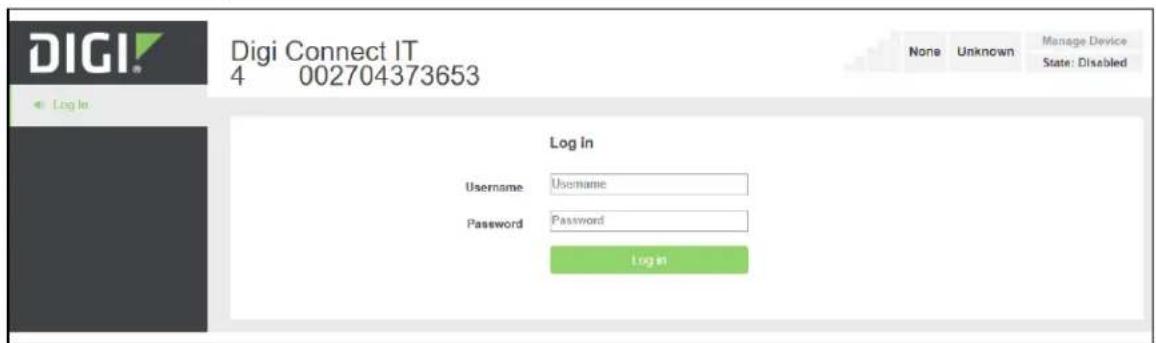
- Enter the user name and password:
■ User Name: The default user name is: root
■ Password: The default password for the Connect IT is printed on the label attached to the device. Once you are logged in you can change the password.
- Click Log in. The Connect IT local web user interface appears.
Manually configure PC to connect to the Connect IT
To manually connect to the device, you must manually set an IP address on your PC to be able to communicate with the Connect IT.
- Select the Properties of the relevant network connection on the Windows PC.
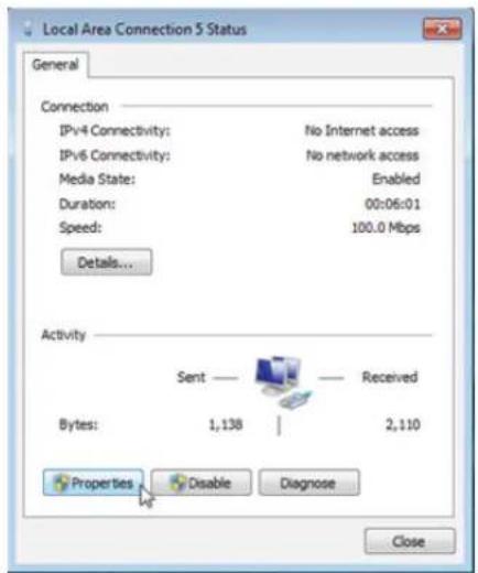
- Click the Internet Protocol Version 4 (TCP/IPv4) parameter.
-
Click Properties. The Internet Protocol Version 4 (TCP/IPv4) Properties dialog appears.
-
Configure with the following details:
■ IP address for PC: 192.168.210.2
■ Subnet: 255.255.255.0
■ Gateway: 192.168.210.1
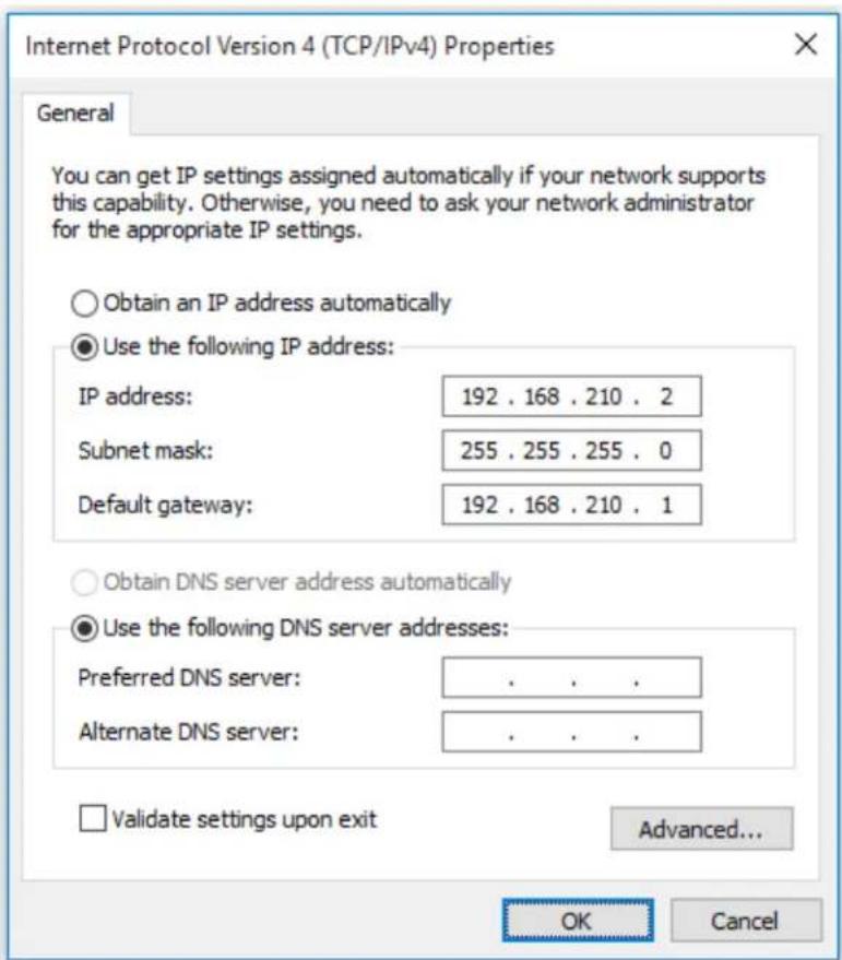
Log in to Remote Manager and access the Configuration screen
After you have created your Remote Manager account, you can log in.
Note See Create a Remote Manager account for instructions on how to create an account.
- In a web browser, type https://remotemanager.digi.com.
- Type your login credentials in the Username and Password fields.
Work with the web UI (web user interface) Log in to Remote Manager and access the Configuration screen
- Click Log in.
- Access the configuration screen.
a. Click Try Remote Manager 3.0 preview in the top right of the screen.
b. Click Devices in the left pane.
c. Double-click on the device you want to configure.
d. Click the Edit Configuration button.
Troubleshooting
Reset your device to the factory defaults.56.
Tips for improving cellular signal strength.56
Download a support report.56.
Reset your device to the factory defaults
You can reset the Connect IT to the factory default settings. Resetting the device to factory defaults performs the following actions:
■ Clears all configuration settings.
■ All firmware updates are deleted.
■ Deletes all user files, including Python scripts.
■ Regenerates SSH keys.
■ Clears event and system log files.
■ Creates a new event in the event log, indicating a factory reset.
Note While the settings are reset, the device's firmware version remains the same.
- Make sure that the Connect IT has been powered on for at least 30 seconds.
- Locate the Reset button on the back of the device.
- Press and hold the Reset button for 15 seconds.
- The device resets to factory defaults and then reboots automatically.
Tips for improving cellular signal strength
If the signal strength LEDs or the signal quality for your device indicate Poor or No servcie, try the following things to improve signal strength:
■ If available, connect a different set of antennas.
■ Purchase a Digi Antenna Extender Kit: Antenna Extender Kit, 1 m.
Download a support report
You can download a support report from the device to provide to technical support. The report file contains all of the current details for the device's state, and a full record of the system logs from the device.
See Download a support report file.
Hardware
Front panel and LEDs
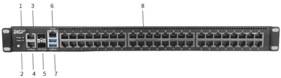
| Item Name Description | |
| 1 Power | The LED lights up when the power is supplied to the device and the device powered on.■ Solid blue: The LED is solid blue when the power source is connected and power is being supplied to the device.■ Flashing blue: The Connect IT is shutting down, caused by pressing the ACPI power button.■ Red: The LED is red when the power supply has failed. |
| 2 Status | The LED lights up when the Connect IT starts up or you have activated the find me feature.■ Flashing blue: The LED flashes blue once per second when the Connect IT starts up or you have activated the find me feature. When starting up, the WWAN Signal, WWAN Service, and Status LEDs on the back of the Connect IT also flash.■ Solid blue: The Connect IT initialization is complete.■ Red: The Connect IT has had start-up failure. |
| Item Name Description | ||
| 3 ETH2 | Indicates the status of the backup connection on the LAN.ETH2 is configured for LAN/DHCP server.SeeConnect hardware and connect to site network using an Ethernet LAN.The LED indicates the connection status:■ Flashing: The unit is attempting to establish a backup connection on the LAN.■ Solid: A backup network connection has been established on the LAN. | |
| 4 ETH1 | Indicates connection to Ethernet WAN network.ETH1 is configure for WAN/DHCP client. | |
| 5 | SFP1SFP2 | Connect an SFP+ module to the Connect IT.■ SFP1: Enabled for WAN\DHCP client. SFP1 is the bottom slot.■ SFP2: Enabled for LAN\DHCP server. SFP2 is the top slot.NoteWhen you use an SFP+ module, you cannot use the equivalent Ethernet port. For example, if you insert an SFP+ module into the SFP1 slot, you cannot use the ETH1 slot. If you insert an SFP+ module into the SFP2 slot, you cannot use the ETH2 slot.The LED indicates the connection status.■ Green: The LED lights green:○ 10 Gb/s: constant light○ 1 Gb/s: OFF light■ ACT: The LED is green. |
| 6 Console port | A console adapter accessory can be used with a straight through RJ45 cable to connect a serial port on a computer to the console port of the Connect IT.■ Left: The left LED for a port lights yellow.■ Right: The right LED for a port lights green.Behaviors: ON, OFF, slow blink, fast blink. | |
| 7 USB ports Connect a USB flash drive to the Connect IT for backup or logging. | ||
| Item Name Description | |
| 8 Serial ports | Connect equipment to a serial port to provide console access to the equipment through the cellular network. See Connect equipment to the Connect IT serial ports.■ Connect IT 16: serial ports 1-16.■ Connect IT 48: serial ports 1-48.The LED on the left lights:■ Yellow: There is activity on the port.■ Green: The port is in use.The LED on the right for ACT lights yellow. |
Back panel and LEDs

| Item Name | Description | |
| 1 | Power and fan item | Connect the power supply and fan unit to the device. For installation information, see Connect the power supplies and fans. |
| 2 | WWAN2 | |
| 3 | CORE module | The CORE module is used to complete a cellular connection. See Connect hardware and connect to a cellular network. |
| 3 | Antennas | Antennas can be attached if the module is used to complete a cellular connection. See Connect hardware and connect to a cellular network |
| 4 | WWAN1 | |
| 5 | Reset | Press this switch to reset the device. See Reset your device to the factory defaults. |
| 6 WWAN Signal | The LED indicates the strength of the cellular signal. The color relates to "bars" of service.■ LED off: no bars■ Red, slow flash: 0 bars■ Blue, slow flash: 1 or 2 bars■ Blue, fast flash: 3 or 4 bars■ Blue, solid: 5 bars | |
| 7 WWAN Service | The LED indicates the status of the cellular service.■ Off: No modem detected in the slot.■ Slow flashing blue: The LED flashed once per second when the modem is detected and is initializing.■ Fast flashing blue: The LED flashes two times a second when the modem is connecting to the cellular network.■ Solid blue: A modem is detected and a cellular data session is established.■ Solid red: A SIM card is not detected in the modem. | |
| 8 PSU1 | The LED indicates the status of the PS1 power supply and fan unit.■ Off: No power is connected to the PS1 power supply.■ Solid blue: Power is connected to the PS1 power supply and is in use by the Connect IT.■ Flashing blue: Power is connected to the PS1 power supply, but is it unusable. | |
| 9 PSU2 | The LED indicates the status of the PS2 power supply and fan unit.■ Off: No power is connected to the PS2 power supply.■ Solid blue: Power is connected to the PS2 power supply and is in use by the Connect IT.■ Flashing blue: Power is connected to the PS2 power supply, but is it unusable. | |
| 10 Status | The LED lights up when the Connect IT starts up or you have activated the find me feature.■ Flashing blue: The LED flashes blue once per second when the Connect IT starts up or you have activated the find me feature. When starting up, the WWAN Signal, WWAN Service, and Status LEDs on the back of the Connect IT also flash.■ Solid blue: The Connect IT initialization is complete.■ Red: The Connect IT has had start-up failure. | |
| 11 Fan | Connect the fan unit to the device.For installation information, see Connect the power supplies and fans. | |
| 12 Power and fan item | Connect the second power supply and fan unit to the device.For installation information, see Connect the power supplies and fans. | |
Hardware specifications
| Hardware Description | |
| Input rating for redundant dual power | ■ 100-240 VAC■ 50-60 Hz■ 2.4 A maximum for each power supply |
| Operating temperature 0°C - 50°C |
Power supply
The Connect IT 16 or 48 must be operated only with power supplies from a Digi-provided power supply kit, either ITPS-PSIK (for Port Side Air Intake) or ITPS-PSIK (for Port Side Air Exhaust), as appropriate for the device installation location.
Electrical rating
The Connect IT 16 and Connect IT 48 devices require an appropriate power cable that meets national standards to connect to a standard outlet. The appropriate requirements are listed per region:
■ EU/International: VDE Mark, conforming to IEC 60083, IEC 60227, or IEC 60320, with C13 to the appropriate national mains connector, 2 x 0.75 mm2.
Hardware Mounting options
■ USA/Canada: UR Mark, conforming to UL 62, UL 817, or CSA-C22.2, with C13 to 1-15P, 5-15P, or NEMA locking connector, 18 AWG.
Mounting options
Install the Connect IT device on a 19" rack using the provided rack mount ears. If necessary, the ears can be moved to the rear side of the device.
Regulatory and safety information
Safety warnings
Review the following safety warnings for Connect IT 16/48.

WARNING! Notice the following safety warnings:
- Risk of explosion if battery is replaced by incorrect battery type. Dispose of used batteries according to the instructions.
■ Use UL-recognized Laser Class I Optical Transceiver product.
■ Ensure that the power cord is connected to a socket-outlet with earthing connection.
■ This appliance does not contain any user-serviceable parts. Never open the equipment. For safety reasons, the equipment should be opened only by qualified personnel.

WARNING! Risk of electric shock.
WARNING! Disconnect all energy sources.

AVERTISSEMENT! Notice the following safety warnings:
Power supply and supplemental fan module considerations
When you install or remove a power supply or the supplemental fan, be aware of the following requirements:
■ Main power must be removed from both power supplies before installation or removal of either power supply or the supplemental fan.
- Do not force a fan module or power supply into its slot. This may cause damage to the connector if it is not properly aligned.
■ A fan or power supply that is not fully connected can cause the system to not operate properly.
- Do not operate the device with one power supply module empty. Proper device cooling requires both modules and the supplemental fan to be present.
■ The device will continue to operate if one of the power supplies and/or the supplemental fan are in a failed state unless the internal temperature exceeds a safe limit. If this occurs the device will write a failure message to the internal flash log file and then shut down.
■ Make sure that both power supplies and the supplemental fan module are properly seated and the thumb screws tightened before applying power to the unit.
Information access
Manuals and further information are provided.
Warning messages for replacing batteries and for restricted access area requirements are available in this manual. See Safety warnings.
The Digi Connect IT ^® 16/48 User Guide is accessible online.

- Digi Connect IT® 16/48
- User Guide
- Revision history—90002332
- Trademarks and copyright
- Disclaimers
- Warranty
- Send comments
- Customer support
- Contents
- Digi Connect IT® 16/48 User Guide
- Get started with Connect IT 16/48
- Connect equipment to the Connect IT serial ports
- Configure the Connect IT 16/48
- Work with the web UI (web user interface)
- Troubleshooting
- Hardware
- Regulatory and safety information
- Connect IT 16 and 48 key features
- Verify product components
- Included equipment
- Required additional equipment
- Optional additional equipment
- Optional equipment
- Cellular ONLY: Insert the CORE module
- Prerequisites
- Connect the power supplies and fans
- Optional: Connect SFP+ modules
- Connect the hardware
- Connect hardware and connect to site network using an Ethernet LAN
- Connect hardware and connect to a cellular network
- Serial connector pinout
- Change a Connect IT password
- Manage users and groups
- Create a group
- Configure an access control group
- Create a user profile and assign an access control group
- Configure two-factor authentication for a user
- Update the firmware on the Connect IT
- Update Connect IT firmware from the local web user interface
- Update the firmware on Connect IT from Remote Manager
- Download the Connect IT firmware to your PC
- Configure authentication methods
- Configure idle timeout
- Update modem firmware from the local web user interface
- Configure Remote Power Management
- Configure the Connect IT to connect to a power controller
- ■ Serial Connection
- ■ Network Connection
- Configure a serial port for Power Management
- Connect a power controller to the Connect IT serial port
- Configure communication with a power controller
- Serial
- TCP
- Create an access control group for power management and assign to users
- View power controller status and manage power (Administrators)
- View power controller status
- Change the power state
- View power manager log
- Control the outlet power from a terminal (all users)
- Configure a serial port
- Configure the connection settings for a serial port
- Monitor serial port changes
- Enable a Telnet connection on the serial port
- Enable a TCP connection on the serial port
- Enable an SSH connection on the serial port
- Click Save or Apply.
- Configure a modem
- Configure the modem
- Click Save or Apply.
- Define a custom APN list
- Configure a custom gateway for the modem
- Configure an IPv4 network interface for the modem
- Configure an IPv6 network interface for the modem
- Configure the network
- Configure the Connect IT name from the local web user interface
- Configure a VPN
- Configure an IPsec tunnel for a VPN
- Configure an OpenVPN server
- Configure an IP tunnel for a VPN
- Back up, restore, and delete the configuration
- Back up the Connect IT configuration
- Restore the Connect IT configuration
- Delete the Connect IT configuration
- Configure the firewall
- Configure services
- Monitor the data from the Connect IT
- Reboot the Connect IT
- Immediately reboot the Connect IT from the local web user interface
- Immediately reboot the Connect IT from Remote Manager
- Schedule a reboot from the local web user interface
- Schedule system maintenance
- Synchronize system time
- View Connect IT status information
- Download an archive of the supported MIBs
- Download a support report file
- Configure and view events and logs
- View events information
- Configure log messages
- View system log information
- Log in to the local web user interface or Remote Manager
- Access a screen in the local web user interface or Remote Manager
- Add an item
- Access the Terminal screen
- Access help
- Save your changes
- Log in to the Connect IT local web user interface
- Manually configure PC to connect to the Connect IT
- Log in to Remote Manager and access the Configuration screen
- Reset your device to the factory defaults
- Tips for improving cellular signal strength
- Download a support report
- Front panel and LEDs
- Hardware specifications
- Power supply
- Electrical rating
- Mounting options
- Safety warnings
- WARNING! Notice the following safety warnings:
- AVERTISSEMENT! Notice the following safety warnings:
- Power supply and supplemental fan module considerations
- Information access
Brand : Digi
Model : Connect IT 16
Category : Server