SyncroIP DNB13TF22 - Security Camera Digimerge - Free user manual and instructions
Find the device manual for free SyncroIP DNB13TF22 Digimerge in PDF.


| Product Type | Security Camera |
| Model | SyncroIP DNB13TF22 |
| Brand | Digimerge |
| Image Sensor | 1/2.8" Progressive Scan CMOS |
| Resolution | 2 Megapixels (1920 x 1080) |
| Lens | 2.8mm Fixed Lens |
| Field of View | 105° (Horizontal) |
| Night Vision | Up to 30m IR Distance |
| Day/Night Mode | IR Cut Filter |
| Video Compression | H.265+, H.265, H.264+, H.264 |
| Frame Rate | 30fps @ 1080p |
| Power Supply | PoE (802.3af) / 12V DC |
| Power Consumption | Max 7W |
| Environmental Rating | IP66 Weatherproof |
| Operating Temperature | -30°C to 60°C |
| Dimensions (W x H x D) | 70 x 70 x 150 mm |
| Weight | 500 g |
| Warranty | 2 Years |
| Certifications | CE, FCC, RoHS |
| Mounting | Wall or Ceiling Mount |
| Audio | Built-in Microphone (optional) |
| Alarm I/O | 1 Input / 1 Output |
| Supported Protocols | IPv4, IPv6, HTTP, HTTPS, ONVIF (Profile G) |
Frequently Asked Questions - SyncroIP DNB13TF22 Digimerge
User questions about SyncroIP DNB13TF22 Digimerge
0 question about this device. Answer the ones you know or ask your own.
Ask a new question about this device
Download the instructions for your Security Camera in PDF format for free! Find your manual SyncroIP DNB13TF22 - Digimerge and take your electronic device back in hand. On this page are published all the documents necessary for the use of your device. SyncroIP DNB13TF22 by Digimerge.
USER MANUAL SyncroIP DNB13TF22 Digimerge
SyncrolP Series IP Cameras
Software Manual
natural_image
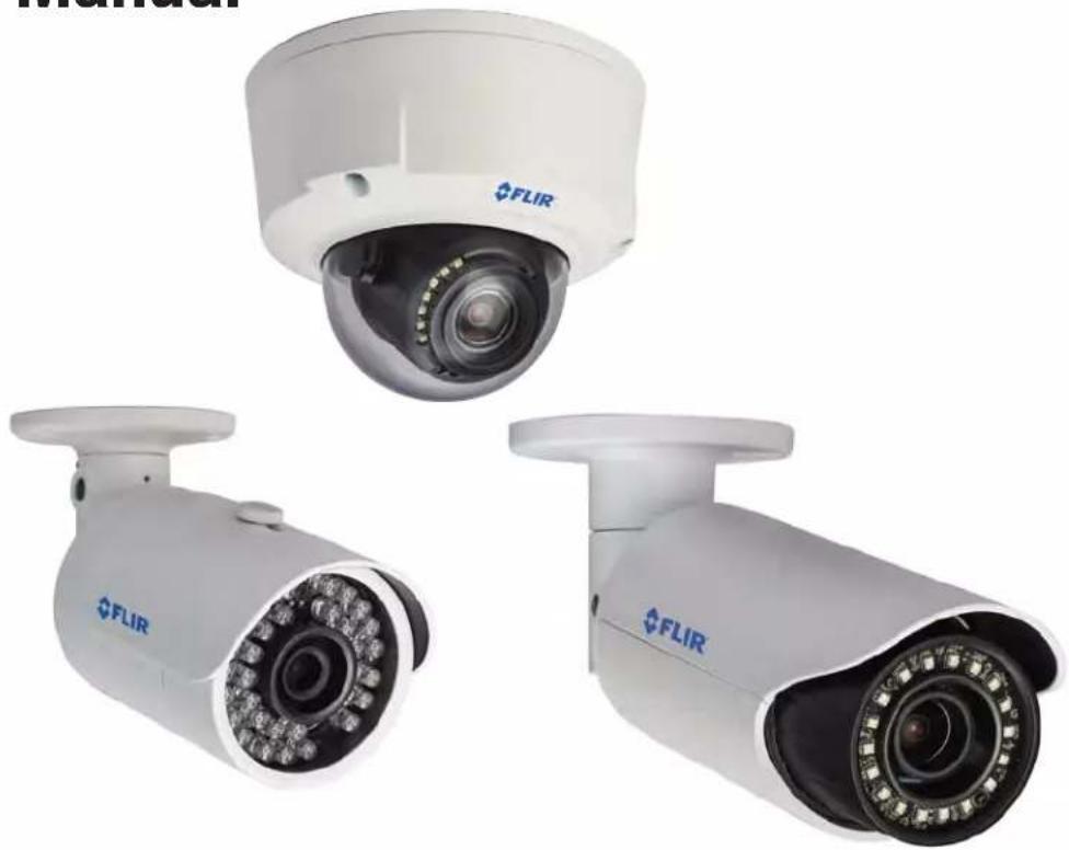
Three FLIR security cameras with visible lens and camera modules (no text or symbols on the cameras themselves)Instruction Manual
English Version 1.0
www.digimerge.com
www.flir.com/security
Copyright © 2013 Digimerge Technologies Inc., a FLIR Company
TABLE OF CONTENTS
Overview 1
Notes 1
Web Configuration Interface 2
Supported Browsers 2
Internet Explorer Setup 2
Safari Setup 2
Live View 3
PTZ Controls (PTZ Cameras Only) 5
PTZ Control Panel 5
Scan 5
Preset 6
Pattern 7
Goto 8
Setup 9
Camera 9
Conditions 9
Profile Management 10
Zoom and Focus (Motorized Lens Cameras Only) 11
Video 12
Snapshot 13
Overlay 13
Path 14
Network 14
TCP-IP 14
Connection 15
PPPoE (Unsupported) 16
DDNS 16
IP Filter 16
SMTP (Email) 17
UPnP 18
SNMP (Unsupported) 19
Multicast (Unsupported) 19
IEEE802 (Unsupported) 19
QOS (Unsupported) 19
Event 19
Video Detect 19
Video Masking (Unsupported) 21
Alarm (Cameras with Alarm I/O Only) 21
Warning 22
No SD Card 22
Capacity Warning 23
SD Card Error 23
Disconnection 24
IP Conflict 24
Storage 25
Record Schedule 25
Snapshot Schedule 25
Holiday Schedule 26
Destination - Path 26
Destination - Local 27
Destination - FTP 27
Record Control 28
System 28
General 28
General - Date & Time 29
Account 29
Default 32
Import/Export 32
Auto Maintain 33
Upgrade 33
Information 34
Version 34
Log 34
Playback (Cameras with microSD Only) 35
Playback Controls 36
Backing up Video Files 36
Upgrade Tool 38
Installing a Firmware Upgrade Over the LAN 38
Installing a Firmware Upgrade Over the Internet 39
FLIR SyncrolP Central Management Software For PC 41
System Requirements 41
Installing FLIR SyncrolP CMS 42
Adding an IP camera from the Local Area Network (LAN) 42
Adding an IP camera using a DDNS address 44
CMS Live Viewing Overview 46
Configuring Projects 47
Running Tasks and Projects 48
Using E-Map 49
Configuring E-Map 49
Opening Cameras from E-Map 50
Configuring the CMS 51
Configuring CMS Options 51
Changing the CMS Admin Password 52
Adding User Accounts to the CMS 53
Multi-Monitor Support 54
Opening Cameras in Secondary Monitors 54
Managing Secondary Monitors 54
Smartphone and Tablet Apps 56
iPhone 56
System Requirements 56
Prerequisites 56
Connecting to your IP camera on an iPhone 56
FLIR SyncrolP NVR Interface 58
Viewing Videos with Local File 58
Using Playback Mode on iPhone 59
Enabling Push Notifications 60
Device Manager 61
iPad 62
System Requirements 62
Prerequisites 62
Connecting to your IP camera on an iPad 62
FLIR SyncrolP NVR HD Interface 64
Device Manager 64
Using Playback Mode on iPad 65
Enabling Push Notifications 66
Android Phones 67
Compatible Devices 67
Prerequisites 67
Connecting to your IP Camera on an Android Phone 67
FLIR SyncrolP NVR Interface 69
Viewing Snapshots and Videos with Local Files 70
Using Playback Mode on Android Phones 70
Enabling Push Notifications 71
Device Manager 73
Android Tablets 73
System Requirements 73
Prerequisites 73
Connecting to your IP Camera on an Android Tablet 73
FLIR SyncrolP NVR HD Interface 75
Using Playback Mode on Android Tablets 76
Enabling Push Notifications 77
Device Manager 78
OVERVIEW
This manual covers the following topics related to your FLIR SyncrolP camera:
- Web browser configuration interface (page 2).
- Firmware update tool (page 38).
• PC CMS Software (page 41). - Smartphone / tablet apps (page 56).
Notes
- For physical installation instructions, please refer to the Quick Connection Guide for your camera model.
- The following models have a different web interface and supporting software: DND13TL2, DNB14L2, DNB13TL2, DNV14TL2, DNE14TL2. For instructions, please refer to the respective manual for these cameras.
WEB CONFIGURATION INTERFACE
The camera includes a built-in web interface that can be accessed using a web browser.
Supported Browsers
- Google Chrome, Mozilla Firefox, and Apple Safari® (via Webplugin)
- Microsoft Internet Explorer® 8.0 or later, 32-bit version (via ActiveX®)
Internet Explorer Setup
- Open Internet Explorer and enter the camera's IP address in the address bar in the following format: http://IP address:HTTP Port.
• For example: http://192.168.0.100:80
- A notification bar appears asking if you would like to install ActiveX® plugins. Click Install or Allow to install the plugins.
This webpage wants to run the following add-on: 'Flir Systems' from 'FLIR Systems, Inc.'. What's the risk?
Click Allow or Install
- Enter the camera user name (default: admin) and password (default: admin) and click Login.

Safari Setup
- Open Safari® and enter the camera's IP address in the address bar in the following format: http://IP address:HTTP Port.
• For example: http://192.168.0.100:80
- Enter the camera user name (default: admin) and password (default: admin) and click Login.

- Click Please click here to download and install the plug-in.

- Double-click we bplugin.pkg in the downloads list to install. Follow the prompts to install.

NOTE: If video from the camera does not appear after installation, quit Safari by right-clicking on the Safari icon in the dock and then selecting Quit. Then restart Safari and log back into your camera.
Live View
Upon login, the web interface opens to the Live View.
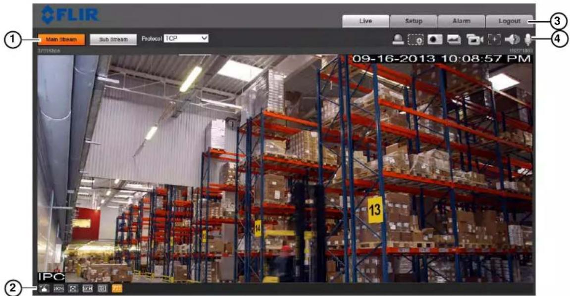
NOTE: Some functions are not available on all IP camera models, based on the features available.
- S stream/Protocol Select: Allows you to select the video stream and protocol used in Live View.
- Main Stream: Click to view the Main Stream. The Main Stream provides better picture quality and resolution, but requires higher bandwidth.
- Sub Stream: Click to view the Sub Stream. The Sub Stream is recommended for better performance when viewing the camera remotely.
- Protocol: Select the protocol that will be used to stream video: TCP or UDP.
NOTE: Multicast is not supported.
2. Video Display Controls

• Color Settings: Click to open color settings.

- 100% Original Size: Click to view the video in its original size. This depends on the resolution and if you are viewing the Main Stream or Sub Stream.
• Full Screen: Click to view the video in full screen. Double-click or press ESC to exit full screen.
- Width/Height Ratio: Click select Original to use the original proportions of the image or Adaptive to adapt the image proportions to the size of the screen.
• Realtime/Fluency: Click to select Realtime, Normal, or Fluency.
- PTZ Controls (PTZ cameras only): Click to hide/show PTZ camera controls. For details, see "PTZ Controls (PTZ Cameras Only)" on page 5.
3. Menu Tabs
• Live: Click to access Live View.
- Playback: Click to playback video from the camera's microSD card (cameras that support microSD only).
- Setup: Click to setup camera functions.
- Alarm: Click to configure alarms.
- Logout: Log out of the camera.
4. Live View Functions

- Alarm Output: Click to activate an alarm output device connected to the camera (cameras with alarm I/O only).
- Digital Zoom: Click to activate digital zoom mode. Then, click-and-drag in the video area to select an area to zoom in.
- Snapshot: Click to save a snapshot from the camera to your computer hard drive. To configure the folder where snapshots are saved, see "Path" on page 14.
NOTE: Depending on your computer's security settings, you may need to run your browser as administrator to save snapshots or manual recordings.
- Triple Snapshot: Sav e the next three frames from the camera as snapshots.
- Manual Record: Click to start manually recording live video to your computer hard drive. Click again to stop recording. To configure the folder where manual recordings are saved, see "Path" on page 14.
- Manual Focus (motorized lens cameras only): Click to display the AF Peak and AF Max parameters for auto focus. The closer AF Peak and AF Max are, the better the focus effect is. To configure auto focus, see "Zoom and Focus (Motorized Lens Cameras Only)" on page 11.
- Audio Output: Click to mute/un-mute audio coming from the camera (audio-enabled cameras only; must have self-powered microphone connected to the camera).
- Intercom: Click to activate the intercom to the camera (audio-enabled cameras only; must have amplifier or speakers connected to the camera.
• Help: Click to access the built-in help file.
PTZ Controls (PTZ Cameras Only)
From Live View, click to open the PTZ control panel.
PTZ Control Panel

Scan
You can use the Scan function to have the camera move automatically between two points.
To configure scan function:
- Select Scan under PTZ Settings.

- Click Set.
- Move the camera into the desired left position and then click Set Left to save.
- Move the camera into the desired right position and then click Set Right to save.
- Click Save.
- Click Start to start the Scan.
Preset
You can save preset positions in the camera to recall them later.
To save presets:
- Select Pres et under PTZ Settings.
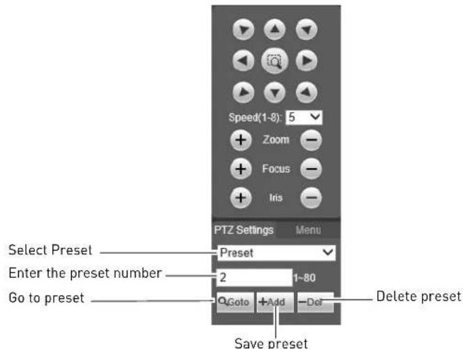
- Enter the number of the preset you would like to save.
- Move the camera into the desired position.
- Click Add to save the preset.
To go to a preset:
- Enter the number of the preset you would like to go to.
- Click Go to.
To delete presets:
-
Enter the number of the preset you would like to save.
-
Click Del.
Pattern
You can use the pattern function to record a series of camera movements to recall later.
To save a pattern:
- Select Pattern under PTZ settings.

-
Enter the number of the pattern you would like to save.
-
Click Add.
-
Click Start Rec. Use the PTZ controls to save a series of movements.
-
When you finish recording the pattern, click Stop Rec.
To run a pattern:
- Click Start.
Goto
The Goto function allows you to move the camera to a position with specified parameters.

To move the camera to a specified position:
- Select Go to under PTZ settings.
- Enter the Horizontal Angle you would like to move the camera to between 0\~3550.
- Enter the Vertical Angle you would like to move the camera to between 0\~900.
- Enter the Zoom level between 1\~128.
- Click Go to go to the specified position.
Setup
The Setup menus allow you to configure camera settings.
Camera
Conditions
The Conditions menu allows you to configure the image sensor settings for the camera. As you make adjustments, the effects will be shown in the video display.
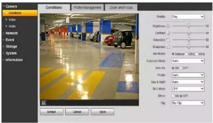
NOTE: Some settings described below may not be available, depending on the features of your camera model.
To configure the image sensor settings:
-
Configure the following:
-
Profile: Select the camera settings profile you would like to configure: Day, Night, or Normal.
- Brightness: Adjust the brightness of the image between 0 and 100.
- Contrast: Adjust the contrast of the image between 0 and 100.
- Saturation: Adjust the color saturation of the image between 0 and 100.
- Sharpness: Adjust the sharpness of the image between 0 and 100. Higher sharpness will make edges in the image clearer, but may increase noise in the picture.
-
Anti-flicker: Select the anti-flicker mode depending on the environment:
-
Outdoor: The system will use the exposure mode to adjust for lighting.
- 50Hz: The system will compensate for lighting using 50Hz AC power (i.e. for Europe).
- 60Hz: The system will compensate for lighting using 60Hz AC power (i.e. for North America).
- Exposure: Select the exposure mode.
- Auto: The system will automatically adjust the brightness and exposure based on the environment.
-
Low Noise: The system will automatically adjust the gain to reduce the amount of noise in the image. Set the minimum and maximum Gain Scope. Increasing the max gain will increase the noise reduction.
-
Low Motion Blur: The system will automatically adjust the shutter to reduce motion trails in the image. Set the minimum and maximum Shutter Scope.
- Manual: Configure manual exposure settings. Configure the Shutter Regulate and Gain Scope.
- Profile: Select the white balance mode.
• Auto: Automatic white balance.
- Sunny: White balance mode for daylight.
• Night: White balance mode for night time.
- Customized: Manual white balance. Use the sliders to configure the Red Control and Blue Control.
- Auto Iris (auto iris cameras only): Select ON to enable auto iris or OFF to disable auto iris.
- Day & Night: Select one of the following day / night modes.
• Color: Camera will be in day mode at all times.
- Auto: Camera will automatically change between day and night mode based on the lighting.
- B/W: Camera will be in black and white at all times.
- BLC Mode: Select one of the following modes:
- BLC (Backlight Compensation): The camera automatically adjusts the exposure for a clearer image in the darkest areas of the video. Click Default to use default settings or Customized to adjust the BLC area. The darker the area you select, the brighter the image will be.
- WDR(Wide Dynamic Range): The camera compensates for changes in brightness across the image to enhance the picture quality of both light and dark areas. Adjust the WDR level between 1 and 100.
- HLC (Highlight Compensation): The camera dims the brightest areas of the image to make them clearer. Adjust the HLC level between 1 and 100.
- Off: Disable this function.
- Mirror: Select ON to flip the camera left and right.
- Flip: Select one of the options to flip the image or No Flip to disable. Note that 90^ rotations are not supported if the Main Stream is set above 720p resolution.
- Click Save to save changes. Click Cancel to return to last saved configuration. Click Default to return to factory defaults.
Profile Management
The Profile Management tab allows you to set which Condition Profile to use at what times.
To configure the condition profile:
- Select one of the following options:
- Normal: Camera will use the Normal profile at all times.
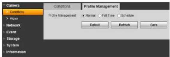
• Full Time: Select the profile the camera will use at all times.

- Schedule: Configure a schedule that the camera will use for Day (yellow) and Night (black) profiles. Click and drag in the time bar to set the schedule.
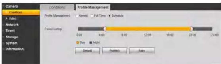
2. Click Save to save changes.
Zoom and Focus (Motorized Lens Cameras Only)
For motorized lens cameras, you can use the Zoom and Focus tab to adjust the lens.

- Zoom: Click +/- or use the slider to adjust the zoom level.
- Focus: Click +/- or use the slider to adjust the focus.
- Auto Focus: Click to have the camera automatically adjust the focus to the currently selected zoom level.
NOTE: Adjustments in this menu are automatically saved.
Video
The Video menu allows you to configure the encoding settings for the camera. Video settings are divided into Main Stream and Sub Stream.

To configure video quality settings:
- Check Ena ble under Sub Stream to enable the sub stream or uncheck to disable.
-
For the Main Stream and Sub Stream, configure the following:
-
Code Stream Type: For the Main Stream, select General to configure settings when motion is not detected or Motion to configure settings when motion is detected.
- Encode Mode: Select the encoding type: H.264 (Main H.264 profile), H.264H (High Profile H.264), H.264B (Baseline H.264 profile), MJPEG.
NOTE: A much higher bitrate and faster connection is required to maintain image quality using MJPEG. It is recommended to use H.264 unless you have special requirements.
- Resolution: Select the desired resolution for the video stream. There is a different recommended bit rate depending on the resolution selected.
NOTE: You may not set the resolution above 720p if the Flip function is activated.
• Frame Rate (FPS): Select the desired frame rate for the video stream between 1 and 30 FPS.
- Bit Rate Type: Select CBR (Constant Bit Rate) or VBR (Variable Bit Rate). If you select VBR, you can select the Video Quality between 1 (lowest) and 6 (best).
- Reference Bit Rate: Recommended bit rate range based on the resolution and frame rate settings you have selected.
- Bit Rate: Select the desired bit rate for each video stream or select Customized and enter the bit rate in Kbps.
- I Frame: Select the interval for I frames. It is recommended to select 2 unless you have special requirements.
- Under W atermark Settings, check to enable watermark to protect against video tampering.
- Under W atermark Character, enter the desired watermark text.
- Click Sav e to save changes.
Snapshot
The Snapshot menu allows you to configure images quality settings for snapshots.

To configure snapshots:
-
Configure the following:
-
Snapshot Type: Select General to configure snapshots taken using scheduled recording. Select Event to configure snapshots activated by alarms.
• Image Size: The image size of snapshots is the same as the resolution for the stream selected.
• Quality: Select the image quality for snapshots between 1 (lowest) and 6 (highest). - Snapshot Stream: Select Main Stream to take snapshots from the Main Stream or Sub Stream to take snapshots from the Sub Stream.
-
Interval: Select the interval between snapshots between 1 and 7 seconds.
-
Click Sav e to save changes.
Overlay
The Overlay tab allows you to configure the OSD text on the camera video display.
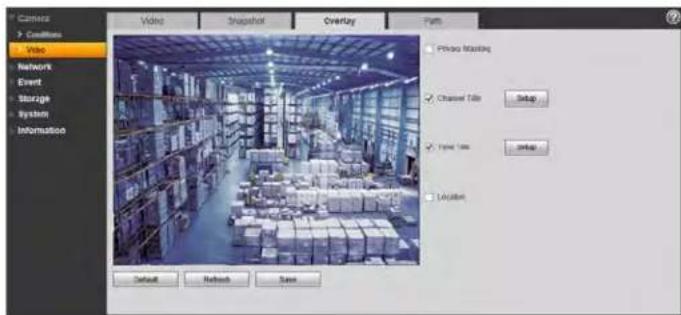
To configure the OSD:
-
Check Privacy Masking to enable privacy masking. Then, click Setup to configure privacy areas. You may have up to 4 privacy areas.
-
Click the corners of a privacy area to adjust the size of the privacy area.
- Right-click to delete the currently selected privacy area.
- Click and drag outside of the privacy areas to create a new privacy area.
-
Click Save to save changes.
-
Under Channel Title, check to show the channel title. Click Setup to enter a custom channel title.
-
Under Time Title, check to show the time. Click Setup and then check Week Display to show the day of the week.
-
Under Location, check to add a custom message, and then click Setup to enter a custom message up to 5 lines.
- Click Sav e to save changes.
Path
The Path tab allows you to configure the folder where snapshots and manual recordings are saved.
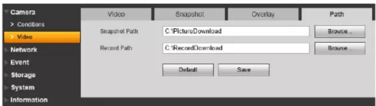
To configure the recording and snapshot folder:
-
Configure the following:
-
Snapshot Path: The folder on your hard drive where snapshots are stored. Click Browse to select a different folder.
-
Record Path: The folder on your hard drive where manual recordings are stored. Click Browse to select a different folder.
-
Click Sav e to save changes.
Network
TCP-IP
The TCP-IP menu allows you to configure the camera for DHCP or Static IP addressing.

To configure IP address settings:
- Under Host Name, enter the Host Name for the camera up to 32 characters.
-
Under IP Version, select IPV4 or IPV6.
-
Under Mode, select Static or DHCP. If you select Static, configure the IP Address, Subnet Mask, Default Gateway, Preferred DNS Server, and Alternate DNS Server.
- Click Save to save changes.
Connection
The Connection menu allows you to configure the camera ports and maximum connections to the camera. You must port forward the HTTP (default: 80) and TCP (default: 35000) port numbers on your router to enable remote connection to your camera
NOTE: If you are not using an and are setting up multiple cameras in the same network for remote access, you must assign unique TCP and HTTP ports for each camera. Two cameras cannot share the same port number.

To configure connection settings and ports:
- Under Max C onnection, enter the maximum number of devices that can connect to the camera at the same time between 1 and 20.
-
Configure the following port settings:
-
TCP Port: Enter the TCP (Client) Port number (default: 35000). The TCP port is used to stream video to remote computers or mobile devices. The TCP Port must be port forwarded to enable remote connection to your camera.
- UDP Port: Enter the UDP Port number (default: 37778). The UDP Port is used for special applications only.
- HTTP Port: Enter the HTTP Port (default: 80). The HTTP Port is used to access the camera's web interface. The HTTP Port must be port forwarded to enable remote access.
NOTE: If you change the HTTP Port to anything other than 80, you must enter colon (:) and the HTTP port in your web browser to access the camera (e.g. http://tomsmith.myddns-flir.com:85).
- RTSP Port: Enter the RTSP Port (default: 554). The RTSP Port is used for special applications.
-
(Optional) To enable HTTPS, check HTTPS On. To connect to the camera using HTTPS, you must forward the HTTPS port (default: 443) on your router. You must also connect to the camera using the following format:
-
https://IP or DDNS address:HTTPS Port
• For example: https://tomsmith.myddns-flir.com:443 -
(Optional) To configure the HTTPS port, enter the custom port number under HTTPS Port (default: 443).
- Click Sav e to save changes.
PPPoE (Unsupported)
DDNS
The DDNS menu allows you to set up the camera with a free FLIR DDNS account for remote connectivity. You can register for a FLIR DDNS account at ddns.myddns-flir.com.

To configure DDNS:
- Under Server Type, check the checkbox and select FlirDDNS.
- Under Do main Name, enter the Domain Name from the confirmation email you received after registering for DDNS.
- Under Us ername, enter the User Name from the confirmation email.
- Under Password, enter the Password from the confirmation email.
- Click Sav e.
NOTE: It may take between 10\~15 minutes for the DDNS server to update with your new DDNS address.
IP Filter
The IP Filter allows you to create a white list of device MAC or IP addresses that can access the camera. If you use the IP filter menu, devices that are not on the white list will not be able to
remotely connect to the camera.


If you enable the IP filter the camera will block any device that is not listed. Make sure the correct devices are added to the list, or you may not be able to access the camera.
To filter connections based on IP or MAC addresses:
- Click A dd IP/MAC.
- Select IP A address or MAC Address and then enter the address of the device you would like to add to the white list.
- Click Sav e.
- Check T rusted Sites.
- Click Sav e to save changes.
SMTP (Email)
The SMTP menu allows you to set up email alerts for motion or alarms.

To configure SMTP Settings:
-
Under SM TP Server, enter the SMTP server address.
-
Under Port, enter the Port used by the server.
- Check Anonymity if the server allows anonymous logins or uncheck to enter credentials to access the server.
- Under Us ername, enter the user name of the sender's account.
- Under Pa ssword, enter the password of the sender's account.
- Under Se nder, enter the sender's email account.
- If the server uses encryption, select SS L or TLS under Authentication.
- Under Interv al, select the interval for sending email alerts. The system will only send email alerts after this interval has passed.
- Check He alth Mail to enable the camera to send health alerts. If you enable health alerts, enter the interval in seconds under Update Period.
- Click Email Test to send a test email using the settings you have entered.
- Click Save to save changes.
UPnP
UPnP allows you to map port numbers between the LAN and the Internet. Depending on your router version, you may need to disable UPnP function.

Bonjour
The Bonjour menu allows you to enable the Bonjour service to easily detect the camera on a local network when using a Mac.
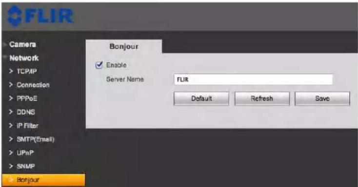
To enable / disable the Bonjour service:
- Check Ena ble to enable Bonjour or uncheck to disable.
- Under Se rver Name, enter the name of the camera that will show up when accessing the camera through Bonjour in Safari.
- Click Sav e to save changes.
To access the camera through Bonjour:
- In Safari, click to open the Bookmarks menu.
- Click Bonj our, the IP Camera will appear in the list.

- Double-click the IP camera to open it in a browser tab.
SNMP (Unsupported)
Multicast (Unsupported)
IEEE802 (Unsupported)
QOS (Unsupported)
Event
Video Detect
The Video Detect menu allows you to set up motion detection and recording.
NOTE: Recording functions require an FTP server or microSD card. Some camera models do not support microSD recording.

To set up motion detection settings:
-
Check Enable to enable motion detection.
-
To configure a schedule when motion detection will be activated, click Setup next to Working Period.

- Select the day you would like to configure by clicking the Setup buttons. You can apply the same schedule to multiple days using the checkboxes.
- Configure up to 6 time periods when motion detection will be activated.
-
Click Save. Repeat the steps above if you would like to apply a different schedule to different days.
-
Under Anti-dither, enter the anti-dither time. After a motion event occurs and motion stops, if motion is detected within the anti-dither time, the system continues the motion event and includes the new motion within the first event, rather than creating a new motion event.
-
To configure the motion grid, click Setup next to Area.
-
Areas where motion detection is enable are represented by yellow boxes.
• To resize an area, click on one of the corners and drag. - To move an area, click inside and drag.
- Right-click to delete the selected area.
- Click and drag outside of all areas to draw a new area. You may have up to 4 motion areas.
-
Use the sliders to adjust the Sensitivity and Threshold for motion detection.
-
The Sensitivity determines how sensitive the camera is to motion. For example, if the sensitivity is high, small amounts of motion will score higher on the graph. It is recommended to select a Sensitivity between 30\~70.
- The Threshold determines how much motion is required to trigger an alarm or recording. It is represented by the horizontal line on the graph. If the amount of motion in the area exceeds this line, it will trigger an alert. It is recommended to select a Threshold between 10\~50.
• Each motion area can have a separate Sensitivity and Threshold value.
- Click Save.

- Check Record to record when motion is detected. microSD or FTP recording must be configured to use this function.
- Enter number of seconds the camera will record after motion is detected under Record Delay.
- Check Relay Out to trigger an external alarm device when the camera detects motion. The camera must have an Alarm Output to use this function.
- Enter the number of seconds the camera will trigger the external device under Alarm Delay.
- Check Send Email for the camera to send an email alert when motion is detected. Email settings must be configured to receive email alerts.
- Check Snapshot for the camera to save a snapshot when motion is detected. microSD or FTP recording must be configured to use this function.
- Click Save to save changes.
Video Masking (Unsupported)
Alarm (Cameras with Alarm I/O Only)
The Alarm menu allows you to configure settings for alarm devices. Your camera must have an alarm I/O connector to use alarm devices.
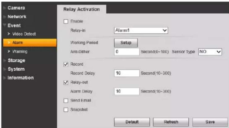
To configure alarm device settings:
1. Configure the following:
- Under Relay-In, select the alarm device you would like to configure.
- Check Enable to enable the selected alarm In device.
- Click Setup next to Working Period to set a schedule for alarm device activation.
- Under Anti-Dither, enter the latch time in seconds.
- Under Sensor Type, select NO (Normally Open) or NC (Normally Closed) depending on the type of sensor used.
- Check Record to record when a sensor device is triggered.
- Under Record Delay, enter the amount of time the system will record when a sensor device is triggered.
- Check Relay-out to activate an alarm output device (e.g. strobe light) when the sensor device is triggered. The camera must have an alarm output to use this feature.
- Check Send Email for the camera to send out an alert email when the sensor device is triggered.
- Check Snapshot for the camera to save a snapshot to FTP or microSD when the sensor device is triggered.
2. Click Sav e to save changes.
Warning
The Warning menu allows you to configure system warnings. The following system warning types are supported: No SD Card, SD card Capacity Warning, SD Card Error, Disconnection, and IP Conflict.
NOTE: No SD Card, Capacity Warning, and SD Card Error are only available on cameras that support microSD.
No SD Card
A No SD Card error occurs if recording is set in the camera, but there is no microSD or SD card installed.

To configure No SD Card errors:
- Check Ena ble to enable No SD Card errors.
- Check Relay-out to trigger an alarm out device when No SD Card errors occur. Under Alarm Delay, enter the number of seconds the alarm out device will be activated.
NOTE: Relay-out is only available if your camera supports alarm output.
- Check Send Email to send an email alert when No SD Card errors occur.
Capacity Warning
A Capacity Warning occurs when the recording destination (microSD or SD card or FTP server) reaches capacity.

To configure Capacity Warnings:
- Check Ena ble to enable Capacity Warnings.
- Under Cap acity Limit, set the percentage of free space on the recording destination that will trigger a Capacity Warning. For example, if you enter 10% and your microSD card is 1GB, a warning will occur when there is only 100MB of free space remaining.
- Check Relay-out to trigger an alarm out device when Capacity Warnings occur. Under Alarm Delay, enter the number of seconds the alarm out device will be activated.
NOTE: Relay-out is only available if your camera supports alarm output.
- Check Send Email to send an email alert when Capacity Warnings occur.
- Click Sav e to save changes.
SD Card Error
An SD Card Error occurs if an error occurs recording to the microSD or SD card (for example if the SD card is damaged or is using the wrong file system).

To configure SD Card Errors:
- Check Ena ble to enable SD Card Errors.
- Check Relay-out to trigger an alarm out device when SD Card Errors occur. Under Alarm Delay, enter the number of seconds the alarm out device will be activated.
NOTE: Relay-out is only available if your camera supports alarm output.
- Check Send Email to send an email alert when SD Card Errors occur.
- Click Sav e to save changes.
Disconnection
A Disconnection error occurs if the camera is disconnected from the network.
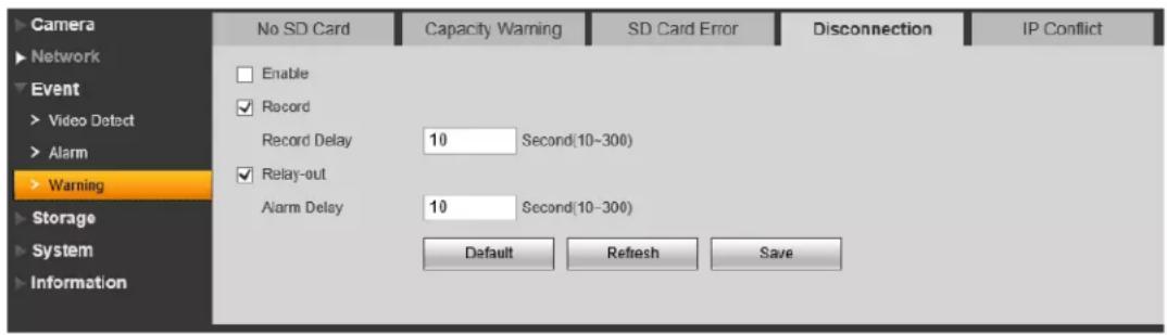
To configure Disconnection Errors:
- Check Ena ble to enable Disconnection errors.
- Check Record to record to the microSD or SD card when Disconnection errors occur.
NOTE: The camera must support microSD or SD card recording to use this function.
-
Under Record Delay, enter the number of seconds the camera will record after a Disconnection error.
-
Check Relay-out to trigger an alarm out device when Disconnection errors occur. Under Alarm Delay, enter the number of seconds the alarm out device will be activated.
NOTE: Relay-out is only available if your camera supports alarm output.
-
Check Send Email to send an email alert when Disconnection errors occur.
-
Click Sav e to save changes.
IP Conflict
An IP Conflict error occurs if another device is assigned the same IP address as the IP camera.

To configure IP Conflict errors:
- Check Ena ble to enable IP Conflict errors.
- Check Record to record to the microSD or SD card when IP Conflict errors occur.
NOTE: The camera must support microSD or SD card recording to use this function.
-
Under Record Delay, enter the number of seconds the camera will record after an IP Conflict error.
-
Check Relay-out to trigger an alarm out device when IP Conflict errors occur. Under Alarm Delay, enter the number of seconds the alarm out device will be activated.
NOTE: Relay-out is only available if your camera supports alarm output.
-
Check Send Email to send an email alert when IP Conflict errors occur.
-
Click Save to save changes.
Storage
The Storage menu allows you to configure recording settings.
Record Schedule
The Record Schedule determines the schedule for video recording to SD card or FTP.

To configure the recording schedule:
- Click Setup next to the day you would like to configure.
- Use the checkboxes if you want to copy the schedule to other days.
-
Configure up to 6 time periods for recording. For each period, enter a time range and check the recording types you would like to enable during that period:
-
General: Continuous recording.
- Motion: Motion activated recording.
- Alarm: Alarm activated recording.

- Click Sav e.
Snapshot Schedule
The Snapshot schedule determines the schedule for snapshot recording.
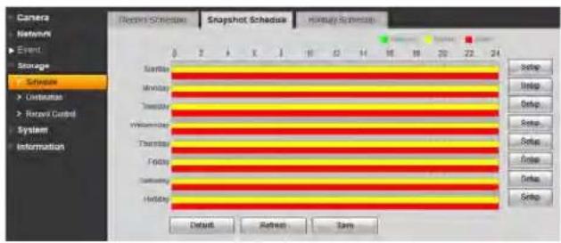
To configure the snapshot schedule:
- Click Setup next to the day you would like to configure.
- Use the checkboxes if you want to copy the schedule to other days.
-
Configure up to 6 time periods for recording. For each period, enter a time range and check the recording types you would like to enable during that period:
-
General: Continuous recording.
- Motion: Motion activated recording.
- Alarm: Alarm activated recording.

- Click Sav e.
Holiday Schedule
The Holiday Schedule allows you to set certain days of the year as holidays.
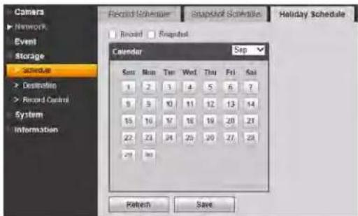
To configure the holiday schedule:
- Check Record or Snapshot to enable holidays for that recording type.
- Use the calendar to select which days are holidays.
- Click Sav e.
Destination - Path
The Path tab allows you to select if the camera records to microSD or FTP.
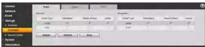
To select the recording destination:
- Under Record or Snapshot, check Local to record to the microSD card or FTP to record to FTP. For video recording or snapshot recording, you cannot record to both microSD and FTP.
- Click Sav e.
Destination - Local
The Local tab allows you to format or configure the microSD card installed in the camera.

- Click Read Only to set the microSD card on read only mode. This disables microSD recording.
- Click Read & Write to enable recording on the microSD card.
- Click Hot Swap to unmount the microSD card if you would like to eject it from the camera.
- Click Format and then click Yes to format the microSD card. The camera will reboot once the format is completed.
Destination - FTP
The FTP tab allows you to set up settings for recording to an FTP server.
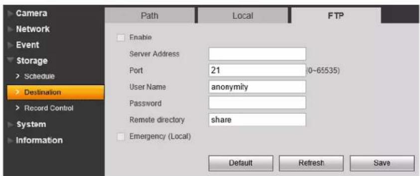
To set up FTP settings:
- Check Ena ble to enable recording to FTP.
-
Configure the following:
-
Server Address: Enter the IP address or DNS address of the FTP server.
- Port: Enter the FTP server port number.
- User Name: Enter the user name for the FTP server.
- Password: Enter the password for the FTP server.
- Remote directory: Enter the recording directory on the FTP server (e.g. share).
NOTE: The recording directory must be located one level below the root directory. For example share is acceptable, but not share/.
- Check Emergency (Local) to enable microSD recording if the FTP server cannot be reached.
- Click Save to save changes.
Record Control
The Record Control menu allows you to configure recording parameters for the camera.

To configure recording parameters:
- Under Pa ck Duration, enter the duration in minutes that the camera will use to pack video files.
- Under Pr e-event Record, enter the duration in seconds that the camera will pre-record before motion events.
- Under Di sk Full, select Overwrite to overwrite recordings when the recording medium is full or select Stop to stop recording when the recording medium is full.
- Under Record Mode, select Auto to record according to the schedule, select Manual to record continuously, or select Off to disable recording.
- Under R ercord Stream, select Main Stream to record using the Main Stream settings, or select Substream to record the substream.
- Click Sav e to save changes.
System
General
The General menu allows you to configure general camera settings.

To configure general camera settings:
- Under De vice Name, enter a name for the camera.
- Under Language, s elect the language that will be used for the web browser interface.
- Under Video Standa rd, select NTSC (North America) or PAL (Europe).
- Click Sav e.
General - Date & Time
The Date & Time tab allows you to set up date and time settings for the IP camera.

To configure date & time settings:
-
Configure the following:
-
Date Format: Select the date format.
- Time Format: Select the time format (12 hour or 24 hour).
• Time Zone: Select your time zone.
- Current Time: Enter the current time or click Sync PC to sync your IP camera to your PC's clock.
-
If your area uses Daylight Savings Time (DST) check DST Enable. If you enable DST, configure the following:
-
DST Type: Select Date to select a date for the time change or select Week to select the week and day for the time change.
-
Start Time and End Time: Enter the start and end times for Daylight Savings.
-
Check Synch ronize with NTP to synchronize the camera clock with an NTP time server. A constant Internet connection is required to use NTP. If you enable NTP, configure the following:
-
NTP Server: Enter the NTP server address.
- Port: Enter the port for the NTP server.
-
Update Period: enter the interval the camera will use to update the time.
-
Click Sav e.
Account
The Account menu allows you to configure user accounts and user groups. The camera can support up to 18 user accounts and up to 8 groups. User accounts must be assigned to a group and inherit permissions from user groups, but an individual user account can be given less permissions than the group.
The camera includes a unique admin account that cannot be deleted. The admin account is the
only one that can change permissions assigned to user accounts. Accounts given permission to access the Account menu may change the password for other accounts. Accounts not given permission to access the Account menu may not change any account passwords, including their own. It is essential to change the password of the admin account from the default to prevent unauthorized access to your camera.
You may also check Anonymous Login to allow users to connect to the camera without entering a user name or password. Users connecting anonymously are given limited access to the camera: they may only view live video and the Alarm list.
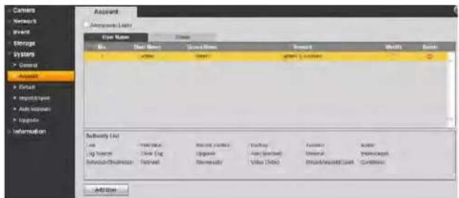
To create a user account:
-
Click Add User.
-
Configure the following:
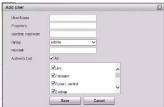
- User Name: Enter a user name for the user. The user name can be up to 15 characters including letters, numbers, and underscores.
- Password: Enter a password for the user account.
- Group: Assign the user account to a group. The user account will inherit permissions from the group, which will be updated under Authority List.
- Remark: (Optional) Enter a description for the user account.
• Authority List: Use the checkboxes to assign permissions to the user account.
3. Click Save.
To create a user group:
- Click the Group ta b.
2. Click Add Group.
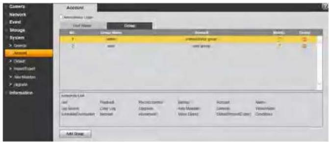
3. Configure the following:

- Group: Enter a name for the group.
- Remark: (Optional) Enter a description for the group.
- Authority List: Use the checkboxes to assign the default permissions for user accounts added to this group.
4. Click Save.
To modify a user account or group:
- Select the User or Group tab.
- Click next to the account or group you would like to delete.

- Edit the account or group details and then click Save.
To delete a user account or group:
-
Select the User or Group tab.
-
Click next to the account or group you would like to delete.

- Click OK.
Default
Click the Default button and then click OK to reset the camera to default settings. The camera will reboot.

Import/Export
The Import/Export menu allows you to export your camera's configuration or import a saved configuration.

To export the camera's configuration:
-
Click Expo rt.
-
Select a location on your computer and then click Sav e.
To import the camera's configuration:
-
Click Impo rt.
-
Select the configuration file you would like to backup and then click Open.
Auto Maintain
The Auto Maintain menu allows you to reboot the camera manually or on a automatic schedule. Rebooting the camera regularly ensures system stability. It also allows you to automatically delete old video files.
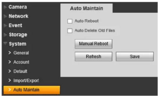
To manually reboot the camera:
- Click Manual Reboot and then click OK to reboot the camera.
To configure auto reboot:
- Check Auto Reboot to set the camera to reboot automatically on schedule.
- Select the day and time for the camera to reboot.
- Click Sav e.
To configure auto delete:
- Check Auto Del ete Old Files.
- Enter the number of days the camera will retain video files.
- Click Sav e.
Upgrade
The Upgrade menu allows you to upgrade the camera firmware. When firmware upgrades are released, they are available for free from www.digimerge.com.
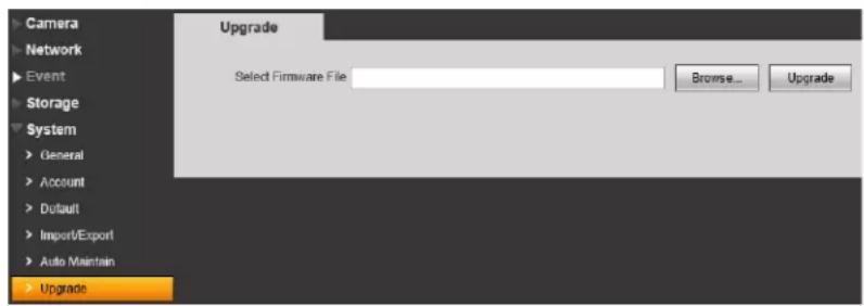
To upgrade the camera firmware:
- Download and extract the firmware from www.digimerge.com.
- Click Br owse.
- Select the firmware file on your computer and then click Open.
- Click Upgr ade. The camera will upgrade the firmware and then reboot.
Information

Version
The Version menu shows you information related to the product and firmware version.

Log
The Log menu allows you to view system logs for the camera.
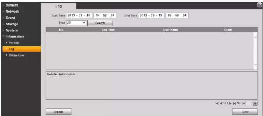
To view system logs:
-
Under St art Time and End Time, enter the start time and end time for your search.
-
Under Type, select the type of log you would like to search for: All, Setting, Data, Event, Record, Account, and Clear Log.
-
Click Sear ch.
-
(Optional) Click Backup to save logs to your computer hard drive.
- (Optional) Click Clear to delete all system logs.
Playback (Cameras with microSD Only)
Playback mode allows you to playback video from the camera's microSD card.
To playback video from the microSD card:
- Use the calendar to select a day to search for video. The bar on the bottom populates with video recorded on that day.
- Click in the time bar to start playback.

OR
- Click in the calendar to select a day to search for video.
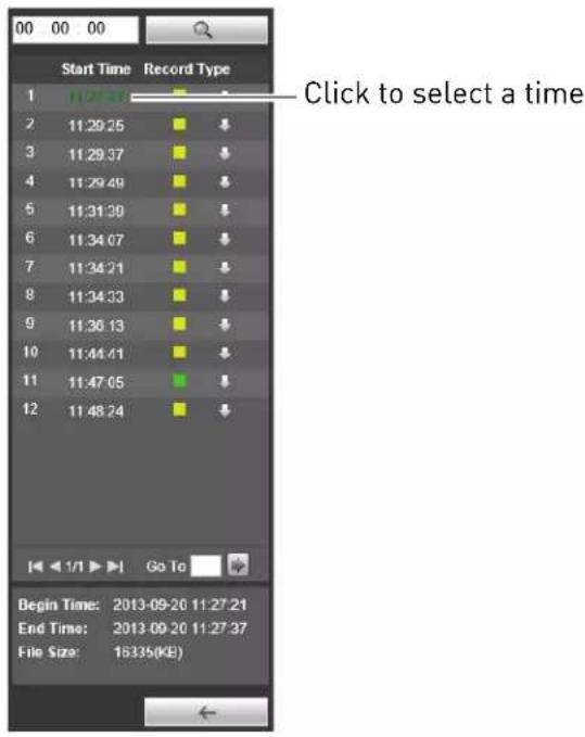
- Click ☐. A list appears with video files from the selected day.
- Click a time to select it.
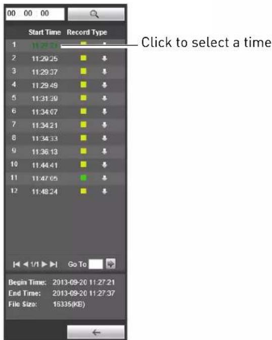
- Click then to start playback.
Playback Controls
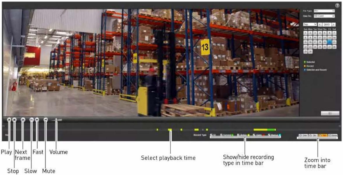
Backing up Video Files
You can download video files to your computer hard drive. Video files are saved in (.dav) format. You can use the video player available from www.digimerge.com to play backup video files.
To backup video files:
-
Click in the calendar to select a day to search for video.
-
Click ☐. A list appears with video files from the selected day.
-
Click ↓ next to the video file you would like to download to your computer hard drive.
UPGRADE TOOL
To perform a firmware upgrade over the LAN or Internet, a Config Tool is provided on the CD or www.digimerge.com. In an effort to continuously improve the functionality of our products, firmware upgrades are available as a free download on www.digimerge.com.
NOTE: The Config Tool is supported on PC only. Firmware upgrades can also be completed using the web browser interface (see "Upgrade" on page 33).
Installing a Firmware Upgrade Over the LAN
Prerequisites:
- Connect your IP camera to a router or switch on your network.
- Download a firmware upgrade from www.digimerge.com, if one is available. Extract the contents.
To perform a firmware upgrade over the LAN:
- Download the Config Tool from www.d igimerge.com.
- Extract the contents into a folder.
- Open the folder and right-click ConfigTool.exe and Run as administrator. If a Windows Firewall warning appears, click Allow Access. The Config Tool scans your LAN for IP cameras.
- Click Upgrade.
![Device List IP | IP Address | Port | Sub-port Mask | Default: 0% | Port Address | Device | Map 1 10.0.0.19 35000 225.225.225.0 10.0.0.1 90.02 at 8c:7.1b WTR-7 109 2 2001 6d:207:9403/84 35000 2001.bail 2 90.02 at 8c:7.1b WTR-7 109 Click Upgrade Up to: You can click "Login" button directly and the port corresponding information to login. IP Version [A1] Upgrade Refresh Login Layout](/content/2026/05/952424/images/8e36aed967a10ac27968e204af3bf58633930d076dcc720a15710f136a95044e.jpg)
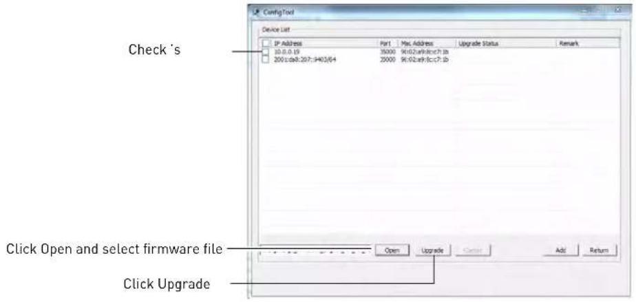
- Check any IP cameras you would like to upgrade.
-
Click Open. Select the upgrade firmware file (.bin).
-
Click Upgrade. Wait for the upgrade to complete. Do not power off the system or disconnect the power cable during upgrade. The system will restart when the upgrade is complete.
Installing a Firmware Upgrade Over the Internet
Prerequisites:
- Port forward the Client Port (default: 35000) on the IP camera's local router.
- Obtain the public IP address of the IP camera.
- Download a firmware upgrade from www.digimerge.com, if one is available. Extract the contents.
To perform a firmware upgrade over the Internet:
- Download the Config Tool from www.d igimerge.com.
- Extract the contents into a folder.
- Open the folder and right-click ConfigTool.exe and Run as administrator.
- Click Login.
- Under IP Address, enter the public IP address of the IP camera. Edit the User Name, Password, or Port if these have been changed from the default values.

- Click Login. The Config Tool logs in to the IP camera.
- Click Syst em Upgrade.
-
Click Open. select the firmware file (.bin).
-
Click Upgrade. Wait for the upgrade to complete. Do not power off the system or disconnect the power cable during upgrade. The system will restart when the upgrade is complete.

FLIR SYNCROIP CENTRAL MANAGEMENT SOFTWARE FOR PC
FLIR SyncrolP CMS is a central management software that allows you to view and manage multiple s and IP cameras.

System Requirements
Your system must meet or exceed the system requirements below:
DescriptionRequirement
CPU Core 2 Duo 3.0GHz
Operating System Windows™ 8/7/Vista
Memory 2GB
Video 512 MB of video memory and above
Network (LAN) 10/100 BaseT Network
Network (WAN) 1 Mbps upstream
*High-speed Internet service is required to remotely connect to your system.
NOTE: To connect to your system on Mac, please visit www.digimerge.com for instructions.
Installing FLIR SyncroIP CMS
Install FLIR SyncroIP CMS from the CD included with your IP camera or by downloading it from www.digimerge.com. It is recommended to visit www.digimerge.com for the latest software versions.
To start the software:
- Double-click the FLIR SyncrolP CMS icon [] FLIR the desktop.
- Click Login.
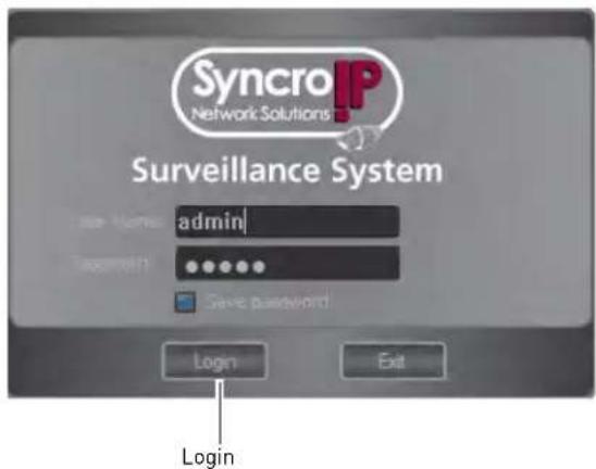
NOTE: The CMS default User Name is admin and the Password is admin.
Adding an IP camera from the Local Area Network (LAN)
Once you open the software, you can add an IP camera.
Prerequisites:
- Connect the IP camera to a router or switch on the network.
• Install the CMS on a computer in the same LAN as the IP camera.
To add a :
- Click Config Manager→Devic e Manage.
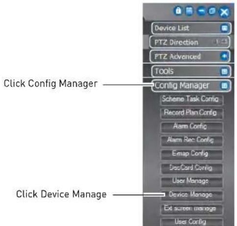
- Click Search Device. If a Windows Firewall alert appears, click Allow.
- Check the IP camera and click Add Management.

- Enter the User Name (default: admin) and Password (default: admin) for the IP camera and click OK.

- Click OK.
-
Click Devic e List.
-
Click + next to No Group.
- Double-click the IP camera.
- Click-and-drag the IP camera to the display area to view.

Adding an IP camera using a DDNS address
If you have IP camera systems with DDNS set up, you can add them to the CMS.
Prerequisites:
- Create a DDNS account. For details, see the Quick Network Guide provided with your camera or see "DDNS" on page 16.
- Enter the DDNS information into the IP camera locally.
- Port forward the Client and HTTP ports (default, ports 80 and 35000) on the router.
To add an IP camera using a DDNS address:
- Click Config Manager→De vice Manage.

2. Click Manual Add.
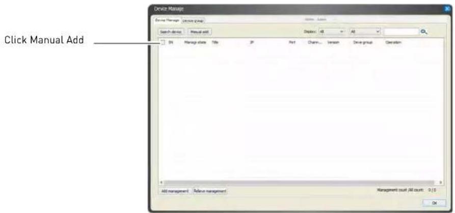
3. Configure the following:
- Title: Enter a name for your IP camera of your choice (e.g. home or office).
- Type: Select IP Camera.
- Add Type: Select Single Device.
- Domain Name: Enter the Domain Name from the confirmation email after your registered for DDNS, followed by .myddns-flir.com.
- Port: Enter the Client Port (default: 35000).
- User: Enter the IP camera's user name (default: admin).
- Password: Enter the IP camera's password (default: admin).

- Click Ad d, then click OK.
- Click Devic e List.
- Click + next to No Group.
-
Double-click the IP camera.
-
Click-and-drag the IP camera to the display area to view.

CMS Live Viewing Overview

- Camera Controls:

2. Live View Toolbar:

-
CMS Quick Menus: Click to access key CMS functions.
-
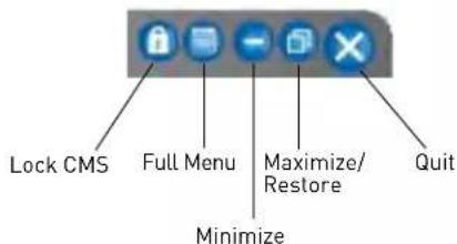
CMS Window Controls:
-
Device List: Open's and IP cameras in live display.
-
Click + next to 's, Groups, or IP cameras to expand.
- Click and drag 's, Groups, or IP cameras to the display area to open.
-
Right-click 's, Groups, or IP cameras to view system options.
-
CMS Menus:
• PTZ Direction: Access basic PTZ controls.
• PTZ Advanced: Access advanced PTZ controls (e.g. Auto Scan, Tour, etc.).
- Tools: Contains the following menus: Begin Record Plan, NVD Control, Health Report, Log Search, Alarm Video, Alarm Output, Color Config, Volume.
- Config Manager: Contains the following menus: Scheme Task Config, Record Plan Config, Alarm Config, Alarm Rec Config, E-Map Config, DecCard Config, User Manage, Device Manage, Ext Screen Manage, User Config.
Configuring Projects

Once you have multiple tasks set up, you can configure projects to automatically cycle through them.
To configure a project:
- Click Config Manager→Scheme T ask Config.
2. Click Monitor Project.
Click Monitor Project

- Click New.
- Enter a Name for the project. You may not change the name after the project is created.
- Under Mode, select Tour Mode or Schedule Mode. Tour Mode will cycle through tasks on a fixed interval. Schedule Mode will switch tasks at a pre-defined time of the day.

-
Under Task Name, select the task you would like to add to the project.
-
If you selected Tour Mode, enter the Interval Time in minutes that the task will run for before changing to the next task.
-
If you selected Schedule Mode, enter the time of day when the task will start running.
-
Click Add.
- Repeat steps 6-7 for each additional task you would like to add to the project.
- Click OK. Click k OK to save changes.
Running Tasks and Projects
- Once you have configured tasks or projects, you may run them by clicking Task ( ) and then selecting the task or project you would like to run.
- You may also select a task or project to run when you first launch the CMS. For details, see "Configuring CMS Options" on page 51.
Using E-Map
The E-Map feature allows you to visually map your cameras over a .jpg image.
Configuring E-Map
Use the steps below to select a .jpg image to use for the E-Map and place your cameras.
To configure the E-Map:
-
Click Config Manager→E-Map Config.
-
Click Picture Edit.
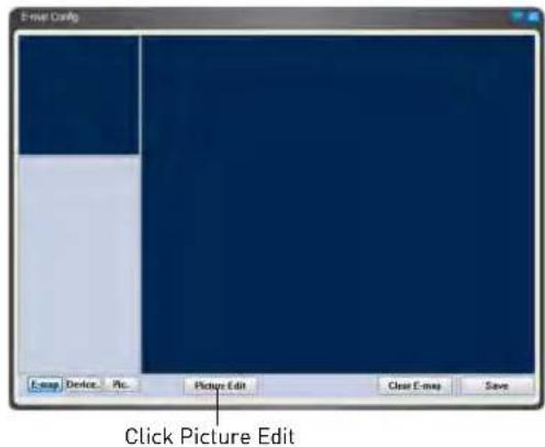
- Click Add.

-
Click Browse. Select a .jpg image on your computer to use as the E-Map.
-
Enter a Name and Title for your E-Map of your choice.
Click Browse to select a .jpg image

- Click OK.
7. Click Pic.

- Click-and-drag the picture to the window to use it for the E-Map.
- Click Device t o view a list of connected s and IP cameras.
- Click + next to an or IP camera. To place cameras, drag cameras from the list to the map.

11. Click Save.
NOTE: To delete all E-Map data, including images and camera positions, click Clear E-Map.
Opening Cameras from E-Map
Once you have configured your E-Map, you can use it to open cameras in live display.
To open cameras from E-Map:
1. Click E-Ma p (

- Click on a display area in the main CMS window, then double-click on the camera to open it.

Configuring the CMS
You can configure settings for the CMS such as the admin password, recording directories, and start up settings through the Config menu.
Configuring CMS Options
- Click Config()→Options.
- Configure the following:

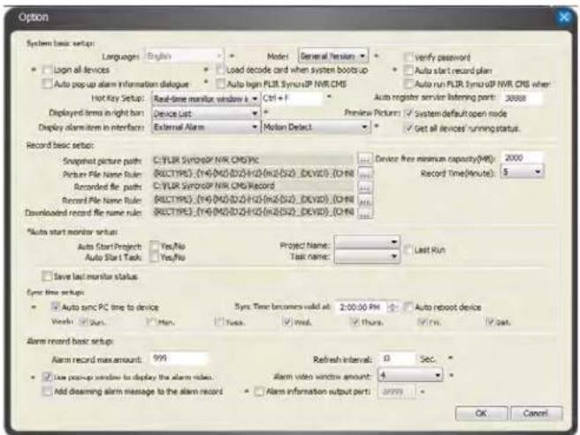
- Verify password: Check to require passwords when logging into or closing the CMS.
- Log in all devices: Check to allow the CMS to log into all s and IP cameras when it opens.
-
Auto start record plan: Check to have the CMS automatically start the record plan, which allows recording to the computer hard drive when it opens. To configure the record plan, click Config Manager→Record Plan Config.
-
Auto Login FLIR SyncrolP CMS: Check for the CMS to automatically log in the admin account when it is opened.
- Hotkey Setup: Configure hotkeys for the CMS. Use the drop-down menu to select the command, and then click inside the box on the right and enter the hotkey.
NOTE: Do not use F12 as a hotkey. F12 is reserved for the system debug command.
- Displayed items in the right bar: Select which right-side menu is opened when the CMS opens.
- Record Time (M): Select the length in minutes of video files recorded on your computer hard drive. For example, if you select 15 minutes, the system will save a new video file for every 15 minutes of recording.
- Snapshot picture path: Click ... to select the default save folder for snapshots.
- Picture file name rule: Click ... to define the file name rule for snapshots.
- Recorded file path: Click ... to select the default save folder for manual recordings.
- Recorded file name rule: Click ... to select the file name rule for manual recordings.
- Downloaded file path: Click ... to select the folder for downloaded recording files.
- Download record file name rule: Click ... to define the file name rule for downloaded recording files.
- Device free minimum space (MB): Enter the amount of minimum space in MB to maintain on the computer hard drive. The system will stop recording when only this much space is left.
- Auto Start Project: Check for the CMS to automatically run a project when opened. Select the project it will run under Project Name.
- Auto Start Task: Check for the CMS to automatically run a task when opened. Select the task it will run under Task Name.
- Last Run: Check for the CMS to start the last used task or project when opened.
- Save last monitor status: Check to have the CMS restore the previously used display mode when opened.
- Auto sync PC time to device: Check to have the s and IP cameras sync the clock with the system time on the PC.
- Sync time becomes valid at: Select the time that s or IP cameras will sync their clocks with the PC's system time.
- Week: Select days that s or IP cameras will sync their clocks with the PC's system time.
- Auto reboot device: Check to enable s or IP cameras to reboot when the time sync occurs.
- Click 0k to save changes. Close the CMS and restart it to update the configuration.
Changing the CMS Admin Password
You can change the admin password that is used to log into the CMS. The default password is admin.
NOTE: The CMS will automatically populate the admin password unless you enable Verify Password under Config→Options.
To change the CMS admin password:
- When logged in as the admin account, click Config(
)→Modify Password. - Under Old P password, enter the old password.
- Under New P password and Confirm Password, enter the new password.


4. Click OK.
Adding User Accounts to the CMS
You can create multiple user accounts for the CMS with varying levels of access to the system. These user accounts are only used for access to the CMS software and are separate from the passwords on the or IP camera systems.
NOTE: To make sure users must enter their user name and password to access the CMS, you must make sure Verify User is checked and Auto Login is unchecked in Config→Options. For details, see "Configuring CMS Options" on page 51.
To add a user account to the CMS:
-
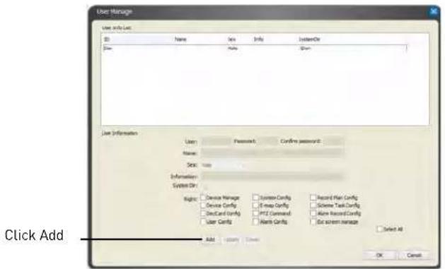
Click Config Manager→User Manage.
-
Click Add.
-
Configure the following:
-
User: Enter the user name for the account.
- Password/Confirm: Enter the password for the account.
- Name/Sex/Information: (Optional) Enter descriptive details about the user account.
-
Right: Check the permissions that will apply to the user account.
-
Click Save. Click OK to save changes.
Multi-Monitor Support
The CMS supports up to 4 monitors on a single system. The recommended system specifications are listed below. If your system does not meet the requirements below, you may experience slow system performance.
Minimum system recommendations to run the CMS on multiple monitors:
- Intel Core i5 or i7 processor.
- 6 GB of RAM.
- Geforce 9500GT video card, 1GB or greater.
Opening Cameras in Secondary Monitors
- To open a single channel on a secondary monitor: Open it in a window on the main screen, then right-click on the display area, and select Output current window to extension screen. Select the monitor you would like to send the channel to.
- To open multiple-channels on a secondary monitor: Open your desired channel view, then right click in the display area, and select Output all windows to extension screen. Select the monitor you would like to send them to.
![[Pir MV5] © Kape 5 Talk Audio Format Output current window to the extension screen Output all windows to the extension screen Copy Video info Close current window video Close Videos of all windows Video Attribute Right-click and select output option to open channels on a secondary monitor](/content/2026/05/952424/images/8ac18fbece3c44c50cd8448425fff2bdc66526db7af6195325259f07dd574e33.jpg)
Managing Secondary Monitors
Use Ext Monitor Config to configure settings for secondary monitors. You can select which monitors you would like to enable. Enabled monitors start up when you open the CMS software.
You can close secondary monitors by clicking on them and then pressing ESC. However, you must close the CMS software and restart it to re-open windows on secondary monitors.
To manage secondary monitors:
-
Click Config Manager→Ext Screen Manager.
-
Click Search to detect secondary monitors or Identify to display the monitor number assigned to each secondary monitor.

- Check monitors to open them when the CMS software opens or uncheck to disable.
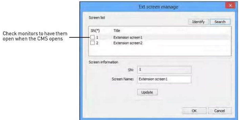
- Click OK to save changes. Restart the CMS software to open the new monitor configuration.
SMARTPHONE AND TABLET APPS
iPhone
FLIR SyncrolP NVR is an iPhone app that allows you to remotely view your IP camera.
System Requirements
- iOS 4.3 or later.
Prerequisites
- Port 80 and 35000 (or your HTTP and Client Ports, if you have changed them) must be port forwarded on your router to your camera's IP address.
- You must create a DDNS account, and have the DDNS settings configured in your IP camera.
- The IP camera must have Internet access.
- You must have a DDNS address to log in remotely.
- An iTunes account.
NOTE: You will need to create an iTunes account before you can download the app. An iTunes store account requires a valid credit card number. The app is free of charge.
Connecting to your IP camera on an iPhone
- Download FLIR SyncrolP NVR for free from the App Store.
- Tap on the FLIR SyncroIP NVR icon ( [icon] ) to start the app.
- Tap
- Tap Device Manager.

Device Manager
5. Tap Add→Manually Add.

6. Configure the following:
- Name: Enter a name for your IP camera of your choice.
- Address: Enter your DDNS address (e.g. tomsmith.myddns-flir.com).
- Port: Enter the Client Port (default: 35000).
- Username: Enter the IP camera's User Name (default: admin).
- Password: Enter the IP camera's Password (default: admin).
- Channel: Enter 1.

7. Tap Save.
8. Tap
9. Tap Live Preview.
- Tap + on one of the display areas and select the camera to open it in the selected display area.

FLIR SyncrolP NVR Interface
You can use FLIR SyncrolP NVR in portrait and landscape mode.

Viewing Videos with Local File
If you have saved videos using FLIR SyncrolP, you may open them with Local File.
NOTE: You may open screenshots using the Photos app.
To access Local File:
• From the Main Menu, tap Local File.

Using Playback Mode on iPhone
You can access recorded video on your IP camera's microSD card using your iPhone.
NOTE: You must configure your camera to record the sub stream to use playback mode on mobile devices. For details, see "Record Control" on page 28.
To use Playback Mode:
- From the Main Menu, tap Playback.
NOTE: If Playback is not shown, tap Add, check Playback, and return to the Main Menu.
- Tap +.

-
Select the start and end times to playback.
-
Select a camera to playback.

- Use the on-screen controls to control playback.
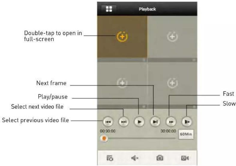
Enabling Push Notifications
You can have the app send push notifications to the notifications area on your device when the camera detects motion. Once you have received a push notification, you can select it to open live video from the camera.

NOTE: Motion detection must be activated to receive push notifications. For details on enabling motion detection, see "Video Detect" on page 19.
NOTE: Your camera must be configured to record the sub-stream to open video from push notifications. For details on configuring sub-stream recording, see "Record Control" on page 28.
To enable Push Notifications:
- From the Main menu, tap Push Config.
NOTE: If Push Config is not shown, tap Add, check Push Config, and then return to the Main Menu.
- For the IP camera you would like to configure, set the slider to ON.

- Tap Motion Detect and then check CAM 1.

- Tap OK. A test notification will be sent to your device. After this, whenever the selected cameras detect motion, you will receive a notification.
Device Manager
You can use Device List to manage your IP cameras and NVRs.
To access Device List:
• From the Main Menu, tap Device Manager.
To edit a device:
- Tap the device in Device Manager.
- Edit the connection details as needed.
- Tap Save.
To delete a device:
- Swipe right on the device you would like to delete.
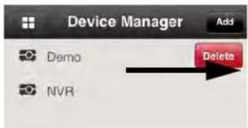
Swipe right on the device you would like to delete and tap delete
- Tap Delete. Tap OK to confirm.
iPad
FLIR SyncrolP NVR HD is an iPad app that allows you to remotely view your IP camera.
System Requirements
- iOS 4.3 or later.
Prerequisites
- Port 80 and 35000 (or your HTTP and Client Ports, if you have changed them) must be port forwarded on your router to your camera's IP address.
- You must create a DDNS account, and have the DDNS settings configured in your IP camera.
• The IP camera must have Internet access.
- You must have a DDNS address to log in remotely.
- You will need to create an iTunes account before you can download the app. An iTunes store account requires a valid credit card number. The app is free of charge.
Connecting to your IP camera on an iPad
-
Install FLIR SyncrolP NVR HD for free from the App Store.
-
Tap on the FLIR Syncro IP NVR HD icon ( ) to start the app.
-
Tap

then

- Tap Device Manager.
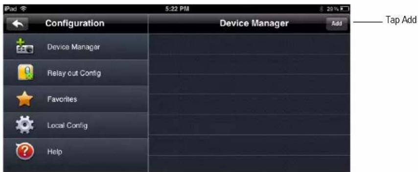
- Tap Add.
6. Configure the following:

- Name: Enter a name for your IP camera of your choice.
- Address: Enter your DDNS address (e.g. tomsmith.myddns-flir.com).
- Port: Enter the Client Port (default: 35000).
- Username: Enter the IP camera's User Name (default: admin).
- Password: Enter the IP camera's Password (default: admin).
• Channel amount: Enter 1.
7. Tap Save.
8. Tap
- In landscape mode: tap a channel and then select the camera you would like to view on the left.
OR
In portrait mode: tap + on one of the display areas and select the camera you would like to open.

FLIR SyncrolP NVR HD Interface
You can use FLIR SyncrolP NVR HD in landscape or portrait mode.

Device Manager
Device Manager allows you to manage your IP cameras and NVRs.
To access Device Manager:
- From live view, tap
then - Tap Device Manager.


To delete a device:
-
Tap the device to select it.
-
Tap ☐. Tap Yes to confirm.

To modify a device:
- Tap a device to select.
- Tap the device again to open the edit screen.
- Update the connection details as needed and then ta p Save.
Using Playback Mode on iPad
You can access recorded video on your IP camera using your iPad.
NOTE: You must configure your camera to record the sub stream to use playback mode on mobile devices. For details, see "Record Control" on page 28.
To use Playback Mode:
- From Live View tap

then

- In Portrait Mode: Ta p+, select the start time and end time for your search, and select the camera you would like to playback.
OR
In Landscape Mode: Select the start time and end time for your search, and select the camera you would like to playback.

- Use the playback controls.

NOTE: Playback controls are only shown in portrait mode.
Enabling Push Notifications
You can have the app send push notifications to the notifications area on your device when the camera detects motion. Once you have received a push notification, you can select it to open live video from the camera that detected motion.

NOTE: Motion detection must be activated to receive push notifications. For details on enabling motion detection, see "Video Detect" on page 19.
NOTE: Your camera must be configured to record the sub-stream to open video from push notifications. For details on configuring sub-stream recording, see "Record Control" on page 28.
To enable Push Notifications:
- From live view, tap

then

-
Tap Alarm Push.
-
Set the slider to ON next to the IP camera you would like to configure.

- Tap Motion Detect then check CAM 1.

- Tap OK. A test notification will be sent to your device. After this, whenever the selected cameras detect motion, you will receive a notification.
NOTE: You can see a list of notifications through the Event List menu. To show the Event List

Android Phones
FLIR SyncrolP NVR allows you to remotely view your IP camera on Android smartphones.
A separate app is available to remotely view your IP camera on Android tablets, to make better use of the larger screen size. For details, see "Android Tablets" on page 73.
Compatible Devices
- Android OS (2.2 and above).
Prerequisites
- Port 80 and 35000 (or your HTTP and Client Ports, if you have changed them) must be port forwarded on your router to your camera's IP address.
- You must create a DDNS account, and have the DDNS settings configured in your IP camera.
- The IP camera must have Internet access.
- You must have a DDNS address to log in remotely.
Connecting to your IP Camera on an Android Phone
- Download FLIR SyncrolP NVR for free from the Google Play Store.
- Tap on the FLIR SyncroIP NVR icon ( ) to start the app.
- Tap
4. Tap Device Manager.

5. Tap Add→Manually Add.

6. Configure the following:
- Name: Enter a name for your IP camera of your choice.
- Address: Enter your DDNS address (e.g. tomsmith.myddns-flir.com).
- Port: Enter the Client Port (default: 35000).
- Username: Enter the IP camera's User Name (default: admin).
- Password: Enter the IP camera's Password (default: admin).
- Channel: Enter 1.
7. Tap Save.
8. Tap

9. Tap Live Preview.

- Tap + on one of the display areas and select the camera you would like to open in the selected display area.
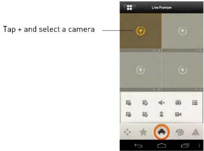
- Repeat to view additional cameras.
FLIR SyncrolP NVR Interface
You can use FLIR SyncrolP NVR in portrait and landscape mode.

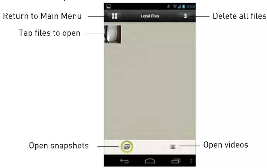
Viewing Snapshots and Videos with Local Files
If you have saved snapshots or videos using FLIR SyncroIP NVR, you may open them with Local Files.
To access Local Files:
- From the Main Menu, tap Local Files.
Using Playback Mode on Android Phones
You can access recorded video on your IP camera using your Android phone.
NOTE: You must configure your camera to record the sub stream to use playback mode on mobile devices. For details, see "Record Control" on page 28.
To use Playback Mode:
- From the Main Menu, tap Playback.
-
If Playback is not shown, tap Add, check Playback, and return to the Main Menu.
-
Tap + and select a camera to playback.
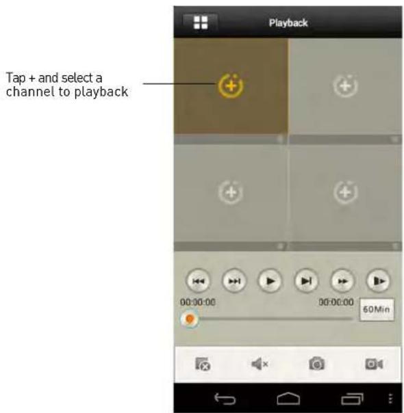
- Select the date then the start and end times to playback.
- Use the on-screen controls to control playback.

Enabling Push Notifications
You can have the app send push notifications to the notifications area on your device when one of your cameras detects motion. Once you have received a push notification, you can select it to open
live video from the camera that detected motion.

NOTE: Motion detection must be activated to receive push notifications. For details on enabling motion detection, see "Video Detect" on page 19.
NOTE: Your camera must be configured to record the sub-stream to open video from push notifications. For details on configuring sub-stream recording, see "Record Control" on page 28.
To enable Push Notifications:
- From the Main menu, tap Push Config.
NOTE: If Push Config is not shown, tap Add, check Push Config, and then return to the Main Menu.
- Tap the IP camera you would like to configure.

- Tap Motion Detect and then check CAM 1.

- Tap OK. A test notification will be sent to your device. After this, whenever the selected cameras detect motion, you will receive a notification.
Device Manager
You can use Device List to manage your IP cameras and NVRs.
To access Device List:
- From the Main Menu, tap Device Manager.
To edit a device:
- Tap the device in Device Manager.
-
Edit the connection details as needed.
-
Tap Save.
To delete a device:
- Swipe the device you would like to delete to the right.
- Tap Del ete. Tap OK to confirm.

Android Tablets
FLIR SyncrolP NVR HD is an app that allows you to remotely view your IP camera on an Android tablet.
System Requirements
- Android 3.3 or later.
Prerequisites
- Port 80 and 35000 (or your HTTP and Client Ports, if you have changed them) must be port forwarded on your router to your camera's IP address.
- You must create a DDNS account, and have the DDNS settings configured in your IP camera.
- The IP camera must have Internet access.
- You must have a DDNS address to log in remotely.
Connecting to your IP Camera on an Android Tablet
-
Install FLIR SyncrolP NVR HD for free from the Google Play Store.
-
Tap on the FLIR Syncro IP NVR HD icon ( ) to start the app.
-
Tap

4. Tap Device Manager.
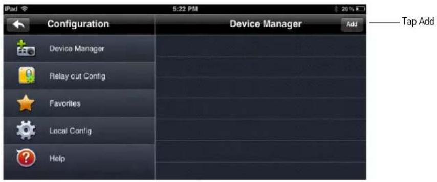
5. Tap Add.
6. Configure the following:

- Name: Enter a name for your IP camera of your choice.
- Address: Enter your DDNS address (e.g. tomsmith.myddns-flir.com).
- Port: Enter the Client Port (default: 35000).
- Username: Enter the IP camera's User Name (default: admin).
- Password: Enter the IP camera's Password (default: admin).
- Channel amount: Enter 1.
7. Tap Sav e.
8. Tap

- In landscape mode, tap a display area and then select the camera you would like to view on the left. In portrait mode, tap + on one of the display areas and select the camera you would like to open.

FLIR SyncrolP NVR HD Interface
You can use FLIR SyncrolP NVR HD in landscape or portrait mode.

Using Playback Mode on Android Tablets
You can access recorded video on your IP camera using your Android tablet.
NOTE: You must configure your camera to record the sub stream to use playback mode on mobile devices. For details, see "Record Control" on page 28.
To use Playback Mode:
- From Live View tap

then

- In Portrait Mode: Ta p+, select the start time and end time for your search, and select the camera you would like to playback.
OR
In Landscape Mode: Select the start time and end time for your search, and select the camera you would like to playback.

- Use the playback controls.
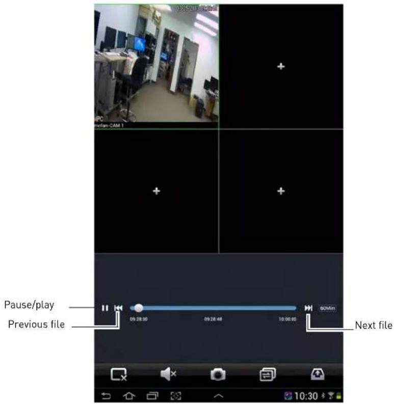
NOTE: Playback controls are only shown in portrait mode.
Enabling Push Notifications
You can have the app send push notifications to the notifications area on your device when the camera detects motion. Once you have received a push notification, you can select it to open live video from the camera.
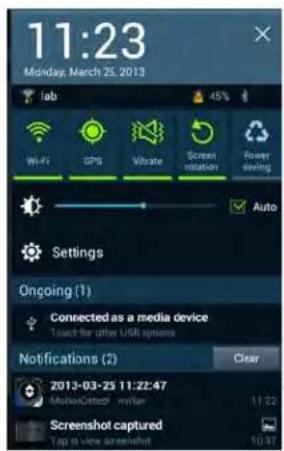
Push notification
NOTE: Appearance of notifications may differ depending on the model of your device
NOTE: Motion detection must be activated to receive push notifications. For details on enabling motion detection, see "Video Detect" on page 19.
NOTE: Your camera must be configured to record the sub-stream to open video from push notifications. For details on configuring sub-stream recording, see "Record Control" on page 28.
To enable Push Notifications:
- From live view, tap

then

- Tap Alarm Push.
- Select the IP camera you would like to configure.

4. Tap MotionDetect then check CAM 1.
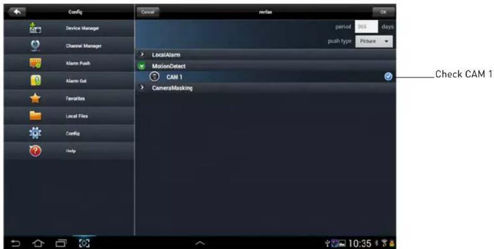
- Tap OK. A test notification will be sent to your device. After this, whenever the selected cameras detect motion, you will receive a notification.
NOTE: You can see a list of notifications through the Event List menu. To show the Event List
menu, from live view, tap then

Device Manager
Device Manager allows you to manage your IP cameras and NVRs.
To access Device Manager:
- From live view, tap

then

- Tap Device Manager.
To delete a device:
-
Tap the device to select it.
-
Tap . Tap OK to confirm.

To modify a device:
- Tap a device to select.
- Tap the device again to open the edit screen.
- Update the connection details as needed and then t ap Save.
Need Help?
Please make sure to visit our website www.digimerge.com to receive product updates and information.
3 Easy Ways To Contact Us

natural_image
Woman in orange top using a laptop with a glass of juice, sitting on a bed (no visible text or symbols)
natural_image
Elderly couple sitting together, one using a laptop (no visible text or symbols)
natural_image
Man in lab coat talking on phone in a laboratory setting (no visible text or symbols)Online:
Product support is available 24/7 including product information, user manuals, quick start up guides and FAQ's at www.digimerge.com
By Email:
Technical support (for technical/installation issues) tech@digimerge.com
By Phone:
North America: 1-866-816-5919 Technical support (for technical/installation issues) Mon-Fri 8.00 am to 8.00pm EST
We welcome your feedback at info@digimerge.com
For more information, visit www.digimerge.com


- SyncrolP Series IP Cameras
- Software Manual
- Instruction Manual
- TABLE OF CONTENTS
- Overview 1
- Web Configuration Interface 2
- Setup 9
- iPad 62
- Android Phones 67
- Android Tablets 73
- OVERVIEW
- Notes
- WEB CONFIGURATION INTERFACE
- Supported Browsers
- Internet Explorer Setup
- Safari Setup
- Live View
- Video Display Controls
- Menu Tabs
- Live View Functions
- PTZ Controls (PTZ Cameras Only)
- PTZ Control Panel
- Scan
- To configure scan function:
- Preset
- To save presets:
- To go to a preset:
- To delete presets:
- Pattern
- To save a pattern:
- To run a pattern:
- Goto
- To move the camera to a specified position:
- Setup
- Camera
- Conditions
- To configure the image sensor settings:
- Profile Management
- To configure the condition profile:
- Click Save to save changes.
- Zoom and Focus (Motorized Lens Cameras Only)
- Video
- To configure video quality settings:
- Snapshot
- To configure snapshots:
- Overlay
- To configure the OSD:
- Path
- To configure the recording and snapshot folder:
- Network
- TCP-IP
- Connection
- To configure connection settings and ports:
- PPPoE (Unsupported)
- DDNS
- To configure DDNS:
- IP Filter
- To filter connections based on IP or MAC addresses:
- SMTP (Email)
- To configure SMTP Settings:
- UPnP
- Bonjour
- To enable / disable the Bonjour service:
- To access the camera through Bonjour:
- SNMP (Unsupported)
- Multicast (Unsupported)
- IEEE802 (Unsupported)
- QOS (Unsupported)
- Event
- Video Detect
- To set up motion detection settings:
- Video Masking (Unsupported)
- Alarm (Cameras with Alarm I/O Only)
- Configure the following:
- Click Sav e to save changes.
- Warning
- No SD Card
- To configure No SD Card errors:
- Capacity Warning
- To configure Capacity Warnings:
- SD Card Error
- To configure SD Card Errors:
- Disconnection
- To configure Disconnection Errors:
- IP Conflict
- To configure IP Conflict errors:
- Storage
- Record Schedule
- To configure the recording schedule:
- Snapshot Schedule
- To configure the snapshot schedule:
- Holiday Schedule
- To configure the holiday schedule:
- Destination - Path
- Destination - Local
- Destination - FTP
- To set up FTP settings:
- Record Control
- To configure recording parameters:
- System
- General
- To configure general camera settings:
- General - Date & Time
- To configure date & time settings:
- Account
- To create a user account:
- Click Save.
- To create a user group:
- Click Add Group.
- Configure the following:
- Click Save.
- To modify a user account or group:
- To delete a user account or group:
- Default
- Import/Export
- To export the camera's configuration:
- To import the camera's configuration:
- Auto Maintain
- To manually reboot the camera:
- To configure auto reboot:
- To configure auto delete:
- Upgrade
- To upgrade the camera firmware:
- Information
- Version
- Log
- To view system logs:
- Playback (Cameras with microSD Only)
- To playback video from the microSD card:
- OR
- Playback Controls
- Backing up Video Files
- To backup video files:
- UPGRADE TOOL
- Installing a Firmware Upgrade Over the LAN
- Prerequisites:
- To perform a firmware upgrade over the LAN:
- Installing a Firmware Upgrade Over the Internet
- To perform a firmware upgrade over the Internet:
- FLIR SYNCROIP CENTRAL MANAGEMENT SOFTWARE FOR PC
- System Requirements
- DescriptionRequirement
- Installing FLIR SyncroIP CMS
- To start the software:
- Adding an IP camera from the Local Area Network (LAN)
- To add a :
- Adding an IP camera using a DDNS address
- To add an IP camera using a DDNS address:
- Click Manual Add.
- Live View Toolbar:
- Configuring Projects
- To configure a project:
- Click Monitor Project.
- Running Tasks and Projects
- Using E-Map
- Configuring E-Map
- To configure the E-Map:
- Click Pic.
- Click Save.
- Opening Cameras from E-Map
- To open cameras from E-Map:
- Click E-Ma p (
- Configuring the CMS
- Configuring CMS Options
- Changing the CMS Admin Password
- To change the CMS admin password:
- Click OK.
- Adding User Accounts to the CMS
- To add a user account to the CMS:
- Multi-Monitor Support
- Opening Cameras in Secondary Monitors
- Managing Secondary Monitors
- To manage secondary monitors:
- SMARTPHONE AND TABLET APPS
- iPhone
- Prerequisites
- Connecting to your IP camera on an iPhone
- Tap Add→Manually Add.
- Configure the following:
- Tap Save.
- Tap
- Tap Live Preview.
- FLIR SyncrolP NVR Interface
- Viewing Videos with Local File
- To access Local File:
- Using Playback Mode on iPhone
- To use Playback Mode:
- Enabling Push Notifications
- To enable Push Notifications:
- Device Manager
- To access Device List:
- To edit a device:
- To delete a device:
- iPad
- Connecting to your IP camera on an iPad
- FLIR SyncrolP NVR HD Interface
- To access Device Manager:
- To modify a device:
- Using Playback Mode on iPad
- Android Phones
- Compatible Devices
- Connecting to your IP Camera on an Android Phone
- Tap Device Manager.
- Viewing Snapshots and Videos with Local Files
- To access Local Files:
- Using Playback Mode on Android Phones
- Android Tablets
- Connecting to your IP Camera on an Android Tablet
- Tap Add.
- Tap Sav e.
- Using Playback Mode on Android Tablets
- Tap MotionDetect then check CAM 1.
- Need Help?
- Easy Ways To Contact Us
- Online:
- By Email:
- By Phone:
Brand : Digimerge
Model : SyncroIP DNB13TF22
Category : Security Camera