
AP300M - Wi-Fi repeater Speco Technologies - Free user manual and instructions
Find the device manual for free AP300M Speco Technologies in PDF.


| Product Type | Outdoor Network Video Bridge / Point-to-Point Access Point |
| Model | AP300M |
| Brand | Speco Technologies |
| Frequency Band | 4.96 ~ 6.065 GHz |
| Maximum Data Rate | 300 Mbps (HT40) |
| Range (Line of Sight) | Up to 7000 feet |
| Antenna Gain | 18 dBi |
| Interfaces | 2 x 10/100 Mbps LAN (RJ45) |
| Power Supply | PoE 24V 1A (included injector) |
| Power Consumption | ≤ 6W |
| Dimensions (without mount) | 7.9" diameter x 2.5" H |
| Dimensions (with mount) | 7.9" diameter x 5.2" H |
| Operating Temperature | -22°F to 149°F (-30°C to 65°C) |
| Storage Temperature | -58°F to 176°F (-50°C to 80°C) |
| Humidity (non-condensing) | ≤ 95% |
| Security | WEP 64/128-bit, WPA, WPA2, 802.1x, MAC address control |
| Management | Web, SNMP, Telnet, Serial |
| Chipset | Atheros AR9344 600 MHz |
| Memory | 64 MB DDR2 DRAM, 8 MB Flash |
| Standards | IEEE 802.11n, 802.11g, 802.11b, 802.3u, 802.3af |
| Modulation | OFDM, BPSK, QPSK, CCK, DQPSK, DBPSK |
| Protocols | CSMA/CA, TCP/IP, IPX/SPX, NetBEUI, DHCP, NDIS3/4/5 |
| DIP Switch Configuration | 32 groups for SSID and IP segment selection; point-to-multipoint support up to 4 cameras |
| Reception Angle | 30° horizontal, 60° vertical |
Frequently Asked Questions - AP300M Speco Technologies
User questions about AP300M Speco Technologies
0 question about this device. Answer the ones you know or ask your own.
Ask a new question about this device
Download the instructions for your Wi-Fi repeater in PDF format for free! Find your manual AP300M - Speco Technologies and take your electronic device back in hand. On this page are published all the documents necessary for the use of your device. AP300M by Speco Technologies.
USER MANUAL AP300M Speco Technologies
AP200M/AP300M 300Mbps, Outdoor Network Video Bridge w/DIP function
Thank you for your choice of Speco Technologies' AP200M or AP300M point-to-point AP. These units are designed and manufactured to provide an efficient way to connect from two to five networking points directly and securely at a distance of up to 7000' line of site.

INCLUDED IN PACKAGE:
(1) AP dish
• (1) Mount Assembly
• (1) PoE Power Adapter
(1) AC Cord
• (1) Package Mounting Hardware
OPERATING INSTRUCTIONS:
1) You will need two Cat5 cables for each dish to complete assembly
2) The PoE power adapter has 3 inputs. One is for the AC cord, and two are for networking. Please note the PoE adapter and power cord are not designed for outdoor use and should be used indoors only.
a. The bottom of the adapter has two RJ45 connections. O
b. Using one Cat5 cable, connect one end to "LAN" and the other end to your camera, recorder, PC, etc.
c. Use the other Cat5 cable to connect your AP dish to the POE input.
3) Antennas should be mounted level with each other, and transmission distance is greatly reduced if line of site is not clear
4) Antenna should always be mounted upright (RJ45 ports facing down) with port cover connected to ensure maximum weather resistance.
5) Both RJ45 ports (black and yellow) on antenna are LAN connections.
6) DIP switch instructions:


Toggle 1 changes the mode of the dish. UP is access point (AP) mode for use with your recorder, PC, etc.. DOWN is for use with your camera.
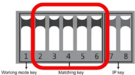
Toggles 2 through 6 are for matching AP dishes together. There are 32 various combinations that can be made from the 5 keys, which corresponds to 32 different SSIDs and 32 different segments. The chart below shows all possible combinations.
| Group | 2-6 Dial | Correspond P segment | 2.4GHz | 5.8GHz | Group | 2-6 Dial | Correspond P segment | 2.4GHz | 5.8GHz |
| [X5T] | 192,168,101,X | 2,372G | 4,96G | 17th |  | 192,168,117,X | 2,457G | 5.765G | |
| 2nd | [IXZTCI] | 192,168,102,X | 2,377G | 4,98G | 18th | 192,168,118,X | 2,462G | 5.785G | |
| 3rd | 192,168,103,X | 2,382G | 5.0G | 19th | 192,168,119,X | 2,457G | 5.805G | ||
| 4th | 192,168,104,X | 2,387G | 5.02G | 20th | 192,168,120,X | 2,472G | 5.825G | ||
| 5th | 192,168,105,X | 2,392G | 5.04G | 21st | 192,168,121,X | 2,492G | 5.845G | ||
| 6th | 192,168,106,X | 2,397G | 5.06G | 22nd | 192,168,122,X | 2,512G | 5.865G | ||
| 7th | 192,168,107,X | 2,402G | 5.08G | 23rd | 192,168,123,X | 2,532G | 5.885G | ||
| 8th | 192,168,108,X | 2,412G | 5.10G | 24th | 192,168,124,X | 2,387G | 5.905G | ||
| 9th | 192,168,109,X | 2,417G | 5.12G | 25th | 192,168,125,X | 2,392G | 5.925G | ||
| 10th | 192,168,110,X | 2,422G | 5.14G | 26th | 192,168,126,X | 2,357G | 5.945G | ||
| 11th | 192,168,111,X | 2,427G | 5.16G | 27th | 192,168,127,X | 2,352G | 5.965G | ||
| 12th | 192,168,112,X | 2,432G | 5.18G | 28th | 192,168,128,X | 2,382G | 5.985G | ||
| 13th | 192,168,113,X | 2,437G | 5.2G | 29th | 192,168,129,X | 2,392G | 6.005G | ||
| 14th | 192,168,114,X | 2,442G | 5.22G | 30th | 192,168,130,X | 2,397G | 6.025G | ||
| 15th | 192,168,115,X | 2,447G | 5.24G | 31st | 192,168,131,X | 2,512G | 6.045G | ||
| 16th | 192,168,116,X | 2,452G | 5.745G | 32nd | 192,168,132,X | 2,532G | 6.065G | ||
SPECIFICATIONS:
| Chipset Atheros AR9344 600MHz | ||||
| DRAM DDR2 64MByte | ||||
| FLASH | 8MByte | |||
| IC | SiGe5004L | |||
| Port 10/100Mbps LAN*2 | ||||
| Speed | 11a:54M,48M,36M,24M,18M,12M,9M,6Mbps | |||
| HT20:7.2M,14.4M,21.7M,28.9M,43.3M,57.8M,65M,72.2M,14.4M,28.9M,43.3M,57.8M,86.7M,115.6M,130M,144.4Mbps | ||||
| HT40:15M,30M,45M,60M,90M,120M,135M,150M,30M,60M,90M,120M,180M,240M,270M,300Mbps | ||||
| Transmission | DSSS, up to 7000' line of sight with no interference | |||
| Dimensions 7.9" Diameter x 2.5" H (5.2" High with mount attached) | ||||
| Modulation OFDM/BPSK/QPSK/CCK/DQPSK/DBPSK | ||||
| Standard IEEE802.11n,IEEE802.11g,IEEE802.11b,IEEE802.3u,IEEE802.3af | ||||
| Protocol CSMA/CA,TCP/IP,IPX/SPX,NetBEUI,DHCP,NDIS3,NDIS4,NDIS5 | ||||
| Channel | AP200M: 2.372 ~ 2.532GHz AP300M: 4.96~6.065GHz | |||
| Power dissipation | ≤6W | |||
| Power POE 24V 1A | ||||
| RF@25±2dB | 802.11a | 6-24Mbps | 27±2dB | |
| 36-48Mbps 26±2dB | ||||
| 54Mbps | 25±2dB | |||
| 802.11n | HT20 | MCS 0-3 27±2dB | ||
| MCS 4 26±2dB | ||||
| MCS 5 25.5±2dB | ||||
| MCS 6 25±2dB | ||||
| MCS 7 24.5±2dB | ||||
| HT40 | MCS 0-3 26±2dB | |||
| MCS 4 25.5±2dB | ||||
| MCS 5 25±2dB | ||||
| MCS 6 24.5±2dB | ||||
| MCS 7 24±2dB | ||||
| Sensitivity | 802.11a | 6Mbps ≤ -89; 54Mbps ≤ -73 | ||
| 802.11n | HT20 | MCS 0 ≤ -86; MCS 7 ≤ -68 | ||
| HT40 | MCS 0 ≤ -83; MCS 7 ≤ -65 | |||
| Antenna | Frequency | 4900~6100MHz | ||
| Direction Horizontal/Vertical | ||||
| Gain | 18DBi | |||
| Management | WEP management | Yes | ||
| SNMP MIB Yes | ||||
| Telnet Yes | ||||
| Serial Yes | ||||
| Security | MAC address control | Yes | ||
| Encryption WEP 64/128bits,WPA,WPA2,802.1x | ||||
| Operating conditions | Working temperature -22F~149F | |||
| Storage Temperature -58F~176F | ||||
| Humidity (non-condensed) | ≤95% (NA) | |||
Troubleshooting Tips and General Notes
1) These access points can be used in conjunction with a switch on either side of the signal. Note the bandwidth and resolution of your cameras. Each pair can typically support 6-8 1080p cameras through the switch, but if you have image quality issues such as interference, dropped images, etc., try removing cameras to see if the remaining signals improve.
2) These units operate on 24V PoE. Most surveillance-focused PoE switches operate on 48V PoE. Please use the 24V PoE injector included with the unit if you can't confirm that your PoE switch provides 24V PoE.
3) It is possible to daisy-chain pairs of antennas to extend range or get around a corner/over a hill/etc. The dishes can be connected by utilizing the extra RJ-45 connections on the dish. Please note, however, that:
a. You lose half your bandwidth each time you connect a pair
b. You must use a 4-wire CAT-5 cable (vs. the standard 8-wire) to avoid accidental transmission of additional PoE power between the antennas.
c. Please consult a trained technician or call our tech support department if you are unsure how to connect pairs of antennas.
4) Be careful about having multiple dishes on the NVR side. If they are physically close to each other and the frequencies are close together, then video meant for one dish can interfere with the other dish. To safeguard this, make sure that the two dishes that are on the NVR side are not both in the direction of the same camera dish. Also, make the frequencies as far apart as possible on the two dishes by utilizing the DIP switch chart above.
5) If connecting directly to an NVR, the access point should typically not be plugged directly into a camera port unless there is just one camera being transmitted. If an antenna is sending the signal of multiple cameras via a switch, the recorder side should be connected to the private networking port on an NVR/Hybrid.
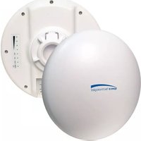
Brand : Speco Technologies
Model : AP300M
Category : Wi-Fi repeater