AirMesh MSR2000 - Router Aruba - Free user manual and instructions
Find the device manual for free AirMesh MSR2000 Aruba in PDF.


| Product Type | Wireless Mesh Router |
| Brand | Aruba |
| Model | AirMesh MSR2000 |
| Dimensions (H x W x D) | 1.75 x 17.5 x 10 inches |
| Weight | 6.5 lbs |
| Power Supply | AC 100-240V, 50-60Hz or PoE (802.3af) |
| Power Consumption | 30W max |
| Operating Frequency | 2.4 GHz and 5 GHz dual-band |
| Wireless Standards | IEEE 802.11a/b/g/n |
| MIMO Configuration | 3x3 |
| Antenna Type | External omnidirectional (included) |
| Mesh Protocol | Aruba AirMesh proprietary |
| Security Features | WPA2, WPA3, 802.1X, firewall |
| Interfaces | 2 x Gigabit Ethernet (1 PoE input) |
| Environmental | Operating temperature -20°C to 55°C |
| Mounting | Wall or pole mount (hardware included) |
| Maintenance | Clean with dry cloth; keep vents clear |
| Safety Precautions | Follow local regulations; avoid liquids |
| Spare Parts Availability | Contact Aruba support; antennas and power supply available |
| Repairability | Authorized service only; no user-serviceable parts |
Frequently Asked Questions - AirMesh MSR2000 Aruba
User questions about AirMesh MSR2000 Aruba
0 question about this device. Answer the ones you know or ask your own.
Ask a new question about this device
Download the instructions for your Router in PDF format for free! Find your manual AirMesh MSR2000 - Aruba and take your electronic device back in hand. On this page are published all the documents necessary for the use of your device. AirMesh MSR2000 by Aruba.
USER MANUAL AirMesh MSR2000 Aruba
Aruba Networks MSR2000 Installation Guide
ARUBA®
networks
Copyright by Aruba Networks, USA. All rights reserved.
Statement of Conditions
In the interest of improving internal design, operation function, and/or reliability, Aruba Networks reserves the right to make changes to products described in this document without notice. Aruba Networks does not assume any liability that may occur due to the use or application of the product(s) described herein.
DISCLAIMER: LIMITATION OF LIABILITY
- Before installation, it's strongly recommended and requested that users pay particular attention to the safety warnings in the sequentially detailed operation procedures within the manual. If there's any uncertainty or incapability of solving problems, contact the company's customer support center. Please DO NOT incur any risk or try to verify situations by yourself. Otherwise, any consequence caused by the attempt shall be completely due to the user himself.
- Please periodically check whether the installed MSR2000 is damaged, worn-out or poses any danger. Any actual proof, sign or phenomenon of the afore-mentioned situations should be brought to the attention of the company at point of sale. Please DO NOT attempt to repair the product or replace any component. Otherwise, for any consequence arising out of or relating to the users' attempt repair the product, including but not limited to damages, disuse, short circuit, fire, bodily injury, etc., the company shall not be liable.
- Users shall purchase or use the company's MSR2000 voluntarily. Users shall understand on their own initiative and abide voluntarily by policies, regulations or laws of their respective nation or local territories. The consequence arising out of or relating to any violation of the local laws or regulations by the user, shall be solely imputed to the user himself, and the company shall not be liable.
- The company disclaims any and all warranties and guarantees, express, implied or otherwise, arising, with respect to the MSR2000 products or services, including but not limited to the warranty of merchandisability, the warranty of fitness for a particular purpose, and any warranty of non-
ARUBA®
networks
infringement of the intellectual property rights of any third party. Liability of the company for loss is limited to the total amount paid to the company by the customer during the previous calendar year. The company will have no obligation or liability, whether arising in contract (including Warranty), tort (including active, passive or imputed negligence, strict liability or product liability) or otherwise for any special, incidental, consequential or indirect damages including but not limited to loss of use, loss of data, business interruption, loss of revenue, loss of business or other financial loss arising out of or in connection with any of the products or other goods or services furnished by the company under this manual, even if advised of the possibility of such damages.
- It shall never be understood that the manual expresses or implies to any customer or any third party authorize or transfer any rights. The company reserves fully the final interpretation of the MSR2000 and this manual.
Safety and Regulatory Compliance
Aruba Networks provides a multi-language document that contains country-specific restrictions and additional safety and regulatory information for all Aruba access points. This document can be viewed or downloaded from the following location: www.arubanetworks.com/safety_addendum
Safety Warnings
The MSR2000 must be installed by trained professional installation technicians. All warnings below must be read and understood before installation.
General Safety Warnings

You can be killed or injured if performing antenna installation near electrical power lines.
Carefully read and follow all instructions in this guide. Please be sure there are no high voltage and electronic fields nearby.
Working Aloft Warning

When working on tower or roof, individuals must wear safety belts. Tools must be tied to individual using them. Workers below must wear safety helmets.
Lightning Activity Warning

Make sure not to connect or disconnect cables during periods of lightning activity.
A surge protective device should be installed to prevent potential damage from very high surges, for instance, the peak surges caused by lightning.
Explosive Device Proximity Warning

Do not operate wireless network devices close to explosive merchandise or in explosive shipments if devices are not certified for operation in such an environment, for example, in the use of a gas station.
Antenna Placement Warning

Do not install any antenna near overhead power lines or other electric light, or where the _a can come into contact with such circuits.
Antenna Selection Warning

Please use DC grounding antenna with lightning protection to prevent surge and static city.
Grounding Warning

Please always remember to protect your MSR2000 system by installation of grounding lines. The ground connection must be complete before connecting power to the MSR2000 enclosure. The requirement of grounding is to make sure the resistance must be less than 5 ohm between the ground termination point to grounding tier.
Power Installation Warning

The installation of the power switch must be performed by a trained professional technician.
The power switch is not supplied with the MSR2000. The power cord must be assembled by a professional installer, and the final assembly must comply with related requirements.
Solar Irradiation and High Temperature Protection

Pay attention to level of sunlight, which can increase the working temperature of MSR2000 other than specifications allow.
A solar shield is provided in the Aruba standard package and should be installed to protect any outdoor MSR2000. The Aruba Warrantee policy does not cover those outdoor products for which Solar shields are not installed. Please contact Aruba technical support engineers for detailed information.
RF Device Protection

Before powering up the MSR2000, the RF port must be connected to an antenna or a valid not included in the standard accessories for MSR2000). Otherwise, the RF module may be out. Aruba will not take any responsibility for such damage. For RF module with power than 100mW, in test environment, it is allowed worked without load but should be within 30 miles.

Protection on unused RF module
The unused RF interface must be closed via configuration command and its protective cap must be wrapped up by waterproof PVC tape to prevent from falling off. Otherwise, the RF module may be damaged. Aruba will not take any responsibility for such damage.
FCC Certificate
Changes or modifications not expressly approved by the party responsible for compliance could void the user's authority to operate the equipment.
REMINDER
This device complies with Part 15 of the FCC Rules. Operation is subject to the following two conditions: (1) this device may not cause harmful interference, and (2) this device must accept any interference received, including interference that may cause undesired operation.
NOTICE
This equipment has been tested and found to comply with the limits for a Class B digital device, pursuant to part 15 of the FCC Rules. These limits are designed to provide reasonable protection against harmful interference in a residential installation. This equipment generates uses and can radiate radio frequency energy and, if not installed and used in accordance with the instructions, may cause harmful interference to radio communications. However, there is no guarantee that interference will not occur in a particular installation. If this equipment does cause harmful interference to radio or television reception, which can be determined by turning the equipment off and on, the user is encouraged to try to correct the interference by one or more of the following measures:
—Reorient or relocate the receiving antenna.
—Increase the separation between the equipment and receiver.
—Connect the equipment into an outlet on a circuit different from that to which the receiver is connected.
—Consult the dealer or an experienced radio/TV technician for help.
RF Radiation Exposure Statement
This equipment complies with FCC RF radiation exposure limits. This equipment should be installed and operated with a minimum distance of 13.78 inches (35 cm) between the radiator and your body for
ARUBA®
networks
2.4 GHz and 5 GHz operations. This transmitter must not be co-located or operating in conjunction with any other antenna or transmitter. When operated in the 5.15 to 5.25 GHz frequency range, this device is restricted to indoor use to reduce the potential for harmful interference with co-channel Mobile Satellite Systems.
IC notice
To reduce potential radio interference to other users, the antenna type and its gain should be so chosen that the equivalent isotropic radiated power (EIRP) is not more than that permitted for successful communication.
RoHS for MSR2K23N0
European Union RoHS
RoHS
Aruba products also comply with the EU Restriction of Hazardous Substances Directive 2002/95/EC (RoHS). EU RoHS restricts the use of specific hazardous materials in the manufacture of electrical and electronic equipment. Specifically, restricted materials under the RoHS Directive are Lead (including Solder used in printed circuit assemblies), Cadmium, Mercury, Hexavalent Chromium, and Bromine. Some Aruba products are subject to the exemptions listed in RoHS Directive Annex 7 (Lead in solder used in printed circuit assemblies). Products and packaging will be marked with the "RoHS" label shown at the left indicating conformance to this Directive.
China RoHS

Aruba products also comply with China environmental declaration requirements and are labeled with the "EFUP 25" label shown at the left.
| 有毒有害物質聲明Hazardous Materials Declaration | ||||||
| 部件名称(Parts) | 有毒有害物質或元素(Hazardous Substances) | |||||
| 铅Lead(Pb) | 汞Mercury(Hg) | 镉Cadmium(Cd) | 六价铬Chromium VI Compounds(Cr6+) | 多溴联苯Polybrominated Biphenyls(PBB) | 多溴二苯醚Polybrominated Diphenyl Ether(PBDE) | |
| 电路板PCA Board | O | O | O | O | O | O |
| 机械组件Mechanical Subassembly | X | O | O | O | O | O |
| O:表示该有毒有害物质在该部件所有均质材料中的含量均在SJ/T11363-2006标准规定的限量要求以下。This component does not contain this hazardous substance above the maximum concentration values in homogeneous materials specified in the SJ/T11363-2006 Industry Standard. | ||||||
| X:表示该有毒有害物质至少在该部件的某一均质材料中的含量超出SJ/T11363-2006标准规定的限量要求。This component does contain this hazardous substance above the maximum concentration values in homogeneous materials specified in the SJ/T11363-2006 Industry Standard. | ||||||
| 对销售之日的所售产品,本表显示,供应链的电子信息产品可能包含这些物质。This table shows where these substances may be found in the supply chain of electronic information products, as of the date of sale of the enclosed product. | ||||||
| 此标志为针对所涉及产品的环保使用期标志。某些零部件会有一个不同的环保使用期(例如,电池单元模块)贴在其产品上。此环保使用期限只适用于产品是在产品手册中所规定的条件下工作。The Environment-Friendly Use Period (EFUP) for all enclosed products and their parts are per the symbol shown here. The Environment-Friendly Use Period is valid only when the product is operated under the conditions defined in the product manual. | ||||||
Table of Contents
1 PRODUCT OVERVIEW 9
1.1 INTERFACES....9
1.2 LED STATUS INDICATORS....10
2 INSTALLATION PREPARATIONS ....11
2.1 PREPARING INSTALLATION TOOLS....11
2.2 EXAMINING THE INSTALLATION SITE....11
3 MSR2000 INSTALLATION 12
3.1 INSTALLING MSR2000 ON A POLE 13
3.2 INSTALLING MSR2000 ON A WALL 16
3.3 GROUNDING THE MSR2000....17
3.4 CONNECTING THE RF CABLE 18
3.5 CONNECTING THE ETHERNET CABLE....18
3.6 FIXING THE SOLAR SHIELD ON MSR2000....20
4 INSTALLING AN OUTDOOR ANTENNA....21
4.1 INSTALLING A DIRECTIONAL OUTDOOR ANTENNAL....21
4.2 INSTALLING AN OMNI OUTDOOR ANTENNA 21
5 NOTE....23
1 Product Overview
The MSR2000 family will include three models supporting POE, AC and DC power supply respectively. Currently the model supporting POE is available as MSR2K23N0.

Note
- In this guide, for general instruction that apply to all models, 'MSR2000' will be used; otherwise, 'MSR2K23N0' will be used.
1.1 Interfaces
Figure 1-1 Interfaces on MSR2K23N0
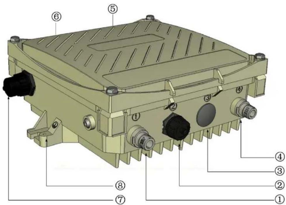
| 1 | Antenna interface (Radio 1) | 5 | Antenna interface (Radio 0) |
| 2 | USB console interface | 6 | Antenna interface (Radio 1) |
| 3 | Reserved or Power interface | 7 | Ethernet interface (POE) |
| 4 | Antenna interface (Radio 0) | 8 | Grounding hole |
1.2 LED Status Indicators
The MSR2000 include visual indicators for power, link and radio status.
Figure 1-2 LED layout
| R0 (Row of five) | ||||
| R1 (Row of five) | ||||
| P/S | POE | ETH | ||
The table below lists the meanings of the LEDs on the MSR2000.
Table 1-1 MSR2000 LED status indicators
| LED | Color | QTY | Definition |
| R0 | Blue | 5 | Displays the Radio 0 RF Strength status:All dark: Radio 0 is not providing either access (SSID) or backhaul (mesh) serviceSingle LED blue: Radio 0 is providing access (SSID) service or providing very weak backhaul (mesh) linkMultiple LED blue: Radio 0 is providing backhaul (mesh) link to another node; the more LEDs are blue, the stronger the link signal |
| R1 | Blue | 5 | Displays the Radio 1 RF Strength status:All dark: Radio 1 is not providing either access (SSID) or backhaul (mesh) serviceSingle LED blue: Radio 1 is providing access (SSID) service or providing very weak backhaul (mesh) linkMultiple LED blue: Radio 1 is providing backhaul (mesh) link to another node; the more LEDs are blue, the stronger the link signal |
| P/S | Orange/Green | 1 | Displays the power or connection status:Dark: No power to the unitOrange: Unit has power but does not yet have a mesh network routing path to a gateway (portal) nodeGreen: Unit has power and has found a mesh network routing path to a gateway (portal) node |
| POE | 1 | Not currently used | |
| ETH | Yellow/Green | 1 | Display the Gigabit-Ethernet 0 link status:Dark: No uplink on the Ethernet portGreen: The link speed is 1000MYellow: The link speed is 10M or 100MFlashing: Data is being transmitted or received |
2 Installation Preparations
This chapter describes the preparations for MSR2000 installation, including preparation of installation tools, selection of installation sites and etc.
2.1 Preparing Installation Tools
When installing MSR2000, you may need the following tools. You shall select the tools according to the actual situation.
Table 2-1 Installation tools list
| Type | Tools |
| General tools | Screwdriver, adjustable spanner, vice, safety belt, hard hat, power board (220 VAC or as required by local regulation), POE power injector, crimping pliers, electric soldering iron, welding wire, PVC insulation tape, adhesive insulation tape, strap, insulation tools |
2.2 Examining the Installation Site
-
The site should be located within at least a 60% range of the 1st fresnel zone without obstacles to provide LOS transmission, increase coverage capacity, and minimize the number of necessary sites.
-
If no LOS secured, area in NLOS area could be covered as well, but the distance of coverage and area of coverage are decreased; more sites are needed to provide coverage for same area than in the LOS scenario.
-
Interference must be considered in site selection. New site should avoid known interference, unless the interference is controllable.
-
Keep the MSR2000 away from places that are susceptible to high temperature, dust, harmful gas, inflammable, explosive, electromagnetic interference (high power radar, radio station and transformer), unstable voltage, heavy vibration, or loud noise. In engineering design, the site should be selected according to the network planning and technical requirements of communications equipment, as well as the considerations such as climate, hydrology, geology, earthquake, electric power, and transportation.
3 MSR2000 Installation
The installation flowchart of MSR2K23N0:
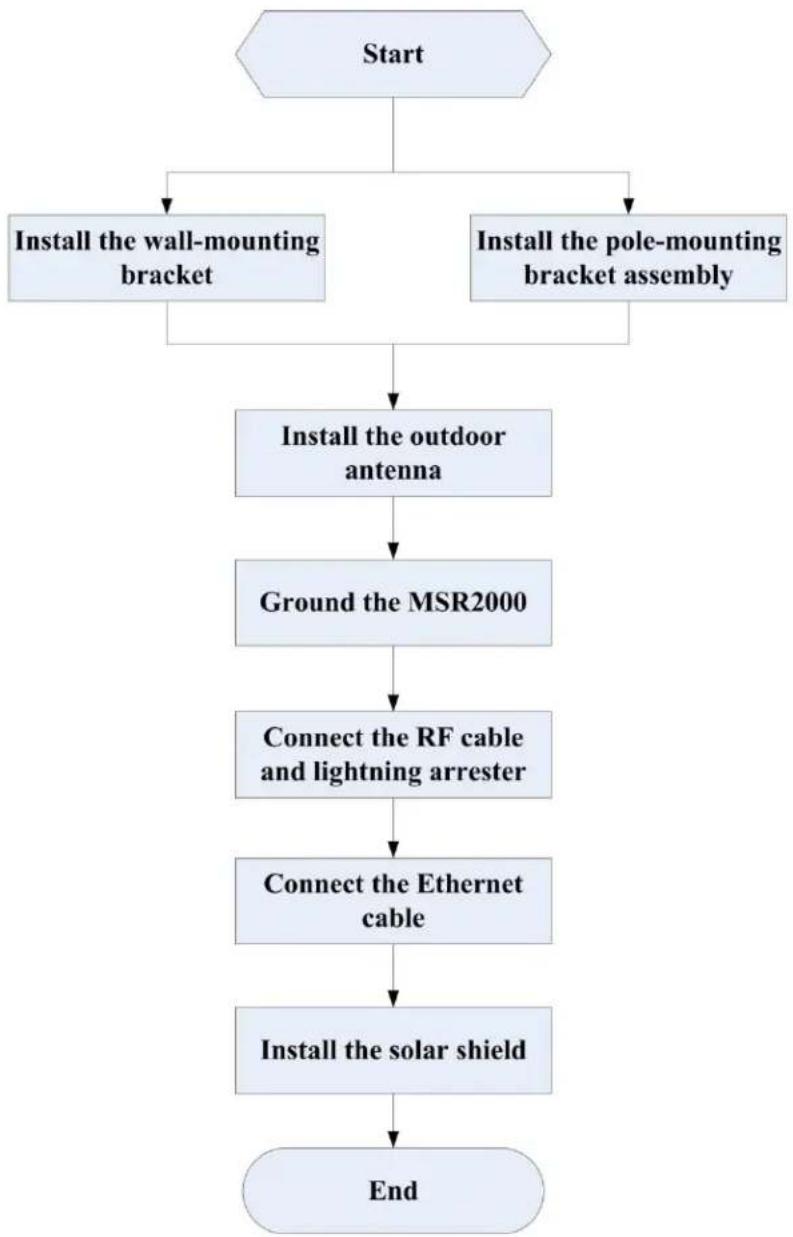
flowchart
graph TD
    A["Start"] --> B["Install the wall-mounting bracket"]
    A --> C["Install the pole-mounting bracket assembly"]
    B --> D["Install the outdoor antenna"]
    C --> D
    D --> E["Ground the MSR2000"]
    E --> F["Connect the RF cable and lightning arrester"]
    F --> G["Connect the Ethernet cable"]
    G --> H["Install the solar shield"]
    H --> I["End"]
3.1 Installing MSR2000 on a pole
The mounting bracket assembly for installing MSR2000 concludes: a solar shield, a pair of pole anchors, a mounting bracket and bolts. MSR2000 can be mounted on a pole or wall. (Pole diameter must be 40 to 60 mm at the position where the MSR2000 will be mounted.)

Note
- If using M8 x150 long bolts (not provided in the box shipped with MSR2000), the MSR2000 can be mounted on a pole with 96mm diameter.
Figure 3-1 the pole anchors and mounting bracket
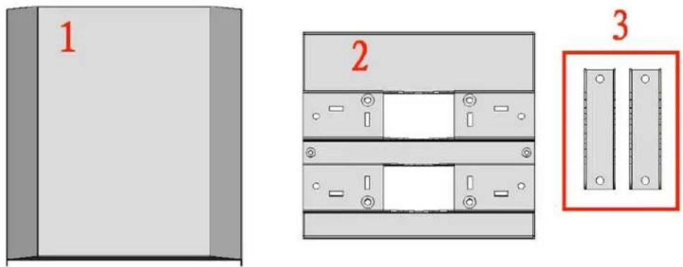
| 1 | A solar shield | 2 | A mounting bracket |
| 3 | A pair of pole anchors |
Figure 3-2 Bolts
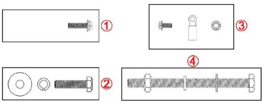
| 1 | {M4 x16 bolt (flat washer, spring washer)}x4 | 3 | {M4 x12 bolt, external-tooth washer, OT copper lug}x1 |
| 2 | {M6 x30 bolt, flat washer, spring washer}x2 | 4 | {M8 x110 bolt, flat washer, spring washer, nut}x4 |
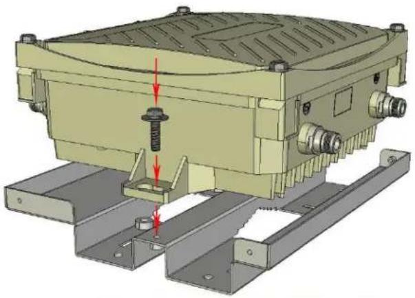
Step 1 Fix the MSR2000 on the mounting bracket using the two M6 x30 bolts (with flat and spring washers) on each side of the mounting bracket. (There is screw thread in the screw hole of the mounting bracket)
Figure 3-3 Fix MSR2000 on the mounting bracket
natural_image
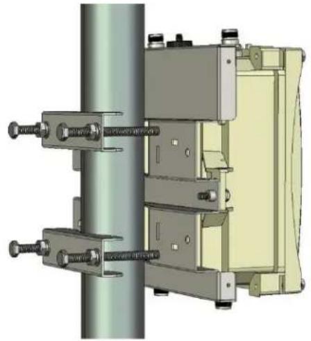
3D mechanical assembly diagram showing a housing with mounting flanges and a red arrow indicating force or movement (no text or symbols present)Step 2 Fix the mounting bracket (with MSR2000) on the pole using four M8 x110 bolts (with flat washers, spring washers and nuts) and the pair of pole anchors.
Figure 3-4 Fix the mounting bracket (with MSR2000) on the pole
natural_image
3D mechanical assembly diagram showing two vertical components connected to a cylindrical shaft (no visible text or symbols)3.2 Installing MSR2000 on a wall
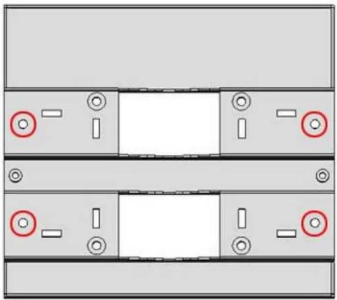
Step 1 Mark
1) Put the mounting bracket on the installation position against the wall.
2) Mark four expansion screw holes on the wall.
Figure 3-5 Positions of screw holes
natural_image
Top-down view of a server rack with multiple slots and indicator lights (no text or symbols)Step 2 Drill holes
1) Use a percussion drill to drill four holes on the four markings. (Expansion screw size: M6 x 60mm)
Step 3 Install masonry anchors
1) Insert a masonry anchor into each drilled hole vertically.
2) Tap the flat end of the anchor with a rubber hammer until the anchor is flush with the wall surface.
Step 4 Fix the wall-mounting bracket
1) Align the four holes in the wall-mounting bracket with the anchors and insert four expansion screws through the installation holes into the anchors.
2) Adjust the position of the wall-mounting bracket and tighten the expansion screws.
Step 5 Fix MSR2000 on the wall-mounting bracket
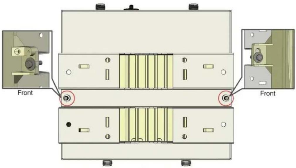
1) Fix the MSR2000 on the wall-mounting bracket by inserting the two M6 x30 bolts (with flat and spring washers) through the installation holes, and tighten the bolts. (There is screw thread in the screw hole of the mounting bracket)
Figure 3-6 Positions of installation holes on MSR2000
3.3 Grounding the MSR2000
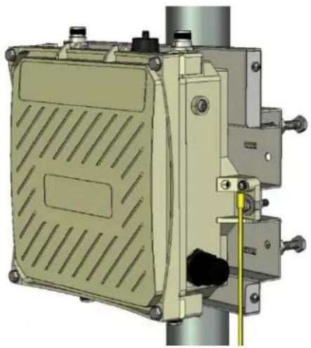
The grounding must be completed before powering up the MSR2000. The residence of grounding wire should be less than 5 ohm and the grounding cable's cross-section area should be no less than 6mm^2 . The grounding hole is at the left side of the MSR2000.
Figure 3-7 Grounding the MSR2000
natural_image
3D technical illustration of a mechanical device with mounting bracket and vertical guide (no text or symbols)ARUBA®
networks
Step 1 Peel the cover of one end of the grounding cable (green or yellow and green grounding cable with 6 mm ^2 cross-section area) and place the bare grounding cable into the copper lug, and press firmly with the crimping pliers.
Step 2 Fasten the copper lug to the grounding hole on the MSR2000 with the M4 x12 bolt and external-tooth washer.
3.4 Connecting the RF cable
The RF cable is used to connect antenna and the MSR2000. (Note: you should install lightning arrester between antenna and the MSR2000.)
Figure 3-8 Connecting the RF cable
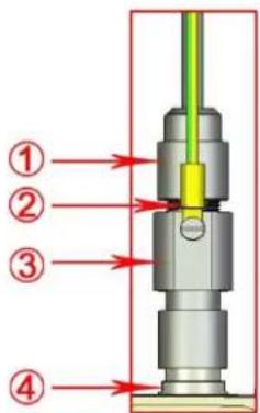
| 1 | RF cable with N type connector | 3 | lightning arrester |
| 2 | Grounding cable for lightning arrester | 4 | Antenna interface |
Step 1 Screw one end of the lightning arrester onto the antenna interface.
Step 2 Connect the RF cable to the other end of the lightning arrester.
Step 3 Water-proof the antenna connection with PVC insulation tape, adhesive insulation tape and strap.
3.5 Connecting the Ethernet cable
To ensure that your MSR2K23N0 maintains Ethernet connectivity and Power over Ethernet (PoE), you must use the included weatherproof connector kit and install it using the steps below.

Note
- Failure to use the included weatherproof connector kit can lead to connectivity and PoE issues.
Figure 3-9 Weatherproof Connector Kit
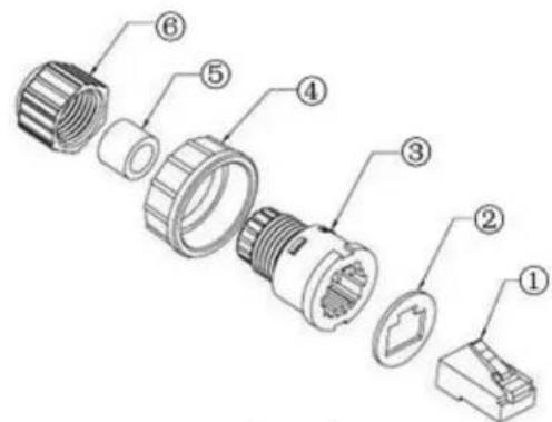
| 1 | Shielded RJ45 connector | 4 | Locknut |
| 2 | Gasket mat | 5 | Seal ring |
| 3 | Waterproof connector socket | 6 | Sealing nut |
- Remove the cover from the adhesive side of the gasket mat and place it over the weatherproof connector socket.
- Place the locknut over the weatherproof connector socket.
- Place the sealing nut over an Ethernet cable (without a connector attached to the end).
- Place the seal ring over the Ethernet cable.
- Insert the Ethernet cable into the narrow end of the weatherproof connector socket and pass it through the opening on the wide end.
- Using a crimping tool, attach the included shielded RJ45 connector.
- Slide the seal ring up the Ethernet cable and insert it into the narrow end of the weatherproof connector socket.
- Pull the Ethernet cable so the shielded RJ45 connector fits into the RJ45 shaped opening in the wide end of the weatherproof connector socket.
- Slide the sealing nut over the narrow end of the weatherproof connector socket and hand tighten it.
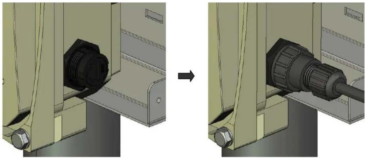
- Insert the Ethernet cable connector into the Ethernet interface and hand-tighten the locknut.
- Water-proof the Ethernet cable connection with PVC insulation tape and adhesive tape.
Figure 3-10 Connecting Ethernet cable
natural_image
Mechanical assembly diagram showing a bolted connector being inserted into a housing, before and after modification (no text or symbols present)3.6 Fixing the solar shield on MSR2000
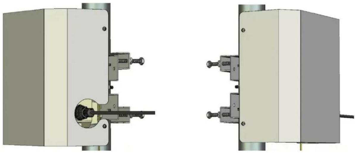
Step 1 Fix the solar shield on MSR2000 by using the four M4 x16 bolts (with flat and spring washers).
Figure 3-11 Fixing the solar shield on MSR2000
natural_image
Technical diagram showing two mechanical assembly views (left and right) with no visible text, numbers, or symbols.4 Installing an Outdoor Antenna
There are two two types of outdoor antennas: directional antenna and omni antenna. The following will introduce the installation of directional antenna and omni antenna.
4.1 Installing a directional outdoor antennal
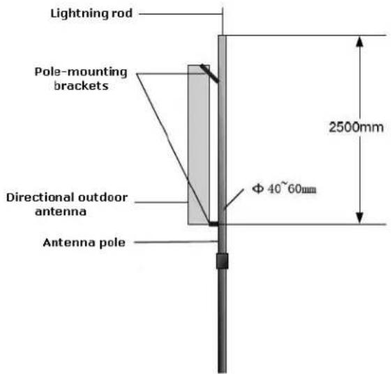
◆ Install the lightning rod
Figure 4-1 Weld the lightning rod onto the top of the pole
◆ Install the directional antenna
Step 1 Fix the directional antenna on the pole. (Pole diameter: 40-60mm)
Step 2 Adjust the direction of the antenna and tighten the screws.
4.2 Installing an omni outdoor antenna
◆ Install the lightning rod
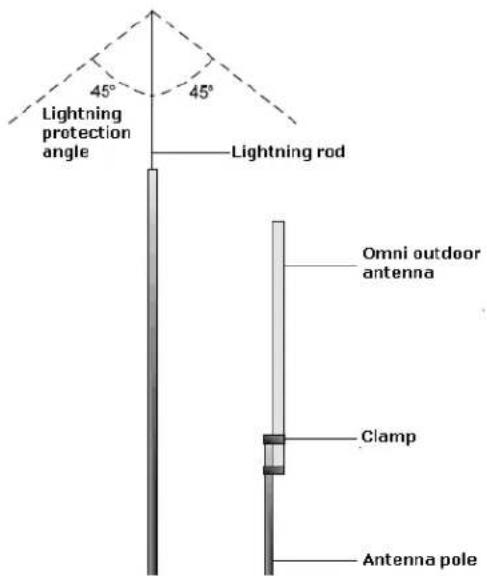
When installing an omni outdoor antenna on a pole, the top of the pole should be flush with the upper clamp, as shown in figure below. The antenna height should meet the signal coverage requirement and the top of the antenna should be within the 45^ protection angle.
Figure 4-2Weld the lightning rod onto the top of the pole
◆ Install the omni antenna
Step 1 Fix the antenna on the pole (Pole diameter: 40-60mm).
Step 2 Adjust the omni antenna to ensure the antenna is vertical and tighten the screws.

Note
- Safety protection must be guaranteed when working aloft
- The installation should be done by an experienced antenna installer. Power lines and high electric fields must be avoided.
- Don't stand on side of antenna when MSR2000 is operating as there are strong electromagnetic fields surrounding the antenna.
- Do not install or remove cables or antennas in the rain.
- Be sure to use DC grounding antenna with lightning protection to prevent dangers of surges and static electricity.
5 Note
• To log onto the MSR2000 via Console port, use the setting as shown in table below:
| Baud Rate | 115200 |
| Data Bits | 8 |
| Parity | None |
| Stop Bits | 1 |
| Flow Control | None |
| Default Username and Password | root : public |
- Aruba Networks MSR2000 Installation Guide
- Statement of Conditions
- DISCLAIMER: LIMITATION OF LIABILITY
- ARUBA®
- Safety and Regulatory Compliance
- Safety Warnings
- General Safety Warnings
- Working Aloft Warning
- Lightning Activity Warning
- Explosive Device Proximity Warning
- Antenna Placement Warning
- Antenna Selection Warning
- Grounding Warning
- Power Installation Warning
- Solar Irradiation and High Temperature Protection
- RF Device Protection
- FCC Certificate
- REMINDER
- NOTICE
- RF Radiation Exposure Statement
- IC notice
- RoHS for MSR2K23N0
- European Union RoHS
- RoHS
- China RoHS
- Table of Contents
- PRODUCT OVERVIEW 9
- INSTALLATION PREPARATIONS ....11
- MSR2000 INSTALLATION 12
- INSTALLING AN OUTDOOR ANTENNA....21
- NOTE....23
- Product Overview
- Note
- Interfaces
- LED Status Indicators
- Installation Preparations
- Preparing Installation Tools
- Examining the Installation Site
- MSR2000 Installation
- Installing MSR2000 on a pole
- Installing MSR2000 on a wall
- Step 1 Mark
- Step 2 Drill holes
- Step 3 Install masonry anchors
- Step 4 Fix the wall-mounting bracket
- Step 5 Fix MSR2000 on the wall-mounting bracket
- Grounding the MSR2000
- networks
- Connecting the RF cable
- Connecting the Ethernet cable
- Fixing the solar shield on MSR2000
- Installing an Outdoor Antenna
- Installing a directional outdoor antennal
- Installing an omni outdoor antenna
- ◆ Install the omni antenna
- Note
Brand : Aruba
Model : AirMesh MSR2000
Category : Router