
IS760D - Scanner RICOH - Free user manual and instructions
Find the device manual for free IS760D RICOH in PDF.


| Product Type | Flatbed color scanner with Automatic Document Feeder (ADF) |
| Model | Ricoh IS760D |
| Scanning Method | Fixed document (exposure glass) and moving document (ADF); duplex model supports simultaneous two-sided scanning |
| Optical Resolution | 400 dpi (main and sub scanning) |
| Scanning Grade | Input: 10 bits per pixel per color; Output: 1 bit (binary) or 8 bits per pixel per color |
| ADF Scanning Speed | Simplex binary: 75 ppm (8.5" x 11", 200 dpi); Duplex binary: 122 ipm; Simplex color: 40 ppm; Duplex color: 62 ipm |
| Maximum Scan Area (ADF) | One side color: 12" x 24.8" (297 x 630 mm); One side monochrome: 12" x 78.7" (297 x 2000 mm); Both side: 12" x 17" (297 x 432 mm) |
| Maximum Scan Area (Exposure Glass) | 12" x 17" (297 x 432 mm) |
| Original Sizes (Auto Detect) | Standard sizes: A3, A4, A5, B4, B5, B6, Legal, Letter, 11" x 17", etc.; requires black background panel for mixed-size detection |
| Paper Weight (ADF) | 40–157 g/m² (77–298 lbs) |
| ADF Capacity | 200 sheets (8.5" x 11", 64 g/m²) |
| Interfaces | Standard: SCSI-3, USB 2.0; Optional: IEEE1394 (2 ports, alternative with USB) |
| Power Source | 120 V, 60 Hz, 10 A or more |
| Power Consumption | Operation: 180 W; Standby: 50 W; Low-Power mode: 8 W |
| Warm-up Time | Max. 20 seconds |
| Low-Power Mode Transition/Recovery | Transition: approx. 15 minutes; Recovery: 3 seconds or less |
| Dimensions (W x D x H) | 19.3" x 27.4" x 13" (490 x 695 x 332 mm) |
| Weight | Simplex: approx. 68.3 lbs (31 kg); Duplex: approx. 72.8 lbs (33 kg) |
| Operating Environment | Temperature: 50–90°F (10–32°C); Humidity: 15–80% |
| Duty Cycle (Life) | ADF: 3,000,000 scans; Flatbed: 600,000 scans or 5 years |
| Software Included | TWAIN driver, ISIS driver, DeskTopBinder Lite, QuickScan |
| Cleaning | Clean rollers every 3 months, ventilation filter every 6 months; use dry cloth or damp cloth with water/mild detergent; avoid benzene/thinner |
| Safety Features | Automatic power-off, lock screws for transport, hard reset switch, error indicators |
| Energy Star Compliant | Yes, meets ENERGY STAR guidelines |
Frequently Asked Questions - IS760D RICOH
User questions about IS760D RICOH
0 question about this device. Answer the ones you know or ask your own.
Ask a new question about this device
Download the instructions for your Scanner in PDF format for free! Find your manual IS760D - RICOH and take your electronic device back in hand. On this page are published all the documents necessary for the use of your device. IS760D by RICOH.
USER MANUAL IS760D RICOH
Operating Instructions
Guide to Components
Setting up the Scanner
Installing Software
Setting Originals
Using the TWAIN Driver
Appendix
Introduction
This manual contains detailed instructions and notes on the operation and use of this machine. For your safety and benefit, read this manual carefully before using the machine. Keep this manual in a handy place for quick reference.
Two kinds of size notation are employed in this manual. With this machine refer to the inch version.
Important
Contents of this manual are subject to change without prior notice. In no event will the company be liable for direct, indirect, special, incidental, or consequential damages as a result of handling or operating the machine.
Caution
Certain options might not be available in some countries. For details, please contact your local dealer.
Some illustrations in this manual might be slightly different from the machine.
The supplier shall not be responsible for any damage or expense that might result from the use of parts other than genuine parts from the supplier with your office products.
Do not copy or print any item for which reproduction is prohibited by law.
Copying or printing the following items is generally prohibited by local law:
bank notes, revenue stamps, bonds, stock certificates, bank drafts, checks, passports, driver's licenses.
The preceding list is meant as a guide only and is not inclusive. We assume no responsibility for its completeness or accuracy. If you have any questions concerning the legality of copying or printing certain items, consult with your legal advisor.
Power Source
Color Scanner: 120V, 60Hz, 10A or more
Please be sure to connect the power cord to a power source as above.
Trademarks
Adobe, PostScript, and Acrobat are trademarks of Adobe Systems Incorporated.
QuickScan ^™ is a trademark of Pixel Translations and Captiva Software Corporation.
PixTools® and ISIS® are registered trademarks of Pixel Translations and Captiva Software Corporation.
Pentium is a registered trademark of Intel Corporation.
MS, Microsoft, and Windows are registered trademarks of Microsoft Corporation.
Other product names used herein are for identification purposes only and might be trademarks of their respective companies. We disclaim any and all rights to those marks.
The proper names of the Windows operating systems are as follows:
- The product name of Windows ^ 95 is Microsoft ^ Windows ^ 95
- The product name of Windows ^ 98 is Microsoft ^ Windows ^ 98
- The product name of Windows ^ Me is Microsoft ^ Windows ^ Millennium Edition (Windows Me)
- The product names of Windows ^ 2000 are as follows: Microsoft ^ Windows ^ 2000 Professional Microsoft ^ Windows ^ 2000 Server Microsoft ^ Windows ^ 2000 Advanced Server
- The product names of Windows ^ XP are as follows: Microsoft ^ Windows ^ XP Home Edition Microsoft ^ Windows ^ XP Professional
- The product names of Windows Server™ 2003 are as follows: Microsoft® Windows Server™ 2003 Standard Edition Microsoft® Windows Server™ 2003 Enterprise Edition Microsoft® Windows Server™ 2003 Web Edition
- The product names of Windows ^ NT 4.0 are as follows: Microsoft ^ Windows NT ^ Workstation 4.0 Microsoft ^ Windows NT ^ Server 4.0
TABLE OF CONTENTS
Safety Information .... 1
Safety During Operation.... 1
Energy Star Program 4
Manuals for This Scanner ....5
How to Read This Manual ....6
1. Guide to Components
Guide to This Scanner....7
Understanding Indicators 9
DIP Switches....10
2. Setting up the Scanner
Confirmations Before the Setup....11
Location, Space and Environment ....11
Disengaging the lock for transportation....13
Installing Options....16
Installing the Image-Processing Unit....16
Installing the IEEE1394 Interface Board 18
Connecting to the Computer ....21
Connecting with SCSI Interface 21
About the SCSI Interface....21
Setting the SCSI ID 22
Setting the SCSI ID Automatically 23
Connecting the SCSI Cable (When the Scanner is at the End of the Daisy Chain)...24
Connecting the SCSI Cable (When the Scanner is not at the End of the Daisy Chain)...26
Using the Scanner only with the SCSI Connection ....27
Connecting with USB Interface 28
Connecting with IEEE1394 Interface 29
Connecting to a Power Source....31
Turning the Power On/Off 33
Turning the Power On when Connected with SCSI Interface 33
Turning the Power On when Connected with USB/IEEE1394 Interface ....33
Turning the Power Off 33
Using the Hard Reset Switch....34
3. Installing Software
Installing TWAIN Driver 35
System Requirements....35
Installing TWAIN Driver....36
Installing DeskTopBinder Lite ....38
System Requirements....38
Installing DeskTopBinder Lite 39
Installing ISIS Driver ....40
System Requirements....40
Installing ISIS Driver....41
Installing QuickScan....43
System Requirements....43
Installing QuickScan.... 43
4. Setting Originals
Sizes and Weights of Recommended Originals....45
Original Sizes Available for Auto Detection 46
Originals that Require Special Care....47
Placing Originals....48
Placing the Original on the Exposure Glass....48
Placing the Originals in the ADF 49
Changing the Color of the Background Panel 52
Changing the Color of the Background Panel for the ADF 52
Changing the Color of the Background Panel for the Exposure Glass ....54
5. Using the TWAIN Driver
Procedure Breakdown....57
Scanning Originals ....58
What You Can Do with the TWAIN Driver 60
Functions of the TWAIN Driver 60
6. Appendix
Troubleshooting....63
Error Indicators....63
When the Original is Jammed or Double Fed in the ADF 64
When the Originals are Not Fed Correctly 66
When Scanning is Not Performed as Expected 66
When an Error Message Appears 67
When in Installation and Other Problems....70
Cleaning....71
Cleaning the Original Table Cove 72
Cleaning Under the Pressure Panel....73
Cleaning Under the Background Panel....74
Cleaning Inside the ADF Cover....76
Cleaning the Ventilation Panel 77
Moving and Transporting the Scanner 78
Moving Over Short Distances 78
Transporting the Scanner....79
Disposing of the Scanner....81
How Data Size Changes Depending on Scan Area and Resolution......82
When [Binary(Text)], [Binary(Photo)], [Binary(Auto Image)], or [Binary(Text/Photo)] is Selected...82
When [Gray Scale] or [256 Colors] is Selected 83
When [8 Colors] or [8 Colors(Photo)] is Selected 83
When [16770K colors] is Selected....84
Options 85
Image Processing Unit Type B....85
IEEE1394 Interface Unit Type IS760 85
Specifications....86
INDEX....88
Safety Information
When using this machine, the following safety precautions should always be followed.
Safety During Operation
In this manual, the following important symbols are used:

WARNING:
Indicates a potentially hazardous situation which, if instructions are not followed, could result in death or serious injury.

CAUTION:
Indicates a potentially hazardous situation which, if instructions are not followed, may result in minor or moderate injury or damage to property.
WARNING:
- Connect the Power Cord directly into a wall outlet and never use an extension cord.
- Disconnect the power plug (by pulling the plug, not the cable) if the power cable or plug becomes frayed or otherwise damaged.
- To avoid hazardous electric shock or laser radiation exposure, do not remove any covers or screws other than those specified in this manual.
-
Turn off the power and disconnect the power plug (by pulling the plug, not the cable) if any of the following conditions exists:
-
You spill something into the equipment.
- You suspect that your equipment needs service or repair.
-
Your equipment's cover has been damaged.
-
Disposal can take place at our authorized dealer or at appropriate collection sites.
- Keep the machine away from flammable liquids, gases, and aerosols. A fire or an electric shock might occur.
- Make sure the wall outlet is near the machine and easily accessible so that in event of an emergency it can be unplugged easily.
- Do not use with a power source with a voltage different from the specified voltage. Do not use a power outlet with multiple devices plugged in. These could create the risk of fire or electric shock.
- Avoid the use of an extension cord.
- Do not damage, break, twist or modify the Power Cord. Placing heavy objects on the cord, pulling on or bending it excessively can damage the Power Cord, creating the risk of fire or electric shock.
- Never touch or unplug the power plug with wet hands. This can create the risk of electric shock.
- Never remove any covers or screws other than those specified in this manual. The inside of the scanner contains high-voltage components that can cause electrical shock. Have all inspections, adjustments, and repairs inside the scanner performed by an authorized dealer only.
- Do not attempt to modify this scanner in any way. Modification can cause fire or electrical shock.

CAUTION:
- Protect the equipment from dampness or wet weather, such as rain, snow, and so on.
- Unplug the Power Cord from the wall outlet before you move the equipment.
While moving the equipment, you should take care that the Power Cord will not be damaged under the equipment. - When you disconnect the power plug from the wall outlet, always pull the plug (not the cable).
- Do not allow paper clips, staples, or other small metallic objects to fall inside the equipment.
- For environmental reasons, do not dispose of the equipment or expended supply waste at household waste collection points. Disposal can take place at an authorized dealer or at appropriate collection sites.
- The inside of the machine could be very hot. Do not touch the parts with a label indicating the "hot surface". Otherwise it could cause a personal burn.
- Our products are engineered to meet high standards of quality and functionality, and we recommend that you only use the expendable supplies available at an authorized dealer.
- Keep the machine away from humidity and dust. A fire or an electric shock might occur.
- Do not place the machine on an unstable or tilted surface. If it topples over, it could cause injury.
- When unplugging from an outlet, be sure to grasp the plug when pulling. Never pull on the cord. This could damage the cord creating the risk of fire or electrical shock.
- When disconnecting the power cord, always make sure to hold onto the plug. Do not pull on the power cord itself. This can cause damage to the cord, fire or electrical shock.
- Be careful not to pinch your fingers when closing the Automatic Document Feeder (ADF).
• This scanner weighs approximately 72.8 lbs. - Make sure to lift it carefully with two persons or more so as to minimize physical strain. Careless lifting, reckless handling or allowing it to drop down can cause injury.
- When transporting over long distances, please consult an authorized dealer.
Energy Star Program
ENERGY STAR®

As an ENERGY STAR Partner, we have determined that this machine model meets the ENERGY STAR Guidelines for energy efficiency.
The ENERGY STAR Guidelines intend to establish an international energy-saving system for developing and introducing energy-efficient office equipment to deal with environmental issues, such as global warming.
When a product meets the ENERGY STAR Guidelines for energy efficiency, the Partner shall place the ENERGY STAR logo onto the machine model.
This product was designed to reduce the environmental impact associated with office equipment by means of energy-saving features, such as Low-power mode.
◆Low-Power mode
This unit automatically lowers its power consumption at a predetermined time (approximately 15 minutes) after the last operation was performed. To operate the unit from this mode, see the instructions below.
• Method for clearing
- Put a document on the Original Table.
- Open the cover of the Automatic Document Feeder (ADF).
- Lift the Pressure Panel.
- Follow the instructions from the PC.
Note
☐The Low-Power mode does not work in the following conditions.
- When an error occurs.
- When a document is placed on the Original Table.
Specifications
| Low-Power mode Power consumption Approx. 8W | |
| Transitional interval 15 minutes |
Manuals for This Scanner
The following manuals describe the operational and maintenance procedures of this machine.
To enhance safe and efficient operation of this scanner, all users should read and follow the instructions carefully.
◆ Quick Installation Guide
Describes how to install the scanner.
◆ Operating Instructions (this manual)
Provides all of the information how to install, set up, and use the scanner. This manual is provided as a PDF file.
Note
☐ There is a CD-ROM that comes with this scanner.
How to Read This Manual
Symbols
The following set of symbols is used in this manual.
⚠ WARNING:
This symbol indicates a potentially hazardous situation that might result in death or serious injury when you misuse the machine without following the instructions under this symbol. Be sure to read the instructions, all of which are described in the Safety Information section.
CAUTION:
This symbol indicates a potentially hazardous situation that might result in minor or moderate injury or property damage that does not involve personal injury when you misuse the machine without following the instructions under this symbol. Be sure to read the instructions, all of which are described in the Safety Information section.
* The statements above are notes for your safety.
Important
If this instruction is not followed, paper might be misfed, originals might be damaged, or data might be lost. Be sure to read this.
Preparation
This symbol indicates information or preparations required prior to operating.
Note
This symbol indicates precautions for operation, or actions to take after abnormal operation.
Limitation
This symbol indicates numerical limits, functions that cannot be used together, or conditions in which a particular function cannot be used.
Reference
This symbol indicates a reference.
[ ]
Keys that appear on the machine's display panel.
[ ]
Keys and buttons that appear on the computer's display.
【 】
Keys built into the machine's control panel.
【 】
Keys on the computer's keyboard.
1. Guide to Components
Guide to This Scanner
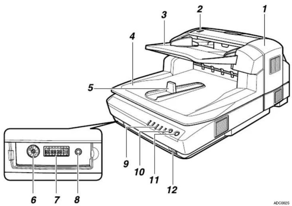
1. ADF (Automatic Document Feeder)
Allows you to automatically load multiple originals into this machine.
2. Paper Thickness Changeover Lever
When you scan the thick originals — originals thicker than 128g/m^2 (242.5bls) — with the ADF, set the paper thickness changeover lever to your side. After scanning, return the switch to the back side.
3. Original Table
Set originals here to be loaded into this machine using ADF.
4. Output Table
The originals that have been loaded by the ADF are output here after scanning.
5. Original Stopper
Stops the originals scanned by the ADF.
6.Rotary Switch
Use to set SCSI ID.
7.DIP Switches
Use to set the operation mode of this scanner. p.10 "DIP Switches"
8.Hard Reset Switch
This switch resets the power to the scanner. Use this switch when validate the settings of the DIP Switches or the Rotary Switch.
9.Indicators
Indicates the status of this machine. p.9 "Understanding Indicators"
10.【Clear Modes】key
Press this key to stop the manual scanning.
11.【[Start] key
Press this key to start the manual scanning
12.Power Switch
Turns this machine's power on and off.

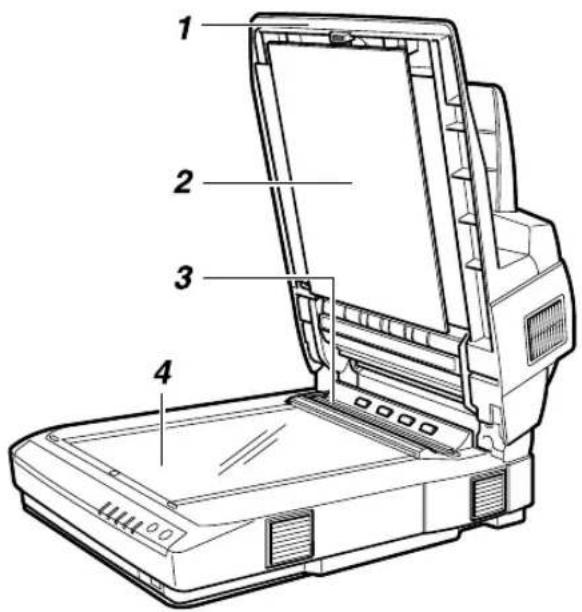
1. Pressure Panel
Holds the originals down on the Exposure Glass.
2. Background Panel for Exposure Glass
Panel to set the background color for the original in black or white when you place the original on the exposure glass. p.54 "Changing the Color of the Background Panel for the Exposure Glass"
3.ADF Exposure Glass
Scans the originals when they are loaded by the ADF.
4.Exposure Glass
Set the original here when you do not use the ADF scanning.
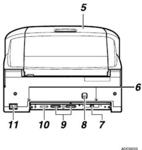
5.ADF Cover
Open when clearing the misfed originals or cleaning the rollers.
6.Lock Screw
This is to lock the scanning parts inside when you transport this machine. Remove this screw when you set up this machine.
7.USB 2.0 Interface Connector
Used for connection of an USB cable. The USB interface board is alternatively used with the optional IEEE1394 interface board.
8.Lock Lever
Set this lever to the "Lock" position when you transport this machine.
9.SCSI Interface Connector
Used for connection of a SCSI Cable.
10.SD Card Slot
Used for an authorized customer engineer's maintenance only.
11.Power Connector
For connection of the bundled AC power code.
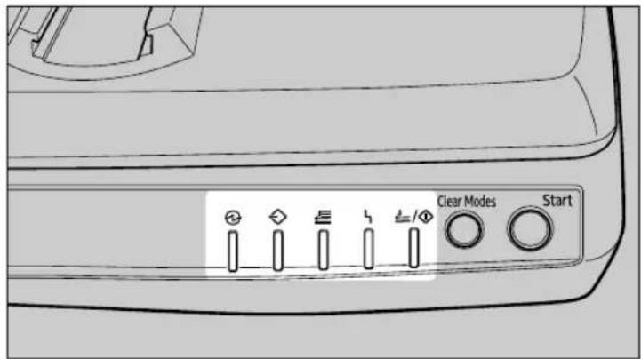
Understanding Indicators
This section explains how to interpret the indicators in front of this machine.
ADC1265
| Indicators On Blink Off | |||
 | Status of Power Power On Low-Power mode Power Off | ||
 | Machine Busy Scanning operation in progress *1 | ||
| [WASW] | Documents in place | Originals are set to the ADF | |
| ### | Error detection Error No error or the | current status | |
| ### | Scan Wait SADF When SADF mode or during standby for the manual scan | ||
*1 Sometimes it looks like blinking.
All indicators on: For a short while after you turned on the power, or pressed the Hard Reset key.
All indicators blinking: System error. Contact your service representative.
Description of the Error indicator on: See p.63 "Error Indicators"
DIP Switches
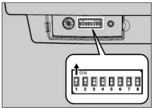
Change only the switches No. 1 to 3. Do not change the other switches.
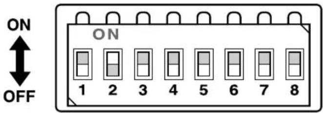
ADCDD5S
| SW No. | Function OFF ON | ||
| 1 | SCAM^*1 | disable enable | |
| 2 SCSI | synchronous transmission enable | disable | |
| 3 SCSI | termination enable disable | ||
| 4 | (system usage) | always OFFDo not make changes. | |
| 5 | |||
| 6 | |||
| 7 | |||
| 8 | |||
*1 SCAM: SCSI Configured Automatically. Protocol to set SCSI ID automatically.
Important
☐SCSI ID will not be configured even if you set SCAM to enable, when more than one of this scanner with the SCAM function enabled are connected to the daisy chain. In this case, disable the SCAM by setting the DIP Switch No.1 ON, and set the SCSI ID with the Rotary Switch.
☐The USB and the optional IEEE1394 connection cannot be used when the SCSI synchronous transmission is set. You can turn the DIP Switch No.2 OFF (SCSI synchronous transmission enabled) when using the scanner only with the SCSI connection.
☐A malfunction with SCSI synchronous transmission may occur if you use a SCSI cable longer than recommended, or a cable out of the standard. In that case, turn the DIP Switch No.2 ON (SCSI synchronous transmission disabled).
☐When the scanner is connected to the middle of the daisy chain, set the DIP Switch No.3 ON.
2. Setting up the Scanner
This section explains how to setup the scanner to get it ready for use, and how to make necessary connections.
Confirmations Before the Setup
Location, Space and Environment
Location
WARNING:
- Make sure the wall outlet is near the machine and easily accessible so that in event of an emergency it can be unplugged easily.
CAUTION:
- Keep the machine away from humidity and dust. A fire or an electric shock might occur.
- Do not place the machine on an unstable or tilted surface. If it topples over, it could cause injury.
Place the scanner on a level, stable, vibrating-free surface.
- Allowable inclination of the surface for installation is within 0.2inch (when measuring difference of heights between one end and the other of this machine, compared to a level surface).
Space
Make sure that the scanner is in a location where there is enough space to provide the clearance as illustrated below, and also provide a comfortable working area in the front.
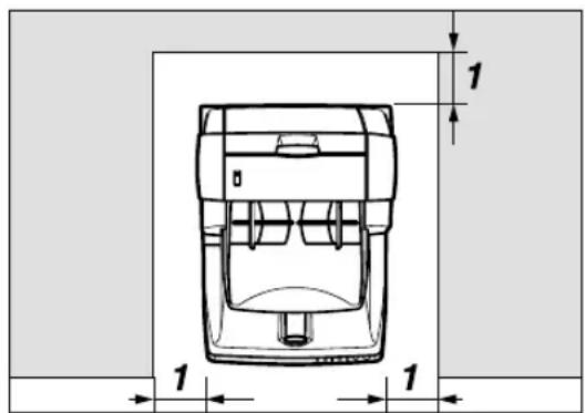
- 4 inch (100 mm) or more
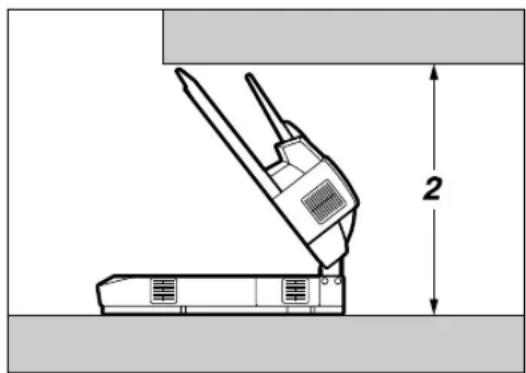
ADC120S
2. 31.5 inch (800 mm) or more
Environment
Important
☐Do not set up the scanner in any of the following types of locations. It may be the cause of the malfunction.
• In a location exposed to direct sunlight
- In a location where the scanner will be subjected to blowing air or radiant heat, such as near an air conditioner or heater
- In a location near other electronic devices, such as a radio or television set
- In a location subject to extreme temperatures or humidity
- Near a humidifier
Set up the scanner in a location where the temperature and humidity will fall within the ranges shown below.
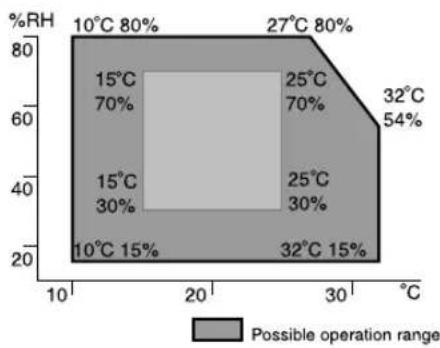
heatmap
| Temperature Range | Percentage (%) | | :--- | :--- | | 10°C - 80% | 80 | | 15°C - 70% | 70 | | 15°C - 30% | 30 | | 27°C - 80% | 80 | | 25°C - 70% | 70 | | 25°C - 30% | 30 | | 32°C - 54% | 54 | | 32°C - 15% | 15 | The chart displays a shaded region representing the possible operation range for each zone. The x-axis is labeled in degrees Celsius (°C), and the y-axis is labeled as %RH. The legend indicates that gray shading corresponds to the possible operation range.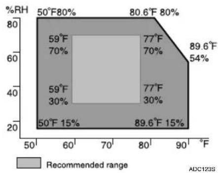
heatmap
| Temperature Range (°F) | %RH (%) | | :--- | :--- | | 50-60 | 59 | | 60-70 | 30 | | 70-80 | 77 | | 80-90 | 89.6 | | 80.6-89.6 | 54 | 50-59 | 70 | 59-60 | 15 | 89.6-90 | 15 | ADC123SImportant
☐Save the box and cushioning material in which the scanner was packed so that they can be used if it is necessary to transport the scanner in the future.
☐When the machine is moved from a cold location to a warm location, sudden temperature changes cause condensation inside of the scanner. Wait one hour or more before turning on the scanner to allow the condensation to evaporate.
Disengaging the lock for transportation
In this section, we explain how to disengage the lock after you take the scanner out of the package for transportation.
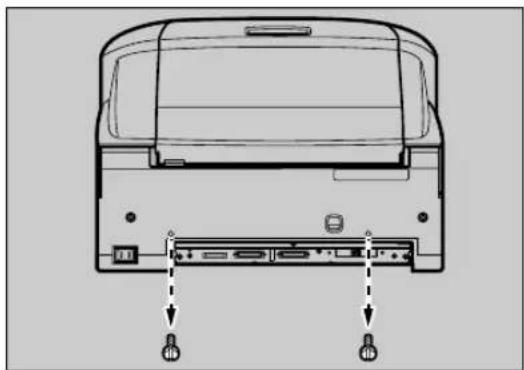
1 Remove two lock screws fixed on the back of this machine.
natural_image
Diagram of a printer rear panel with two ports and arrows indicating ports to the front panel (no text or labels present)ADC082S

Note
□Use a coin to remove the lock screws.
☐Be sure to remove the lock screws. Turning the power on without removing the screws could result not only in failure in scanning, but in malfunction of this machine.
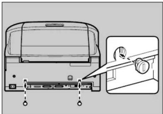
2 Cover both holes left by the removed screws with the caps.
①Put the leg stopper of the caps into the holes vertically.
natural_image
Diagram of a device rear panel with a close-up view showing a knob and adjustment knob (no text or symbols present)ADC084S
②Turn the caps 90 degrees.
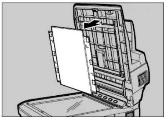
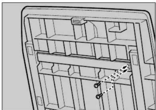
C The removed lock screws are to be kept on the back of the Pressure Panel as follows:
① Lift the Pressure Panel and carefully pull out the Background Panel that is fixed with the Velcro.
natural_image
Technical line drawing of a mechanical device with internal compartments and a door (no text or symbols)ADC071S
②The removed screws are to be kept fixing on the back of the Pressure Panel.
natural_image
Technical line drawing of a mechanical or electrical enclosure with shelves and doors (no text or symbols)ADC086S
③Return the removed Background Panel to where it was.
Reference
Regarding how to set the Background Panel, please refer to the step B - E of p.54 "Changing the Color of the Background Panel for the Exposure Glass".
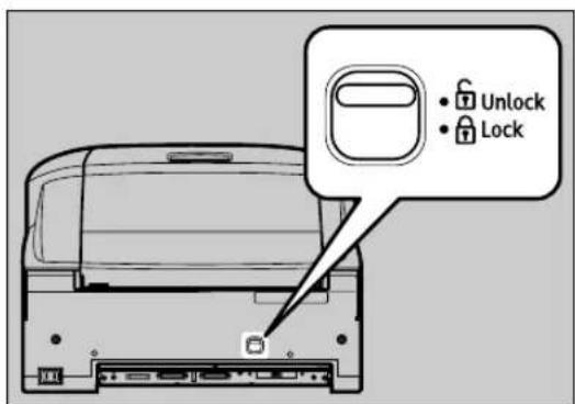
DTurn the lock lever on the back of this machine to the "Unlock" position.
ADC025S

Note
☐ Be sure to set the lock lever to the "Unlock" position. Turning the power on leaving the lock lever to the "Lock" position could result not only in failure in scanning but in malfunction of the machine.
Installing Options
Installing the Image-Processing Unit
Important
☐Touch any metallic material before touching the image-processing unit to remove static from your body.
Note
☐Use the accessory tool to remove or fix the screws.
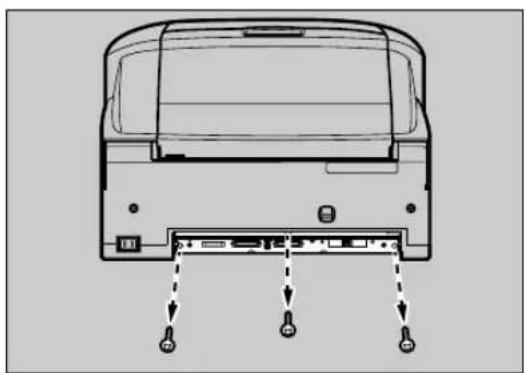
1 Turn OFF the power to this product and disconnect all cables connected to the product, including the power cable.
2 Remove the three screws on the lower back surface of the product.
natural_image
Diagram of a computer rear panel with ports and connectors, showing internal structure without any text or symbolsADC009S
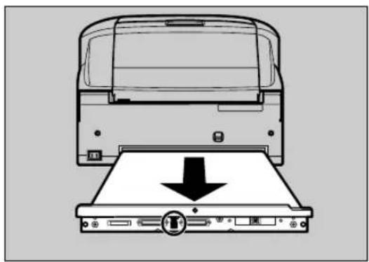
3 Pull out the scanner control unit by pulling the black ribbon on the center of the board.
natural_image
Diagram of a front view of a computer with an open drive and a downward arrow indicating download or compression (no text or symbols present)ADC010S
Important
☐The control unit is heavy. Please take care not to drop it when pulling it out.
4 Remove the seven screws on the cover of the scanner control unit.
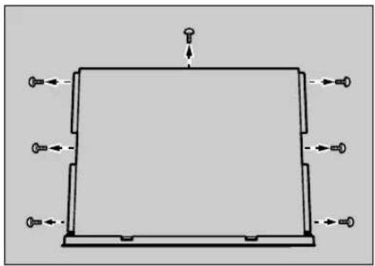
natural_image
Pure schematic diagram of a rectangular frame with directional arrows, no text or symbols presentADC064S
5 Open the cover of the scanner control unit.
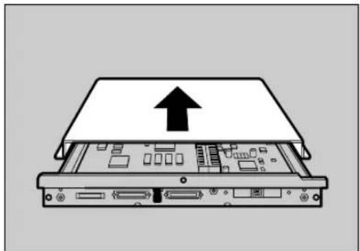
natural_image
Diagram of an open computer drive showing a top panel with an upward arrow and internal circuitry (no text or symbols)ADC0115
6 Connect the connector at the bottom surface of the image-processing unit to the connector of the scanner control unit, and fix with one accessory screw.
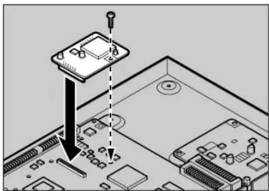
natural_image
Diagram showing a computer motherboard with an electronic component being inserted, no text or symbols presentADC012S
7 Check that it is connected tightly, check that there are no foreign objects such as metal on the scanner control unit.
8 Close the scanner control unit cover and fix with seven screws, then insert the scanner control unit into the main unit.
Note
□Be sure to place the scanner on the level surface when inserting the scanner control unit.
☐Insert the scanner control unit till you see the screw holes.
9 Fix the scanner control unit with three screws.
10 Removed cables must connect in former state.
Installing the IEEE1394 Interface Board
Important
☐Touch any metallic material before touching the IEEE interface board to remove static from your body.
Note
☐The optional IEEE 1394 interface board is alternatively used with the USB interface board.
1 Turn OFF the power to this product and disconnect all cables connected to the product, including the power cable.
2 Remove the three screws on the lower back surface of the product.
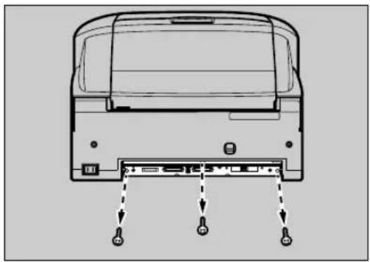
natural_image
Diagram of a rear view of a computer with ports and connectors, showing no text or symbolsADC009S
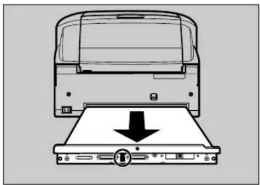
3 Pull out the scanner control unit by pulling the black ribbon on the center of the board.
natural_image
Diagram of a printer front view showing a printer with a downward arrow indicating compression or disassembly (no text or symbols present)ADC010S
Important
☐The control unit is heavy. Please take care not to drop it when pulling it out.
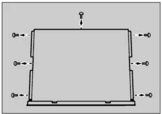
4 Remove the seven screws on the cover of the scanner control unit.
natural_image
Pure diagram of a rectangular frame with directional arrows and a small top component, no text or symbols present.ADC064S
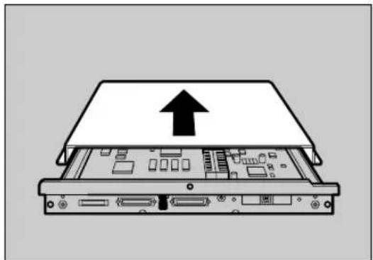
5 Open the cover of the scanner control unit.
natural_image
Diagram of an open computer drive showing a top portion with an upward arrow and internal circuitry (no text or symbols)ADC0115
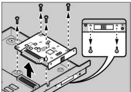
6 Remove the USB 2.0 interface board fixed with 6 screws.
ADC077S

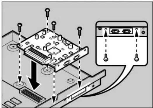
7 Connect the IEEE1394 interface board to the extension connector. Fix the board with four accessory screws from inside, two accessory screws from outside.
ADC014S
8 Check that it is connected tightly, check that there are no foreign objects such as metal on the scanner control unit.
9 Close the scanner control unit cover and fix with seven screws, then insert the scanner control unit into the main unit.
Note
☐Be sure to place the scanner on the level surface when inserting the scanner control unit.
☐Insert the scanner control unit till you see the screw holes.
10 Fix the scanner control unit with three screws.
11 Removed cables must connect in former state.
Connecting to the Computer
This scanner can be connected to the computer with either a SCSI, USB, or IEEE1394 interface. An optional board will be required to connect with IEEE1394.
Important
☐ Do not turn the power of the scanner ON before the software installation. If you run the "Found New Hardware Wizard" beforehand, you will not be able to install the software correctly. When the "Found New Hardware Wizard" started before the installation, click the [Cancel] button to discontinue the wizard.
Connecting with SCSI Interface
Standard, you can connect the scanner to two computers at the same time. One with the SCSI interface, and one with the USB 2.0 interface. Though, you cannot use the scanner at the same time from two computers. Interfaces are switched automatically when you change from one of the computer to the other.
When the IEEE1394 interface board of the option is installed, you can connect the scanner to three computers at the same time. One with a SCSI interface, and two with the optional IEEE1394 interface. Though, you cannot use the scanner at the same time from three computers. Interfaces are switched automatically when you use any one of the computers.
About the SCSI Interface
Connection of this scanner to the SCSI (Small Computer System Interface) is as follows:
- This scanner is compliant for SCSI-3. You can daisy chain with SCSI-1/2 compliant devices as well. The SCSI connector of this scanner is male 50pin half-pitch pin type. Use the shielded SCSI-2/3 cable compliant with ANSI (American National Standard Institute). Confirm in advance that some combination of the SCSI cable and SCSI board on the computer may cause an incorrect scanner operation.
- This scanner is compliant for SCAM (SCSI Configured Automatically). If you use SCAM corresponding to SCSI board and driver for your computer, the SCSI ID will be set automatically. p.23 "Setting the SCSI ID Automatically"
- This scanner has a built-in terminator. Set the DIP switches properly when you connect the scanner with the SCSI interface.
Important
☐ Using other cable than ANSI compliant SCSI-2/3 shielded cable, may possibly bring about malfunction or electromagnetic wave interference above VCCI rules.
☐ Connect a SCSI cable shorter than 4.9 feet (1.5m) for the SCSI-3 (Ultra-SCSI), and a 9.8 feet (3m) cable for the SCSI-2, including the cable length inside your computer.
☐Some combinations of the SCSI board of your PC and daisy-chained peripherals might cause an incorrect operation. Please contact and ask your service representative about the recommended SCSI board.
Setting the SCSI ID
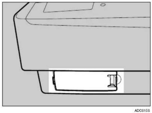
1 Open the cover of the switch box on the lower left of the frontside of the scanner.
natural_image
Technical line drawing of a printer or printer with a base and clasp (no text or symbols)Note
☐Push the knob of the cover to the left and pull the cover to open.
2 Confirm the DIP Switch No.1 to the OFF position.
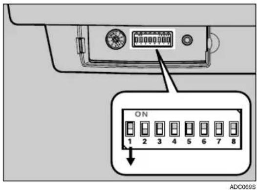
SCAM function is disabled.
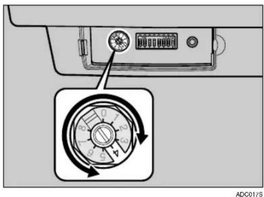
3 Set the SCSI ID by rotating the Rotary Switch.
Note
☐Press the Hard Reset Switch if you changed the SCSI ID while the power is ON. p.34 "Using the Hard Reset Switch"
Setting the SCSI ID Automatically
Note
☐If you use the SCSI board without SCAM function or the SCSI ID is overlapping with the other SCSI device, set the SCSI ID manually.
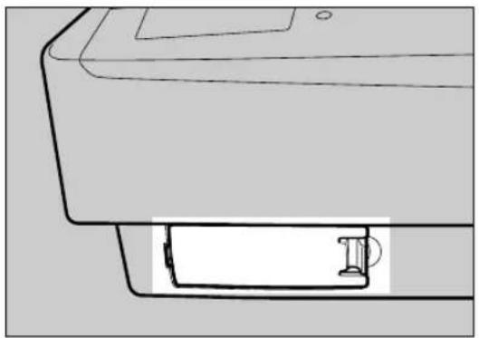
1 Open the cover of the switch box on the lower left of the frontside of the scanner.
natural_image
Line drawing of a printer with a base and paper holder (no text or symbols)ADC0153
Note
☐Push the knob of the cover to the left and pull the cover to open.
2 Set the DIP Switch No.1 to the ON position.
ADC016S
SCAM function is enabled.
Connecting the SCSI Cable (When the Scanner is at the End of the Daisy Chain)
1 Shut down the computer and all of the SCSI connected devices.
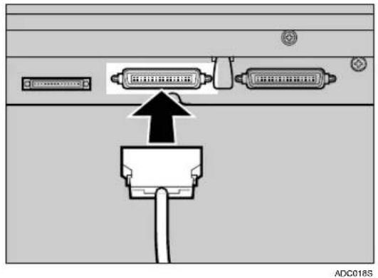
2 Daisy chain the computer, scanner and SCSI connected devices.
Note
☐Connect the SCSI cable to either one side of the connectors.
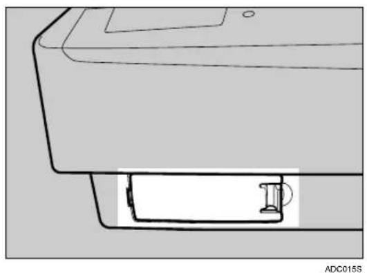
3 Open the cover of the switch box on the lower left of the frontside of the scanner.
natural_image
Technical line drawing of a printer or printer with a base and mounting bracket (no text or symbols)Note
☐Push the knob of the cover to the left and pull the cover to open.
4 Set the DIP Switch No.3 to the OFF position.
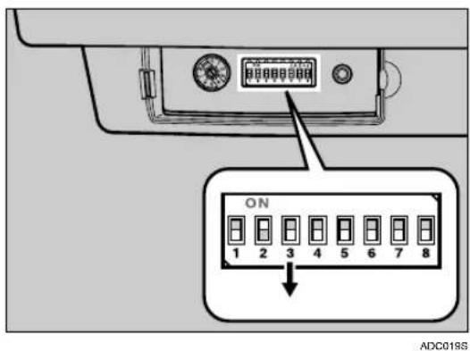
Built-in SCSI terminator is enabled.

Note
☐Press the Hard Reset Switch if you changed the SCSI ID while the power is ON. p.34 “Using the Hard Reset Switch”
2
Connecting the SCSI Cable (When the Scanner is not at the End of the Daisy Chain)
1 Shut down the computer and all of the SCSI connected devices.
2 Daisy chain the computer, scanner and SCSI connected devices.
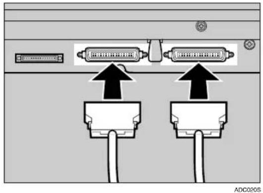
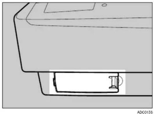
3 Open the cover of the switch box on the lower left of the frontside of the scanner.
natural_image
Technical line drawing of a printer or printer component with a base and mounting bracket (no text or symbols)Note
☐Push the knob of the cover to the left and pull the cover to open.
4 Set the DIP Switch No.3 to the ON position.
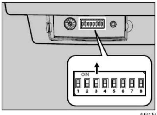
Built-in SCSI terminator is disabled.

Note
☐Press the Hard Reset Switch if you changed the SCSI ID while the power is ON.⇒ p.34 "Using the Hard Reset Switch"
Using the Scanner only with the SCSI Connection
You can set the scanner to the SCSI synchronous transmission for high-speed data transfer and shorten the total scan time. The USB and the optional IEEE1394 connection cannot be used when the SCSI synchronous transmission is set.
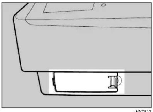
AOpen the cover of the switch box on the lower left of the frontside of the scanner.
natural_image
Technical line drawing of a printer or printer with a base and clasp (no text or symbols)
Note
☐Push the knob of the cover to the left and pull the cover to open.
B Set the DIP Switch No.2 to the OFF position.
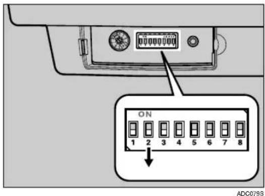
SCSI synchronous transmission is enabled.

Note
☐Press the Hard Reset Switch if you changed the DIP Switch while the power is ON. p.34 "Using the Hard Reset Switch"
Connecting with USB Interface
Note
☐Please use the recommended USB cable. Using other cables might occur an irregular operation. As for the recommended cables, please ask your service representative.
☐You can connect the scanner to two computers at the same time. One with the SCSI interface, and one with the USB 2.0 interface. Though, you cannot use the scanner at the same time from two computers. Interfaces are switched automatically when you change from one of the computer to the other.
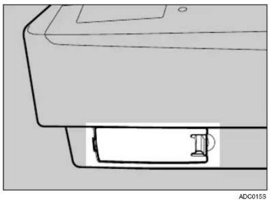
1 Open the cover of the switch box on the lower left of the frontside of the scanner.
natural_image
Technical line drawing of a printer or printer component with a base and mounting bracket (no text or symbols)Note
☐Push the knob of the cover to the left and pull the cover to open.
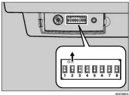
2 Confirm the DIP Switch No.2 is in the ON position.
Note
☐If the DIP Switch No.2 is set to OFF, set it to ON. If the switch is set to OFF, "Found New Hardware Wizard" will not start.
☐Press the Hard Reset Switch if you changed the DIP Switch while the power is ON. p.34 "Using the Hard Reset Switch"
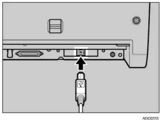
3 Connect the USB cable to the USB connector.
natural_image
Diagram of a computer interface showing an inserted cable connected to a port with an attached USB port (no text or symbols visible)4 Connect the other side of the cable to the USB connector on your computer.
Connecting with IEEE1394 Interface
Note
☐The optional IEEE1394 interface board is required.
☐An IEEE1394 cable is packed to be used for the optional IEEE1394 interface board.
☐An irregular operation might occur for the IEEE1394 interface board of some PC. Please use the recommended IEEE1394 interface board for your PC. As for the recommended boards, please ask you service representative.
☐You can connect the scanner to three computers at the same time. One with a SCSI interface, and two with the optional IEEE1394 interface. Though, you cannot use the scanner at the same time from three computers. Interfaces are switched automatically when you use any one of the computers.
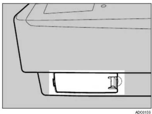
1 Open the cover of the switch box on the lower left of the frontside of the scanner.
natural_image
Technical line drawing of a printer or printer with a base and clasp (no text or symbols)Note
☐Push the knob of the cover to the left and pull the cover to open.
2 Confirm the DIP Switch No.2 is in the ON position.
ADC080S
Note
☐If the DIP Switch No.2 is set to OFF, set it to ON. If the switch is set to OFF, "Found New Hardware Wizard" will not start.
☐Press the Hard Reset Switch if you changed the DIP Switch while the power is ON. p.34 "Using the Hard Reset Switch"
3 Connect the IEEE1394 cable to the IEEE1394 connector.
ADC023S
Note
☐Connect the cable to either one of the connectors.
4 Connect the other side of the cable to the IEEE1394 connector on your computer.
5 Repeat Steps 3 and 4 with the other IEEE1394 connector to connect with a second computer.
Connecting to a Power Source
This section explains how to connect this machine to a power source, using a bundled AC power cord.
⚠ WARNING:
- Do not use with a power source with a voltage different from the specified voltage. Do not use a power outlet with multiple devices plugged in. These could create the risk of fire or electric shock.
- Avoid the use of an extension cord.
- Do not damage, break, twist or modify the Power Cord. Placing heavy objects on the cord, pulling on or bending it excessively can damage the Power Cord, creating the risk of fire or electric shock.
- Never touch or unplug the power plug with wet hands. This can create the risk of electric shock.
CAUTION:
- When unplugging from an outlet, be sure to grasp the plug when pulling. Never pull on the cord. This could damage the cord creating the risk of fire or electrical shock.
1 Confirm that the power switch is set to Off.
ADC124S
2 Confirm the lock screws on the back of this machine are removed and the holes left by the removed screws are covered with the caps.
ADC088S

Important
☐Be sure to remove the lock screws. Turning the power on without removing the screws could result not only in failure in scanning but in malfunction of this machine.

Confirm that the lock lever located on the back of the machine is set to the "Unlock" position.
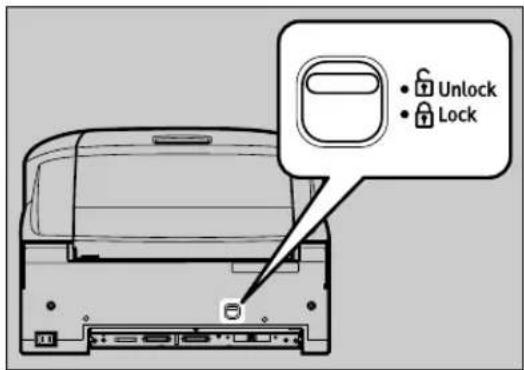
ADC025S

Important
☐ Be sure to set the lock lever to "Unlock". Turning on the power with the lock lever set to "Lock" could result in failure in scanning or in malfunction of this machine.

Push the power cord plug all the way into the power connector on this machine.
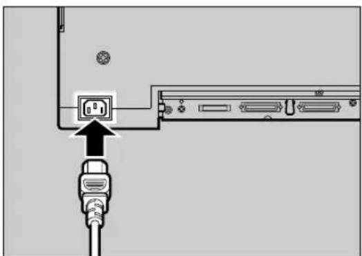
ADC026S

Note
□Be sure to use the power cord that comes with this machine.

Insert the power plug into the power outlet.
Turning the Power On/Off
Important
☐Do not turn the power of the scanner ON before the software installation. If you run the “Found New Hardware Wizard” beforehand, you will not be able to install the software correctly. When the “Found New Hardware Wizard” started before the installation, click the [Cancel] button to discontinue the wizard.

ADC101S
1.Power Off
2.Power On
Turning the Power On when Connected with SCSI Interface
Turn the power on from the farthest devices from the computer on the daisy chain. Start the computer last.
Note
☐The scanner will not be detected if you start the computer first.
Turning the Power On when Connected with USB/IEEE1394 Interface
There is no order to turn on the power when you connect the scanner with USB or IEEE1394 interface. You can turn on either the scanner or the computer first.
Turning the Power Off
There is no order to turn off the power. You can turn off either the scanner or the computer first.
Using the Hard Reset Switch
You need to hard reset the scanner when validate the settings of the DIP Switches or the Rotary Switch. To hard reset the scanner, you can turn off the scanner and turn it on again, or follow the procedures below.
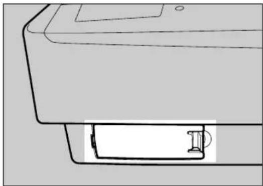
1 Open the cover of the switch box on the lower left of the frontside of the scanner.
natural_image
Line drawing of a printer with a base and clasp (no text or symbols)ADC015S
Note
□Push the knob of the cover to the left and pull the cover to open.
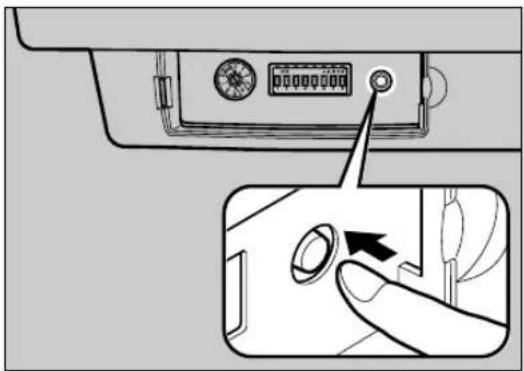
2 Press the Hard Reset Switch.
ADC0295
The scanner will be in the same status as when you turn off the scanner and turn it on again.
3. Installing Software
This machine can be used both as a TWAIN scanner and an ISIS scanner. A TWAIN driver and its applications are to be installed for the TWAIN scanner, and an ISIS driver and its applications are to be installed for the ISIS scanner.
Installing TWAIN Driver
When this machine is used as the TWAIN scanner; it is necessary to install the TWAIN driver to be used for the TWAIN compliant applications.

Preparation
Start installation, retaining the power of the scanner OFF.
System Requirements
Install TWAIN Driver to the computer that meets the system requirements below.
(A “recommended” environment is for scanning documents by 16,770K Full color Mode.)
- Hardware
PC/AT compatible
• CPU Pentium 200 MHz or faster (Pentium II 350 MHz or faster recommended)
• Memory 64 MB or more (128 MB or more recommended) - Hard Disk Space 200 MB or more (1GB or more recommended)
- Display Resolution 800 × 600 pixels, 256 colors or higher (16,770K colors or higher recommended)
- Operating Systems Windows 95(OSR 2 or later)/98/98 SE/Me/2000(Service Pack 4 or later)/XP, Windows NT 4.0 (Service Pack 5 or later), Windows Server 2003
Installing TWAIN Driver
Preparation
Log on to the computer as a member of the Administrators group, for installation to Windows 2000/XP, Windows Server 2003, or Windows NT 4.0.
1 Start the computer, retaining the power of the scanner OFF.
Note
☐If the power of the computer turns ON, retaining the power of the scanner ON, before driver installation, the "Found New Hardware Wizard" automatically starts. In this case, click [Cancel] button.
2 Start Windows, and then insert the supplied CD-ROM labeled "Scanner Driver(s), Utilities and Operating Instructions" into the CD-ROM drive of the client computer.
The CD-ROM Launcher screen appears.
When installation does not start automatically
Auto Run might not automatically work with certain operating system settings.
① Launch "Setup.exe" located in the CD-ROM root directory.
3 Click [TWAIN DRIVER].
The installer of the TWAIN driver starts. Follow the instructions on the screen.
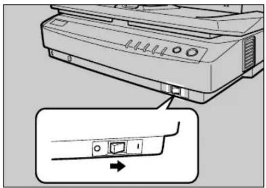
4 Turn the power of the scanner ON.
natural_image
Diagram of a printer with a close-up view showing internal components (no text or symbols)ADC125S
5 Re-start the computer.
The installation completes here for the computer with the operation systems, Windows 95 and Windows NT4.0. For the computer with other operation systems, "Plug & Play" detects the scanner and the "Found New Hardware Wizard" automatically starts.
6 In the Wizard, select [Search for a suitable driver for my device [recommended]], and continue the "Found New Hardware Wizard" to the end, according to the instruction on the display.
Note
☐When an instruction to set the Windows system CD-ROM appears on the display in the course of the installation, follow the instruction accordingly.
□Even when "No approval of the logo test" appears on the display, you can continue the installation by clicking [Continue].
About TWAIN driver help
After you have installed the TWAIN driver, [(Model Name) TWAIN V4] will be created under [Programs] of the [Start] menu. Help files for the TWAIN driver can be displayed from here.
Notes on using the TWAIN scanner are provided in "Readme.txt". Be sure to read them before use.
Changing the connecting interface
When you change the connecting interface from the interface first installed, change the cable to the new interface and start from step 4. "Scanner Driver(s), Utilities and Operating Instructions" CD-ROM is not required.
Note
☐Please confirm the DIP Switch when you connect each cable.
Installing DeskTopBinder Lite
DeskTopBinder Lite is a software with which you can manage various types of file data, such as scanned images, or documents as if they were one file. This software is compatible with a TWAIN driver. You can use this software to scan documents with this scanner.
System Requirements
Install DeskTopBinder Lite to the computer that meets the system requirements below.
- Hardware
PC/AT compatible - CPU
Pentium 133 MHz or faster (Pentium II 266 MHz or faster recommended) - Memory
48 MB or more (128 MB or more recommended) - Hard Disk Space
Minimum free space required for installing: 70 MB

Note
☐In addition to the space required for installation, the hard disk should have at least 200 MB of free space for files.
- Operating Systems
Windows 98 SE/Me/2000(Service Pack 1 or later)/XP, Windows Server 2003
Installing DeskTopBinder Lite
Preparation
Log on to the computer as a member of the Administrators group, for installation to Windows 2000/XP, or Windows Server 2003.
1 Start Windows, and then insert the supplied CD-ROM labeled "Scanner Driver(s), Utilities and Operating Instructions" into the CD-ROM drive of the client computer.
The CD-ROM Launcher screen appears.
When installation does not start automatically
Auto Run might not automatically work with certain operating system settings.
① Launch "Setup.exe" located in the CD-ROM root directory.
2 Click [DeskTopBinder Lite.]
The DeskTopBinder Lite Setup screen appears.
3 Click [DeskTopBinder Lite].
The Installer of the DeskTopBinder Lite starts. Follow the instructions on the screen.
Reference
For information about the subsequent installation procedure, see the Setup Guide which can be displayed from the Setup screen of DeskTopBinder Lite.
Installing ISIS Driver
When this machine is used as the ISIS scanner; it is necessary to install the ISIS driver to be used for the ISIS compliant applications.

Preparation
Start installation, retaining the power of the scanner OFF.
System Requirements
Install ISIS Driver to the computer that meets the system requirements below.
- Hardware
PC/AT compatible - Display Resolution
1024 × 768 pixels, 256 colors or higher (16,770K colors or higher recommended) - Operating Systems
Windows 98/98 SE/Me/2000(Service Pack 4 or later)/XP, Windows NT 4.0 (Service Pack 6 or higher)
Installing ISIS Driver
Preparation
Log on to the computer as a member of the Administrators group, for installation to Windows 2000/XP, Windows Server 2003, or Windows NT 4.0.
1 Start the computer, retaining the power of the scanner OFF.
Note
☐If the power of the computer turns ON, retaining the power of the scanner ON, before driver installation, the "Found New Hardware Wizard" automatically starts. In this case, click [Cancel] button.
2 Start Windows, and then insert the supplied CD-ROM labeled "Scanner Driver(s), Utilities and Operating Instructions" into the CD-ROM drive of the client computer.
The CD-ROM Launcher screen appears.
When installation does not start automatically
Auto Run might not automatically work with certain operating system settings.
① Launch "Setup.exe" located in the CD-ROM root directory.
3 Click [ISIS DRIVER].
The installer of the ISIS driver starts. Follow the instructions on the screen.
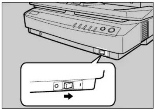
4 Turn the power of the scanner ON.
natural_image
Diagram of a printer with a close-up view showing the internal component (no text or symbols present)ADC125S
5 Re-start the computer.
The installation completes here for the computer with the operation systems, Windows 95 and Windows NT4.0. For the computer with other operation systems, "Plug & Play" detects the scanner and the "Found New Hardware Wizard" automatically starts.
6 In the Wizard, select [Search for a suitable driver for my device [recommended]], and continue the "Found New Hardware Wizard" to the end, according to the instruction on the display.
Note
☐When an instruction to set the Windows system CD-ROM appears on the display in the course of the installation, follow the instruction accordingly.
□Even when "No approval of the logo test" appears on the display, you can continue the installation by clicking [Continue].
Changing the connecting interface
When you change the connecting interface from the interface first installed, change the cable to the new interface and start from step 4. "Scanner Driver(s), Utilities and Operating Instructions" CD-ROM is not required.
Note
☐Please confirm the DIP Switch when you connect each cable.
Installing QuickScan
This software is compatible with a ISIS driver. You can use this software to scan documents with this scanner.
System Requirements
Install QuickScan to the computer that meets the system requirements below.
- Hardware
PC/AT compatible
• CPU
Pentium II or faster (Pentium II 400 MHz or faster recommended) - Memory
64 MB or more (128 MB or more recommended) - Hard Disk Space
Minimum free space required for installing: 200 MB - Operating Systems
Windows 98/98 SE/Me/2000(Service Pack 4 or later)/XP
Installing QuickScan

Preparation
Log on to the computer as a member of the Administrators group, for installation to Windows 2000/XP, or Windows Server 2003.

Start Windows, and then insert the supplied CD-ROM labeled "Scanner Driver(s), Utilities and Operating Instructions" into the CD-ROM drive of the client computer.
The CD-ROM Launcher screen appears.
When installation does not start automatically
Auto Run might not automatically work with certain operating system settings.
① Launch "Setup.exe" located in the CD-ROM root directory.

Click [QuickScan].
The Installer of the QuickScan starts. Follow the instructions on the screen.

Reference
For information about the subsequent installation procedure, see the Setup Guide which can be displayed from the Setup screen of QuickScan.
Installing Software
4. Setting Originals
This chapter describes how to set an original to be scanned with this machine. It is possible to set an original on the exposure glass or the ADF. To scan several pages successively, using the ADF is convenient.
Sizes and Weights of Recommended Originals
| Where original is set | Original size (Main scanning × Sub scanning) Original weight | |
| Exposure glass | Up to 12" × 17" Up to 297mm × 432mm | — |
| ADF | Standard sizeMaximum: 11" × 17", A3Minimum: B6JIS (Japanese Industrial Standard)Non-standard sizeOne side colorMaximum: 12" (297mm) × 24.8" (630mm)Minimum: 2.7" (69mm) × 3.5" (90mm)One side monochromeMaximum: 12" (297mm) × 78.7" (2000mm)Minimum: 2.7" (69mm) × 3.5" (90mm)Both side color, Both side monochrome (The duplex model machine only)Maximum: 12" (297mm) × 17" (432mm)Minimum: 2.7" (69mm) × 3.5" (90mm) | 40-157g/m2(77-298lbs) |
Note
☐ When you scan the thick originals — originals thicker than 128g/m^2 (242.5bls) — with the ADF, set the paper thickness changeover lever to your side. After scanning, return the lever to the back side.
☐It may not be possible to scan a full color original even if it meets requirements of the chart above. See “Readme.txt” in the CD-ROM for details.
Original Sizes Available for Auto Detection
The scanner can detect the following document sizes automatically.
When the Background Panel is Black
All of the original size can be detected from Exposure glass and ADF.
When the Background Panel is White
- When set on the Exposure glass Unable to detect automatically.
- When set on the ADF
$$ \begin{array}{l} 1 1 ^ {\prime \prime} \times 1 7 ^ {\prime \prime} (2 7 9 \mathrm{mm} \times 4 3 2 \mathrm{mm}) \ 8 ^ {1} / _ {2} ^ {\prime \prime} \times 1 4 ^ {\prime \prime} (\text {Legal}, 2 1 6 \mathrm{mm} \times 3 5 6 \mathrm{mm}) \ 8 ^ {1} / _ {2} ^ {\prime \prime} \times 1 3 ^ {\prime \prime} (2 1 6 \mathrm{mm} \times 3 3 0 \mathrm{mm}) \ 8 ^ {1} / _ {2} ^ {\prime \prime} \times 1 1 ^ {\prime \prime} (\text {Letter}, 2 1 6 \mathrm{mm} \times 2 7 9 \mathrm{mm}) \ 8 ^ {1} / _ {2} ^ {\prime \prime} \times 1 1 ^ {\prime \prime} (\text {Letter}, 2 7 9 \mathrm{mm} \times 2 1 6 \mathrm{mm}) \ 5 ^ {1} / _ {2} ^ {\prime \prime} \times 8 ^ {1} / _ {2} ^ {\prime \prime} (2 1 6 \mathrm{mm} \times 2 7 9 \mathrm{mm}) \ 5 ^ {1} / _ {2} ^ {\prime \prime} \times 8 ^ {1} / _ {2} ^ {\prime \prime} (2 1 6 \mathrm{mm} \times 2 7 9 \mathrm{mm}) \ \end{array} $$
$$ \mathrm{A} 3 \left(1 1. 7 ^ {\prime \prime} \times 1 6. 5 ^ {\prime \prime}, 2 9 7 \mathrm{mm} \times 4 2 0 \mathrm{mm}\right) \text {口} $$
$$ \mathrm{B4JIS} \left(1 0 ^ {\prime \prime} \times 1 4. 3 ^ {\prime \prime}, 2 5 7 \mathrm{mm} \times 3 6 4 \mathrm{mm}\right) \text {口} $$
$$ \mathrm{A} 4 \left(8. 3 ^ {\prime \prime} \times 1 1. 7 ^ {\prime \prime}, 2 1 0 \mathrm{mm} \times 2 9 7 \mathrm{mm}\right) \text {口} $$
$$ \mathrm{A} 4 \left(8. 3 ^ {\prime \prime} \times 1 1. 7 ^ {\prime \prime}, 2 1 0 \mathrm{mm} \times 2 9 7 \mathrm{mm}\right) \text { 口 } $$
$$ \mathrm{B5JIS} \left(7. 2 ^ {\prime \prime} \times 1 0 ^ {\prime \prime}, 1 8 2 \mathrm{mm} \times 2 5 7 \mathrm{mm}\right) \text {口} $$
$$ \mathrm{B5JIS} \left(7. 2 ^ {\prime \prime} \times 1 0 ^ {\prime \prime}, 1 8 2 \mathrm{mm} \times 2 5 7 \mathrm{mm}\right) ↳ $$
$$ \mathrm{A} 5 \left(8. 3 ^ {\prime \prime} \times 5. 8 ^ {\prime \prime}, 2 1 0 \mathrm{mm} \times 1 4 8 \mathrm{mm}\right) \text { 口 } $$
$$ \mathrm{B6JIS} (7. 2 ^ {\prime \prime} \times 5 ^ {\prime \prime}, 1 8 2 \mathrm{mm} \times 1 2 8 \mathrm{mm}) $$
Originals that Require Special Care
When scanning the following types of originals, be sure to follow the descriptions below.
◆Originals that are difficult to detect the size automatically
It is difficult for the scanner to automatically detect the sizes of the following types of originals, so select the original size manually.
• Originals with indexes, tags, or other protrusions
- Transparent originals such as OHP transparencies or translucent paper
• Text or picture dense original
• Originals containing solid images
• Originals containing solid images around their edges
◆Originals that cannot be set in the ADF
Placing the following types of originals in the ADF can cause paper misfeeds or result in damage to the originals. Place these originals on the exposure glass instead.
- Stapled or clipped originals
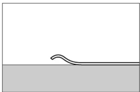
• Perforated or torn originals - Curled, folded, or creased originals
- Pasted Originals
- Originals with any kind of coating, such as thermal fax paper, art paper, aluminum foil, carbon paper, or conductive paper
• Originals with perforated lines - Originals with indexes, tags, or other projecting parts
- The originals with large frictional resistance such as non-carbon papers.
- Sticky originals such as translucent paper
- Thin originals that have low stiffness
- Bound originals such as books
- Transparent originals such as OHP transparencies
• Originals with ink or correction liquid on them and still not completely dry
• Originals with large curl on the end
natural_image
Simple line drawing of a wavy line above a horizontal line on a gray surface (no text or symbols)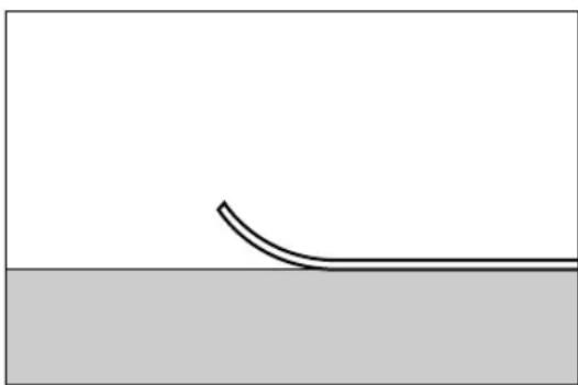
natural_image
Simple line drawing of a curved surface above a horizontal line, with no text or symbols present.ADC065S
Placing Originals
Placing the Original on the Exposure Glass
Important
☐Be careful not to pinch your fingers when closing the ADF.
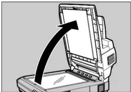
1 Lift the Pressure Panel.
natural_image
Illustration of a computer monitor with an upward arrow indicating growth or direction (no text or symbols present)ADC0305
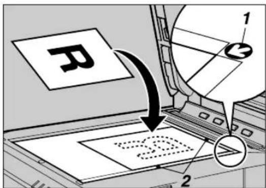
2 With the side to be scanned facing down, place the original on the exposure glass, and align it with the home position and scale.
ADC103S
1.Home position
2.Scale
Important
☐Do not press down on the exposure glass. Strong pressure on the exposure glass could cause it to break.
3 Gently lower the ADF.
Placing the Originals in the ADF
The ADF allows you to place multiple originals at one time.
◆Precautions when placing an original in the ADF
- For information about the originals that cannot be placed in the ADF, see p.47 "Originals that cannot be set in the ADF".
Important
☐ Attempting to use unsuitable originals in the ADF can lead to a misfeed and damage to the originals. Place such originals directly on the exposure glass.
- Do not set originals in the ADF in excess of the upper limit mark.
- In case the end of originals are curled too much to feed with the ADF, decrease the number of originals or adjust the curled end of originals straight.
- See p.46 "Original Sizes Available for Auto Detection" for information about the original sizes that can be detected automatically.
- Fan the originals to get air between the sheets before setting them in the ADF.
1 Adjust the stopper of the Output Table to the size of your originals.
ADC104S
1. stopper
Note
☐Pull out the stopper and insert it to the other way to adjust the position of the stopper when you are scanning originals shorter than 5.8'' × 8.3'' L or 4.1'' × 5.8'' K (A5L or A6K) in longways.

Important
☐Do not hold the stopper to open the ADF.
2 Align the originals. To have the originals scanned in order, set the originals in order illustrated below.
- Simplex scanning
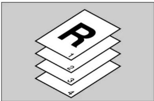
ADC0625
- Duplex scanning
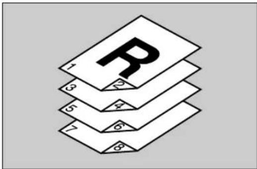
ADC063S
3 Fan the originals and align them well.
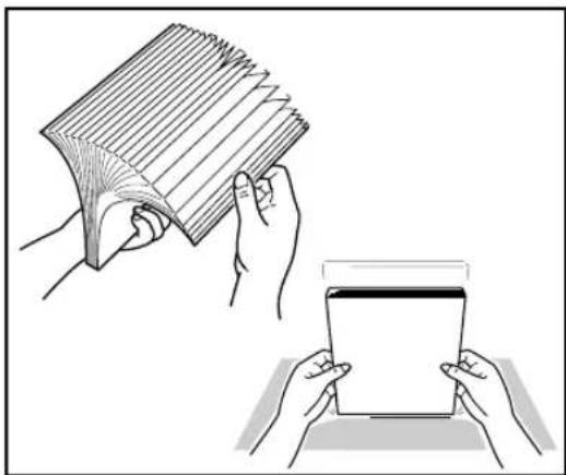
natural_image
Illustration showing hands holding a card and a tablet (no text or symbols present)4 Place the originals with first page on the top with the face up. Adjust the side guides to the size of your originals.
ADC105S
1.Side guides
Note
☐Adjust the original guide carefully by moving the root part of the original guide located over the original tray ditch.
□Be careful not to drop any alien objects such as paper clip, dust, etc. into the original tray ditch.
☐Check that the ADF is closed.
5 Set the paper thickness changeover lever to your side when you scan the thick originals — originals thicker than 128g/m^2 (242.5bls).
ADC078S
Note
□After scanning, return the switch to the back side.
Changing the Color of the Background Panel
Change the color of the Background Panel to enable auto original size detection or scan in clear images.
Important
☐ Change the settings of the TWAIN driver from [Back.Panel] tab in [Initial Settings] of the driver dialog.
☐Make sure that the color of the Background Panel for Exposure Glass, ADF and settings made in [Back.Panel] tab on the TWAIN driver are same.
Note
☐The size of the originals that can be automatically detected will be different depending on the color of the Background Panel. p.46 "Original Sizes Available for Auto Detection"
☐You can reduce the transparencies of the duplex printed originals by setting the Background Panel to Black.
☐To scan the transparent originals which is simplex printed, set the Background Panel to White.
Changing the Color of the Background Panel for the ADF
Preparation
Skip this procedure if you use the simplex scanner.
1 Lift the Pressure Panel.
2 Take off the Background Plate for Exposure Glass.
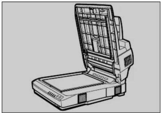
natural_image
Line drawing of a portable electronic device with open lid and internal grid structure (no text or symbols)ADC035S
Reference
⇒ p.54 "Changing the Color of the Background Panel for the Exposure Glass"
3 Turn down blue levers on both sides.
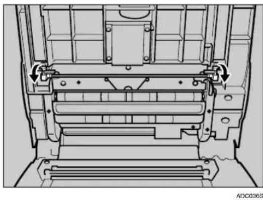
natural_image
Technical diagram of a mechanical assembly with arrows indicating directional components (no text or symbols)The unit which stores the Background Panel for the ADF is drawn out.
4 Push down a lever on the left, and change the color of the Background Panel by rotating the screw on the right to the △mark position.
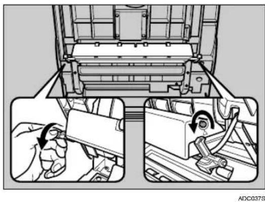
natural_image
Technical illustration of a mechanical assembly with two views showing tool positioning (no text or symbols)Note
Turn the slit in the way shown in the illustration. Do not turn to the other side.
☐Turn the slit till you hear the click. Rotate the screw to the position of the Δmark position, and confirm that the Background Panel color has totally changed.
5 Push back the unit which you drew out in step 3 by pushing both ends of the unit.
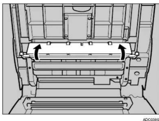
natural_image
Technical diagram of a mechanical assembly with no visible text or symbolsChanging the Color of the Background Panel for the Exposure Glass
Note
☐To change the color of the Background Panel for the Exposure Glass, reverse the panel.
1 Lift the Pressure Panel, and carefully pull out the Background panel that is fixed with magic tapes.
natural_image
Technical line drawing of a mechanical device with open lid and internal compartments (no text or symbols)ADC071S
2 Place the Background Panel on the Exposure Glass, with the color to use downside.
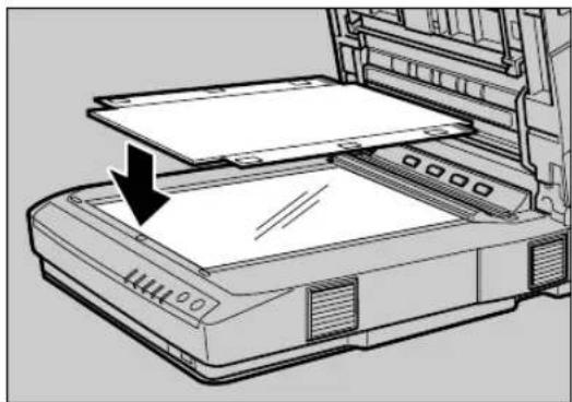
natural_image
Line drawing of a printer with an open lid and paper feed, showing internal structure without any text or symbols.ADC0725
Note
☐Set the Background Panel so as to align the blue line at the Home position.
C Align upper right of the Background Panel, with the home position for originals.
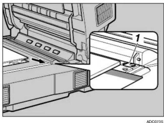
natural_image
Technical diagram of a printer or printer assembly with a close-up view of the component (no text or symbols visible)1.Home position
DClose the Pressure Panel slowly, and press it down firmly.
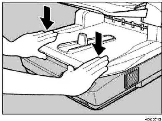
natural_image
Illustration of hands operating a printer with arrows indicating process flow (no text or symbols)E Lift the Pressure Panel again, and press all over the Pressure Panel with a clean, soft cloth.
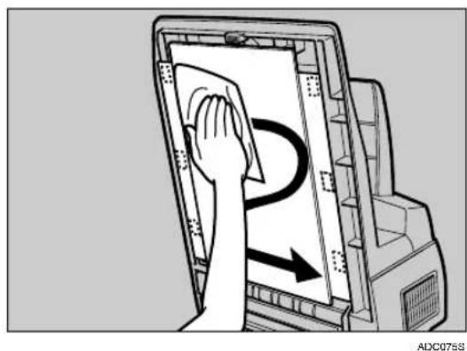
natural_image
Illustration of a hand cleaning a device with a curved arrow indicating motion (no text or symbols)4
5. Using the TWAIN Driver
This chapter describes the operations for scanning originals with the TWAIN driver using DeskTopBinder Lite. In addition, some functions of the TWAIN driver are introduced.
Procedure Breakdown
The following overview diagram shows the flow of the steps for scanning documents from a computer using the TWAIN driver.
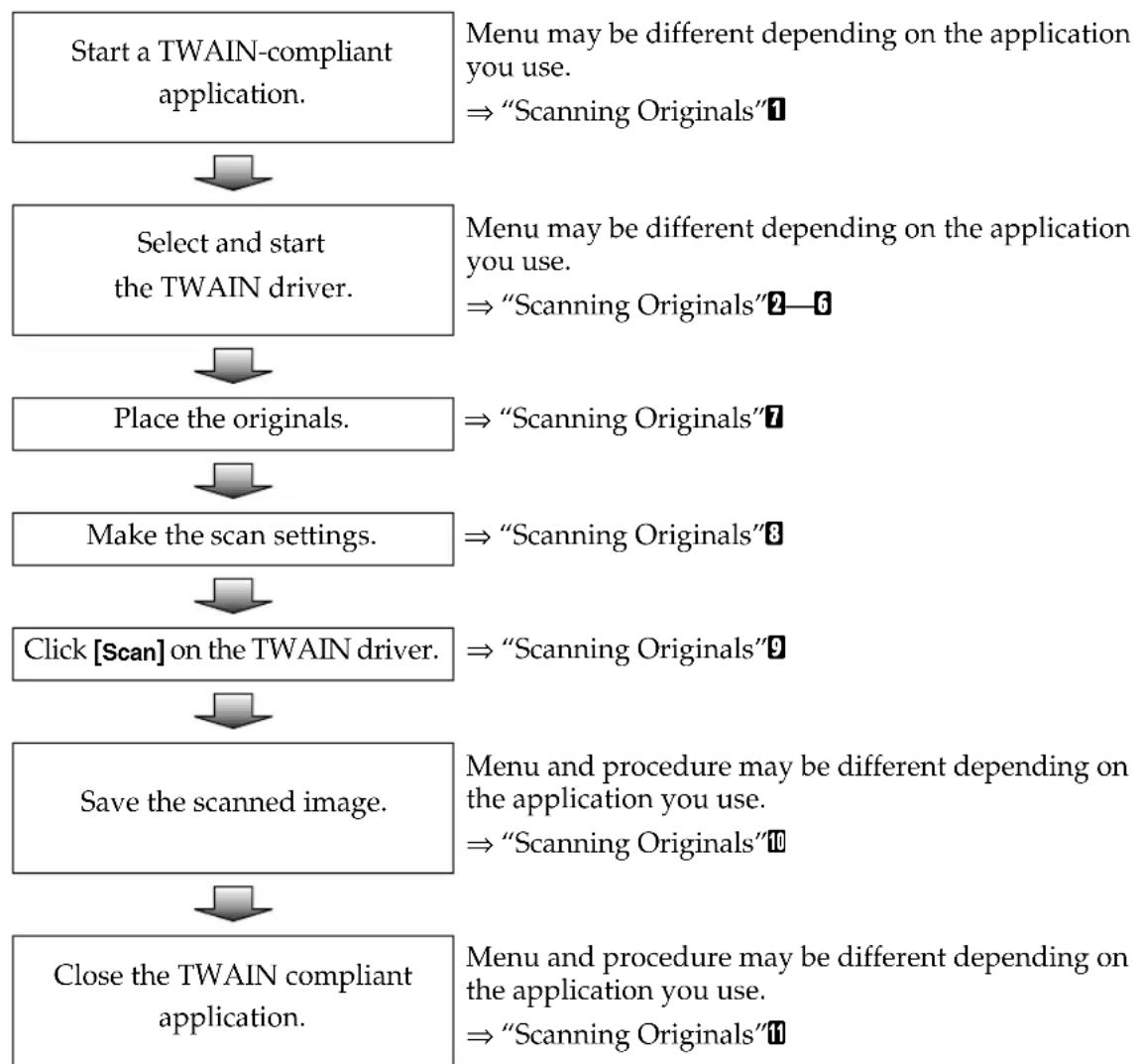
flowchart
graph TD
A["Start a TWAIN-compliant application."] --> B["Select and start the TWAIN driver."]
B --> C["Place the originals."]
C --> D["Make the scan settings."]
D --> E["Click [Scan"] on the TWAIN driver.]
E --> F["Save the scanned image."]
F --> G["Close the TWAIN compliant application."]
A --> H["Menu may be different depending on the application you use.<br>⇒ "Scanning Originals"1"]
B --> I["Menu may be different depending on the application you use.<br>⇒ "Scanning Originals"2—6"]
C --> J["⇒ "Scanning Originals"7"]
D --> K["⇒ "Scanning Originals"8"]
E --> L["⇒ "Scanning Originals"9"]
F --> M["Menu and procedure may be different depending on the application you use.<br>⇒ "Scanning Originals"10"]
G --> N["Menu and procedure may be different depending on the application you use.<br>⇒ "Scanning Originals"11"]
Scanning Originals
This section explains how to scan originals using the TWAIN scanner function. The procedure goes along with p.57 "Procedure Breakdown".
On the [Start] menu, point to [Program], point to [DeskTopBinder], and then click [DeskTopBinder].
DeskTopBinder Lite starts.
2 Click [Scanner Settings...] on the [Tools] menu.
[Scanner Settings] dialog box appears.
Note
☐ Check the settings in the [File format for scanned image(s)] area. Scanned data will be saved by the format specified here.
3 Click [Select Scanner Driver...].
The name of the scanner you installed with the TWAIN driver will be displayed in the [Source] list.
4 Select the model name and then click [Select...].
The TWAIN driver for the scanner is selected, and the [Source] list dialog box will be closed.
5 Click [OK] on the [Scanner Settings] dialog box.
The [Scanner Settings] dialog box closes.
6 On the [File] menu, point to [Add Document], and then click [Scan...].
After a short while, the dialog box of the TWAIN driver that operates the scanner appears.
7 Place the Originals.
Note
Place the originals either on the Exposure Glass or on the ADF. See p.48 "Placing Originals" for details.
8 Make the scan settings.
Note
☐View the TWAIN driver help files for the details of making the scan settings and the preview function.
9 Click [Scan...]
Note
☐ If you checked [Start from Scanner] on the TWAIN driver, press the [Start] key after you clicked [Scan...].
The image is scanned. It will be displayed in the DeskTopBinder Viewer and the TWAIN driver dialog will close.
Note
□With DeskTopBinder Lite, it is possible to edit and print scan files. For more information about how to edit and print, see DeskTopBinder Lite Help.
10 Save the scanned image in DeskTopBinder Lite.
① On the [File] menu, click [Exit].
② Enter the file name, and then click [OK].
The image is stored in DeskTopBinder Lite, and DeskTopBinder Viewer closes.
11 Close DeskTopBinder Lite.
① On the [File] menu, click [Exit].
DeskTopBinder Lite closes.
What You Can Do with the TWAIN Driver
The following is an introduction to the various functions of the TWAIN driver:

Reference
For more information about these functions or other functions, see TWAIN driver Help.
Functions of the TWAIN Driver
| Functions About | Explanation | |
| Scan Mode 4 Basic | modes(Standard/Photo/OCR/Filing),User saved 100 scan modes | You can call out and save the original Scan Modes. |
| Orientation: Standard | 0 deg./Right 90 deg./180 deg./Left 90 deg. | You can rotate the image to have originals scanned in correct orientation depending on the place to set the originals. If you are scanning the duplex printed originals, set the [Scan Settings:] as well. |
| Comb./Series Combine | 2 pages to 1/Combine 4 pages to 1/divide to 2 pages/Do not divide/No combination or division | You can divide two-page spread originals to two individual page images, or combine duplex printed originals to a simplex one page image. |
| 256 Colors(in [Col./Grad]) | ←Reduces 24bit color data to 8bit to make the data size smaller. | |
| Endorser User set characters/Date/Counter: | You can add the information mentioned in the left to the scanned images. You can change the size and the fonts of the endorser. | |
| ICM: (in[Color Matching]) | ←When you enable ICM, the TWAIN Driver will match the color data according to the color profile. | |
| Deskew ←Detects and corrects the tilt of the text strings. | ||
| Start from Scanner | ←Press the【 | 【Start】key of the scanner to start scanning the originals. |
| Preview ←You can confirm the settings you made for the scanning images before scanning the originals. | ||
| SADF ←Scanning starts when you set the originals on the ADF. When you are scanning the originals which are apt to be double fed, enable SADF and set the originals one by one on the ADF. | ||
| Functions About Explanation | ||
| Original Size | Auto detect(Mixed-size)/Auto detect(Uni-size)/Various fixed form sizes /Custom size | When the Background Panel is black, an optional width and length of originals will be automatically detected for both ADF and Exposure Glass by the [Auto detect(Mixed-size)] function. |
| Double Feed Detect | Ultrasonic Wave/Length/Ultrasonic Wave+Length/Off | While using ADF, it detects and notes a double feeding. A new ultrasonic function to check space between originals, in addition to the detection of original length, enables more reliable detection of the double feeding. |
5
6. Appendix
Troubleshooting
Error Indicators
The following table shows the meaning of error indicators of this machine, and how to fix the errors.
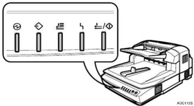
| Error description Solution | |||||
| ◎ | — | — | ◎ | — | The ADF or ADF cover is not fully closed. |
| ◎ | — | ◎ | ◎ | — | An original is jammed in the ADF.More than one sheet of originals are fed to the ADF simultaneously, or incorrect feeding occurs. |
| ○ | ○ | ○ | ○ | System error Contact your service representative. |
◎: On
O: Blinking
—: Off
Note
☐When the indicators show a status that is not listed above table, turn off the power of this machine, and then back on. If the indicators still show the same status, note the status of the indicators and contact your service representative.
When the Original is Jammed or Double Fed in the ADF
When the original jammed in or double fed to the ADF, remove the original by the following procedure.
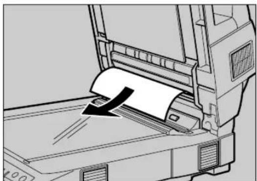
1 Open the ADF cover and remove if the original is jammed.
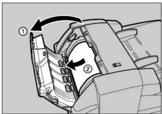
ADC046S
2 Remove the original if it is jammed in the cove of the Original Table.
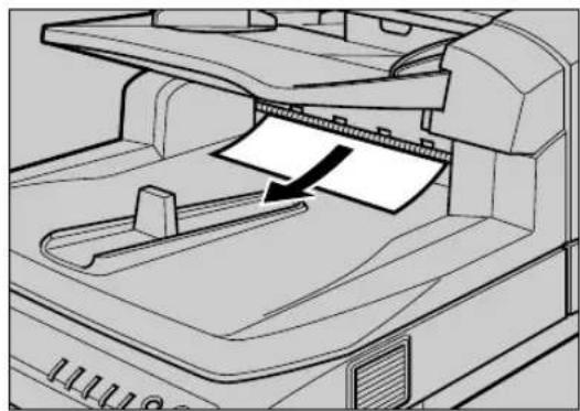
natural_image
Line drawing of a printer's internal structure showing paper feeding into a tray (no text or symbols)ADC047S
Note
☐You can easily remove the original by lifting the ADF a little.
3 Lift the ADF and remove if the original is jammed.
natural_image
Technical line drawing of a printer printer with paper feed and paper roll (no text or symbols)ADC066S
4 In case the jammed original is not found so far, follow the procedures below:
①Take off the Background Panel.
Reference
⇒ p.54 “Changing the Color of the Background Panel for the Exposure Glass”
②Turn down blue levers on both sides.
ADC036S
The unit which stores the Background Panel for the ADF is drawn out.
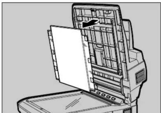
③Remove the jammed original.
ADC067S
Note
☐Regarding a small size original that cannot be set in the ADF, place it on the Exposure Glass instead. p.47 “Originals that cannot be set in the ADF”
When the Originals are Not Fed Correctly
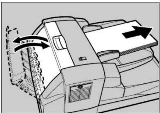
1 Remove the originals from the ADF.
2 Lift the Pressure Panel or open the ADF cover.
natural_image
Diagram of a printer with paper feed and paper roll, showing internal components and directional arrows (no text or symbols)ADC048S
Unusual conditions of the Original Table will be corrected.
3 Shutdown the Pressure Panel or the ADF cover.
Note
□When you shut the ADF cover, please confirm the two magnets are fixed on the magnet catch and the cover is closed tightly.
When Scanning is Not Performed as Expected
| Condition Possible Cause and Required Action | |
| The scanned image is dirty. | The Exposure Glass, the ADF Exposure Glass, Background panel, Feed roller or Original Roller is dirty.Clean the Exposure Glass, the ADF Exposure Glass, Background panel, Feed roller or Original Roller. ⇒ p.71 “Cleaning” |
| The originals are damaged when fed to the ADF. | Set the paper thickness changeover lever correctly or it may damage originals. Please confirm the lever and the paper thickness of the originals. When you scan the originals thicker than 128g/m ^2 (242.5bls), turn the changeover lever on your side (thick paper mode). |
| Image is distorted or out of position. | The original was moved while scanning.Do not move the original while scanning.The original was not pressed flat against the exposure glass. Make sure that the original is pressed flat against the exposure glass. |
| The scanned image is upside down. | The original was placed upside down. Place the original in the correct orientation, or set the [Orientation:] on the TWAIN driver to the correct setting. |
| No image results from scanning. | The original was placed with the front and back reversed.When the original is placed directly on the exposure glass, the side to be scanned must face down. When the original is fed via the ADF, the side to be scanned must face up. |
| When the Background Panel is white, the scanning size will be 0.1inch longer than the actual original size. | Change the [Original Size:] to the standard size from the automatic detection setting.When the original is a non-standard size, please specify the original size by use of the [Basic] tubChange background color to black, and you can detect the same size of originals. Please use black background for the mixed-size in particular. |
When an Error Message Appears
| Message Possible | Cause Required Action | |
| Cannot find the scanner.Check if the scanner main power is on. | The TWAIN driver cannot find the scanner.When using SCSI, you have the computer started before turning on the scanner.It is set to SCSI synchronous transfer mode. Use the scanner with SCSI asynchronous transmission mode when you use the USB/IEEE1394 connection. | Check the cables and connectors to see if it is connected correctly.Check the power source of the scanner.When using SCSI, turn on the power from the farthest device on the SCSI daisy chain. Start the computer last.Set the DIP Switch No.2 to ON and push the Hard Reset Switch in the switch box when you use the USB or IEEE1394 connection. |
| Scanner is not ready.Check the scanner and the options. | The scanner is busy initializing, or etc.The ADF cover is open.The ADF is lifted. | Wait for a while after turning on the power of the scanner till it gets ready.Check the ADF. |
| Fatal error has occurred in the scanner. | Hardware errors from which recovery is impossible have occurred in the scanner. | Note the error message and error number and call the service representative. |
Message Possible Cause Required Action
| Error has occurred in the scanner. | There is an error in parameter setting to the scanner. | Reinstall the TWAIN driver.If the same error occurs again, please call the service representative. |
| Error has occurred in the scanner driver. | There is an error in the driver, scanner, or in the operating system. | Restart the operating system.If the same error occurs again, please call the service representative. |
| Required library module cannot be found.Please reinstall the module. | The library module has not been found. | Reinstall the TWAIN driver. |
| Insufficient memory.Close all other applications, then restart scanning. | The memory or the virtual memory on your computer is short. | Close applications unnecessary for scanning.Expand the memory or the virtual memory of your computer. |
| Clear Misfeed(s) in ADF. | The misfed original is jammed inside the ADF. | Remove the misfed originals and scan again. ⇒ p.64 “When the Original is Jammed or Double Fed in the ADF”Remove the misfed originals and clear the error. ⇒ p.66 “When the Originals are Not Fed Correctly”See p.47 “Originals that cannot be set in the ADF” and check if the original is suitable for the ADF. |
| Cannot detect the paper size of the original.Specify the scanning size. | Failed to detect the original size automatically. | The settings for the Background Panel on the TWAIN driver is set to Black even the panel is set to white on the exposure glass. Set the panel to Black to use the auto detect function. When the panel is set to White, it is unable to auto detect the original size. To use the white side of the panel, set [Background Panel] in the [Back.Panel] tab in [Initial Settings] on the TWAIN driver to [White background panel]. Then set [Original Size:] manually. ⇒ p.52 “Changing the Color of the Background Panel” |
| Message Possible | Cause Required Action | |
| Cannot continue endorsing due to the limit. | The number of figures exceeded or dipped from the values set for the endorser counter. | The number of the counter has exceeded the value set in [Digit:] under the [Endorser] tab. Check the number of the originals and set [Start:], [Step:], and [Digit].The number of the counter has reached -1 when you set [Step:] under the [Endorser] tab to negative value. Check the number of the originals and set [Start:] and [Step:] so the number of the counter ends in higher values than 0. |
| Cannot add any more scanning mode. | Maximum number of the scanning modes is registered. | You can add a maximum of 100 scanning modes. Delete the modes that you do not use. |
| Cannot specify any more scanning area. | Maximum number of the scanning areas is registered. | You can add a maximum of 100 scanning areas. Delete the areas that you do not use. |
| Double Feed has occurred.Do you want to continue scanning?Set the originals again and press "Yes" to continue, "No" to end. | Double Feed (More than 2 sheets of original was fed into the ADF at once) has occurred and was detected. | To continue scanning, replace the double fed originals to the ADF and Click [Yes]. Scanning restarts after you click [Yes].To finish scanning, click [No].The double feeding is likely to occur when the changeover switch is not set correctly to the paper thickness of the originals. When you scan the regular thickness originals —originals thinner than 128g/m^2 (242.5bls)—set the switch on the back side (regular paper mode). |
| Cannot rotate the original.Lower the resolution and scan again. | Exceeded the maximum file size for the rotate function. | Lower the resolution or the set the scan area smaller and scan again. |
| Cannot perform Combine in the current resolution.Set the resolution to over n-dpi and scan again. | When combining the images, the originals will be scanned with the lowest resolution specified for the scanner. The resolution displayed on the message will be the lowest resolution available for the combine function. | Adjust the resolution to the displayed value. |
When in Installation and Other Problems
| Condition Possible | Cause Required Action | |
| The computer could not find the drivers even "Drivers and Utilities" CD-ROM is selected in the "Found New Hardware Wizard." | ·Wrong Installation of the hardware and the software. | · First, install the TWAIN Driver from "Scanner Driver(s), Utilities and Operating Instructions" CD-ROM. Then start the "Found New Hardware Wizard." See p.35 “Installing Software” for details. |
| The computer cannot detect the scanner when they are connected by USB or IEEE1394. | · SCSI synchronous transmission is enabled. | · Set the DIP Switch No 2 to the ON position. Then, press the Hard Reset Switch. See p.10 “DIP Switches” for details. |
| The computer with Windows 2000/XP freezes when scanning with USB connection. | · Windows failed to update the USB driver when the Service Pack is installed. | · Open the Device Manager. Uninstall the USB Driver "Intel PCI to USB Enhanced Host Controller" and scan for hardware changes. "Intel PCI to USB Enhanced Host Controller" will be updated to the correct USB driver. |
Cleaning
R WARNING:
- Never remove any covers or screws other than those specified in this manual. The inside of the scanner contains high-voltage components that can cause electrical shock. Have all inspections, adjustments, and repairs inside the scanner performed by an authorized dealer only.
- Do not attempt to modify this scanner in any way. Modification can cause fire or electrical shock.
R CAUTION:
- When disconnecting the power cord, always make sure to hold onto the plug. Do not pull on the power cord itself. This can cause damage to the cord, fire or electrical shock.
We recommend periodically cleaning the scanner to ensure that it is in optimum operating condition.
Clean the rollers every three months, and the ventilation panel filter every 6 months. The cleaning period, however, varies by type and volume of originals to be used. Glass is to be cleaned every time it gets dirty.
Glass will be dry-cleaned with the cleaning cloth packed. When you cannot remove the dirt with the cloth, clean it with water-dampened and tightly wrung cloth. If you cannot remove the dirt even with the wet cloth, use a neutral detergent. After you removed the dirt, wipe off the detergent, and then dry the glass thoroughly.
Rollers are to be cleaned first with a dry, soft cloth. When the dirt remained, then clean it with water-dampened and tightly wrung cloth. If this is not enough, wipe off the dirt with ethyl alcohol, clean with water-dampened cloth, and then remove moisture thoroughly with dry cloth.
Important
☐Do not use volatile chemicals such as benzene, paint thinner or spray with insecticides. This can cause deformation, discoloration and cracking.
☐Wipe off the Automatic Document Feeder (ADF) with a dry, clean cloth when there is dust or soiling present inside.
Note
☐Please make good use of the packed cleaning cloth putting in its case, setting on a place convenient to use. The case comes with a both side adhesive tape.
R CAUTION:
- Be careful not to pinch your fingers when closing the Automatic Document Feeder (ADF).
Cleaning the Original Table Cove
1 Turn off the power of the scanner and unplug the power cord from the outlet.
2 Wipe all around the Feed Roller with a tightly wrung cloth, by turning the roller with your fingers.
ADC106S
1. Feed Roller
Note
□Always make sure to clean the Feed Roller after scanning a document written in pencil or other material that is not firmly fixed to the paper. Failure to clean the Feed Roller can cause soiling of the next document scanned.
Cleaning Under the Pressure Panel
1 Turn off the power of the scanner and unplug the power cord from the outlet.
2 Lift the Pressure Panel.
3 Wipe the Background Panel, the ADF Exposure Glass 1, and the Exposure Glass with the cleaning cloth or a dry and soft cloth, taking a good care of the magic tapes not getting entangled in the cloth.
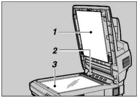
ADC107S
- Background Panel for Exposure Glass
2.ADF Exposure Glass 1
3.Exposure Glass
Cleaning Under the Background Panel
Note
☐The cleaning procedures below are not necessary for the simplex model.
1 Turn off the power of the scanner and unplug the power cord from the outlet.
2 Lift the Pressure Panel.
3 Take off the Background Panel.
ADC035S
Reference
⇒ p.54 "Changing the Color of the Background Panel for the Exposure Glass"
4 Turn down blue levers on both sides.
ADC036S
5 Wipe the ADF Exposure Glass 2 with the cleaning cloth or a dry and soft cloth.
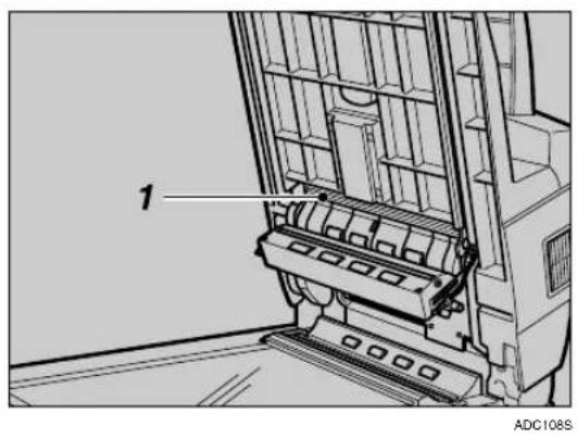
1.ADF Exposure Glass 2
6 Wipe the rollers with a tightly wrung cloth.
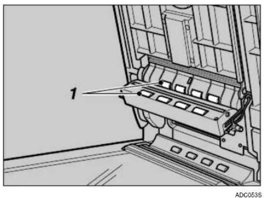
- Rollers
Reference
Regarding how to set back the store box for the ADF Background Panel, please refer to the step 5 of p.52 "Changing the Color of the Background Panel for the ADF"
Regarding how to set the Background Panel for the Exposure Glass, please refer to p.54 "Changing the Color of the Background Panel for the Exposure Glass".
Cleaning Inside the ADF Cover
1 Turn off the power of the scanner and unplug the power cord from the outlet.
2 Open the cover of the ADF.
3 Wipe the rollers with a tightly wrung cloth, by turning them with your fingers.
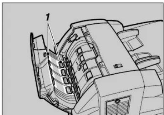
natural_image
Technical line drawing of a mechanical assembly with numbered component (no text or symbols)ADC110S
- Rollers
4 Wipe the rollers in the cove with a tightly wrung cloth, by turning them with your fingers.
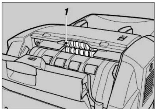
natural_image
Technical line drawing of a car engine compartment with internal components and a numbered component (no text or symbols)ADC111S
- Rollers
Note
□When you shut the ADF cover, please confirm the two magnets are fixed on the magnet catch and the cover is closed tightly.
Cleaning the Ventilation Panel
Please clean the filter and the ventilation panel in every six months. However, please clean it properly when it gets dirty.
1 Turn off the power of the scanner and unplug the power cord from the outlet.
2 Open the ventilation cover panel on the left side of the ADF, and clean the inside filter and the ventilation panel.
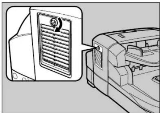
natural_image
Diagram showing a ventilation grille mounted on a door panel, with a close-up view of the grille (no text or symbols present)ADC056S
Moving and Transporting the Scanner
CAUTION:
• This scanner weighs approximately 72.8 lbs.
- Make sure to lift it carefully with two persons or more so as to minimize physical strain. Careless lifting, reckless handling or allowing it to drop down can cause injury.
- When transporting over long distances, please consult an authorized dealer.
- Safety laws and regulations (including those stipulating radio wave regulations and material regulations) differ in each country. Use of this product and its consumable supplies, etc. in foreign countries in violation of these regulations may be punishable by law.
- Information regarding measures for ensuring safe transport can be obtained from an authorized dealer. However, packaging and transport are to be performed by the customer.
Moving Over Short Distances
1 Turn off the power of the scanner and unplug the power cord from the outlet.
2 Disconnect all cables connected to the scanner.
3 Transport the scanner.
ADC057S
Important
☐Try to keep the scanner as level as possible during transport.
Transporting the Scanner
1 Turn on the Power Switch. Allow the scanner to remain on for at least 20 seconds, and then turn it off.
2 Set the Lock Lever on the left side of the scanner to the “Lock” position.
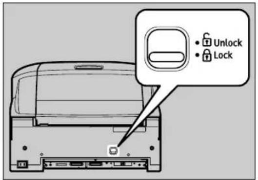
ADC068S
3 Fix it with the two lock screws kept on the back of the Pressure Panel.
① Lift the Pressure Panel, and carefully pull out the Background Panel that is fixed with the Velcro.
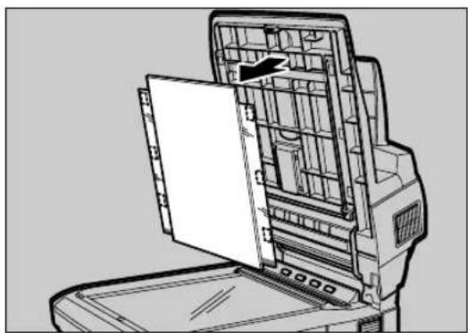
natural_image
Technical line drawing of a mechanical device with internal compartments and a door (no text or symbols)ADC0715
②Take out the lock screws kept on the back of the Pressure Panel.
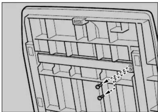
natural_image
Technical line drawing of a mechanical or electrical component with internal shelves and mounting brackets (no text or symbols)ADC085S
③Return the Background Panel to where it was.
Reference
Regarding how to set the Background Panel, please refer to the procedures 2 - 5 of p.54 "Changing the Color of the Background Panel for the Exposure Glass".
④Turn 90 degrees the caps that covered the holes for lock screws, and take out it.
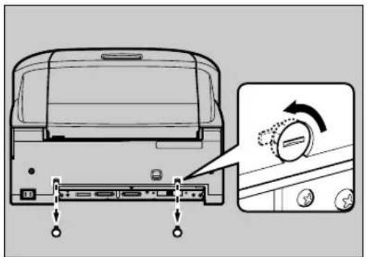
ADC0875
Note
☐The removed caps are to be kept in a bag and transported together with the machine, since they are used at the place where the machine is set up.
⑤ Fix tightly with the lock screws.
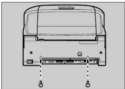
natural_image
Diagram of a rear view of a computer with two ports and connectors, no text or symbols presentADC083S
Note
☐Use a coin to tightly fix the lock screws.
4 Disconnect all cables connected to the scanner.
5 Place the scanner in original box and transport.
Important
☐This scanner is a precision device. Be careful so that it is not damaged during transport.
☐Use the cushioning materials provided with the scanner at the time of purchase.
Disposing of the Scanner
When you want to dispose of your scanner, contact your dealer or a service representative.
How Data Size Changes Depending on Scan Area and Resolution
Scan area and resolution determine the data size of a scanned data. The following general rules apply:
- High resolution (dpi) makes data size larger and scan area smaller.
- Large scan area makes data size larger and resolution (dpi) lower.
Note
☐In the following tables, each of the values displays the memory size to store as image data. Actual file sizes may vary depending on the file type setting (single page, PDF or multi-page TIFF).
☐A blank cell means that the combination of the relevant settings is not available.
□Even when a data size is shown in a cell, it may happen that you cannot perform a scanning operation with the relevant settings due to the limitation of the TWAIN-compliant application you use for scanning. For information about the maximum data size that the application can handle, see the manual that comes with the application.
When [Binary(Text)], [Binary(Photo)], [Binary(Auto Image)], or [Binary(Text/Photo)] is Selected
| Scan Area 100dpi | 200dpi | 300dpi 40 | 0dpi 500 | dpi 600dpi | 700dpi | 800dpi | |||
| A | 3 | 2 | 3 | 5 | 9 | 4 | 3 | 2 | |
| B | 4 | 1 | 7 | 6 | 7 | 0 | 5 | 1 | |
| A4 | 117 470 | 1,061 | 1,886 | 2,946 4,247 | - | - | |||
| B5 | 87 | 353 | 794 | 1,414 | 2,208 | 3,183 | - | - | |
| A5 | 58 | 234 | 528 | 939 | 1,469 | 2,116 | 2,876 | 3,759 | |
| B6 | 43 | 174 | 394 | 702 | 1,098 | 1,582 | 2,155 | 2,815 | |
| A6 | 29 | 117 | 264 | 468 | 734 | 1,058 | 1,437 | 1,880 | |
| 11'' × 17'' | 227 | 913 | 2,051 | 3,652 | - | - | - | - | |
| 8^1''/_2 × 14'' | 144 | 579 1,304 | 2,324 3,629 | - | - | - | |||
| 8^1/_2'' × 13'' | 134 | 538 1,211 | 2,158 3,370 | - | - | - | |||
| 8^1/_2'' × 11'' | 113 | 455 1,024 | 1,826 2,852 | - | - | - | |||
| 5^1/_2'' × 8^1/_2'' | 56 | 227 | 512 | 913 | 1,423 | 2,051 | 2,794 | 3,652 | |
Values: Data size in KB
When [Gray Scale] or [256 Colors] is Selected
| Scan Area 100dpi | 200dpi | 300dpi 40 | 0dpi 500 | dpi 600dpi | 700dpi | 800dpi | |||
| A | 3 | 1 | , | 8 | 8 | 8 | 7 | , | 5 |
| B | 4 | 1 | , | 4 | 1 | 6 | 5 | , | 6 |
| A4 | 944 | 3,776 | 8,496 | 15,105 | 23,601 | 33,986 - | - | ||
| B5 | 708 | 2,832 | 6,372 | 11,328 | 17,700 | 25,488 - | - | ||
| A5 | 470 | 1,881 | 4,234 | 7,527 | 11,761 | 16,936 | 23,052 | 30,108 | |
| B6 | 352 | 1,410 | 3,173 | 5,642 | 8,815 | 12,694 | 17,278 | 22,568 | |
| A6 | 235 | 940 | 2,117 | 3,763 | 5,880 | 8,468 | 11,526 | 15,054 | |
| 11'' × 17'' | 1,826 | 7,304 | 16,435 | 29,218 | - | - | - | - | |
| 8^1/_2'' × 14'' | 1,162 | 4,648 | 10,458 | 18,593 | 29,052 - | - | - | ||
| 8^1''/_2 × 13'' | 1,079 | 4,316 | 9,711 | 17,265 | 26,977 | - | - | - | |
| 8^1/_2'' × 11'' | 913 | 3,652 | 8,217 | 14,609 | 22,827 - | - | - | ||
| 5^1/_2'' × 8^1/_2'' | 456 | 1,826 | 4,108 | 7,304 | 11,413 | 16,435 | 22,370 | 29,218 | |
Values: Data size in KB
When [8 Colors] or [8 Colors(Photo)] is Selected
| Scan Area 100dpi | 200dpi | 300dpi 40 | 0dpi 500 | dpi 600dpi | 700dpi | 800dpi | |||
| A | 3 | 7 | 0 | 7 | 2 | , | 8 | 2 | |
| B | 4 | 5 | 2 | 9 | 2 | , | 1 | 1 | |
| A4 352 1,411 3,185 5,659 8,838 1 | 2,743 - | - | |||||||
| B5 | 263 | 1,061 | 2,383 | 4,244 | 6,625 | 9,550 | - | - | |
| A5 174 702 1,584 | 2,819 4,40 | 8 6,350 8 | 630 11,277 | ||||||
| B6 | 130 | 524 | 1,183 2,10 | 7 3,295 4 | 748 6,465 | 8,447 | |||
| A6 | 87 | 351 | 793 | 1,406 | 2,202 | 3,175 | 4,313 | 5,640 | |
| 11" × 17" | 682 | 2,739 | 6,155 | 10,957 | - | - | - | - | |
| 8^1/_2'' × 14'' | 434 | 1,739 3,91 | 2 6,972 1 | 0,889 - | - | - | |||
| 8^1/_2'' × 13'' | 403 | 1,614 3,63 | 3 6,474 1 | 0,111 - | - | - | |||
| 8^1/_2'' × 11'' | 341 | 1,366 3,07 | 4 5,478 8 | 556 - | - | - | |||
| 5^1/_2'' × 8^1/_2'' | 169 | 682 | 1,538 2,73 | 9 4,270 6 | 155 8,384 | 10,957 | |||
Values: Data size in KB
When [16770K colors] is Selected
Scan Area 100dpi 200dpi 300dpi 400dpi 500dpi 600dpi 700dpi 800dpi
A3 5,663 22,655 50,977 90,628 - - - -
B4 4,247 16,989 38,231 67,964 - - - -
A4 2,831 11,327 25,486 45,314 70,802 101,954 --
B5 2,123 8,495 19,113 33,982 53,100 76,460 --
A5 1,411 5,645 12,701 22,581 35,283 50,807 69,154 90,324
| B6 | 1,057 | 4,230 | 9,519 | 16,925 | 26,446 | 38,079 | 51,832 | 67,701 |
| A6 | 705 | 2,822 | 6,350 | 11,289 | 17,639 | 25,401 | 34,577 | 45,162 |
| 11'' × 17'' | 5,478 | 21,914 | 49,306 | 87,656 | - | - | - | - |
8^1/_2'' × 14'' 3,486 13,945 31,376 55,781 87,158 ---
8^1 / _2'' × 13'' 3,237 12,949 29,135 51,796 80,932 ---
8^1 / _2'' × 11'' 2,739 10,957 24,653 43,828 68,481 ---
5^1 / 2'' × 8^1 / 2'' 1,369 5,478 12,326 21,914 34,240 49,306 67,111 87,656
Values: Data size in KB
Options
In this section, we refer to the options for this machine.
Image Processing Unit Type B
Installation of this option enables the following visual image processing by use of the TWAIN driver.
◆Binary(Auto Image)
When you binary-scan an original mainly with text files, this machine automatically detects and scans an appropriate threshold value.
Binary(Text/Photo)
Set when you scan an original consisting of both texts and photos. It scans with binary, and automatically detects and scans the photos to represent a para-intermediate tone (gray) with a black and white net-dot pattern.
Select Range
Set when you Binary-scan an original consisting of both texts and photos. You can set the photo part alone as the para-intermediate (gray) tone. For an original mainly occupied by photos, to the contrary, you can detect and scan the original as a whole as the para-intermediate (gray) tone, setting the text part alone as non-intermediate (gray) tone. The maximum number of ranges to have partially different setting from the overall setting is 4.
IEEE1394 Interface Unit Type IS760
You can connect your PC to the IEEE1394 Interface board
Two IEEE1394 connectors are available, and you can connect a total of 3 PCs to this machine together with another SCSI connector equipped.
Limitation
☐The pre-installed USB 2.0 interface board is to be used exclusively.
Note
☐You cannot use simultaneously two or more PCs connected. Connection is automatically switched to either SCSI, IEEE1349-1 or IEEE1349-2.
Specifications
Type flatbed type color scanner with ADF
Scanning method Fixed document scanning and moving document scanning
The duplex model enables scanning of both sides of an original simultaneously.
Scanning area ^*1
ADF
- One side color
Main direction: 12 inch (297 mm) Max., 2.7 inch (69 mm) Min. Sub direction: 24.8 inch (630 mm) Max., 3.5 inch (90 mm) Min.
• One side monochrome
Main direction: 12 inch (297 mm) Max., 2.7 inch (69 mm) Min. Sub direction: 78.7 inch (2000 mm) Max., 3.5 inch (90 mm) Min.
- Both side color, Both side monochrome (The duplex model machine only) Main direction: 12 inch (297 mm) Max., 2.7 inch (69 mm) Min. Sub direction: 17 inch (432 mm) Max., 3.5 inch (90 mm) Min.
◆Exposure Glass
Main direction: 12 inch (297 mm) Max., 0.4 inch (10 mm) Min. Sub direction: 17 inch (432 mm) Max., 0.4 inch (10 mm) Min.
Optical resolution Main scanning: 400 dpi
Sub scanning: 400 dpi
Scanning grade Input: 10 bits per pixel for each color
Output: 1 bit per pixel for monochrome and 8 bits per pixel for each color
Scanning time of 1 line binary: 0.229 msec/line
color: 0.558 msec/line
ADF Scanning
time ^*2
Simplex binary scanning: 75 ppm ( 8^1/_2'' × 11'' / 200 dpi)
Duplex binary scanning: 122 ipm *3 (8 1/2" × 11" / 200 dpi Duplex model only)
Simplex full color scanning: 40 ppm ( 8^1/_2'' × 11'' / 200 dpi)
Duplex full color scanning: 62 ipm ^*3 8 ^1 / _2 "× 11" / 200 dpi Duplex model only )
Original 200 sheets ( 8^1/_2'' × 11'', 64 g/m^2 )
Stacks
Paper 40-157 g/m² (77–298 lbs)
Weights
Interface Standard SCSI-3
USB 2.0
Option IEEE1394 × 2 (Alternative with USB2.0)
Life ADF: 3,000,000 scans, Flatbed: 600,000 scans, or 5 years
Operating environment
Temperature: 50-90 °F (10-32 °C), humidity 15-80 %
Power 120 V, 60 Hz
| Power consumption During operation: 180 WDuring standby: 50 WDuring Low-Power mode: 8 W | |
| Warm-up time Max. 20 seconds | |
| Transition time to the Low-Power mode/Recovery time from the Low-Power mode | Transaction time: About 15 minutesRecovery: 3 seconds or shorter |
| Dimensions | 19.3 inch × 27.4 inch × 13 inch (490 mm × 695 mm × 332 mm) (W × D × H) |
| Weight Simplex Scanner: Approximately 68.3 lbs (31 kg)Duplex Scanner: Approximately 72.8 lbs (33 kg) | |
*1 The maximum scanning range varies by the level of resolution and grade.
*2 Actual length of time for the scanning varies by your PC performance and environments.
*3 ipm: images per minute
INDEX
A
ADF, 7
Jammed Originals, 64
Originals that cannot be set, 47
ADF Cover, 8
ADF Exposure Glass, 8
ADF Exposure Glass 1, 73
ADF Exposure Glass 2, 74
Auto Detection
Original Sizes, 46
Automatic Document Feeder, 7
B
Background Panel for Exposure Glass, 8, 73
Background Panel for the ADF
Changing the Color, 52
Background Panel for the Exposure Glass
Changing the Color, 54
C
Cleaning
ADF Exposure Glass 1, 73
ADF Exposure Glass 2, 74
Background Panel for Exposure Glass, 73
Exposure Glass, 73
Feed Roller, 72
Filter, 77
【Clear Modes】key, 7
Connecting
Computer, 21
IEEE1394, 29
IEEE1394 Board, 18
Image-Processing Unit, 16
Options, 16
Power Code, 31
SCSI, 21
USB, 28
D
Data Size, 82
DeskTopBinder Lite
Installation, 38
DIP Switches, 7,10
Disposing, 81
E
Error Indicators, 63
Error Message and Required Action, 67
Error on the Original Table, 66
Exposure Glass, 8,73
F
Feed Roller, 72
Filter, 77
G
Guide to This Scanner, 7
H
Hard Reset Switch, 7, 34
I
IEEE1394 Board, 18
IEEE1394 Interface Unit Type IS760, 85
Image-Processing Unit, 16
Image Processing Unit Type B, 85
Indicators, 7
In Normal State, 9
With Error, 63
Installing
DeskTopBinder Lite, 38
ISIS Driver, 40
QuickScan, 43
TWAIN Driver, 35
ISIS Driver
Installation, 40
J
Jam, 64
L
Lock Lever, 8
M
Moving 78
0
Operating Instructions, 5
Options, 85
Originals Size, 45
Original Stopper, 7
Originals Weight, 45
Original Table, 7
Output Table, 7
P
Placing Originals
In the ADF, 49
On the Exposure Glass, 48
Power Connector, 8
Power Switch, 7
Pressure Panel, 8
Q
Quick Installation Guide, 5
QuickScan
Installation, 43
R
Resolution and Data Size, 82
Rotary Switch, 7
s
Scan Area and Data Size, 82
SCSI ID
Setting Automatically, 23
Setting Manually, 22
SCSI Interface Connector, 8
SD Card Slot, 8
Setting Originals, 45
Sizes Automatically Detected, 46
Specifications, 86
【Start】key, 7
Surroundings for Setup, 11
T
Transporting, 78
Troubleshooting, 63
Turning the Power On/Off, 33
TWAIN Driver
Example of the Scanning, 58
Functions, 60
Installation, 35
Procedure Breakdown, 57
U
USB 2.0 Interface Connector, 8
MEMO
In accordance with IEC 60417, this machine uses the following symbols for the main power switch:
means POWER ON.
O means POWER OFF.
- Introduction
- Important
- Caution
- Power Source
- Trademarks
- TABLE OF CONTENTS
- Guide to Components
- Setting up the Scanner
- Installing Software
- Setting Originals
- Using the TWAIN Driver
- Appendix
- Safety Information
- Safety During Operation
- WARNING:
- CAUTION:
- Energy Star Program
- ◆Low-Power mode
- Note
- Specifications
- Manuals for This Scanner
- How to Read This Manual
- Symbols
- ⚠ WARNING:
- Preparation
- Limitation
- Reference
- Guide to This Scanner
- ADF (Automatic Document Feeder)
- Paper Thickness Changeover Lever
- Original Table
- Output Table
- Original Stopper
- 6.Rotary Switch
- 7.DIP Switches
- 8.Hard Reset Switch
- 9.Indicators
- 10.【Clear Modes】key
- 11.【[Start] key
- 12.Power Switch
- Pressure Panel
- Background Panel for Exposure Glass
- 3.ADF Exposure Glass
- 4.Exposure Glass
- 5.ADF Cover
- 6.Lock Screw
- 7.USB 2.0 Interface Connector
- 8.Lock Lever
- 9.SCSI Interface Connector
- 10.SD Card Slot
- 11.Power Connector
- Understanding Indicators
- DIP Switches
- Confirmations Before the Setup
- Location, Space and Environment
- Location
- Space
- Environment
- Disengaging the lock for transportation
- Installing Options
- Installing the Image-Processing Unit
- Installing the IEEE1394 Interface Board
- Connecting to the Computer
- Connecting with SCSI Interface
- About the SCSI Interface
- Setting the SCSI ID
- Setting the SCSI ID Automatically
- Connecting the SCSI Cable (When the Scanner is at the End of the Daisy Chain)
- Connecting the SCSI Cable (When the Scanner is not at the End of the Daisy Chain)
- Using the Scanner only with the SCSI Connection
- Connecting with USB Interface
- Connect the USB cable to the USB connector.
- Connect the other side of the cable to the USB connector on your computer.
- Connecting with IEEE1394 Interface
- Open the cover of the switch box on the lower left of the frontside of the scanner.
- Connecting to a Power Source
- Confirm that the power switch is set to Off.
- Confirm the lock screws on the back of this machine are removed and the holes left by the removed screws are covered with the caps.
- Turning the Power On/Off
- Turning the Power On when Connected with SCSI Interface
- Turning the Power On when Connected with USB/IEEE1394 Interface
- Turning the Power Off
- Using the Hard Reset Switch
- Installing TWAIN Driver
- System Requirements
- About TWAIN driver help
- Changing the connecting interface
- Installing DeskTopBinder Lite
- Installing ISIS Driver
- Installing QuickScan
- Sizes and Weights of Recommended Originals
- Original Sizes Available for Auto Detection
- When the Background Panel is Black
- When the Background Panel is White
- Originals that Require Special Care
- ◆Originals that are difficult to detect the size automatically
- ◆Originals that cannot be set in the ADF
- Placing Originals
- Placing the Original on the Exposure Glass
- Placing the Originals in the ADF
- ◆Precautions when placing an original in the ADF
- Adjust the stopper of the Output Table to the size of your originals.
- stopper
- 1.Side guides
- Changing the Color of the Background Panel
- Changing the Color of the Background Panel for the ADF
- Changing the Color of the Background Panel for the Exposure Glass
- 1.Home position
- Procedure Breakdown
- Scanning Originals
- Click [Scan...]
- Save the scanned image in DeskTopBinder Lite.
- Close DeskTopBinder Lite.
- What You Can Do with the TWAIN Driver
- Troubleshooting
- Error Indicators
- When the Original is Jammed or Double Fed in the ADF
- When the Originals are Not Fed Correctly
- When Scanning is Not Performed as Expected
- When an Error Message Appears
- Cleaning
- R WARNING:
- R CAUTION:
- Cleaning the Original Table Cove
- Feed Roller
- Cleaning Under the Pressure Panel
- Cleaning Under the Background Panel
- Cleaning Inside the ADF Cover
- Cleaning the Ventilation Panel
- Moving and Transporting the Scanner
- Moving Over Short Distances
- Transporting the Scanner
- Disposing of the Scanner
- How Data Size Changes Depending on Scan Area and Resolution
- When [16770K colors] is Selected
- Options
- Image Processing Unit Type B
- ◆Binary(Auto Image)
- Binary(Text/Photo)
- Select Range
- IEEE1394 Interface Unit Type IS760
- ADF
- ◆Exposure Glass
- INDEX
- A
- B
- C
- D
- E
- F
- G
- H
- I
- J
- L
- M
- 0
- P
- Q
- R
- s
- T
- U
Brand : RICOH
Model : IS760D
Category : Scanner