SSVC6D - Switch OSD Audio - Free user manual and instructions
Find the device manual for free SSVC6D OSD Audio in PDF.


| Product Type | 6-Zone Speaker Selector with Dual Source |
| Number of Zones | 6 independent stereo zones |
| Source Selection | Dual source A/B with master switch on front panel |
| Volume Control | 6 individual rotary style internal volume controls, 12-step 54dB attenuation |
| Impedance Matching | Automatic adjustable impedance matching protection circuitry (1X, 2X, 4X, 8X jumpers) |
| Front Panel Controls | Slotted on/off buttons for each zone, master source switch (A/B) |
| Connectors | Heavy-duty removable input/output connectors, accepts up to 14 AWG speaker cable |
| Ground Isolation | Isolated left/right circuit grounds for floating or bridged amplifiers |
| Faceplate Material | Brushed aluminum |
| Power Requirement | Passive device, no power supply needed |
| Speaker Compatibility | 4, 6, 8, and 16 ohm speakers |
| Recommended Wire | 16 AWG stranded; 14 AWG for runs over 50 ft |
| Safety Precautions | Do not expose to rain or moisture; use damp cloth for cleaning; avoid AC power wiring proximity |
| Installation | Turn off amplifier before wiring; strip 3/8" insulation; use removable connectors |
| Warranty | Limited Warranty (see manual for details) |
Frequently Asked Questions - SSVC6D OSD Audio
User questions about SSVC6D OSD Audio
0 question about this device. Answer the ones you know or ask your own.
Ask a new question about this device
Download the instructions for your Switch in PDF format for free! Find your manual SSVC6D - OSD Audio and take your electronic device back in hand. On this page are published all the documents necessary for the use of your device. SSVC6D by OSD Audio.
USER MANUAL SSVC6D OSD Audio
What's Included.... 2
Introduction.... 3
Front Panel.... 3
Rear Panel....3
Typical Hook up.... 4
Installation Tips....4
Installation....4
Operation....5
Trouble Shooting....5
Technical Specifications....5
Limited Warranty.... 5
IMPORTANT SAFTY PRECAUTIONS
When using this product, basic safety precautions should always be followed to reduce the risk of fire and electric shock, including the following:
- Read and understand all instructions.
- Follow all warnings and instructions marked on this product.
- Do not use liquid or aerosol cleaners. Use a damp cloth for cleaning.
- To prevent fire or shock hazard, do not expose this product to rain or moisture. Do not use near a bath tub, wash bowl, sink, or laundry tub; do not use in a wet basement or in a swimming pool.
- To avoid electrical shock, do not open the case of this product.
- The unit should be situated away from heat sources such as radiators, stoves, etc.
What's Included
1 - Speaker Selector
1 - This instruction manual
INTRODUCTION
The speaker selector series has been designed to let you add speakers around your home or office while maintaining a central control. Turn them on and off and adjust the volume without requiring additional amplifiers.
SSVC6D
6-Zone Speaker Selector with Dual Source (A or B) Operation, Internal Volume Controls and Adjustable Impedance Matching
- Connect and control up to 6 independent zones with Dual Source (A or B Master Switch)
• Automatic, adjustable (internal) impedance matching protection circuitry - 6 individual Rotary Style Internal volume controls with 12-step 54dB attenuation
- Easily labeled, front-mounted slotted push on/off button control
- Heavy-duty, removable input/output connectors accept up to 14ga speaker cable
- Isolated left/right circuit grounds for amplifiers with floating grounds or bridged configurations
- Advanced design for easy installation and hassle-free operation
- Brushed aluminum front faceplate
FRONT PANEL
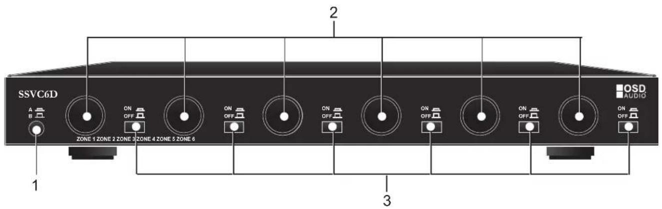
CONTROLS
- Master Source Switch (Select A or B)
- Rotary Style Volume Control Knob 6 total one for each Zone Six Individual Zone
- Six Individual Zone On/Off, Slotted buttons for easy labeling
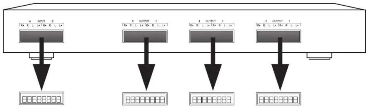
REAR PANEL:
- One Source A and B Input, Removable Connector
- Three Output Removable Connectors, Zones 1 & 2, Zones 3 & 4 and Zones 5 & 6
flowchart
graph TD
    A["Input Line A"] --> D1["Display Unit 10"]
    B["Input Line B"] --> D2["Display Unit 10"]
    C["Output Line 6"] --> D3["Display Unit 10"]
    E["Output Line 4"] --> D4["Display Unit 10"]
    F["Output Line 2"] --> D5["Display Unit 10"]
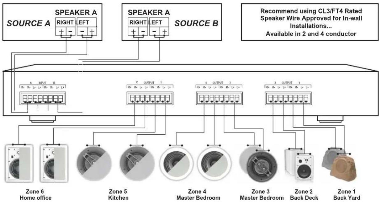
TYPICAL HOOKUP:
- Dual Source; choice of A or B Input, Master A or B Switch on front panel
- Three Dual Zone Connectors, Stereo Right and Left Positive and Negative Connections
flowchart
graph TD
    A["SOURCE A"] --> B["Speaker A"]
    B --> C["RIGHT LEFT"]
    B --> D["RIGHT LEFT"]
    E["SOURCE B"] --> F["Speaker A"]
    F --> G["RIGHT LEFT"]
    F --> H["RIGHT LEFT"]
    I["Zone 6 Home office"] --> J["Speaker A"]
    K["Speaker A"] --> L["OUTPUT 5"]
    M["Speaker A"] --> N["OUTPUT 3"]
    O["Speaker A"] --> P["OUTPUT 1"]
    Q["Speaker A"] --> R["OUTPUT 1"]
    S["Speaker A"] --> T["OUTPUT 1"]
    U["Speaker A"] --> V["OUTPUT 1"]
    W["Speaker A"] --> X["OUTPUT 1"]
    Y["Speaker A"] --> Z["OUTPUT 1"]
    AA["Speaker A"] --> AB["OUTPUT 1"]
    AC["Speaker A"] --> AD["OUTPUT 1"]
    AE["Speaker A"] --> AF["OUTPUT 1"]
    AG["Speaker A"] --> AH["OUTPUT 1"]
    AI["Speaker A"] --> AJ["OUTPUT 1"]
    AK["Speaker A"] --> AL["OUTPUT 1"]
    AM["Speaker A"] --> AN["OUTPUT 1"]
    AO["Speaker A"] --> AP["OUTPUT 1"]
    AQ["Speaker A"] --> AR["OUTPUT 1"]
    AS["Speaker A"] --> AT["OUTPUT 1"]
    AU["Speaker A"] --> AV["OUTPUT 1"]
    AW["Speaker A"] --> AX["OUTPUT 1"]
    AY["Speaker A"] --> AZ["OUTPUT 1"]
    BA["Speaker A"] --> BB["OUTPUT 1"]
    BC["Speaker A"] --> BD["OUTPUT 1"]
    BE["Speaker A"] --> BF["OUTPUT 1"]
    BG["Speaker A"] --> BH["OUTPUT 1"]
    BI["Speaker A"] --> BJ["OUTPUT 1"]
    BK["Speaker A"] --> BL["OUTPUT 1"]
    BM["Speaker A"] --> BN["OUTPUT 1"]
    BO["Speaker A"] --> BP["OUTPUT 1"]
    BQ["Speaker A"] --> BR["OUTPUT 1"]
    BS["Speaker A"] --> BT["OUTPUT 1"]
    BU["Speaker A"] --> BV["OUTPUT 1"]
    BW["Speaker A"] --> BX["OUTPUT 1"]
    BY["Speaker A"] --> BZ["OUTPUT 1"]
    CA["Speaker A"] --> CB["OUTPUT 1"]
    CC["Speaker A"] --> CD["OUTPUT 1"]
    CE["Speaker A"] --> CF["OUTPUT 1"]
    CG["Speaker A"] --> CH["OUTPUT 1"]
    CI["Speaker A"] --> CJ["OUTPUT 1"]
    CK["Speaker A"] --> CL["OUTPUT 1"]
    CM["Speaker A"] --> CN["OUTPUT 1"]
    CO["Speaker A"] --> CP["OUTPUT 1"]
    CS["Speaker A"] --> CK
    CT["Speaker A"] --> CU["OUTPUT 1"]
    CV["Speaker A"] --> CW["OUTPUT 1"]
    CX["Speaker A"] --> CY["OUTPUT 1"]
    CZ["Speaker A"] --> DA["OUTPUT 1"]
Note: Six independent Stereo zones with on/off button on front panel. As in the example, you can connect a number of different types of speakers including Rocks, Patio, In-Ceiling and In-Wall Speakers. Zone 3 features a single stereo Dual Voice Coil speaker with both a right and left stereo connection.
INSTALLATION TIPS
- OSD Audio recommends using 16 AWG gauge stranded wire. For runs longer than 50^ , 14 gauge is recommended.
- You can mix 4, 6, 8 and 16 ohm speakers.
- Since speakers have different efficiencies, more efficient speakers will sound louder than less efficient speakers. Select speakers with the same efficiencies (I.e., sensitivity: a typical measurement is 90 dB/watt)
- Wire according to state and local laws. Most states or counties require in-wall speaker wire with a specific "CL" fire rating. CL2 is for Residential only; CL3 is approved for both Residential and Commercial applications. This cable is available from OSD Audio or consult your dealer.
- Keep the speaker wiring from running close to AC power wiring for safety and to avoid any noise pick up.
INSTALLATION
Make sure your receiver or power amplifier is turned off before doing any wiring.
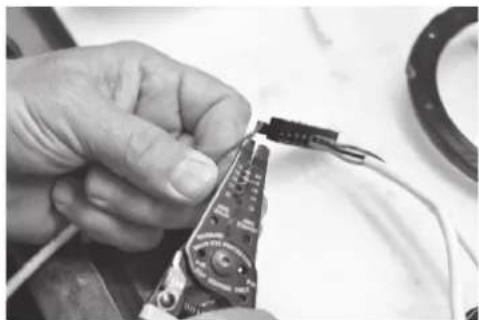
- When connecting wire, use a wire stripper and strip 3/8" of insulation from the end of the wire. To avoid short circuits and possible amplifier damage, do not strip too much insulation from the wire.
- Tightly twist the end of the wire so that there are no frayed wires.
- For wiring convenience, unplug connectors from the connector block. Verify that there are no wire frays. -Insert wire and tighten the terminal screw using a small screwdriver. Connect the wires from the speaker output from your receiver or amplifier to the SSVC6D terminals marked AMPLIFIER. Pay attention and connect the "+" output from the right front output on the amplifier to the right "+" input on the SSVC6D and connect the "-" output from your amplifier to the "-" input on the SSVC6D. Likewise, connect the left channel wires to the left input of the SSVC6D.
- Next, connect the wires from each of the speakers to the corresponding connection on the SSVC6D. If you are using a second amplifier, connect it to the AMP B terminal. Plug connectors back into the unit. Warning: Be sure connectors are plugged in correctly – do not shift over one pin.
natural_image
Close-up of a hand holding a small black wire connector to a circuit board (no visible text or symbols)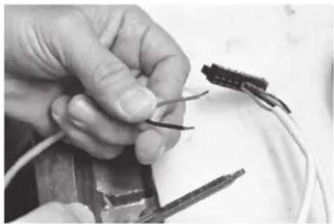
natural_image
Close-up of hands holding wires and a small electronic component (no visible text or symbols)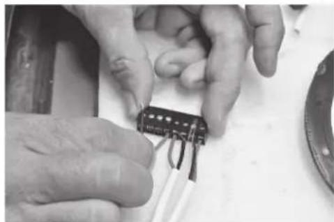
natural_image
Close-up of hands assembling an integrated circuit chip (no visible text or symbols)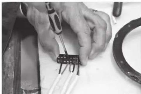
natural_image
Close-up of hands using a screwdriver to adjust or install a component with wires (no visible text or symbols)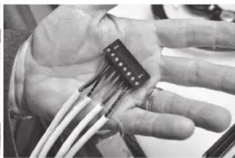
natural_image
Close-up of a hand holding a small electronic component with wires (no visible text or symbols)OPERATION
For initial connection, OSD Audio recommends selecting one speaker pair located closest to the room where you are operating the SSVC6D. Select this speaker pair and turn on your receiver/amplifier. Make sure sound is coming from both speakers. Before you turn on additional speakers, read the information below.
This Volume Control is a passive device (no power supply) that takes a signal from the source and allows you to attenuate or turn the sound down. It does not add or increase the gain. Its main function is to provide impedance matching of your speakers to the amplifier or receiver to which the SSVC6D is connected. This is especially important when playing more than two pair of speakers at once. Each internal volume control has impedance jumpers that allow users to select 1X, 2X, 4X or 8X. These settings correspond to the number of speaker pairs you will be adding to each zone and should be adjusted accordingly. The default is 4X for each. Changing the settings involves removing the cover of the Speaker Selector. If you have a question regarding changing these jumper settings you should first call our tech support at OSD Audio to walk you through the procedure.
Level Controls: Turning the level control fully counterclockwise will reduce the level of sound to fully muted. Turning the level control clockwise will increase the volume in approximately 3 dB to 6 dB increments (depending on which of the 12 steps for a total of 54dB). Note: Even though there is no sound coming out of the speakers when turned fully counterclockwise, the Volume Control is still engaged and drawing signal to its transformers. OSD Audio recommends using the on/off switch for the respective zone to fully turn the Volume Control off
Note: Refer to your amplifier or receiver's user manual or on the rear panel of the unit to determine the minimal speaker impedance that your amplifier can handle.

Brand : OSD Audio
Model : SSVC6D
Category : Switch