
AV-3104 - Controller AViPAS - Free user manual and instructions
Find the device manual for free AV-3104 AViPAS in PDF.


| Product Type | PTZ Camera Control Keyboard |
| Brand | AViPAS |
| Model | AV-3104 |
| Dimensions | 13 x 7 x 4 in (320 x 179.3 x 106.4 mm) |
| Power Supply | DC 12V ±10%, 6W max |
| Communication Interfaces | RS485 (half-duplex), RS422 (full duplex), RS232 |
| Supported Protocols | PELCO-D, PELCO-P, VISCA |
| Max Cameras Controlled | 255 |
| Joystick | 3-axis (pan/tilt/zoom) with speed control |
| Display | Backlit LCD (English & Chinese) |
| Baud Rates | 2400, 4800, 9600, 19200 bps |
| Max Transmission Distance | Up to 1200m (with 0.5mm twisted pair) |
| Over-current Protection | On RS422 interface |
| Button Sound | Selectable on/off |
| Keyboard Lock | Available |
| Operating Temperature | -10°C to 50°C |
| Humidity | ≤90% RH (non-condensing) |
| Housing Material | Metal |
| Included Accessories | DC 12V power adapter, RS232 cable, 5-pin plug, user manual, warranty card |
| Warranty | 1 year (defects in materials and workmanship) |
| Maintenance | Clean with dry cloth; avoid moisture, oil, and extreme temperatures |
Frequently Asked Questions - AV-3104 AViPAS
User questions about AV-3104 AViPAS
0 question about this device. Answer the ones you know or ask your own.
Ask a new question about this device
Download the instructions for your Controller in PDF format for free! Find your manual AV-3104 - AViPAS and take your electronic device back in hand. On this page are published all the documents necessary for the use of your device. AV-3104 by AViPAS.
USER MANUAL AV-3104 AViPAS
3D Joystick Keyboard Controller
![AVIPAS [AVIPAS]](/content/2026/05/950400/images/6c5af67842fae598e66c3d1dc1e1e56c0126cd36e3ee610b189030cfd8f101ad.jpg)
User Manual
V1.0
(English)
Please read this user manual thoroughly before using.
Contents
1.Brief Introduction....2
1.1 Notice....2
1.2 Functions and Features....2
1.3 Items Included....2
2.Interface Illustrations....3
2.1 Rear panel....3
2.2 Wiring diagram....3
2.3 Connection between keyboard and camera....4
2.4 Connection between cameras....4
3. Technical Specifications....5
3.1 General specifications....5
3.2 Input/Output interface....5
3.3 IPC features....5
4.Controller Operations....6
4.1 Keyboard....6
4.2 LCD screen display....7
4.3 Joystick control....7
5. Keyboard Setups....7
5.1 PTZ setup....7
5.2 System setup....8
5.2.1 Password setting....8
5.2.2 Restore factory settings....9
5.3 Keyboard menu....10
5.4 Keyboard parameters....10
6. Appendix....11
6.1 Transmission distance....11
6.2 Connection method and terminating resistor....11
6.3 Applications....11
6.4 Trouble shooting....12
7. Maintenance Service Terms....13
7.1 Range of warranty....13
7.2 Warranty conditions....13
7.3 Shipping....14
1. Brief Introduction
1.1 Notice
- Please read this manual thoroughly before use, and keep it handy for future reference.
- Do not use or store AV-3104 in the environment where the product is exposed to rainwater, moisture vapor, salty water, oil, etc.
- Do not place the controller close to any exothermic object for a long time.
1.2 Functions and features
- AV-3104 is equipped with RS485/RS422/RS232 serial control ports. It can control up to 255 cameras max.
• Support PELCO-D, PELCO-P and VISCA protocols.
● Metal housing, with computer keyboard buttons. - Adopt 3D joystick for camera pan/ tilt/ zoom and speed control.
- Control camera rotation, zoom, aperture, focus and other camera parameter settings.
- English & Chinese LCD display; real-time working status of the connected decoder and matrix.
- Selectable button sound on/off.
- Advanced control code learning function that supports user-defined control code commands.
- Any device connected via RS485 can be set with identical protocol and baud rate separately.
- Over-current protection functions for RS422 interface, in case the controller needs to recover from short circuit.
- Max communication distance is up to 349ft (1200m, w/ 0.5mm twisted pair cable).
1.3 Items included
Please check the items in the package once get the keyboard. Check whether all parts are included and are in good condition.
3-axis control keyboard....1 pc
5pin plug....1 pc
DC-12V power adapter....1 pc
RS232 cable....1 pc
(9-Pin DB-9 Female to 8-Pin Mini-DIN Male)
User manual....1 pc
Warranty card....1 pc
2. Interface Illustrations
2.1 Rear panel

| Port | Physical interface | Description | |
| 1 | RS-422 | Control output(Ta,Tb,Ra,Rb) | Connect with RS-485: Ta -> RS485+ ; Tb -> RS485- Connect with RS422: Ta -> RXD IN- ; Tb -> RXD IN+ Ra -> TXD IN- ; Rb -> TXD IN+ |
| 2 | Ground | Ground (G) | Signal control line to ground |
| 3 | PW | Power indicator light | The light is always red when keyboard is working |
| 4 | TXD | Sending data indicator light | The light will flicker in green when the unit is sending data |
| 5 | RXD | Receiving data indicator light | The light will flicker in green when the unit is receiving data |
| 6 | DC-12V | Power jack | DC12V power input |
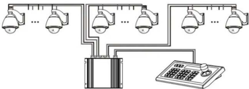
2.2 Wiring diagram
Connection with surveillance dome cameras:
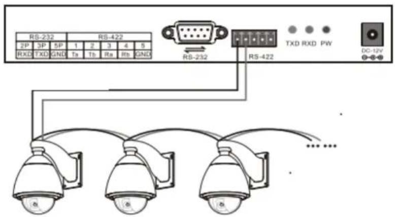
Connection with PTZ cameras:
- Connect the RS485+ on the cameras with Ta on the controller; RS485- with Tb.
- Deputy control devices: either RS485 output from DVR or keyboard is available.

2.3 Connection between keyboard and camera
RS422:
RS232:
KBD CAMERA
Ra <……> TXD IN-
Rb <……> TXD IN+
Ta <……> RXD IN-
Tb <……> RXD IN+
KBD CAMERA
RXD <……> TXD
TXD <……> RXD
GND <……> RXD
2.4 Connection between cameras
RS422:

flowchart
graph TD
    A["VISCA Equipment"] --> B["IN"]
    A --> C["OUT"]
    B --> D["IN"]
    B --> E["OUT"]
    C --> F["IN"]
    C --> G["OUT"]
    D --> H["IN"]
    D --> I["OUT"]
    E --> J["IN"]
    E --> K["OUT"]

RS232:

3. Technical Specifications
3.1 General specifications
| Communication mode | RS485 half-duplex, RS422 full duplex, RS232 serial port |
| Baud Rate | 2400bps, 4800bps, 9600bps, 19200bps |
| Interface | 5PIN Crimping terminal, RS232 Port |
| Joystick | 3D control: up/ down/ left/ right/ rotate |
| Display | Backlight LCD screen |
| Input voltage | DC12V ±10% |
| Power consumption | 6W max |
| Temperature | -10°C~50°C |
| Humidity | ≤90%RH (No frosting) |
| Dimension | 13*7*4 inch (320*179.3*106.4mm) |
3.2 Input/ Output interface
- Directly control: PELCO-P/PELCO-D/VISCA protocol
• Control interfaces: RS422, RS232, RS485
3.3 IPC features
• Communication frequency: 2400/4800/9600/19200 bps
4. Controller Operations
4.1 Keyboard


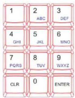
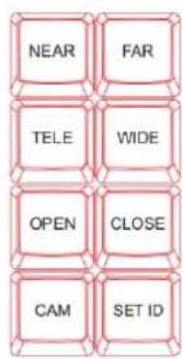
【ESC】 Exit or back to the previous menu.
【SETUP】 Parameter setting: press and hold the button for 3sec to enter the KBD parameter setting page.
【AF/MF】Auto focus/ Manual focus (when choose Manual focus, focus adjustment is done by 【FOCUS+】/【FOCUS-】.
【SET PRESET】Preset setting: to set a preset position, use key combination 【SET PRESET】+ number keys【0\~255】+【ENTER】.
【CALL PRESET】Call preset: to call a preset position, use key combination【CALL PRESET】+ number keys【0\~255】+【ENTER】.
【AE/AAE】Auto aperture / Aperture priority: when choose Aperture priority, aperture adjustment is done by 【OPEN】/【CLOSE】.
【BLC ON/OFF】 Back light compensation on/off.
【MENU ON/OFF】 keyboard controller menu on/off.
【NEAR】 Focus in: manually focus in to make far distance objects clearer.
【FAR】 Focus out: manually focus out to make near distance objects clearer.
【TELE】 Narrow-angle button/ Zoom-in: reduce the field of view, zoom in to the target object.
【WIDE】 Wide-angle button/ Zoom out: expand the field of view, zoom out from the target object.
【OPEN】 Aperture +: Increase aperture. When the aperture is at its maximum, the image will display in full white. When the LCD shows the camera menu, press 【OPEN】 will enter the selected submenu.
【CLOSE】Aperture -: Reduce aperture. When the aperture is at its minimum, the image will display in full black. When the LCD shows the camera menu, press 【CLOSE】 will go back to the previous menu.
【CAM】 Select the address of a target device (decoder or camera). Use with key combination number keys 【0\~255】 + 【ENTER】.
【SET ID】 Set ID: press and hold the button for 3sec to set the cascading camera protocol address.
4.2 LCD screen display
All operations will be displayed on the LCD screen. If there is no operation or movement for 30 sec, the controller will enter the power saving mode (with the lowest backlight), with the current status displayed.
4.3 Joystick control
| Operation | Output Control | Operation | Output Control | Operation | Output Control |
 | UP |  | Down |  | Left |
| Operation | Output Control | Operation | Output Control | Operation | Output Control |
 | Right |  | Zoom In |  | Zoom Out |
5. Keyboard Setups
5.1 PTZ setup
An example is used for instructions below:
- Camera Address (Camera ID): 28
- Protocol used: Pelco-P
- Baud rate: 9600 bps
Press and hold【SETUP】button for 3 seconds (under normal working mode), then follow the steps below:

flowchart
graph TD
    A["CAM: 001<br>PASSWORD: ----"] --> B["Enter password (default is 8888)"]
    B --> C["PTZ SETUP<br>SYS SETUP"]
    C --> D["Press【Enter】"]
    E["CAM: 001<br>P: VISCA BR:096"] --> F["Press【2】【8】"]
    F --> G["CAM: 028<br>P: VISCA BR:096"]
    G --> H["Press【Enter】"]
    I["CAM: 028<br>P: VISCA BR:096"] --> J["Move joystick downward to choose the right protocol: Pelco-P"]
    J --> K["CAM: 028<br>P: PELCOP BR:096"]
    K --> L["Move joystick rightward to choose the right baudrate: 9600"]
Press【ENTER】to confirm the selected baud rate. There will be a 1-sec beep sound once the setup is complete.
Press【ESC】3 times to exit the setup mode and return to normal working mode.
Note: if all the devices/ cameras are to be set to the same protocol and baud rate, please follow the steps as follows:
CAM: 0-255 P: VISCA BR:096 Enter the setup page and choose the corresponding protocol and baud rate.
Press【ENTER】to confirm. All the devices with an address of 0-255 will be set to the same protocol and baud rate.
5.2 System setup
System setup includes:
- Change password
- Restore factory setting
- Indicate sound switch setting
- Keyboard ID
- Keyboard lock switch setting
5.2.1 Password setting
Press and hold【SETUP】for 3 seconds (under normal working mode), then follow the steps below:
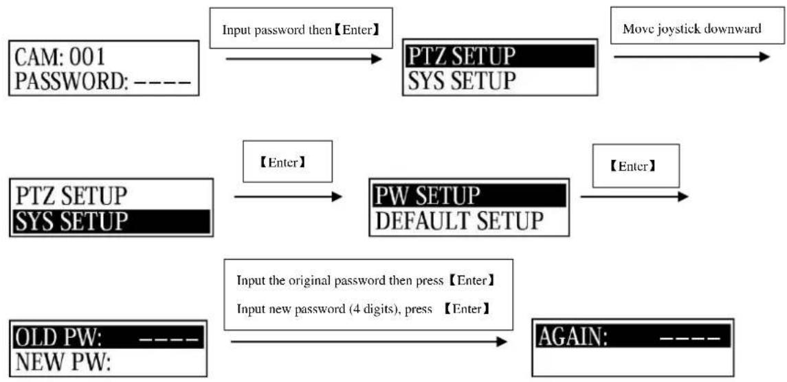
flowchart
graph TD
    A["CAM: 001 PASSWORD: ----"] --> B["Input password then【Enter】"]
    B --> C["PTZ SETUP SYS SETUP"]
    C --> D["Move joystick downward"]
    E["PTZ SETUP SYS SETUP"] --> F["【Enter】"]
    F --> G["PW SETUP DEFAULT SETUP"]
    G --> H["【Enter】"]
    I["OLD PW: ---- NEW PW:"] --> J["Input the original password then press【Enter】<br>Input new password (4 digits), press【Enter】"]
    J --> K["AGAIN: ----"]
Input the new password again then press【ENTER】. There will be a 1-sec beep sound once the setup is complete. Press【ESC】twice (2) to exit password setup page and return to the normal working mode.
5.2.2 Restore factory settings
Press and hold【SETUP】for 3 seconds (under normal working mode), then follow the steps below:

flowchart
graph TD
    A["CAM: 001 PASSWORD: ----"] -->|Enter password| B["PTZ SETUP SYS SETUP"]
    B -->|Move joystick downward| C["End"]
    D["PTZ SETUP SYS SETUP"] -->|【Enter】| E["PW SETUP DEFAULT SETUP"]
    E -->|Move joystick downward| F["End"]
    G["PW SETUP DEFAULT SETUP"] -->|【Enter】| H["PW SETUP DEFAULT SETUP ?"]
Press 【ENTER】 to confirm. There will be a 1-sec beep sound once the setup is complete. Press【ESC】twice (2) to exit password setup page and return to the normal working mode.
5.3 Keyboard menu
| > PTZ Setup | Camera address: 0-255 (to be set) | Protocol | PELCO-D, PELCO-P, VISACA |
| Baud Rate | 2400/ 4800/ 9600/ 19200 | ||
| Camera address: 0-255 (uniform settings for all devices) | Same as above | ||
| > SYSTEM Setup | > SET PASSWORD | OLD PW: old password | 4 digits |
| NEW PW: new password | 4 digits | ||
| AGAIN PW: confirm change | 4 digits | ||
| > LOAD DEFAU (restore factory setting) | Confirm? | Press 【ENTER】 to confirmPress【ESC】 to exit | |
| > SYSTEM Setup | > SOUND SETUP (button sound switch setting) | ON | Move joystick right/left to selectPress【ENTER】 to confirm |
| OFF | |||
| > HOST ID SET | Keyboard address | Number【0】 - 【15】 | |
| > LEARN SETUP (keyboard lock setting) | ON | Move joystick right/left to selectPress【ENTER】 to confirm | |
| OFF | |||
5.4 Keyboard parameters
| Protocol: XBaud rate: X | Current control protocol and baud rate | ||
| Camera query | Camera protocol: 001 | Protocol | Corresponding protocol |
| Baud rate | Corresponding baud rate | ||
| System query | Model number: XXXXXXXX | 10 digits max | |
| Serial number: XXXXXXXX | 8-digit serial number on camera | ||
| Device number: XX | 2-digit keyboard ID number | ||
| Keyboard lock: ON/OFF | Display the current keyboard lock setting | ||
| Sound: ON/OFF | Display the current button sound prompt setting | ||
6. Appendix
6.1 Transmission distance:
When a 0.56mm (24AWG) twisted pair cable is used as the communication cable, the theoretical value of the maximum transmission distance varies with different baud rate settings:
2400bps: 5900ft (1800m)
19200bps: 1960ft (600m)
When using a thinner communication cable, or when the product is used in an environment with strong electromagnetic interference, or when too many devices are connected to the same controller, the maximum transmission distance will be shortened accordingly.
6.2 Connection method and terminating resistor
RS485 industrial bus standard requires daisy chain connections between devices. The two ends must be connected with a 120Ω termination resistor, and the balance distance must be within22ft (7m).

6.3 Applications
A star link is in most real cases used when there is a switcher/router, requiring a terminating resistor to be used on the two devices on both ends. However, it does not meet the RS485 industry standards. When the distance between each device are too long, signal reflection and anti-interference ability is like to reduce, and will decrease the reliability of the control signal. It means the camera will not be responsive as expected. In this case, RS485 is recommended, so that you may convert the star link mode to RS485 industry standard. It will help avoid connection issues and improve the communication reliability.
flowchart
graph TD
    A["Camera 1"] --> B["Central Device"]
    C["Camera 2"] --> B
    D["Camera 3"] --> B
    E["Camera 4"] --> B
    F["Camera 5"] --> B
    G["Camera 6"] --> B
    H["Camera 7"] --> B
    I["Camera 8"] --> B
    J["Camera 9"] --> B
    K["Camera 10"] --> B
    L["Camera 11"] --> B
    M["Camera 12"] --> B
    N["Camera 13"] --> B
    O["Camera 14"] --> B
    P["Camera 15"] --> B
    Q["Camera 16"] --> B
    R["Camera 17"] --> B
    S["Camera 18"] --> B
    T["Camera 19"] --> B
    U["Camera 20"] --> B
    V["Camera 21"] --> B
    W["Camera 22"] --> B
    X["Camera 23"] --> B
    Y["Camera 24"] --> B
    Z["Camera 25"] --> B
    AA["Camera 26"] --> B
    AB["Camera 27"] --> B
    AC["Camera 28"] --> B
    AD["Camera 29"] --> B
    AE["Camera 30"] --> B
    AF["Camera 31"] --> B
    AG["Camera 32"] --> B
    AH["Camera 33"] --> B
    AI["Camera 34"] --> B
    AJ["Camera 35"] --> B
    AK["Camera 36"] --> B
    AL["Camera 37"] --> B
    AM["Camera 38"] --> B
    AN["Camera 39"] --> B
    AO["Camera 40"] --> B
    AP["Camera 41"] --> B
    AQ["Camera 42"] --> B
    AR["Camera 43"] --> B
    AS["Camera 44"] --> B
    AT["Camera 45"] --> B
    AU["Camera 46"] --> B
    AV["Camera 47"] --> B
    AW["Camera 48"] --> B
    AX["Camera 49"] --> B
    AY["Camera 50"] --> B
6.4 Trouble shooting
| Issue | Analysis | Solution |
| PTZ cameras not responsive | Check RS485 cable | Step 1: whether the RS485 A and B are reversedStep 2: whether the RS485 line is short-circuited |
| Check the correspondence of camera protocol and baud rate settings and those of the controller | Step 1: change the protocol and baud rateStep 2: restore the KBD default settings and change the camera settings accordingly | |
| Check whether the PTZ indicator light flickers when move the controller | PTZ indicator light flickers: check other possibilities;PTZ indicator light does not flicker: check if the RS485 connection is secure. If the connection is normal, please contact AViPAS for repairing. | |
| Part of the connected cameras not responsive | Check cable connections | Check and secure all connecting cables |
| Check protocol & baud rate settings | Check whether the current protocol and baud rate of each camera are correspondent. | |
| Check star wiring | Step 1: at the farthest end of RS485, connect a 120Ω resistorStep 2: use a RS485 splitter to the star connection | |
| Cameras move together | Check camera address (camera ID) setting | Check if the address numbers of the cameras (those moving together) are the same. Set identical address to each cameraNote: you need to reboot the camera after changing settings |
| Forgot password | Press and hold 【SETUP】to enter the system settings menu. Reset the password. | |
7. Maintenance Service Terms
7.1 Range of warranty
- AViPAS warrants its new product against defects in materials and workmanship for a period of ONE (1) YEAR from the date of original invoice.
- Within three months after the 1-year warranty, if the product is noticed to have the same malfunction as before the warranty ends, it will obtain free maintenance service.
- This warranty does NOT cover problems or damage resulting from, but not limited to, any of the following: any accident, disassembly, or misapplication; any improper operation that is not in accordance with the supplied product instructions; any other cause which does not relate to a product defect in materials or workmanship.
- Please avoid stress, vibration or soakage during transport, storage and installation. Problems or damage resulting from the above are NOT covered by warranty.
- Please remain the way of fission package and our original package for transport. Any damage resulting from integrated package or customer package are NOT covered by warranty.
- This warranty does NOT cover any problem or damage resulting from unauthorized repair or disassembly.
- Our company does offer repair services to out-of-warranty products. Please notice that service fees will be charged.
- For the defected products: if it's still under warranty, please fill out the warranty form with all the information needed, describing the problems in detail. Customers may be asked to furnish proof of ownership and date of purchase by showing the sales receipt/purchase invoice/warranty card.
- We are not responsible for the damage or loss caused by specific usage or applications. Any compensation made by the company regarding breach of contract, negligence or infringement won't exceed the amount of the product. The factory won't bear any responsibility for special, unexpected or continue damage caused by any other reasons.
- Our company has the final right of explanation for the above terms.
7.2 Warranty conditions
- Customers may be asked to send the warranty card and a detailed description of the problem together with the product for repair.
7.3 Shipping
- If the product needs to be sent back to the manufacturer for repair, the customer can send it back to the manufacturer directly or through the supplier. If sending back to the manufacturer directly, please contact us first to speed up the process. Our company is only responsible for the one-way shipping fee from the manufacturer to customer after repair or maintenance.
Copyright Notice
All contents of this manual, whose copyright belongs to our Corporation cannot be cloned, copied or translated without the permission of the company. Product specifications and information which were referred to in this document are for reference only. We may alter the content at any time and without prior notice.
Ver 2019-9-16 (EN)
Contact Details:
AViPAS, Inc.
Address: 4320 Stevens Creek Blvd. Suite 227
San Jose, CA 95129
Phone: 1-844-228-4727
Fax: (408) 228-8438
Email: info@avipas.com
Website: www.avipas.com

- User Manual
- V1.0
- (English)
- Contents
- 1.Brief Introduction....2
- 2.Interface Illustrations....3
- Technical Specifications....5
- 4.Controller Operations....6
- Keyboard Setups....7
- Appendix....11
- Maintenance Service Terms....13
- Brief Introduction
- Notice
- Functions and features
- Items included
- Interface Illustrations
- Rear panel
- Wiring diagram
- Connection with PTZ cameras:
- Connection between keyboard and camera
- Connection between cameras
- Technical Specifications
- General specifications
- Input/ Output interface
- IPC features
- Controller Operations
- Keyboard
- LCD screen display
- Joystick control
- Keyboard Setups
- PTZ setup
- System setup
- Password setting
- Restore factory settings
- Keyboard menu
- Keyboard parameters
- Appendix
- Transmission distance:
- Connection method and terminating resistor
- Applications
- Trouble shooting
- Maintenance Service Terms
- Range of warranty
- Warranty conditions
- Shipping
- Copyright Notice
- Contact Details:
Brand : AViPAS
Model : AV-3104
Category : Controller