
IC-A25C - Radio ICOM - Free user manual and instructions
Find the device manual for free IC-A25C ICOM in PDF.


| Product Type | Aviation Transceiver (COM band) |
| Dimensions | 58.9 (W) × 148.4 (H) × 31.8 (D) mm |
| Weight | 384 g (with antenna and BP-288) |
| Power Supply | 7.2 V DC (standard) or 11.0 V DC (external DC jack) |
| Frequency Range (TX) | 118.000 – 136.99166 MHz |
| Frequency Range (RX) | 118.000 – 136.99166 MHz (COM); 161.650 – 163.275 MHz (Weather) |
| Channel Spacing | 25 kHz / 8.33 kHz selectable |
| Number of Memory Channels | 300 (up to 15 groups) |
| Output Power | 6.0 W PEP (typical) |
| Battery Type | BP-288 Li-ion 7.2 V, 2200 mAh (min) |
| Battery Life | Approximately 10 hours (typical) |
| Charging Time | Approximately 3 hours |
| Operating Temperature Range | -10°C to +60°C |
| Antenna Connector | BNC type |
| Squelch | Adjustable via [SQL▲]/[SQL▼] keys |
| Automatic Noise Limiter | Yes, can be turned ON/OFF |
| Emergency Frequency | 121.5 MHz (one-touch access) |
| Weather Channels | 10 preset channels (WX-01 to WX-10) with Weather Alert |
| Scan Types | VFO scan, Memory channel scan (normal and priority) |
| Priority Watch | Yes, monitors a priority channel while operating on another frequency |
| Bluetooth | Not supported on IC-A25C |
| GPS | Not supported on IC-A25C |
| Headset Connection | Via supplied headset adapter (3.5 mm plug for PTT) |
| Included Accessories | Antenna, belt clip, handstrap, battery case, battery pack, headset adapter, power adapter, battery charger (may vary by version) |
Frequently Asked Questions - IC-A25C ICOM
User questions about IC-A25C ICOM
0 question about this device. Answer the ones you know or ask your own.
Ask a new question about this device
Download the instructions for your Radio in PDF format for free! Find your manual IC-A25C - ICOM and take your electronic device back in hand. On this page are published all the documents necessary for the use of your device. IC-A25C by ICOM.
USER MANUAL IC-A25C ICOM
(For only the IC-A25N and IC-A25NE)
6 WAYPOINT NAVIGATION
(For only the IC-A25N and IC-A25NE)
7 SCAN OPERATION
8 MEMORY OPERATION
9 OTHER FUNCTIONS
(For only the IC-A25N and IC-A25NE)
11 MENU ITEMS
12 SPECIFICATIONS AND OPTIONS
13 TROUBLESHOOTING
INDEX
INTRODUCTION
Thank you for choosing this Icom product.
This product is designed and built with Icom's state of the art technology and craftsmanship. With proper care, this product should provide you with years of trouble-free operation.
IMPORTANT
This manual contains advanced features and operating instructions for the IC-A25N, IC-A25C, IC-A25NE, and IC-A25CE.
KEEP THIS MANUAL, because it contains important operating information that may be useful in the future.
The BASIC MANUAL is supplied with the transceiver. The NAVIGATION GUIDE that contains the basic instruction of the navigation function is supplied with the IC-A25N and IC-A25NE.
Icom, Icom Inc. and the Icom logo are registered trademarks of Icom Incorporated (Japan) in Japan, the United States, the United Kingdom, Germany, France, Spain, Russia, Australia, New Zealand and/or other countries.
Android and Google Play are registered trademarks or trademarks of Google Inc.
iOS is a trademark or registered trademark of Cisco in the U.S. and other countries and is used under license.
The Bluetooth ^® word mark and logos are registered trademarks owned by Bluetooth SIG, Inc. and any use of such marks by Icom Inc. is under license.
Other trademarks and trade names are those of their respective owners.
3M, PELTOR, and WS are trademarks of 3M Company.
All other products or brands are registered trademarks or trademarks of their respective holders.
Supplied accessories....1-2
Attaching accessories ....1-3
Antenna....1-3
Battery pack/Battery case 1-3
Belt clip....1-4
Headset connection 1-5
1
ACCESSORIES ATTACHMENTS
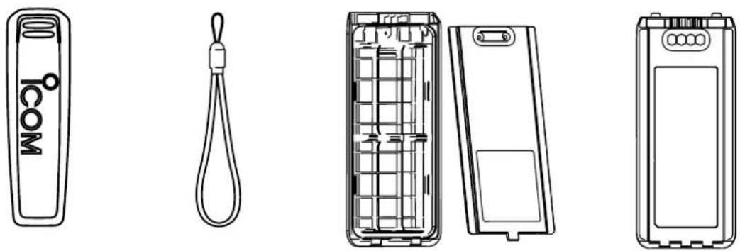
Supplied accessories
Antenna

Belt clip Handstrap Battery case* Battery pack
Headset adapter Power adapter* Battery charger*
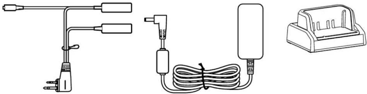
* May not be supplied, or the shape may be different, depending on the transceiver version.
Attaching accessories
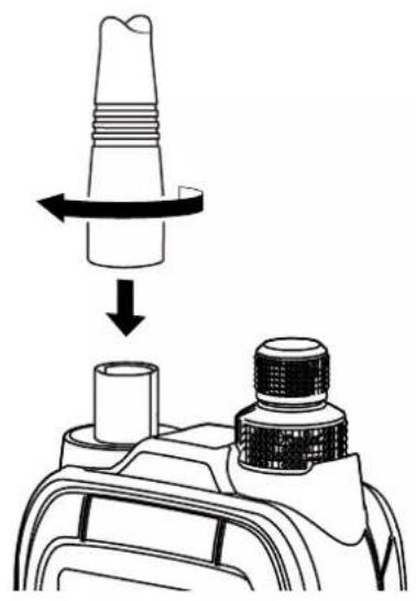
Antenna
Connect the supplied antenna to the antenna connector.
CAUTION:
- DO NOT carry the transceiver by holding only the antenna.
- DO NOT connect an antenna other than supplied antenna or those listed in this manual.
- Transmitting without an antenna may damage the transceiver.
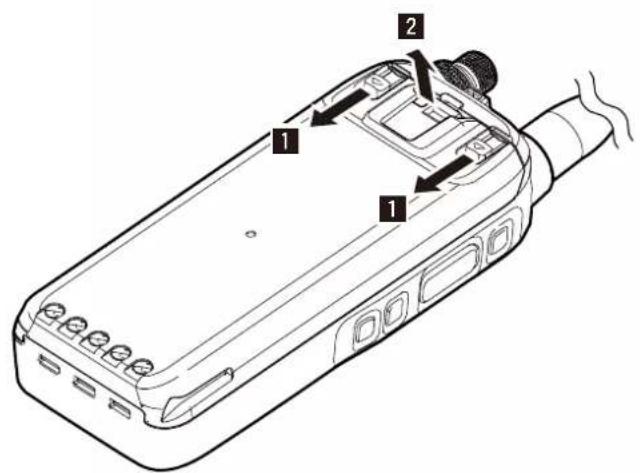
◇Battery pack/Battery case
CAUTION: DO NOT attach or detach the battery pack or the battery case when the transceiver is wet or soiled. This may result in water or dust getting into the transceiver, battery pack, or battery case and may damage the transceiver.
To attach:
- Slide the battery pack in the direction of the arrow. (①)
- Push the battery pack until the battery sliding locks make a 'click' sound. (②)
natural_image
Diagram showing a mechanical component with a rotating shaft and a base, no text or symbols present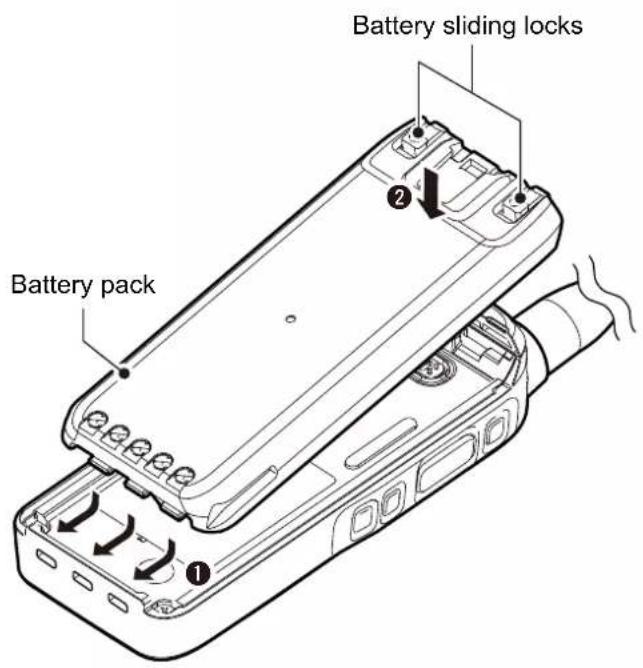
To detach:
- Pull both battery sliding locks in the direction of the arrow. (1)
• The battery pack is then released.
- Lift up to detach the battery pack. (2)
NOTE: Keep the battery pack terminals clean. It's a good idea to occasionally clean them.
1
ACCESSORIES ATTACHMENTS
Attaching accessories (Continued)
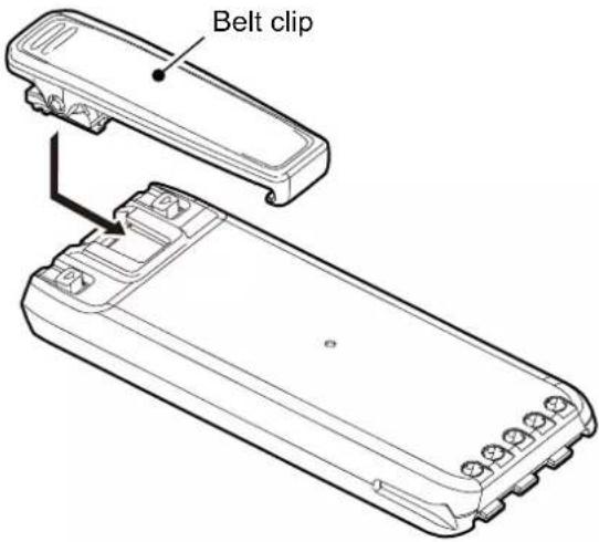
◇Belt clip
To attach:
- Remove the battery pack from the transceiver, if it is attached.
- Slide the belt clip in the direction of the arrow until the belt clip is locked and makes a 'click' sound.
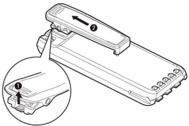
To detach:
Lift the tab up (①), and slide the belt clip in the direction of the arrow (②).
BE CAREFUL! Don't break your fingernail.
Headset connection
Connect your headset through the supplied headset adapter. Use the Side Tone function to output your transmitted voice to the headset ([MENU] > Sounds Settings > Side Tone). (p. 11-7)
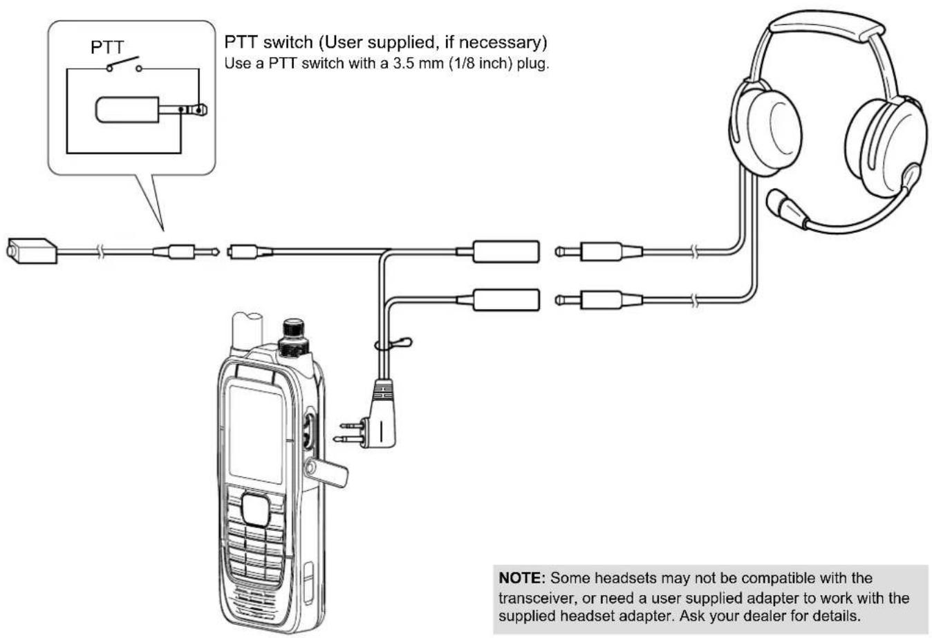
NOTE: Some headsets may not be compatible with the transceiver, or need a user supplied adapter to work with the supplied headset adapter. Ask your dealer for details.
Front, top and side panels (IC-A25C/IC-A25CE)*......2-2
Function display....2-3
con area 2-3
ext area ....2-3
Front, top and side panels (IC-A25C/IC-A25CE)\*
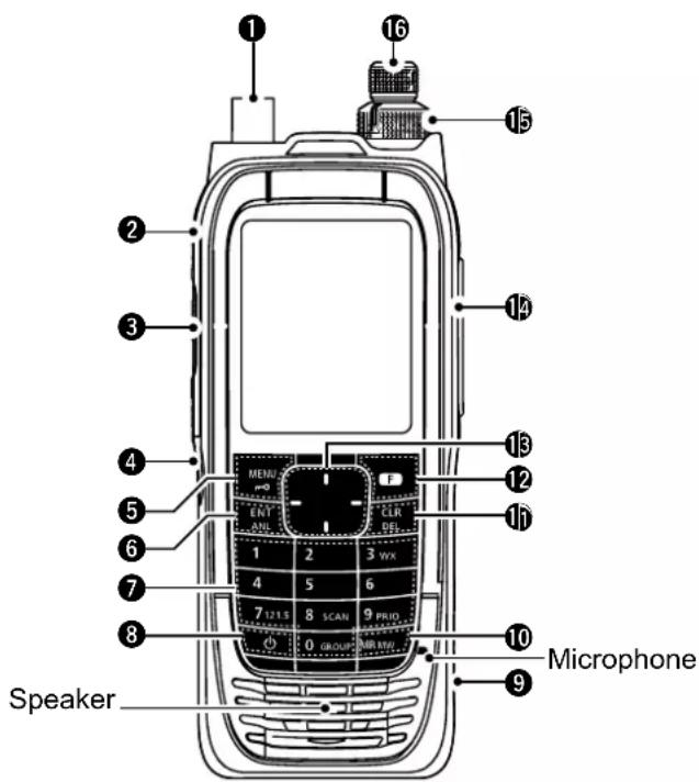
① ANTENNA CONNECTOR (p. 1-3)
Connect the supplied antenna.
② BACKLIGHT KEY [LIGHT]
Push to turn the backlight ON or OFF.
③ PTT SWITCH [PTT] (p. 4-2)
Hold down to transmit, release to receive.
④ SQUELCH ADJUSTMENT KEYS [SQL▲]/[SQL▼] (p. 4-2)
Push to adjust the squelch level.
⑤ MENU/LOCK KEY [MENU]/[→]
● Push to enter or exit the Menu screen.
- Push [F], and then push this key to lock the keypad.
⑥ ENTER/AUTOMATIC NOISE LIMITER KEY [ENT]/[ANL]
- Push to set the entered data, selected item, and so on.
- Push [F], and then push this key to turn the Automatic Noise Limiter (ANL) function ON or OFF. (p. 4-2)
⑦ TEN KEY*
- Push the keys to set the frequency, select a Memory channel, and so on.
- Push [F], and then push another key to use the secondary functions listed below.
WEATHER CHANNEL KEY [3]/[WX] (p. 9-3)
(For only the IC-A25N and IC-A25C)
Push to enter the Weather Channel Selection mode.
EMERGENCY KEY [7]/[121.5] (p. 4-3)
Push to select the emergency frequency.
SCAN KEY [8]/[SCAN] (p. 7-2)
Push to start a scan.
① Push [CLR] to stop a scan.
PRIORITY CHANNEL KEY [9]/[PRIO] (p. 9-2)
Push to turn the Priority Watch function ON or OFF. GROUP KEY [0]/[GROUP] (p. 4-2)
Push to display the "Group List" screen, to change the group in the memory mode.
8 POWER KEY [Φ]
Hold down for 1 second to turn the transceiver ON or OFF.
⑨ DC POWER JACK (p. 3-2)
- Connect the optional power adapter to charge the battery pack.
- Connect the optional cigarette lighter cable to use the transceiver with an external power source.
⑩ MEMORY/MEMORY WRITE KEY [MR]/[MW]
● Push to enter the Memory Channel Selection mode. (p. 4-2)
- Push [F], and then push this key to display the "Memory Write" screen, to write the set frequency to memory. (p. 8-6)
⑪ CLEAR/DELETE KEY [CLR]/[DEL]
- Push to cancel the entered data, selected item, exit the current mode, or return to the previous screen.
● While scanning, push to stop the scan. (p. 7-2) - Push [F], and then push this key to delete the selected Memory channel or Recall channel.
⑫ FUNCTION KEY [F]
Push this key, and then push another key within 3 seconds to use its secondary function.
⑬ DIRECTIONAL KEY
[UP]/[DOWN]/[LEFT]/[RIGHT]
- Push to select a Recall channel.
● Push to select a menu item, setting, and so on.
⑭ HEADSET JACK (p. 1-5)
Connects a third party headset through the supplied headset adapter.
⑮ VOLUME CONTROL KNOB [VOL]
Rotate to adjust the audio output level.
⑯ TUNING DIAL [DIAL]
Rotate to set the frequency, select a Memory channel, a menu item, and so on.
* There are some keys and functions for only the IC-A25N and IC-A25NE. See page 5-2 for details.
2
PANEL DESCRIPTION
Function display
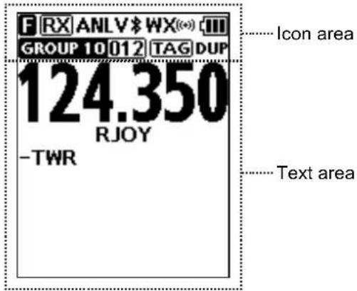
◇Icon area
Indicators
BATTERY INDICATOR
Displays the battery status.
| Battery status | Full Mid | Charging required | Battery exhausted | Charging | |
| Indication (Li-ion battery pack) | |||||
| Indication (Alkaline batteries) | |||||
GROUP/MEMORY INDICATOR GROUP 10012
Displays the selected group and channel in the Memory mode.
Icons
FUNCTION ICON F
Displayed for 3 seconds when you push [F] to use secondary functions assigned to a key.
RX/TX ICON RX TX
Displayed while receiving or transmitting.
AUTOMATIC NOISE LIMITER ICON ANL. 4-2)
Displayed when the Automatic Noise Limiter function is ON.
VOX ICON V
Displayed when the VOX function is ON.
Bluetooth® ICON \*(p. 10-2)
(For only the IC-A25N and IC-A25NE)
Displayed when a Bluetooth device is connected.
WX ICON (For only the IC-A25N and IC-A25C)
- “WX” is displayed when the transceiver is in the Weather Channel Selection mode. (p. 9-3)
● Displayed when the Weather Alert function is ON. - Blinks when a weather alert is received.
TAG ICON TAG
Displayed when a tagged channel is selected.
DUPLEX ICON D(HP 9-4)
(For only the IC-A25N and IC-A25NE)
Displayed when an NAV band frequency is selected with duplex setting* is ON, or duplex channel is selected.
^* ([MENU] > Radio Settings > Duplex Set) (p. 11-6)
◇Text area
● Displays the selected frequency, channel type, channel name, Priority channel, and so on.
Battery charger 3-2
Battery case 3-2
Battery charger
You can charge the supplied battery pack using the supplied battery changer and power adapter.
● Charging time: approximately 3 hours.
① You can also use the optional power adapter, instead of the supplied battery charger and power adapter.
* Charging time may be longer than using the supplied battery charger.
![Turn OFF [◎] Battery pack Power adapter* To the optional power adapter Battery charger*](/content/2026/05/950334/images/bf231a1b29e5473f391ca40c52f2b0e929b82f1cc647d99eecc0cbdea406b1df.jpg)
* May not be supplied, or the shape may be different, depending on the transceiver version.
NOTE:
- Before using the transceiver for the first time, the battery pack must be fully charged for optimum life and operation.
- Remove the transceiver from the charger or power supply when the battery pack has fully charged.
Battery case
When using the supplied battery case*, install 6 × AA (LR6) size Alkaline batteries, as shown below.
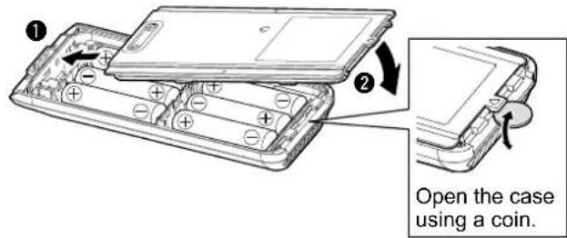
CAUTION:
- NEVER incinerate used battery cells since internal battery gas may cause them to rupture.
- NEVER expose a detached battery case to water. If the battery case gets wet, be sure to wipe it dry before using it.
- NEVER use batteries whose insulated cover is damaged.
NOTE:
- When installing the batteries, make sure they are all the same brand, type and capacity. Also, do not mix new and old batteries together.
- Keep the battery terminals clean. It's a good idea to occasionally clean them.
Receiving and transmitting 4-2
Setting the frequency 4-2
Receiving 4-2
Adjusting the squelch level....4-2
Using the Automatic Noise Limiter (ANL) function .....4-2
Transmitting....4-2
Selecting the 121.5 MHz emergency frequency......4-3
Selecting the Recall channels....4-3
Receiving and transmitting
◇Setting the frequency
① If the transceiver is in the Memory mode, push [CLR] to exit the Memory mode.
- Use the keypad to set the frequency.
Using dial:
- Push [F] and then rotate [DIAL] to set the MHz digit.
- F' is displayed while setting the MHz digit.
- Within 3 seconds*, Push [F] again, and then rotate [DIAL] to set the kHz digit.
•F" disappears.*
*“ F” automatically disappears in 3 seconds after [F] is pushed, or set the MHz digit.
○ Selecting a Memory channel
- Push [MR] to enter the Memory mode.
- The selected group and channel are displayed.
• Example GROUP 01 001
- Rotate [DIAL], or use the keypad to select a channel.
TIP: To change the selected group:
- Push [F], and then push [GROUP] to display the "Group List" screen.
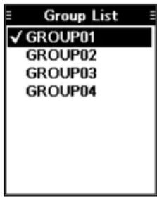
- Rotate [DIAL], to select a group, and then push [ENT].
◇Receiving
When receiving a signal, "RX" is displayed and audio is heard.
① Rotate volume control knob to adjust the audio output level.
![RX GROUP 01 [00] TAG 121.800 RJOY -GND](/content/2026/05/950334/images/d4d8d1913e1a6faffcbc5e87eabdd55c5f569be811d752113011fb98ac82e8c6.jpg)
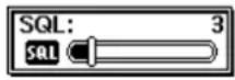
◇Adjusting the squelch level
- Push [SQL▲] or [SQL▼] to adjust the squelch level until the noise just disappears, when no signal is received.
- The adjustment screen is displayed while adjusting.
◇ Using the Automatic Noise Limiter (ANL) function
The function reduces noise components in the received signal, such as those caused by engine ignition systems.
- Push [F], and then push [ANL] to turn the function ON or OFF.
- "ANL" is displayed.
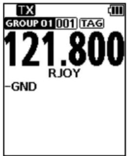
◇Transmitting
- Hold down [PTT], and then speak at your normal voice level.
- "TX" is displayed.
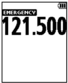
Selecting the 121.5 MHz emergency frequency
In case of emergency, you can immediately select the 121.5 MHz emergency frequency.
- Push [F], and then push [121.5] to select the emergency frequency.
① Push [CLR] to return to the previously selected frequency.
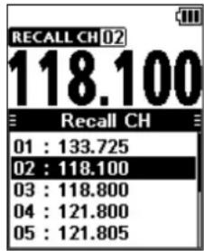
Selecting the Recall channels
The transceiver stores the previously selected frequencies in the “Recall CH.” You can easily select them without rotating [DIAL] or accessing memory.
-
Push the Directional key to display the "Recall CH" screen.
-
Select the channel.
-
The selected channel will be set in 3 seconds.
① It is not necessary to push [ENT] to select the channel.
① Push [CLR] to return to the previously selected frequency.
Keys used for Navigation Function 5-2
Course Deviation Indicator (CDI) screen....5-2
Using the Omni Bearing Selector (OBS)....5-2
Flying to a VOR station 5-3
Grosschecking position 5-4
Keys used for Navigation Function
The IC-A25N and IC-A25NE have the keys shown below to use the VOR Navigation function and Waypoint Navigation function.
- Push [F], and then push these keys to use the functions shown below.
① See section 6 for Waypoint Navigation function's details.
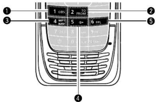
① OMNI BEARING SELECTOR [1]/[OBS]
Push to enter the Omni Bearing Selector (OBS) mode, to set the course heading.
② TO/FROM SELECTOR KEY [2]/[TO FROM]
Push to change the "TO/FROM" indicator and invert the OBS setting on the Course Deviation Indicator (CDI) screen.
③ WAYPOINT NAVIGATION KEY [4]/[WPT NAV]
Push to display the Waypoint Navigation screen.* *Only when a waypoint or a flight plan is selected.
④ DIRECT-TO KEY [5]/[6]
Push to display the "Direct-To WPT" screen, to enter a waypoint.
⑤ FLIGHT PLAN KEY [6]/[FPL]
Push to display the current flight plan.* *Only when a flight plan is selected.
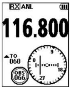
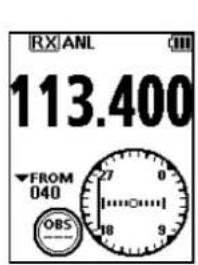
Course Deviation Indicator (CDI) screen
The transceiver displays the CDI screen when the NAV band frequency is selected.
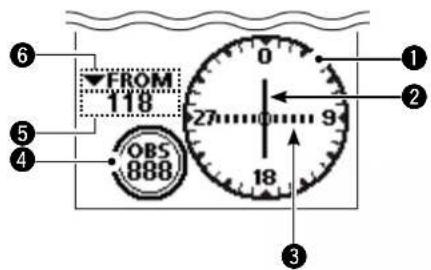
① COMPASS ROSE
② COURSE DEVIATION NEEDLE
Displayed when a VOR signal is received.
③ DEVIATION MARKS
④ OBS VALUE INDICATOR
Displays the course heading.
⑤ VOR VALUE INDICATOR
Displays the heading to or from a VOR.
⑥ TO/FROM INDICATOR
Using the Omni Bearing Selector (OBS)
Use the Omni Bearing Selector, as shown below, to set the course heading.
- Push [F], and then push [OBS] to enter the OBS mode.
• The OBS value is highlighted.
- Rotate [DIAL], or push keypad keys to set the course heading.
- Push [ENT] to save the adjusted course heading.
Flying to a VOR station
1. Select a VOR station's frequency.
• The CDI screen is displayed.
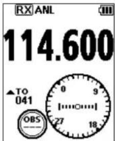
2. Push [F], and then push [OBS] to enter the OBS mode.
• The OBS value is highlighted.
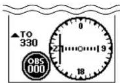
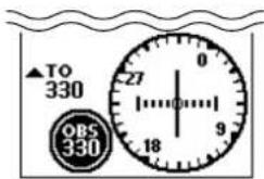
- The Course deviation is displayed, as shown below.
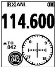
3. Push [ENT].
- Confirm the TO/FROM indicator displays "TO." • If "FROM" is displayed, push [F], and then push [TO FROM] to display "TO."
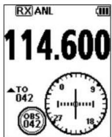
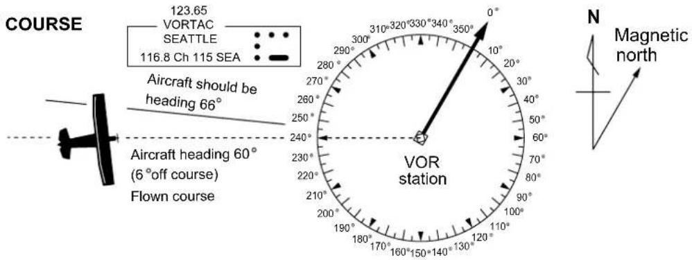
- Maintain the heading that the Course Deviation Needle comes to the center of CDI.
NOTE: The IC-A25N and IC-A25NE's VOR Navigation features are supplemental aids to navigation only, and are not intended to be a substitute for primary VOR navigation equipment.
TIP: Using the Auto Bearing Set System (ABSS): You can set your current heading as the course heading.
Example:
Your OBS course heading is set to 045. However, your current heading is 066 to the VOR. You want to set your current heading as the OBS course heading.
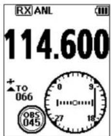
1. Push [F], and then push [TO FROM].
- "FROM 246" is displayed, and OBS is set to 246.
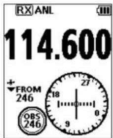
2. Push [F], and then push [TO FROM] again.
- "TO 066" is displayed, and OBS is set to 066.
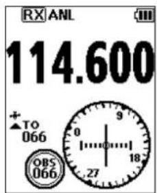
Flying to a VOR station (Continued)
THE AIRCRAFT IS ON COURSE
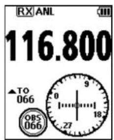
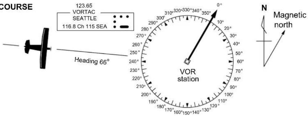
THE AIRCRAFT IS OFF COURSE
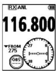
◇Crosschecking position
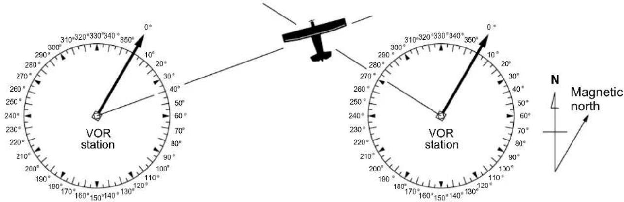
- Select 2 VOR stations on your aeronautical chart.
- Set one of the VOR station's frequency.
① Note the heading from the VOR displayed on the CDI screen.
- Set another VOR station's frequency.
① Note the heading from the VOR displayed on the CDI screen. - Extend the radials from each VOR station on the chart. Your aircraft is located at the point where the lines intersect.
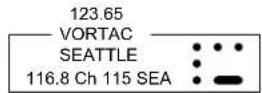
Waypoint Navigation screen 6-2
ison Area....6-2
Navigation Area....6-2
Selecting a waypoint....6-2
Selecting a waypoint from the memory 6-2
Selecting a waypoint from a flight plan....6-2
Selecting a waypoint near your position....6-2
Setting a waypoint manually ....6-3
Selecting a waypoint from history 6-3
Flying through a flight plan....6-3
Selecting a flight plan....6-3
Reversing a flight plan....6-3
Adding a flight plan....6-4
Managing Flight plan....6-4
Adding a flight plan....6-4
Editing a flight plan....6-5
Deleting a flight plan....6-5
The transceiver assists you to navigate to a selected destination, or follow your flight plan.
① The function works only when the transceiver's GPS receiver is receiving valid GPS signals.
NOTE: IC-A25N and IC-A25NE's Waypoint Navigation features are supplemental aids to navigation only, and are not intended to be a substitute for primary Waypoint Navigation equipment.
Waypoint Navigation screen
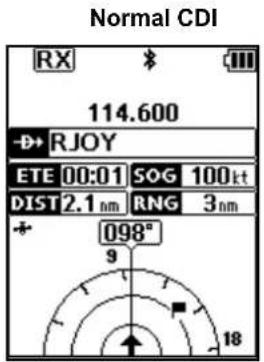
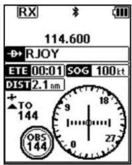
The transceiver has 2 types of Waypoint Navigation screens, as shown below. You can change the screen type on the "Navigation Style" screen.
([MENU] > WPT Navigation > Settings >
Navigation Style).
Normal type CDI type
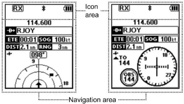
◇Icon Area
See page 2-3 for details.
◇Navigation Area
WAYPOINT NAME INDICATOR ➕RJOY
Displays the waypoint name.
① "FFL" is displayed, when a waypoint is selected from a flight plan.
Manual WPT is displayed, when the waypoint is manually selected.
ETE INDICATOR ETE 00:01
Displays the Estimated Time Enroute (ETE).
SOG INDICATOR SOG 100kt
Displays the Speed Over Ground (SOG).
DISTANCE INDICATOR DIST2.1 nm
Displays the distance to the destination.
RANGE INDICATOR RNG 3nm
(For only the Normal screen)
Displays the display range.
GPS ICON
- Displayed when valid position data is received.
- Blinks while searching for satellites or calculating position data.
HEADING INDICATOR 098°
(For only the Normal screen)
Displays your heading.
DESTINATION ICON (For only the Normal screen)
Displays the destination.
Selecting a waypoint
The transceiver assists you to navigate to a selected waypoint.
Select a waypoint to use as a destination, as shown below.
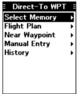
◇Selecting a waypoint from the memory
- Push [F], and then push [→] to display the "Direct-To WPT" screen.
- Select "Select Memory," and then push [ENT].
- The "Group List" screen is displayed.
- Select a group, and then push [ENT].
- Waypoints saved in the selected group are listed.
- Select a waypoint, and then push [ENT].
- The "Course To" screen is displayed.*
- Enter the course, and then push [ENT].*
- The Waypoint Navigation screen is displayed.
◇Selecting a waypoint from a flight plan
- Push [F], and then push [→] to display the "Direct-To WPT" screen.
- Select "Flight Plan," and then push [ENT].
- The "Flight Plan" screen is displayed.
- Select a flight plan, and then push [ENT].
- Waypoints included in the selected flight plan are displayed.
- Select a waypoint, and then push [ENT].
- The "Course To" screen is displayed.*
- Enter the course, and then push [ENT].*
- The Waypoint Navigation screen is displayed.
* The course entry is required only when the CDI type Navigation screen is selected.
Selecting a waypoint (Continued)
◇Selecting a waypoint near your position
- Push [F], and then push [→] to display the "Direct-To WPT" screen.
- Select "Near Waypoint," and then push [ENT].
- The transceiver searches for waypoints.
- The "Near Waypoint" screen is displayed, if waypoints are found.
- Select a waypoint, and then push [ENT]. • The "Course To" screen is displayed.*
- Enter the course, and then push [ENT].* The Waypoint Navigation screen is displayed.
◇Setting a waypoint manually
- Push [F], and then push [→] to display the "Direct-To WPT" screen.
- Select "Manual Entry," and then push [ENT]. The "Latitude" screen is displayed.
- Enter the latitude, and then push [ENT]. • The "Longitude" screen is displayed.
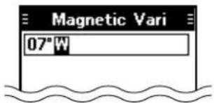
- Enter the longitude, and then push [ENT]. • The "Magnetic Vari" screen is displayed.
- Enter the magnetic variation, and then push [ENT]. • The "Course To" screen is displayed.*
- Enter the course, and then push [ENT].* The Waypoint Navigation screen is displayed.
◇Selecting a waypoint from history
- Push [F], and then push [→] to display the "Direct-To WPT" screen.
- Select "History," and then push [ENT]. The "History" screen is displayed.
- Select a waypoint, and then push [ENT]. • The "Course To" screen is displayed.*
- Enter the course, and then push [ENT].* The Waypoint Navigation screen is displayed.
Flying following a flight plan
The transceiver assists you to navigate following a selected flight plan.
◇Selecting a flight plan
- Open the "Select FPL" screen. ([MENU] > WPT Navigation > FPL Navigate > Select FPL) • Flight plans are displayed.
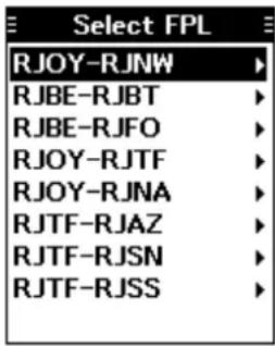
- Select a flight plan, and then push [ENT].
- Waypoints contained in the flight plan are displayed.
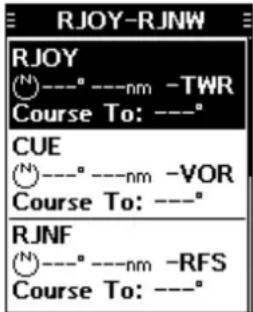
- Select a waypoint, and then push [ENT] to display the Waypoint Navigation screen. The transceiver starts to navigate to the next waypoint.
- Fly to the waypoint by checking the direction using the Waypoint Navigation screen.
NOTE:
When you come about 0.5 nm closer to the waypoint, the transceiver automatically starts navigating to the next waypoint.
① The function works only on the Nomal type Waypoint Navigation screen.
① You can turn OFF the function on the Menu screen. ([MENU] > WPT Navigation > Settings > Auto Change) When the function is OFF, push [F], and then push [FPL] to display the waypoints contained in the flight plan, and then select the next waypoint.
◇Reversing a flight plan
You can reverse the selected flight plan, to follow it back to the starting waypoint.
- After selecting a flight plan, select "Reverse Route," and then push [ENT].
- The transceiver starts to navigate to the next waypoint.
Managing Flight plans
You can edit, add, or delete flight plans on the "Manage FPL" screen.
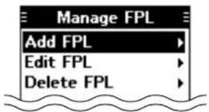
NOTE: You cannot edit, add, or delete flight plans when they are used in the Navigation function.*
Turn OFF the Navigation function before editing the flight plan.
([MENU] > WPT Navigation >
◇Adding a flight plan
- Open the "Add FPL" screen.
([MENU] > WPT Navigation > Manage FPL > Add FPL)
• The "Add FPL" screen is displayed.
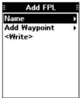
- Select "Name," and then push [ENT].
• The "Name" screen is displayed.
- Enter the name using keypad keys.
① Push [MENU] to return to the Main screen without making any changes.*
* A confirmation dialog is displayed.
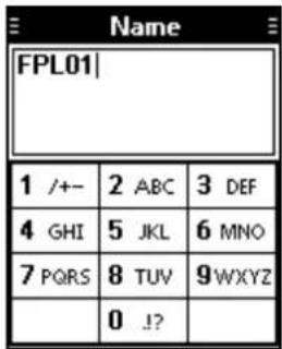
-
After editing, push [ENT] to return to the "Add FPL" screen.
-
Select "Add Waypoint," and then push [ENT]. The "Group List" screen is displayed.
-
Select a group, and then push [ENT]. • Waypoints saved in the selected group are listed.
-
Select a waypoint, and then push [ENT]. • The "Course To" screen is displayed.
-
Enter the course, and then push [ENT]. • The "Add FPL" screen is displayed.
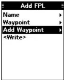
TIP:
Changing the waypoint order/ Deleting the added waypoint:
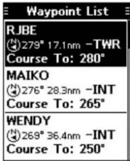
- Select "Waypoint," and then push [ENT]. The "Waypoint List" screen is displayed.
-
Select a waypoint.
-
Push [F], and then push [UP] or [DOWN] to change the selected waypoint. ① Push [F], and then push [DEL] to delete the selected waypoint.
-
Repeat steps 5 to 8 to add more waypoints, if necessary.
-
Select "
," and then push [ENT] to save the flight plan.*
*A confirmation dialog is displayed.
Managing Flight plans (Continued)
◇Editing a flight plan
- Open the "Edit FPL" screen.
([MENU] > WPT Navigation > Manage FPL > Edit FPL)
- The "Edit FPL" screen is displayed.
- Select a flight plan to edit, and then push [ENT].
- The screen shown below is displayed.
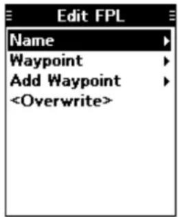
-
Edit the flight plan, as shown to the step 2 to 8 of the 'Adding a flight plan,' on the previous page.
-
Select "
," and then push [ENT] to save the flight plan.*
*A confirmation dialog is displayed.
◇Deleting a flight plan
- Open the "Delete FPL" screen.
([MENU] > WPT Navigation > Manage FPL > Delete FPL)
- The "Delete FPL" screen is displayed.
- Select a flight plan, and then push [ENT] to delete.*
*A confirmation dialog is displayed.
Using the Scan function 7-2
Scan types....7-2
FOX scan 7-2
Memory channel scan 7-2
Using the Scan function
1. Push [F], and then push [SCAN] to start a scan.
- "SCANNING" blinks while scanning.
① Rotate [DIAL] to change the scanning direction.
① When receiving a signal, the scan stops and "RX" is displayed.
① Rotate [DIAL] to resume the scan, even if a signal is received.
① When a signal is disappeared, the transceiver automatically resumes the scan in 3 seconds.
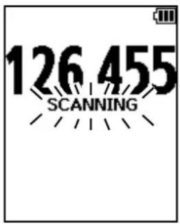
2. Push [CLR] to cancel the scan.
Scan types
The transceiver have any one type of scan function as shown below, depending on the presettings.
Ask your dealer for details.
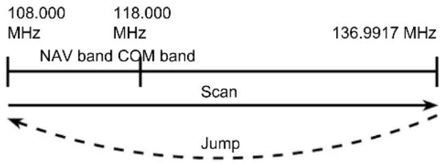
◇VFO scan
Repeatedly scans all frequencies over the entire band.
○ IC-A25N/IC-A25NE
The transceiver scans the COM and NAV bands.
① May not scans the NAV band, depending on the presettings. Ask your dealer for details.
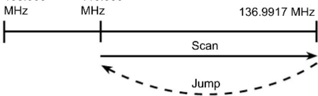
○ IC-A25C/IC-A25CE
The transceiver scans only the COM band.
108.000 118.000
◇Memory channel scan
○ Normal scan
Repeatedly scans tagged memory channels belonging to the same group.*
*Scans all memory channels, depending on the presetting.
① You can tag or untag a memory channel on the "TAG Set" screen.
([MENU] > Manage Memory > Edit Memory >
(Select a group) > (Select a channel) > TAG Set)
(p. 8-6)
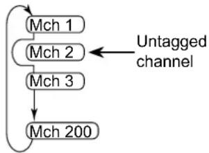
flowchart
graph TD
    A["Mch 1"] --> B["Mch 2"]
    B --> C["Mch 3"]
    C --> D["Mch 200"]
    E["Untagged channel"] --> B
○ Priority scan
While scanning, Priority watch checks for a signal on the selected Priority channel.
① You can select a priority channel on the "Priority CH" screen.
([MENU] > Radio Settings > Priority CH) (p. 9-2)
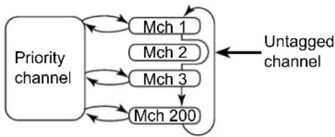
flowchart
graph TD
    A["Priority channel"] --> B["Mch 1"]
    A --> C["Mch 2"]
    A --> D["Mch 3"]
    A --> E["Mch 200"]
    B --> F["Untagged channel"]
    C --> F
    D --> F
    E --> F
Description....8-2
Editing a Memory channel....8-2
Memory channel name....8-3
Φype 8-3
Frequency 8-4
AG setting....8-4
Position 8-4
Group 8-5
Group name 8-5
Deleting a Memory channel....8-5
Editing the User Type....8-5
Saving contents into the Memory channels ....8-6
Saving a Waypoint 8-6
Saving a frequency 8-6
Description
The transceiver has 300 memories to save frequently used channels. You can assign the stored channel to up to 15 groups.
Following items are saved to each memory channel.
| Item Refer | to |
| Name | p. 8-3 |
| Type | p. 8-3 |
| Frequency | p. 8-4 |
| TAG Set | p. 8-4 |
| Position | p. 8-4 |
| Group | p. 8-5 |
| Group Name | p. 8-5 |
Editing Memory channels
You can edit the Memory channel contents, depending on the transceiver's presettings.
- Open the "Group List" screen.
([MENU] > Manage Memory > Edit Memory)
- The "Group List" screen is displayed.
- Select a group, and then select a Memory channel to edit.
- The "Edit Memory" screen is displayed
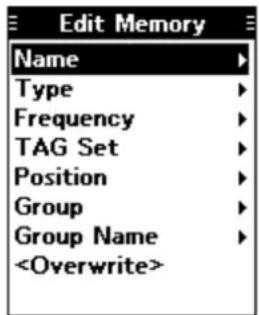
-
Select an item, and then push [ENT].
-
Edit the item.
① See the following pages for each item's details.
① Push [MENU] to return to the Main screen without making any changes.
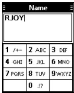
Example: Editing a Memory channel name
-
After editing, push [ENT] to return to the "Edit Memory" screen.
-
Select "
," and then push [ENT].*
* A confirmation dialog is displayed.
- Push [MENU] to return to the Main screen.
NOTE: You cannot edit a memory channel when it is used in the flight plan.*
Delete the memory channel from the flight plan before editing it. (p. 6-4)
* "Cannot edit. Memory is used in the Flight Plan." is displayed.
Editing memory channels (Continued)
◇Memory channel name
([MENU] > Manage Memory > Edit Memory > (Select a group) > (Select a channel) > Name)
Edit a memory channel name.
Usable characters are displayed on the screen.
① Push [DOWN] to select and enter the characters, as shown below.
| (space)~} | {` _^] \ [@?>=<;:/ . - , + *)(' & % $ # "! |
① Push [RIGHT] or [LEFT] to move the cursor.
| Name | ||
| RJOY| | ||
| 1 /+- | 2 ABC | 3 DEF |
| 4 GHI | 5 JKL | 6 MNO |
| 7 PQRS | 8 TUV | 9WXYZ |
| 0 !? | ||
◇Type
([MENU] > Manage Memory > Edit Memory > (Select a group) > (Select a channel) > Type)
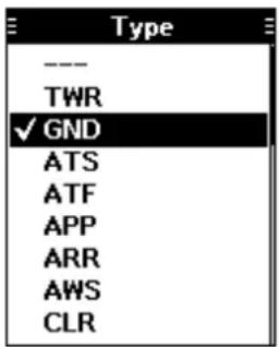
Select the type that indicates the type of equipment, as shown below.
| Item Type | |
| TWR Tower | |
| GND Ground | |
| ATS Automatic Terminal Information Service | |
| ATF Aerodrome Traffic Frequency | |
| APP Approach | |
| ARR Arrival | |
| AWS Automated Weather Observing System | |
| CLR Clearance | |
| CTF | Common Traffic Advisory Frequency |
| DEP | Departure |
| FSS | Flight Service Station |
| INT | Intersection |
| RFS Remote | Flight Service Station |
| UNI Unicom | |
| MF | Mandatory Frequency |
| VOR | VOR |
| OTH Other | |
| WPT Waypoint | |
| U-1/U-2 | You can edit these type names on the “User Type 1” or “User Type 2”screen. ([MENU] >Manage Memory > User type >User Type 1/User Type 2) (p. 8-5) |
Editing memory channels (Continued)
◇Frequency
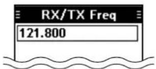
○ RX/TX frequency
Edit the RX/TX frequency if the Duplex function is OFF.
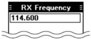
○ RX frequency
Edit the RX frequency if the Duplex function is ON.
① You can set only the NAV band frequency.
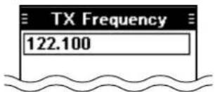
○ TX frequency
Edit the TX frequency if the Duplex function is ON.
① Set the flight service station's frequency.
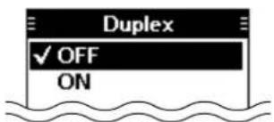
○ Duplex function
Duplex function enables you to call a flight service station while receiving an NAV band frequency.
(p. 9-4)
① This item is displayed for all versions. However, it may be usable only in the USA.
OFF: Enter the RX/TX frequency.
ON: Enter the RX and TX frequencies.
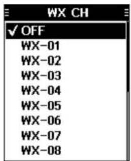
○ Weather channel
(For only the IC-A25N and IC-A25C)
Select a weather channel.
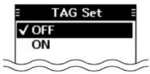
◇TAG setting
( Displayed only when a frequency is entered, or a weather channel is selected)
([MENU] > Manage Memory > Edit Memory > (Select a group) > (Select a channel) > TAG Set)
Select whether or not to tag the memory channel.
OFF: The channel is skipped while scanning.
ON: The channel is scanned while scanning.
◇Position
(For only the IC-A25N and IC-A25NE)
([MENU] > Manage Memory > Edit Memory > (Select a group) > (Select a channel) > Position)
Edit the memory channel's position data.
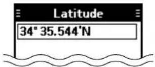
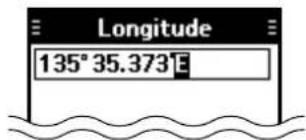
○ Latitude
Edit the latitude.
○ Longitude
Edit the longitude.
○ Magnetic variation
Edit the magnetic variation.
Editing memory channels (Continued)
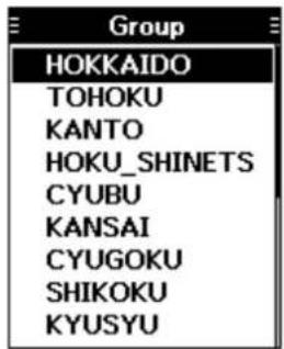
◇Group
([MENU] > Manage Memory > Edit Memory > (Select a group) > (Select a channel) > Group)
Select a group that the memory channel belongs to.
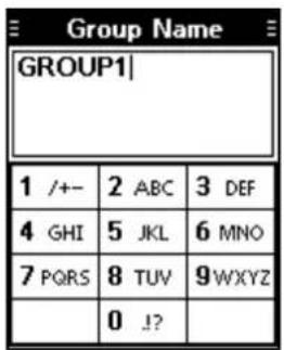
◇Group name
([MENU] > Manage Memory > Edit Memory > (Select a group) > (Select a channel) > Group Name)
Edit the group name that the memory channel belongs to.
Deleting a Memory channel
You can delete unwanted memory channels.
-
Select a memory channel to delete. ([MENU] > Manage Memory > Delete Memory)
-
Push [ENT] to delete the channel.*
* A confirmation dialog is displayed.
NOTE: You cannot delete the memory channel when it is used in the flight plan.*
* "Cannot delete. Memory is used in the Flight Plan." is displayed.
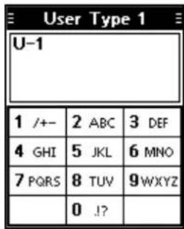
Editing the User Type
You can edit the type names "U-1" and "U-2" that represent the Memory channel type. (p. 8-3)
- Open the "User Type 1" or "User Type 2" screen. ([MENU] > Manage Memory > User Type > User Type 1/User Type 2)
- The "User Type 1" or "User Type 2" screen is displayed.
-
Edit the user type. You can enter a maximum of 3 characters.
-
After editing, push [ENT] to return to the "User Type" screen.
-
Push [MENU] to return to the Main screen.
Saving contents into the Memory channels
You can save contents to the memory channels, depending on the transceiver's presettings.
◇Saving a Waypoint
(For only the IC-A25N and IC-A25NE)
Save your current position as a Waypoint.
- Open the "Add Waypoint" screen.
([MENU] > WPT Navigation > Add Waypoint)
- The current position is displayed, if a GPS signal is received.
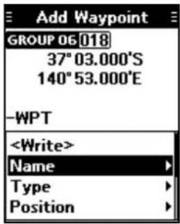
- Select and edit the items shown below, if necessary.
| Item Refer to | |
| Name | p. 8-3 |
| Type | p. 8-3 |
| Position | p. 8-4 |
| Group | p. 8-5 |
| Group Name | p. 8-5 |
-
Select "
," and then push [ENT].* *A confirmation dialog is displayed. -
Push [MENU] to return to the Main screen.
◇Saving a frequency
Save the selected frequency.
-
Set a frequency to save.
-
Push [F], and then push [MW].
- The "Memory Write" screen is displayed.
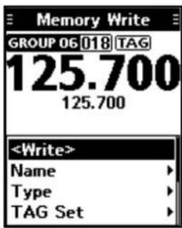
- Select and edit the items shown below, if necessary.
| Item Refer to | |
| Name | p. 8-3 |
| Type | p. 8-3 |
| TAG Set | p. 8-4 |
| Position | p. 8-4 |
| Group | p. 8-5 |
| Group Name | p. 8-5 |
- Select "
," and then push [ENT].*
① Push [CLR] to return to the Main screen without making any changes.
*A confirmation dialog is displayed.
- Push [MENU] to return to the Main screen.
Priority watch....9-2
Setting the Priority channel 9-2
Using the Priority Watch function 9-2
Using a weather channel
(For only the IC-A25N and IC-A25C)....9-3
Selecting a Weather channel 9-3
Receiving a Weather Alert....9-3
Scanning Weather channels 9-3
Weather channel tag settings....9-3
Using the Duplex function
(For only the IC-A25N and IC-A25NE)....9-4
Using the Duplex function 9-4
Priority watch
The transceiver monitors a channel set as the Priority channel, while another frequency or memory channel is selected.
◇Setting the Priority channel
- Open the "Priority CH" screen.
([MENU] > Radio Settings > Priority CH)
- The channel set as the Priority channel is displayed. - "OFF" is displayed if no channel is set as the Priority channel.
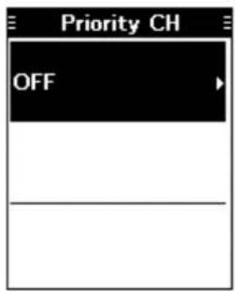
- Push [ENT].
- "Group List" is displayed.
- Select the channel to set as the Priority channel, and then push [ENT].
• The selected channel is set as the Priority channel.
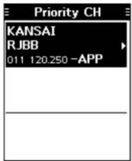
- Push [MENU] to return to the Main screen.
◇Using the Priority Watch function
- Push [F], and then push [PRIO] to turn ON the function.
- The Priority channel is displayed at the bottom of the screen.
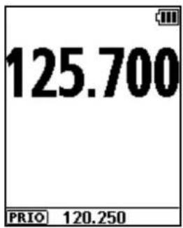
① When a signal is received on the Priority channel, it is displayed at the top of the screen.
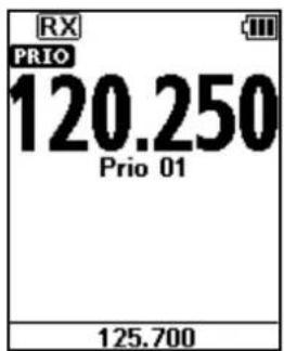
Using a Weather channel (For only the IC-A25N and IC-A25C)
The transceiver has 10 preset Weather channels. You can use these channels to monitor broadcasts from the National Oceanographic and Atmospheric Administration (NOAA). The transceiver automatically detects a Weather alert tone on the selected Weather channel, or while scanning.
◇Selecting a Weather channel
- Push [F], and then push [WX] to enter the Weather Channel Selection mode.
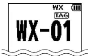
- Rotate [DIAL], or push keypad keys to select a Weather channel.
① Push [CLR] to return to the Main screen.
◇Receiving a Weather Alert
The transceiver receive a Weather alert, if the Weather Alert function is ON.
- Open the "Weather Alert" screen. ([MENU] > Radio Settings > Weather Alert)
- The "Weather Alert" screen is displayed.
-
Select "ON," and then push [ENT].
-
Push [MENU] to return to the Main screen.
- When the alert is received, "WX" and "ALT" alternately blink.
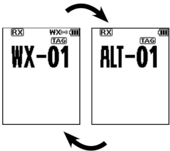
NOTE: When the Weather Alert function is ON, the transceiver checks Weather channels, even if a channel other than a Weather channel is selected.*
*Except when the Priority Watch function is working.
◇Scanning Weather channels
- Push [F], and then push [WX] to enter the Weather Channel Selection mode.
- Push [F], and then push [SCAN] to start the scan.
- "SCANNING" blinks while scanning.
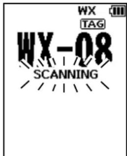
① Rotate [DIAL] to change the scanning direction.
① When receiving a signal, the scan stops and the "RX" is displayed.
① Rotate [DIAL] to resume the scan, even while a signal is received.
① When a signal disappears, the transceiver automatically resumes the scan after 3 seconds.
- Push [F], and then push [SCAN] again to cancel the scan.
◇Weather channel tag settings
You can untag each Weather channel on the "WX CH TAG Set" screen. The untagged channels will not be scanned.
- Open the "WX CH TAG Set" screen.
([MENU] > Radio Settings > WX CH TAG Set) - The "WX CH TAG Set" screen is displayed.
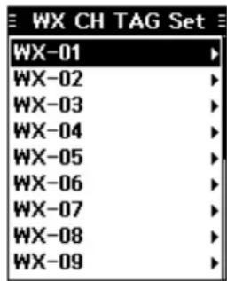
- Select a channel, and then push [ENT].
- Select "OFF," and then push [ENT].
- Push [MENU] to return to the Main screen.
Using the Duplex function (For only the IC-A25N and IC-A25NE)
The duplex function enables you to call a flight service station while receiving a VOR frequency. Turn ON the function, and set the flight service station's frequency on the Menu screen.
NOTE: This function is usable for all versions, However, flight service stations may be available only in North America.
1. Turn ON the Duplex setting
- Open the "Duplex Set" screen. ([MENU] > Radio Settings > Duplex Set)
- The "Duplex Set" screen is displayed.
- Select "ON," and then push [ENT]. The "Radio Settings" screen is displayed.
2. Setting the Duplex TX frequency
- Open the "Duplex TX Freq" screen. ([MENU] > Radio Settings > Duplex TX Freq)
- The "Duplex TX Freq" screen is displayed
- Push keypad keys to set the flight service station's frequency, and then push [ENT].
- The "Radio Settings" screen is displayed.
- Push [MENU] to return to the Main screen.
◇Using the Duplex function
- Set the VOR frequency.
- Hold down [PTT] to transmit on the frequency set on the "Duplex TX Freq" screen.
- The Duplex TX frequency is displayed while holding down [PTT].
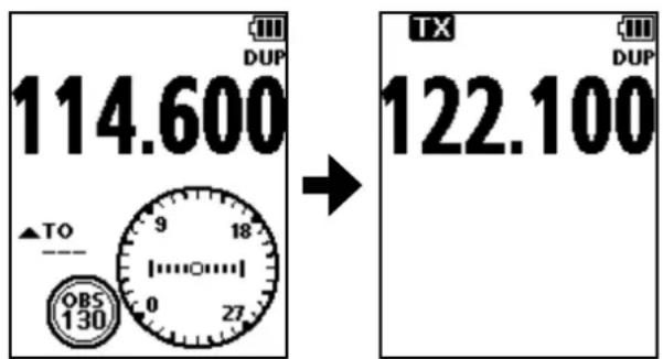
3. Release [PTT] to return to receive.
TIP: You can use the Duplex function in the Memory mode, if the function is enabled in the selected Memory channel. See page 8-4 for details of the Memory channel's Duplex settings.
Operating Bluetooth....10-2
Electromagnetic Interference....10-2
Pairing with a device....10-2
Pairing with a Low Energy device....10-3
Disconnecting a paired device....10-3
Unpairing a device....10-3
Bluetooth settings....10-3
Bluetooth module specifications....10-3
Operating Bluetooth
The IC-A25N and IC-A25NE have a built-in Bluetooth unit. You can connect Bluetooth headsets, or other Bluetooth devices to use some of navigation functions.
The communication range of Bluetooth is approximately 10 meters (33 ft).
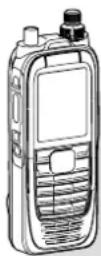
IC-A25N or IC-A25NE
Bluetooth®
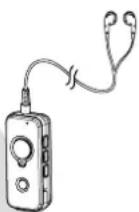
Bluetooth headset
(Example: Optional VS-3)
NOTE:
- The Bluetooth communication range may vary, depending on the environment where you operate the device.
- The key beep sound may distorts when using the transceiver with a Bluetooth headset. Reduce the key beep level to prevent the distortion.
([MENU] > Sounds Settings > Beep)
You cannot switch the optional VS-3 Bluetooth headset to other devices, if the VOX level is set to 6. ([MENU] > Radio Settings > VOX Level)
Electromagnetic Interference
When you use a Bluetooth device, pay attention to the following:
Bluetooth devices operate in the 2.4 GHz band. The 2.4 GHz band is also used by other devices, such as Wireless LAN products, microwave ovens, RFID systems, amateur radio stations, and so on.
When using this device near such devices, interference may occur, causing a decrease in communication speed, and an unstable connection. In such cases, use this device away from the other devices, or stop using those devices.
Pairing with a device
You can pair Bluetooth headsets and data devices to the transceiver, as shown below:
- A maximum of 5 Bluetooth headsets and data devices.
- A maximum of 2 Low Energy (LE) devices.
① These instructions describe pairing with the VS-3 Bluetooth® headset, as an example.
1. Turning ON the transceiver's Bluetooth function
- Push [MENU].
- Select "Bluetooth Set," and then push [ENT]. (Bluetooth > Settings > Bluetooth Set)
- Select "ON," and then push [ENT].
- Push [MENU] to return to the Main screen.
2. Entering the VS-3 Pairing mode
Refer to the VS-3's instruction manual for details.
3. Pairing and connecting the Bluetooth headset
- Push [MENU].
- Select "Search Device," and then push [ENT].
(Bluetooth > Pairing/Connect > Search Device)
① The transceiver cannot search for a new headset or device if it is connected with more than 2 headsets or devices. - Select "Headset."
• The transceiver searches for a headset.
① Push [CLR] to cancel searching. - Select the headset to pair, and then push [ENT].
① “No Device Found” is displayed if no headsets or devices are found.
① A passkey or PIN code may be required to pair, depending on the headset or device. Refer to your headset or device's instructions for details.
① The headset or device name changes to its Bluetooth device address in 5 seconds.
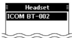

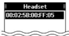
- Push [MENU] to return to the Main screen.
•” is displayed if the headset or device is correctly connected.
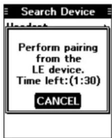
Pairing with a Low Energy device
Pair a Low Energy (LE) device, as shown below.
- Push [MENU].
- Select "LE Device," and then push [ENT].
( Bluetooth > Pairing/Connect > Search Device
LE Device)
- Perform pairing from the LE device within 2 minutes.
① The remaining time is displayed.
Disconnecting a paired device
You can disconnect a paired Bluetooth device if it is not used.
- Push [MENU].
- Select "Pairing/Connect."
(Bluetooth > Pairing/Connect)
- Paired devices are displayed.
① “(Connect)” is displayed, if a device is connected.
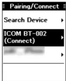
- Select a device to disconnect, and then push [ENT].
- The screen shown below is displayed.
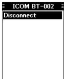
- Push [ENT].*
*A confirmation dialog is displayed. - Push [MENU] to return to the Main screen.
Unpairing a device
Before unpairing a connected headset or device, disconnect it.
- Push [MENU].
- Select "Pairing/Connect."
(Bluetooth > Pairing/Connect)
- Paired devices are displayed.
- Select a device to disconnect, and then push [ENT].
- The screen as shown below is displayed.
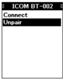
- Select "Unpair," and then push [ENT].*
*A confirmation dialog is displayed. - Push [MENU] to return to the Main screen.
Bluetooth settings
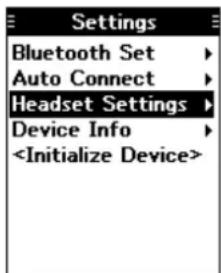
You can customize the Bluetooth settings on the "Settings" screen. (p. 11-5)
Bluetooth module specifications
• Frequency range: 2402 \~ 2480 MHz
• Transmission power: 4 dBm (Typical)
- Version: 4.2
• Support profile: HFP, HSP, SPP, HRP, GATT (GATT over Serial)
Using the Menu screen....11-2
Search Near ST....11-2
WPT Navigation 11-2
WPT NAV OFF> 11-2
WPT NAV Disp>......11-2
Direct-To WPT 11-2
EPL Navigate....11-3
Add Waypoint....11-3
Manage FPL....11-3
GPS Status 11-3
GPS Info....11-3
Settings 11-4
Bluetooth....11-4
Bairing/Connect....11-4
Settings 11-5
Manage Memory 11-6
Edit Memory 11-6
Delete Memory....11-6
Radio Settings 11-6
Time Out Timer....11-6
Weather Alert
(For only the IC-A25N and IC-A25C)....11-6
WX CH TAG Set
(For only the IC-A25N and IC-A25C)....11-6
Duplex Set....11-6
Duplex TX Freq 11-6
FOX Set 11-6
FOX Delay 11-6
FOX Level 11-6
Priority CH....11-6
Display Settings....11-7
Backlight....11-7
Contrast....11-7
Night Mode....11-7
Units 11-7
Sounds Settings....11-7
Beep....11-7
Side Tone 11-7
Others....11-7
Battery Status....11-7
Version 11-7
Using the Menu screen
You can use the Menu screen to set infrequently changed values or function settings.
The Menu screen is constructed in a tree structure. You can go to the next tree level with [RIGHT] or [ENT], go back a level with [LEFT] or [CLR]. To select an item, rotate [DIAL] or push [UP] or [DOWN].
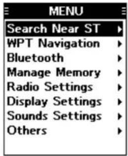
NOTE: The menu items contained in the transceiver may be different, depending on the transceiver's version or presettings. Ask your dealer for details.
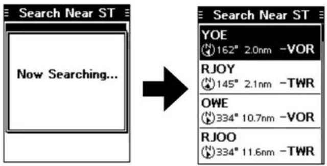
Search Near ST (For only the IC-A25N and IC-A25NE)
([MENU] > Search Near ST)
Search for near stations.
① The function works only when the transceiver's GPS receiver is receiving valid GPS signals.
WPT Navigation
(For only the IC-A25N and IC-A25NE)
◇
([MENU] > WPT Navigation >
Cancel the Waypoint Navigation.
① Not displayed, when the Waypoint Navigation function is not used.
◇
([MENU] > WPT Navigation >
Display the Waypoint Navigation screen.
① Not displayed, when the Waypoint Navigation function is not used.
◇Direct-To WPT
([MENU] > WPT Navigation > Direct-To WPT)
Select a waypoint to use as a destination.(p. 6-2)
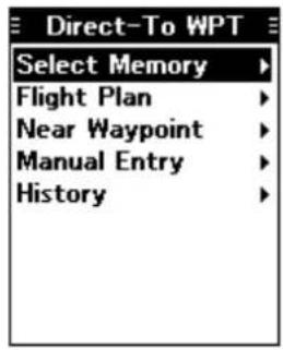
○ Select Memory
Select a waypoint from memory.
○ Flight Plan
Select a waypoint from a Flight Plan.
○ Near Waypoint
Select a waypoint near your current location.
① The function works only when the transceiver's GPS receiver is receiving valid GPS signals.
○ Manual Entry
Set a waypoint manually, by entering latitude, longitude, and magnetic variation.
O History
Select a waypoint from history.
WPT Navigation (Continued)
◇FPL Navigate
([MENU] > WPT Navigation > FPL Navigate)
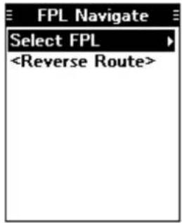
○ Select FPL
Select a flight plan to follow. (p. 6-3)
○
Reverse the selected flight plan. (p. 6-3)
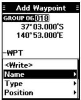
◇Add Waypoint
([MENU] > WPT Navigation > Add Waypoint)
Save your current position as a Waypoint.
◇Manage FPL
([MENU] > WPT Navigation > Manage FPL) Add, edit, or delete a flight plan.
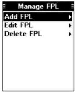
○ Add FPL
Add a flight plan. (p. 6-4)
○ Edit FPL
Edit a flight plan. (p. 6-5)
○ Delete FPL
Delete a flight plan. (p. 6-5)
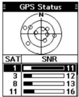
◇GPS Status
([MENU] > WPT Navigation > GPS Status) Displays the GPS Status.
◇GPS Info
([MENU] > WPT Navigation > GPS Info)
Displays the data received by the built-in GPS receiver.
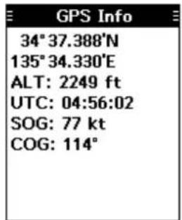
NOTE: The altitude data received by the built-in GPS receiver is for reference only, and not intended to be a substitute for a primary altitude indicator.
WPT Navigation (Continued)
◇Settings
([MENU] > WPT Navigation > Settings)
Edit GPS, Navigation Style, and Auto Change settings.
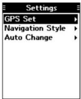
○ GPS Set
Turn the built-in GPS receiver ON or OFF.
• OFF: Turn OFF the receiver.
• ON: Turn ON the receiver.
○ Navigation Style
Select a type of Waypoint Navigation screen.
○ Auto Change
Turn the Auto Change function ON or OFF.
The function is used when you following a flight plan on the Normal Waypoint Navigation screen. (p. 6-3)
• OFF: The next destination is not automatically selected. You have to manually select the next waypoint.
- ON: The next destination is automatically selected when your plane has arrived a waypoint.
Bluetooth
(For only the IC-A25N and IC-A25NE)
◇Pairing/Connect
([MENU] > Bluetooth > Pairing/Connect)
Displays the paired Bluetooth headsets and Bluetooth data devices.
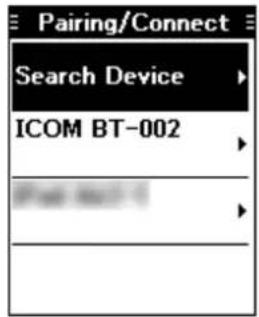
○ Search Device
Search for a Bluetooth headset, data device, or Low Energy (LE) device to pair and connect.
• Headset: Search for a Bluetooth headset.
• Data Device: Search for a Bluetooth data device.
- LE Device: Display a dialog to perform pairing from the LE device.
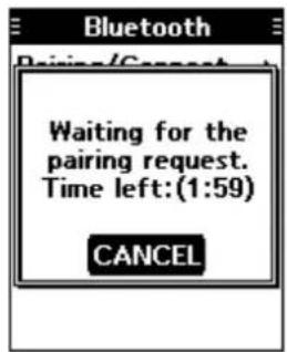
◇
([MENU] > Bluetooth >
Wait for the pairing request from a Bluetooth headset or data device.
Bluetooth (Continued)
◇Settings
([MENU] > Bluetooth > Settings)
Edit Bluetooth settings.
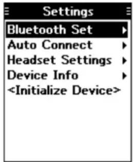
○ Bluetooth Set
Turn the Bluetooth function ON or OFF.
- OFF: Turns OFF the function.
• ON: Turns ON the function.
○ Auto Connect
Select whether or not to automatically connect to the last bonded Bluetooth device.
- OFF: The user must manually connect to the bonded device.
- ON: Automatically connects to the last bonded device.
○ Headset Settings
Edit Bluetooth headset settings.
- AF Output
Select the AF Output device for when the Bluetooth headset is connected.
- HS Only: Sets the headset as the AF Output device.
- HS & SP: Sets the headset and the transceiver's speaker as the AF Output devices.
- Headset Function
Select the Headset operation.
- Normal: Transmits the audio from the device whose [PTT] is pushed.
- MIC Transmits the audio from only the Bluetooth headset.
Transmission is made by pushing either the [PTT] on the Bluetooth headset, on the aviation headset*, or on the hand microphone*.
* Used for only PTT control.
- PTT (Main MIC): Transmission is made by pushing [PTT] only on the Bluetooth headset. Transmits the audio from the hand microphone
- PTT (Main HS): Transmission is made by pushing [PTT] only on the Bluetooth headset. Transmits the audio from the aviation headset.
- Icom Headset
Power Save:
Select whether or not to operate with the Bluetooth headset's battery saving mode while the optional VS-3 Bluetooth® HEADSET is connected.
- OFF: The Power Save mode is OFF.
- ON: The Power Save mode is activated when there is no communication or operation for 120 seconds.
One-touch PTT:
Set the One-Touch PTT function while the optional VS-3 Bluetooth® HEADSET is connected.
The function enables you to communicate with a single push of the VS-3's [PTT].
- OFF: Push [PTT] to transmit and release to receive.
- ON: Push [PTT] to transmit and push again to receive.
PTT Beep:
Set the beep sound when pushing [PTT] on the optional VS-3 Bluetooth® HEADSET.
- OFF: No beep sounds when pushing PTT.
• ON: A beep sounds when pushing PTT.
Device Info
Displays the device information.
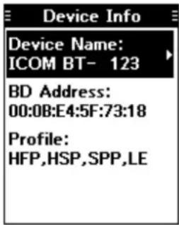
- Device Name:
Edit the device name.
○
Initialize the built-in Bluetooth unit and restart the transceiver.*
* A confirmation dialog is displayed.
Manage Memory
◇Edit Memory
([MENU] > Manage Memory > Edit Memory) Edit the Memory channel contents. (p. 8-2)
◇Delete Memory
([MENU] > Manage Memory > Delete Memory) Delete an unwanted memory channel. (p. 8-5)
○ User Type 1/User Type 2
Edit the type names ("U-1" and "U-2") that represent the Memory channel type. (p. 8-3)
Radio Settings
◇Time Out Timer
([MENU] > Radio Settings > Time Out Timer) Turn the Time Out Timer (TOT) function ON or OFF. This function limits continuous transmissions on the channel, to prevent from occupying the channel for a long period of time.
- OFF: Turns OFF the function.
- 20 sec to 180 sec: Set the Time-out Timer to between 20 seconds and 180 seconds.
◇Weather Alert
(For only the IC-A25N and IC-A25C)
([MENU] > Radio Settings > Weather Alert) Turn the Weather Alert function ON or OFF. This function detects the weather alert tone on Weather channels. The National Oceanic and Atmospheric Administration (NOAA) broadcast station transmits a weather alert tone before any important weather information. (p. 9-3)
- OFF: The transceiver does not detect a Weather alert tone.
- ON: The transceiver detects the 1050 Hz weather alert tone on a Weather channel or on the previously selected Weather channel while scanning.
◇WX CH TAG Set
(For only the IC-A25N and IC-A25C)
([MENU] > Radio Settings > WX CH TAG Set)
Select whether or not to tag each Weather channel. (p. 9-3)
OFF: The channel is skipped while scanning.
ON: The channel is scanned while scanning.
◇Duplex Set
([MENU] > Radio Settings > Duplex Set)
Select whether or not to use the Duplex function. (p. 9-4)
① This item is displayed for all versions. However, it may be usable only in the USA.
- OFF: Turns OFF the function.
- ON: You can call a flight service station while receiving an NAV band frequency.
◇Duplex TX Freq
([MENU] > Radio Settings > Duplex TX Freq) Enter the transmit frequency when the Duplex function is ON.
◇VOX Set
([MENU] > Radio Settings > VOX Set) Turn the VOX function ON or OFF. The function automatically switches between receive and transmit by detecting your voice.
• OFF: Turns OFF the function.
- ON: Switches between receive and transmit by detecting your voice.
◇VOX Delay
([MENU] > Radio Settings > VOX Delay) Set the VOX Delay to between 0.5 sec and 3.0 sec. The VOX Delay is the amount of time the transmitter stays ON after you stop speaking until the VOX switches to receive.
◇VOX Level
([MENU] > Radio Settings > VOX Level) Set the VOX gain level to between 1 and 6. Higher values make the VOX function more sensitive to your voice.
NOTE: You cannot switch the optional VS-3 Bluetooth headset to other devices, if the VOX level is set to 6.
◇Priority CH
([MENU] > Radio Settings > Priority CH) Set the Priority channel. (p. 9-2)
Display Settings
◇Backlight
([MENU] > Display Settings > Backlight)
Set the LCD backlight brightness to "Dark" or "Bright."
◇Contrast
([MENU] > Display Settings > Contrast)
Set the LCD contrast level to between 1 (lowest) and 10 (highest).
◇Night Mode
([MENU] > Display Settings > Night Mode)
Set the LCD display mode to the Day Mode or Night Mode.
OFF: The function display works in the Day Mode.
ON: The function display works in the Night Mode.
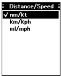
Units
([MENU] > Display Settings > Units)
○ Distance/Speed
Select a format to display the distance and speed.
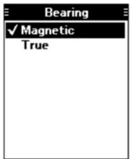
○ Bearing
Select a format to display the bearing.
Sounds Settings
◇Beep
([MENU] > Sounds Settings > Beep)
Set the beep output level to between 1 (lowest) and 10 (highest), or OFF.
◇Side Tone
([MENU] > Sounds Settings > Side Tone)
Set the side tone output level to between 1 (lowest) and 10 (highest), or OFF.
The Side tone function outputs the transmitting audio to the headset connected to the transceiver.
NOTE:
When using the optional HM-231 HAND MICROPHONE, set the side tone output level to OFF. Otherwise, your voice will be heard from the speaker while transmitting.
Others
◇Battery Status
([MENU] > Others > Battery Status)
Displays the battery status.
◇Version
([MENU] > Others > Version)
Displays your transceiver's CPU, Bluetooth unit, and GPS unit version.
Specifications....12-2
General 12-2
Transmitter 12-2
Receiver 12-3
Options....12-3
Battery pack/Battery case 12-3
Charger 12-3
Antenna....12-3
Belt clip and belt hangers....12-3
Others 12-3
12 SPECIFICATIONS AND OPTIONS
Specifications (Measurements made without an antenna.)
All stated specifications are subject to change without notice or obligation.
◇General
- Frequency range:
IC-A25N/IC-A25NE TX 118.000 \~ 136.99166 MHz
RX 108.000 \~ 136.99166 MHz
WX 161.650 \~ 163.275 MHz
IC-A25C/IC-A25CE TX 118.000 \~ 136.99166 MHz
RX 118.000 \~ 136.99166 MHz
WX 161.650 \~ 163.275 MHz
• Channel spacing: 25 kHz/8.33 kHz
- Mode:
IC-A25N/IC-A25C 6K00A3E/5K60A3E (FCC/EXP), 6K00A3E (Industry Canada)
16K0G3E (WX)
IC-A25NE/IC-A25CE 6K80A3E/5K00A3E
• Number of memory channels: 300 channels
- Antenna impedance: 50 Ω nominal
- Antenna connector: BNC type
• Power supply requirement: 7.2 V DC standard or 11.0 V DC at the external DC jack
- Current drain: TX Less than 1.8 A RX 90 mA typical (at standby), Less than 500 mA (at AF maximum) ^*2
- Operating temperature range:
IC-A25N/IC-A25C -10^ to +60^ , 14^ to 140^
IC-A25NE/IC-A25CE -20°C to +55°C
- Dimensions (projections not included): 58.9 (W) × 148.4 (H) × 31.8 (D) mm, 2.3 (W) × 5.8 (H) × 1.3 (D) inches
• Weight (approximately): 384 g, 13.6 oz with antenna and BP-288
◇Transmitter
• Output power: 6.0 W (PEP) typical, 1.8 W (CW)
• SAR 10g (IC-A25NE/IC-A25CE): 0.57 W/kg
- Modulation limiting (IC-A25N/IC-A25C): 70 to 100%
- Modulation depth (IC-A25NE/IC-A25CE): 85%
• Audio harmonic distortion: Less than 10% (at 60% modulation)
- Ham and Noise ratio: More than 35 dB
- Spurious emissions:
IC-A25N/IC-A25C More than 46 dB *3 *4
IC-A25NE/IC-A25CE 9 kHz \~ 30 MHz Less than -46 dBm* 5
30 MHz \~ 1 GHz Less than -36 dBm (Harmonics), Less than -46 dBm (Non-harmonics) ^*5
1 GHz \~ 4 GHz Less than -30 dBm (Harmonics), Less than -40 dBm (Non-harmonics)*
• Frequency stability: ±0.4 kHz (IC-A25N/IC-A25C), ±1 ppm (IC-A25NE/IC-A25CE)
*1 For only the IC-A25N and IC-A25C.
^2 When the GPS, Bluetooth, and Backlight are OFF.
* Except operating frequency ±62.5 kHz in 25 kHz channel spacing.
* Except operating frequency ±20.825 kHz in 8.33 kHz channel spacing.
* Except operating frequency ±1 MHz.
12 SPECIFICATIONS AND OPTIONS
Specifications (Continued)
◇Receiver
- Receive system: Double conversion superheterodyne
• Intermediate frequencies: 1st 46.35 MHz, 2nd 450 kHz - Sensitivity:
VOR/COM Less than 0 dBu (at 6 dB S/N)
WX Less than -8 dBu (at 12 dB SINAD)
IC-A25NE/IC-A25CE Less than -107 dBm (at 12 dB SINAD with CCITT) - Squelch sensitivity (Threshold):
VOR/COM Less than 0 dBu
WX Less than -5 dBu - Spurious response rejection ratio:
VOR/COM More than 60 dB
WX More than 30 dB
IC-A25NE/IC-A25CE More than 70 dB
• Audio output power
Extetnal Speaker 530 mW (Typical)
Internal Speaker 1200 mW (Typical)
Options
◇Battery pack/Battery case
• BP-288 Li-ion BATTERY PACK
Voltage: 7.2 V
Capacity: 2200 mAh (minimum), 2350 mAh (typical)
Battery life: Approximately 10 hours
• BP-289BATTERY CASE
Battery case with 6 AA battery cells.
◇Charger
• BC-224 RAPID CHARGER + BC-123S AC ADAPTER
To rapidly charge the battery pack.
• BC-167SAC ADAPTER
To charge the battery pack using the transceiver's DC power jack.
Antenna
• FA-B02AR ANTENNA
◇Belt clip and belt hangers
• MB-133 BELT CLIP
• MB-96F, MB-96FL, MB-96N BELT HANGERS
◇Others
• CP-20 CIGARETTE LIGHTER CABLE
To use the transceiver with an external power source.
NOTE: Remove the cigarette lighter cable when the transceiver is not used.
• OPC-2379HEADSET ADAPTER
To connect your headset to the transceiver.
• HM-231HAND MICROPHONE
• RS-AERO1A*
Android ^TM application software for flight planning.
• RS-AERO1I*
iOS™ application software for flight planning.
• VS-3 Bluetooth HEADSET*
The Bluetooth headset with a [PTT] switch.
About the third party Bluetooth headsets:* Icom has checked the PTT operation with some 3M Peltor headsets such as the WS Headset XP, WS ProTac XP and WS Alert XP. (Compatibility not guaranteed.)
Some options may not be available in some countries. Ask your dealer for details.
*For only the IC-A25N and IC-A25NE.
Troubleshooting ....13-2
5use replacement 13-2
Troubleshooting
| PROBLEM POSSIBLE CAUSE SOLUTION REF. | |||
| The transceiver does not turn ON. | · The battery is exhausted.· The battery pack is not correctly attached.· The CP-20's fuse is blown. | · Recharge the battery pack.· Correctly reattach the battery pack.· Repair the problem, and then replace the fuse. | p. 3-2p. 1-3p. 13-2 |
| Little or no sound comes from the speaker. | · Squelch level is set too high.· Volume level is set too low. | · Adjust the squelch level.· Adjust the volume level. | p. 4-2p. 2-2 |
| You cannot transmit. | · Weather channel is selected,or VOR frequency is set.· The battery is exhausted. | · Set a COM band frequency.· Recharge the battery pack. | p. 4-2p. 3-2 |
| “Locked” is displayed when you push keypad keys, or rotate [DIAL]. | · The keypad and [DIAL] is locked. | · Push [F], and then push [→] to unlock the keypad. | p. 2-2 |
| Scan does not start. | · All Memory channels in the selected group are not tagged. | · Tag memory channels on the Menu screen. | p. 8-4 |
| No beep sounds. | · The beep output level is set to OFF. | · Adjust the beep output level on the Menu screen.([MENU] > Sounds Settings > Beep) | p. 11-7 |
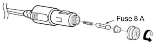
◇Fuse replacement
If the fuse blows or the transceiver stop working while using it with the optional CP-20 CIGARETTE LIGHTER CABLE, correct the source of the problem. Then replace the damaged fuse with a new rated one (FGB 8 A), as shown to the right.
INDEX
A
Accessories, supplied....1-2
AF output....11-5
Auto connect.... 11-5
Automatic Noise Limiter.... 4-2
B
Battery
Battery case 3-2
Charging....3-2
Beep level....11-7
Bluetooth 10-2
Bluetooth settings....11-4
Device search....11-4
Disconnecting....10-3
LE device....10-3
Pairing 10-2
Unpairing 10-3
D
Device initialize....11-5
E
Electromagnetic Interference.... 10-2
Emergency frequency.... 4-3
F
Firmware version 11-7
Front panel 2-2
Function display.... 2-3
G
Group 8-5
Group name....8-5
H
Headset connection....1-5
Headset settings....11-5
K
Key beep 11-7
Keypad lock....2-2
L
LCD backlight 11-7
LCD contrast.... 11-7
LCD night mode.... 11-7
M
Memory channel
Deleting 8-5
Editing 8-2
Saving a frequency....8-6
Saving a waypoint 8-6
User type 8-3
Menu screen, using 11-2
N
Noise limiting 4-2
O
One-touch PTT 11-5
Options 12-3
P
Power save....11-5
Priority channel....9-2
Priority watch....9-2
PTT beep....11-5
R
Recall channels 4-3
Receiving....4-2
S
Scan types....7-2
Specifications 12-2
Squelch.... 4-2
T
Time out timer....11-6
Transmitting 4-2
V
VOR navigation
CDI screen 5-2
Crosschecking position 5-4
OBS....5-2
W
Waypoint navigation
Flight plan, adding 6-4
Flight plan, deleting 6-5
Flight plan, editing 6-5
Flight plan, selecting....6-3
Navigation style 11-4
Selecting a waypoint 6-2
Count on us!

natural_image
Blank image with a light gray background and a black horizontal bar at the bottom (no text or symbols)- INTRODUCTION
- IMPORTANT
- Supplied accessories
- Attaching accessories
- Antenna
- CAUTION:
- ◇Battery pack/Battery case
- To attach:
- To detach:
- Attaching accessories (Continued)
- ◇Belt clip
- Headset connection
- Front, top and side panels (IC-A25C/IC-A25CE)\*
- PRIORITY CHANNEL KEY [9]/[PRIO] (p. 9-2)
- [UP]/[DOWN]/[LEFT]/[RIGHT]
- 2
- Function display
- Indicators
- BATTERY INDICATOR
- GROUP/MEMORY INDICATOR GROUP 10012
- Icons
- FUNCTION ICON F
- RX/TX ICON RX TX
- AUTOMATIC NOISE LIMITER ICON ANL. 4-2)
- VOX ICON V
- Bluetooth® ICON \*(p. 10-2)
- WX ICON (For only the IC-A25N and IC-A25C)
- TAG ICON TAG
- DUPLEX ICON D(HP 9-4)
- ◇Text area
- Battery charger
- NOTE:
- Battery case
- Receiving and transmitting
- ◇Setting the frequency
- Using dial:
- ○ Selecting a Memory channel
- ◇Receiving
- ◇Adjusting the squelch level
- ◇ Using the Automatic Noise Limiter (ANL) function
- ◇Transmitting
- Selecting the 121.5 MHz emergency frequency
- Selecting the Recall channels
- Keys used for Navigation Function
- Course Deviation Indicator (CDI) screen
- Using the Omni Bearing Selector (OBS)
- Flying to a VOR station
- Select a VOR station's frequency.
- Push [F], and then push [OBS] to enter the OBS mode.
- Push [ENT].
- Example:
- Push [F], and then push [TO FROM].
- Push [F], and then push [TO FROM] again.
- Flying to a VOR station (Continued)
- ◇Crosschecking position
- Waypoint Navigation screen 6-2
- Selecting a waypoint....6-2
- Flying through a flight plan....6-3
- Managing Flight plan....6-4
- Waypoint Navigation screen
- ◇Icon Area
- ◇Navigation Area
- WAYPOINT NAME INDICATOR ➕RJOY
- ETE INDICATOR ETE 00:01
- SOG INDICATOR SOG 100kt
- DISTANCE INDICATOR DIST2.1 nm
- RANGE INDICATOR RNG 3nm
- (For only the Normal screen)
- GPS ICON
- HEADING INDICATOR 098°
- DESTINATION ICON (For only the Normal screen)
- Selecting a waypoint
- ◇Selecting a waypoint from the memory
- ◇Selecting a waypoint from a flight plan
- Selecting a waypoint (Continued)
- ◇Selecting a waypoint near your position
- ◇Setting a waypoint manually
- ◇Selecting a waypoint from history
- Flying following a flight plan
- ◇Selecting a flight plan
- ◇Reversing a flight plan
- Managing Flight plans
- ◇Adding a flight plan
- TIP:
- Changing the waypoint order/ Deleting the added waypoint:
- Managing Flight plans (Continued)
- ◇Editing a flight plan
- ◇Deleting a flight plan
- Using the Scan function
- Push [F], and then push [SCAN] to start a scan.
- Push [CLR] to cancel the scan.
- Scan types
- ◇VFO scan
- ○ IC-A25N/IC-A25NE
- ○ IC-A25C/IC-A25CE
- ◇Memory channel scan
- ○ Normal scan
- ○ Priority scan
- Description
- Editing Memory channels
- Example: Editing a Memory channel name
- Editing memory channels (Continued)
- ◇Memory channel name
- ◇Type
- ◇Frequency
- ○ RX/TX frequency
- ○ RX frequency
- ○ TX frequency
- ○ Duplex function
- ○ Weather channel
- ◇TAG setting
- ◇Position
- ○ Latitude
- ○ Longitude
- ○ Magnetic variation
- ◇Group
- ◇Group name
- Deleting a Memory channel
- Editing the User Type
- Saving contents into the Memory channels
- ◇Saving a Waypoint
- (For only the IC-A25N and IC-A25NE)
- ◇Saving a frequency
- Priority watch
- ◇Setting the Priority channel
- ◇Using the Priority Watch function
- Using a Weather channel (For only the IC-A25N and IC-A25C)
- ◇Selecting a Weather channel
- ◇Receiving a Weather Alert
- ◇Scanning Weather channels
- ◇Weather channel tag settings
- Using the Duplex function (For only the IC-A25N and IC-A25NE)
- Turn ON the Duplex setting
- Setting the Duplex TX frequency
- ◇Using the Duplex function
- Release [PTT] to return to receive.
- Operating Bluetooth
- Bluetooth®
- Electromagnetic Interference
- Pairing with a device
- Turning ON the transceiver's Bluetooth function
- Entering the VS-3 Pairing mode
- Pairing and connecting the Bluetooth headset
- Pairing with a Low Energy device
- Disconnecting a paired device
- Unpairing a device
- Bluetooth settings
- Bluetooth module specifications
- Using the Menu screen
- Search Near ST (For only the IC-A25N and IC-A25NE)
- WPT Navigation
- WPT Navigation (Continued)
- ◇FPL Navigate
- ○ Select FPL
- ○
- ◇Add Waypoint
- ◇Manage FPL
- ○ Add FPL
- ○ Edit FPL
- ○ Delete FPL
- ◇GPS Status
- ◇GPS Info
- ◇Settings
- ○ GPS Set
- ○ Navigation Style
- ○ Auto Change
- Bluetooth
- ◇Pairing/Connect
- ○ Search Device
- ◇
- Bluetooth (Continued)
- ○ Bluetooth Set
- ○ Auto Connect
- ○ Headset Settings
- - AF Output
- - Headset Function
- - Icom Headset
- Power Save:
- One-touch PTT:
- PTT Beep:
- Device Info
- - Device Name:
- Manage Memory
- ◇Edit Memory
- ◇Delete Memory
- ○ User Type 1/User Type 2
- Radio Settings
- ◇Time Out Timer
- ◇Weather Alert
- (For only the IC-A25N and IC-A25C)
- ◇WX CH TAG Set
- ◇Duplex Set
- ◇Duplex TX Freq
- ◇VOX Set
- ◇VOX Delay
- ◇VOX Level
- ◇Priority CH
- Display Settings
- ◇Backlight
- ◇Contrast
- ◇Night Mode
- Units
- ○ Distance/Speed
- ○ Bearing
- Sounds Settings
- ◇Beep
- ◇Side Tone
- Others
- ◇Battery Status
- ◇Version
- Specifications....12-2
- Options....12-3
- SPECIFICATIONS AND OPTIONS
- Specifications (Measurements made without an antenna.)
- ◇General
- ◇Transmitter
- Specifications (Continued)
- ◇Receiver
- Options
- ◇Charger
- ◇Belt clip and belt hangers
- ◇Others
- ◇Fuse replacement
- INDEX
- A
- B
- Battery
- D
- E
- F
- G
- H
- K
- L
- M
- Memory channel
- N
- O
- P
- R
- S
- T
- V
- VOR navigation
- W
- Waypoint navigation
Brand : ICOM
Model : IC-A25C
Category : Radio