
SDX-135Z - Smoke detector Interlogix - Free user manual and instructions
Find the device manual for free SDX-135Z Interlogix in PDF.


| Brand | Interlogix |
| Model | SDX-135Z |
| Product Type | Smoke Detector |
| Dimensions | 4.1 inches diameter x 1.6 inches height |
| Weight | 0.3 lbs (with battery) |
| Power Source | 9V alkaline battery (included) |
| Sensor Type | Photoelectric |
| Alarm Volume | 85 dB at 10 feet |
| Operating Temperature | 32°F to 100°F (0°C to 38°C) |
| Humidity Range | ≤85% relative humidity (non-condensing) |
| Compliance | UL 217 listed |
| Warranty | 10 years limited |
| Mounting | Ceiling or wall mount with included bracket |
| Test/Reset Button | Yes, for weekly testing and alarm silencing |
| Low Battery Warning | Chirp every 30 seconds for up to 7 days |
| End-of-Life Alert | Chirps after 10 years of operation |
| Maintenance | Test monthly, replace battery annually, clean with vacuum brush |
| Spare Parts | 9V battery (standard replacement) |
| Repairability | Non-repairable; replace unit at end of life |
Frequently Asked Questions - SDX-135Z Interlogix
User questions about SDX-135Z Interlogix
0 question about this device. Answer the ones you know or ask your own.
Ask a new question about this device
Download the instructions for your Smoke detector in PDF format for free! Find your manual SDX-135Z - Interlogix and take your electronic device back in hand. On this page are published all the documents necessary for the use of your device. SDX-135Z by Interlogix.
USER MANUAL SDX-135Z Interlogix
Wireless Smoke Detector with Heat and Freeze Sensor User Guide

interlogix
United Technologies

SIGNALISATION SIGNALING

LISTED HOMOLOGUÉ
Attention: Please take a few minutes to thoroughly read this user guide which should be saved for future reference.
NOTE: Leave this user guide with the home owner.
You do NOT need a home wi-fi system to use these units. Multiple wireless units create their own independent wireless detector network, in addition to wireless connection with a compatible panel.
Thank you for purchasing this Interlogix smoke detector
This model is powered by a non-replaceable, long life sealed lithium battery system, and includes SMART HUSH® Control to temporarily silence nuisance alarms. It is capable of Wireless Interconnect with compatible units, and can also communicate with an appropriate panel.

READ SECTION 9: Installation / Activation / Wireless, before powering the units. You do NOT need a home wi-fi system to use these units. Multiple wireless units create their own independent wireless detector network.
Teach children how to respond to the alarm and that they should never play with the unit. Your Interlogix smoke detector was designed for use in a residential environment. It is not designed for use in a recreational vehicle (RV) or boat.
NOTE: Please thoroughly read this user guide and save the document for future reference and to pass on to any subsequent owner.
The National Fire Protection Association (NFPA) and the manufacturer recommend replacing this detector ten years from the date code on back of the detector.
Customer Service: 1-855-286-8889
Please write down the below information and have this at hand when you call.
(on back): ____
Code (on back): ____
if Purchase: ____
: Purchased: ____
Replace:
Contents
- Smoke Alarm: What To Do When The Alarm Sounds....4
- Carbon Monoxide Alarm: What To Do When The Alarm Sounds ....5
- Other Detector Visual And Audible Indicators ....6
- Troubleshooting Guide ....8
- Introduction, Product Features & Specifications....10
- Limitations Of Smoke Detectors....14
- Recommended Locations For Smoke Detectors ....15
- Locations To Avoid ....17
- Installation / Activation / Wireless ....18
9.1 Set Up A Wireless Detector Network (Wireless Interconnect) .....19
9.2 Adding Detectors to an Existing Wireless Interconnected Network ....21
9.3 Resetting a Detector's Wireless Interconnect Settings 22 - Enrolling a Detector With a Panel ....23
- Operation and Testing....24
- Recognizing Nuisance Alarms ....26
- Battery 27
- Permanently Disable Detector / Discharge Battery ....28
- Cleaning Your Detector ....29
- Good Safety Habits .... 30
- Service And Warranty 33
1. Smoke Alarm: What To Do When the Alarm Sounds
Smoke alarm pattern is three long beeps, a 1.5 second pause, and three long beeps repeating. The red LED blinks in time with alarm pattern.
- Alert small children in the home as well as anyone else that might have difficulty recognizing the importance of the alarm sounding or that might have difficulty leaving the area without help.
- Leave immediately by your escape plan. Every second counts, so don't waste time getting dressed or picking up valuables.
- In leaving, don't open any inside door without first feeling its surface. If hot, or if you see smoke seeping through cracks, don't open that door! Instead, use your alternate exit. If the inside of the door is cool, place your shoulder against it, open it slightly and be ready to slam it shut if heat and smoke rush in.
- If the escape route requires you to go through smoke, stay close to the floor where the air is cleaner. Crawl if necessary, and breathe shallowly through a cloth, wet if possible.
- Once outside, go to your selected meeting place and make sure everyone is there.
- Call the fire department from your cell phone outside, or from your neighbor's home-not from yours!
- Don't return to your home until the fire officials say that it is all right to do so.
- There are situations where a smoke alarm may not be effective to protect against fire as stated in the NFPA Standard 72. For instance:
a) smoking in bed
b) leaving children home alone
c) cleaning with flammable liquids, such as gasoline
NOTE: See Section RECOGNIZING NUISANCE ALARMS, for nuisance alarm situations.
2. Carbon Monoxide Alarm: What To Do When the Alarm Sounds
NOTE: This is not a carbon monoxide (CO) alarm, but will receive and transmit a CO alarm signal (four quick beeps repeating every 5 seconds) from an interconnected CO or combination smoke / CO alarm/detector.
Carbon monoxide (CO) alarm pattern is four quick beeps repeating every 5 seconds. The red LED blinks in time with alarm pattern.
WARNING: CARBON MONOXIDE ALARM ACTIVATION INDICATES THE PRESENCE OF CARBON MONOXIDE (CO) AT HIGH CONCENTRATIONS WHICH CAN KILL YOU.
1) Operate the Test/Hush button. NOTE: Pressing the button on the initiating alarm unit (green LED flashing every second) will silence the alarm notification, including all interconnected units. If the unit goes into alarm mode again within six minutes, it is sensing high levels of CO which can quickly become a dangerous situation.
2) Call your emergency services (Fire Department or 911).
EMERGENCY PHONE #: ____
3) Immediately move to fresh air — outdoors or by an open door / window. Do a head count to check that all persons are accounted for. Alert small children in the home as well as anyone else that might have difficulty recognizing the importance of the alarm sounding or that might have difficulty leaving the area without help. Do not re-enter the premises nor move away from the open door/window until the emergency services responders have arrived, the premises have been aired out, and your alarm remains in its normal condition.
4) After following steps 1-3, if the alarm reactivates within a 24 hour period, repeat steps 1-3 and call a qualified appliance technician to investigate sources of CO from fuel burning equipment and appliances, and to inspect for proper operation of equipment.
If problems are identified during this inspection, have the equipment serviced immediately. Note any combustion equipment not inspected by the technician and consult the manufacturer's instructions, or contact the manufacturer directly for more information about CO safety and the equipment. Make sure that motor vehicles are not, or have not been, operating in a garage attached or adjacent to the residence. Never restart the source of a CO problem until it has been corrected. Never ignore the sound of the alarm!
NOTE: See Section RECOGNIZING NUISANCE ALARMS, for nuisance alarm situations.
3. Other Detector Visual and Audible Indicators
| Operational Mode Visual Indications Audible Indications Action/Note: | |||
| Normal Operation (standby) | One GREEN LED blink every 60 seconds. | ||
| Freeze Warning One RED | LED blink every 20 seconds. | None None. Flashing continues | while condition exists. |
| Tamper Condition One RED | LED blink every 30 seconds (after a 3 minute delay). | Detector chirps once when tamper condition is first sensed, then the detector will chirp every 30 seconds after a 3 minute delay. | Reattach detector to its trim plate, otherwise flashing and chirping will continue while condition exists. |
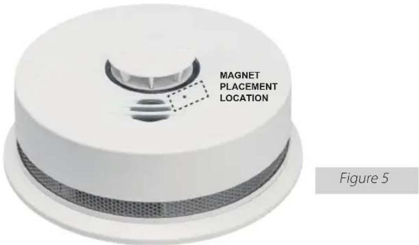
| System Test Mode Rapidly | flashing RED LED for 10 seconds duration | 1 detector chirp when magnet detected, 2 detector chirps when System Test mode enabled | Hold magnet next to button for 4 seconds. See Figure 5. |
| Local Detector Test (button press when no alarm condition is present) | Flashes RED, AMBER, GREEN, then current protocol | Temporal T3 pattern Allow completion of test or perform button press to cancel, return to normal operation | |
| Monitoring Station Signal Integrity Test (button press and hold for 4 sec when no alarm condition is present) | Flashes RED, AMBER, GREEN, then current protocol | Two chirps after button is pushed/held for approx 4 seconds, then T3 pattern. | Allow completion of the test. Confirm panel has received alarm notification, and that the monitoring station has received an alarm signal from the device. |
| System Detector Test (button press in System Test Mode when no alarm condition is present) | Flashes RED, AMBER, GREEN, then current protocol on each detector in the network | Temporal T3 pattern Allow completion of test or perform button press to cancel, return to normal operation. | |
| Smoke/Heat Alarm Memory (detector has experienced an alarm event within the last hour) | Alternating flashing RED and AMBER LEDs. 1 second RED/1 second AMBER/ 10 seconds OFF, repeating for 1 hour | None Press test button to clear alarm | memory, or allow 1 hour time out to return to normal operation.NOTE: standard test sequence will follow. (Push/release button again to cancel test). |
| Smoke Alarm Hush Mode (SMART HUSH®CONTROL) | Red LED blinks every 2 sec. | After button push: Smoke alarm pattern stops. (If there is too much smoke, smoke alarm pattern continues.) | This feature is to be used only when a known alarm condition, such as smoke from cooking, activates the alarm. |
| Locate None After button push on non-ini | - tiating unit, only initiating unit continues alarm pattern. | Use this to quickly locate the alarm source and determine if alarm is nuisance or real. | |
| Initiating Alarm Detector (multiple detectors in an interconnected system) | Green LED blinks once per sec indicating that this is the unit initiating the alarm in an interconnected, multiple detector, system. | Unit in Smoke Alarm mode. During alarm, the initiating alarm red blink will be interrupted by a green blink. | |
- Troubleshooting Guide
| Trouble Condition | Visual Indications | Audible Indications | Action: |
| Fault Mode/Fatal Error | One AMBER LED blink every 5 seconds. | Detector chirps every 30 seconds. | 1. Push the Test/Hush button once to attempt to reset the detector.The RED LED will blink out an Error Code (number of blinks) when the Test/Hush button is pushed/released once.Report the number of blinks to Customer Service, if needed.2. Clean your detector. See “Cleaning Your Detector” for instructions.3. Remove detector from service. If fatal error cannot be cleared, permanently discharge and decommission the detector. |
| Network Error (if a detector loses wireless interconnect connection due to loss of signal) | One AMBER LED blink every 5 seconds. | Detector chirps every 30 seconds. (NOTE: chirps only occur if network includes more than 2 detectors.) | Remove device from mounting bracket, and try rotating and re-installing the device in a different orientation on the mounting bracket. This might align the antenna in a better position.1. Push the Test/Hush button once to silence the audible indication for 24 hours at a time.The RED LED will blink out an Error Code (number of blinks) when the Test/Hush button is pushed/released once. Report the number of blinks to Customer Service, if needed.2. Follow instructions in “Resetting a Detector's Wireless Interconnect Settings.”, then attempt to rejoin the network by following the instructions in "Adding Detectors to an Existing Wireless Interconnected Network."*If the error persists, remove, discharge, and replace the detector as soon as possible. |
| Network Error due to loss of radio (CCI supervision) | One AMBER LED blink every 5 seconds. | Detector chirps every 30 seconds, regardless of the number of detectors in the network. | 1. Push the Test/Hush button once to silence the audible indication for 24 hours at a time.The RED LED will blink out an Error Code (4 blinks) when the Test/Hush button is pushed/ released once. Report the number of blinks to Customer Service, if needed.2. Remove, discharge, and replace the detector as soon as possible. |
| Low Battery One AMBER LED blink every 5 seconds. | Detector chirps every 60 seconds | Remove, discharge, then dispose of detector. Replace as soon as possible. | |
| End of Detector Life (EOL) | One AMBER LED blink every 5 seconds. | Double detector chirp every 30 seconds. | The RED LED will blink out an Error Code of 9 blinks. Start of EOL will be delayed if Night Detect is active. |
| Hush (for Network Error, End of Life) | One AMBER LED blink every 5 seconds. | Chirp temporarily silenced for 24 hours. | Push the Test/Hush button to initiate Hush for 24hrs. |
| Sensor CleanlinessLevel (Clean-Me Indication) | AMBER LED Clean-Me blink sequence after TESTING (PUSH TO TEST BUTTON) temporal pattern per “Operation and Testing” | None 1. Push the Test/Hush | button to initiate detector test. Following the temporal patterns, the AMBER LED will blink the cleanliness status of the detector:0-1: Unserviceable fault; remove, discharge, and replace the detector.2-3: Insensitive; requires cleaning per “Cleaning Your Detector” section.4-7: Normal Sensitivity8-9: Too sensitive, requires cleaning per “Cleaning Your Detector” section. |
| Alarm Fault: Number of RED LED Blinks (short duration blinks) | Wireless Fault: Number of RED LED Blinks (long duration blinks) |
| 7: Push to Test8: Memory9: Life Expiration10: Smoke Chamber12: Temperature Sensor Supervision14: Smoke Drift Compensation | 2: Fault Coordinator3: Fault RFD4: CCI Supervision5: RFD Check In6: RFD Time Sync |
5. Introduction, Product Features and Specifications
Introduction
The Interlogix SDX-135Z supervised photoelectric smoke detector with heat and freeze sensors is a self-diagnostic Learn Mode detector with wireless interconnection, 10-yr sealed battery and sensor life, built-in sounder, diagnostic/status LED, integrated fixed temperature and rate-of-rise heat sensor and a pre-freeze condition indicator.
The SDX-135Z uses a 319.5MHz transmitter for communication to the control panel and a 915MHz transceiver for interconnection communication between networked detectors. Up to 24 detectors can be a part of the same interconnected network. The dual transmitter design ensures interconnection integrity is maintained independent of control panel status. Because of this unique design the SDX-135Z is multi-listed to UL217, UL268, and ULC-S531 requirements.
The SDX-135Z wireless smoke detector with heat and freeze sensor is compatible with the following panels:
- Advisor One Interlogix Learn Mode panels
- Concord 4
- Simon XT
- Simon XTi
- Simon XTi-5
- NX-4
- NX-6
- NX-8
- NX-8E
- NX-8V2
- UM-5000-CPU
- ZW-6400
Note: Refer to control system / panel installation instructions for compatible panel information.
The SDX-135Z uses 10-year sealed-in lithium batteries ensuring continuous operation over the 10 year life of the detector. This eliminates worry about battery removal or unauthorized deactivation of the detector. The self-activation feature activates the detector when attached to the mounting bracket. At the end of detector life, the unit will chirp and send communication back to control panel, indicating the detector is in need of replacement (see Troubleshooting Guide).
To help identify the date to replace the detector, a label has been affixed to the side of the detector. Write the "Install date" in the space provided, and then write in the "Replace by" date (10 years from initial power up) in permanent marker on the label prior to installing the detector.
Product Features and Specifications:
Power 3V DC non-replaceable sealed lithium batteries
Smoke sensor Photoelectric
Temperature sensor NTC Thermistor
Battery life 10 years*
Detector life 10 years
Audible alarm
85dB at 10' @ 3.0 to 3.5 KHz pulsing alarm
Smoke/heat
Temporal T3 pattern
CO (transmit)
Temporal T4 pattern (received and transmitted from an interconnected CO or Combo detector)
Dimensions ∅ 5.6 ± 0.01in. × 2.3 ± 0.04in.
(∅142.3 ± 0.3mm × 59.0 ± 1.0mm)
Smoke Sensitivity 2.32 +/- 1.35 %/ft. obscuration
Product Features and Specifications:
| Rate-of-Rise (ROR) | 15°F/min (8.3C/min) monitoring above 105°F |
| heat detection | (40.5 °C) |
| Fixed temperature | ~135°F (57.2°C) |
| heat detection | |
| Freeze warning 41°F (5°C) ± 5°F (2.8°C) | |
| Storage temperature -4 °F (-20°C) to 140°F (60°C) | |
| Operating environment | |
| Temperature | 32 °F to 100 °F (0 °C to 37.8 °C) |
| Relative humidity | 0 to 95% noncondensing |
| Regulatory | UL217, UL268, CAN/ |
| Listings | ULC-S531, CSFM, FCC, IC |
*3 year warranty. Not a battery performance claim.


Product Ordering:
Model Description
SDX-135Z Wireless Interconnected Smoke Detector with Heat and Freeze
Sensor, Sounder, UL 217, UL 268, ULC-S531
Accessories
SM-200 Smoke! In A Can (canned smoke) for functional testing of smoke
detectors
6. Limitations of Smoke Detectors
⚠ WARNING: PLEASE READ CAREFULLY AND THOROUGHLY
- Life safety from fire in residential occupancies is based primarily on early notification to occupants of the need to escape, followed by the appropriate egress actions by those occupants.
- Fire warning systems for dwelling units are capable of protecting about half of the occupants in potentially fatal fires. Victims are often intimate with the fire, too old or young, or physically or mentally impaired such that they cannot escape even when warned early enough that escape should be possible. For these people, other strategies such as protection-in-place or assisted escape or rescue are necessary.
- Leading authorities recommend that both ionization and photoelectric smoke alarms be installed to help insure maximum detection of the various types of fires that can occur within the home. Ionization sensing alarms may detect invisible fire particles (associated with fast flaming fires) sooner than photoelectric alarms. Photoelectric sensing alarms may detect visible fire particles (associated with slow smoldering fires) sooner than ionization alarms.
- A battery powered alarm must have a battery of the specified type, in good condition and installed properly (This model has a sealed battery).
- Smoke alarms must be tested regularly to make sure the battery and the alarm circuits are in good operating condition.
- Smoke alarms cannot provide an alarm if smoke does not reach the alarm. Therefore, smoke alarms may not sense fires starting in chimneys, walls, on roofs, on the other side of a closed door or on a different floor.
- If the alarm is located outside the bedroom or on a different floor, it may not wake up a sound sleeper.
- The use of alcohol or drugs may also impair one's ability to hear the smoke alarm. For maximum protection, a smoke alarm should be installed in each sleeping area on every level of a home.
NOTE: This alarm is not intended to alert hearing impaired individuals.
7. Recommended Locations for Smoke Detectors
- Locate detectors in all sleeping areas. Try to monitor the exit path as the bedrooms are usually farthest from the exit. If more than one sleeping area exists, locate additional detectors in each sleeping area.
-
Locate additional detectors to monitor any stairway as stairways act like chimneys for smoke and heat.
-
Locate at least one alarm on every floor level.
- Locate an alarm in every bedroom.
- Locate a detector in every room where electrical appliances are operated (i.e. portable heaters or humidifiers), as long as the room is environmentally controlled within the temperature and humidity ranges as defined in the “Specifications” table.
- Locate a detector in every room where someone sleeps with the door closed. The closed door may prevent a detector not located in that room from waking the sleeper.
- Smoke, heat, and combustion products rise to the ceiling and spread horizontally. Mounting the smoke detector on the ceiling in the center of the room places it closest to all points in the room. Ceiling mounting is preferred in ordinary residential construction.
- When mounting a detector on the ceiling, locate it at a minimum of 4" (10 cm) from the side wall.
- When mounting the detector on the wall, use an inside wall with the top edge of the alarm at a minimum of 4" (10 cm) and a maximum of 12" (30.5 cm) below the ceiling.
- Put smoke detectors at both ends of a bedroom hallway or large room if the hallway or room is more than 30 feet (9.1m) long.
- Install smoke detectors on sloped, peaked or cathedral ceilings at or within 3ft (0.9m) of the highest point (measured horizontally).
This equipment should be installed in accordance with the National Fire Protection Association's 72 (National Fire Protection Association, Batterymarch Park, Quincy, MA 02269).
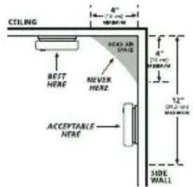

NFPA 72 states: "Smoke alarms in rooms with ceiling slopes greater than 1 ft in 8 ft (.3m in 2.4 m) horizontally shall be located on the high side of the room.
Figure 1

● Smoke Alarms for Required Protection ○ Smoke Alarms for Additional Protection △ Ionization Type Smoke Alarms with "Hush" Control or Photoelectric Type

Figure 2
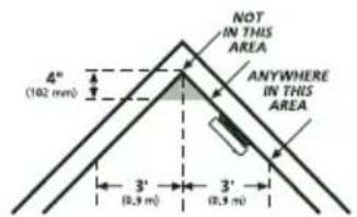

Figure 3A (US Installation)

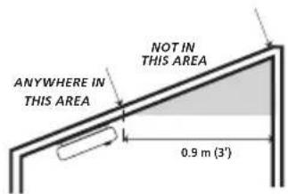
Figure 3B (Canada Installation)
8. Locations to Avoid
- In the garage. Products of combustion are present when you start your automobile.
- Normal cooking may cause nuisance alarms. If a kitchen detector is desired, it should have an alarm silence feature or be a photoelectric type.
- Do not install within 6 ft. of heating or cooking appliances.
- Less than 4" (10cm) from the peak of an "A" frame type ceiling.
- In dusty areas. Dust particles may cause nuisance alarm or failure to alarm.
- In very humid areas (above 95% RH, non-condensing). Moisture or steam can cause nuisance alarms.
• In insect-infested areas.
- In an area where the temperature may fall below 32°F (0C) or rise above 100°F (37.8C), such as garages and unfinished attics.
- Detectors should not be installed within 3 ft (.9m) of the door to a bathroom containing a tub or shower, forced air supply ducts used for heating or cooling, ceiling or whole house ventilating fans, or other high air flow areas.
- Do not install near vents, flues, chimneys or any forced/unforced air ventilation openings.
- Do not install near fans, doors, windows or areas directly exposed to the weather.
NOTE: Smoke detectors are not to be used with detector guards unless the combination (detector and detector guard) have been evaluated and found suitable for that purpose.
Smoke detectors cannot provide an alarm if smoke does not reach the detector. Therefore, smoke detectors may not sense fires starting in chimneys, walls, on roofs, on the other side of a closed door or on a different floor.
9. Installation / Activation / Wireless
You do NOT need a home wi-fi system to use these units. Multiple wireless units create their own independent wireless detector network (wireless interconnect between multiple detectors). In addition, these units can wirelessly communicate with an appropriate control panel.
WARNING: THIS DETECTOR SHOULD BE INSTALLED BY A CERTIFIED TECHNICIAN.
WARNING: FAILURE TO PROPERLY INSTALL AND ACTIVATE THIS DETECTOR WILL PREVENT PROPER OPERATION AND RESPONSE TO HAZARDS.

If you are installing detectors and will use the wireless interconnect function, proceed to section 9.1 "Set Up a Wireless Detector Network (Wireless Interconnect)" If you are not using the wireless detector-to-detector interconnect function, then proceed with the following two steps, and then skip ahead to the "ENROLLING A DETECTOR WITH A PANEL" section.
-
After selecting the proper location for the detector, attach the mounting bracket (trim plate) to the wall or ceiling. To ensure aesthetic alignment of the detector with the hallway, or wall, the "A" line on the mounting bracket (trim plate) must be parallel with the hallway when ceiling mounted or horizontal when wall mounted.
-
Install the detector fully on the mounting bracket (trim plate) by rotating the detector in a clockwise direction.
NOTE: Installing the detector on the mounting bracket (trim plate) will automatically activate the battery. The power up sequence is indicated by the LED ring slowly glowing GREEN on/off one time.
NOTE: Detectors will emit a series of slow RED LED glowing on/off as the detector searches for a wireless network. If you are intending to use the detectors without the wireless interconnect function, ignore these notifications, and the wireless interconnect function will eventually turn off (\~15 minutes) OR to immediately finish this process, push the Test/Hush button until two beeps are heard (approximately 4 seconds). The LED will change to glowing GREEN on/off every second. Repeat the button push/hold for another 4 seconds, until two beeps are heard, and then release the button. This will close the network.
- When the network has been closed, each detector's GREEN LED will change from glowing on/off every second to flashing once every 60 seconds to indicate normal operation.
NOTE: The battery activation is a one-time feature. After activation, the battery cannot be turned off, and can only be discharged at the end of unit life. If the detector is removed from the mounting plate, the battery will remain active. See Permanently Disable Detector / Discharge Battery section to de-energize the detector.
WIRELESS
These models have wireless detector interconnect capability. When one interconnected detector sounds an alarm, all other compatible wireless detectors in the wireless detector network will alarm.
A maximum of 24 compatible devices may be interconnected in a multiple station arrangement in conjunction with a compatible panel.
This detector is not designed to be interconnected with other manufacturer's products, unless otherwise specified.
WIRELESS INTERCONNECT MODEL COMPATIBILITY
The following Interlogix models can be interconnected using wireless interconnect:
- SDX-135Z, CDX-135Z
• Maximum distance between wireless interconnect models is 300 feet in open air.
9.1 Set up a Wireless Detector Network (Wireless Interconnect)
- Remove all wireless detectors from their packaging (suggest using a table and activating all detectors in a group).
- Power on all detectors by attaching the detectors onto the mounting bracket (trim plate) to activate the battery, or by carefully turning the red activation wheel with a screwdriver. See Figure 4.
- The GREEN LED will fade on and off once, then the RED LED will begin fading on/off every 3 seconds.
NOTE: If no further steps are taken within 15 minutes of initial power up, the wireless function will turn off. The detector will then perform as a single station detector.


Figure 4
- After all detectors are powered on and the RED LED is glowing on/off, push and hold the Test/Hush button on any one detector until two beeps are heard (approximately 4 seconds) and then release the button. This detector will automatically create a new wireless network.
- A brief series of quick GREEN LED blinks will occur and then the GREEN LED will fade on/off every second on the button-pushed detector (network creator).
- Wait for the other wireless detectors to join the wireless network.
- A brief series of quick GREEN LED blinks will occur and then the GREEN LED will fade on/off approximately every 3 seconds.
NOTE: At this point, you can push/release the test button once on any detector, and the RED LED will flash the number of enrolled detectors.
- Wait for the network setup to timeout (approximately 15 minutes), OR to immediately close the network, push the Test/Hush button until two beeps are heard (approximately 4 seconds) and then release the button. The network can be closed from any device enrolled in the network.
- When the network has been closed, each detector's GREEN LED will change from glowing on/off every second to flashing once every 60 seconds to indicate normal operation.
- After selecting the proper location for your detector, attach the mounting bracket to the wall or ceiling. To ensure aesthetic alignment of the detector with the hallway, or wall, the "A" line on the mounting bracket must be parallel with the hallway when ceiling mounted or horizontal when wall mounted.
- Install the detector fully on the mounting bracket (trim plate) by rotating the detector in a clockwise direction. NOTE: The detector will mount to the bracket in 4 positions (every 90 degrees).
- The detector is now activated. After installation / activation, test your detector as described in Operation and Testing section.
9.2 Adding Detectors to an Existing Wireless Interconnected Network
For various reasons, you might want to add additional detectors to your existing wireless interconnection network.
- Remove the new detector from its packaging.
- Choose one existing, installed detector (not the new detector). Place and hold a magnet for four seconds on the cover of the existing detector in the network at the designated location per Figure 5. The detector will beep once when the magnet is detected, then the detector will beep twice and will start flashing the RED LED rapidly to indicate the detector is in System Test Mode.
- Push and hold the test button on the same detector (in System Test Mode) until two beeps are heard (approximately 4 seconds), and then release the button.
- The button-pushed detector will cause the GREEN LED to fade on/off on each detector in the existing network to signal that the wireless interconnection network has been opened.
NOTE: From this point, you have fifteen (15) minutes to power up the new detector.
-
Power up the new wireless detector by twisting the detector onto the mounting bracket (trim plate) to activate the battery, or by carefully turning the red activation wheel with a screwdriver. See Figure 4.
-
After initial GREEN LED on/off sequence, the new detector's RED LED will fade on/off every 3 seconds as it searches for the network.
-
A fast GREEN LED flickering, followed by a slow GREEN LED fading on/off confirms the new detector has found and joined the existing wireless interconnection network.
-
Wait fifteen (15) minutes for the network setup to timeout, OR to immediately close the network, push and hold the test button on any device enrolled in the network until two beeps are heard (approximately 4 seconds), and then release the button.
- GREEN LED flashes once every 60 seconds on the new detector to indicate normal operation.
- After selecting the proper location for your detector, attach the mounting bracket to the wall or ceiling. To ensure aesthetic alignment of the detector with the hallway, or wall, the "A" line on the mounting bracket must be parallel with the hallway when ceiling mounted or horizontal when wall mounted.
• Install the detector fully on the mounting bracket (trim plate) by rotating the detector in a clockwise direction. NOTE: The detector will mount to the bracket in four positions (every 90 degrees).
- The detector is now activated. After installation / activation, test your detector as described in Operation and Testing section.
9.3 Resetting a Detector's Wireless Interconnect Settings
If you experience a delay or problem during wireless interconnection setup, you might need to start over as if the detector is first removed from its packaging. Also, this "out-of-box" mode can be used to attempt to reset/clear a network error condition.
NOTE: The magnetic switch is disabled when network is open and GREEN LED is glowing on/off. The magnetic switch is also disabled when the detector is in "out-of-box" mode and has not been enrolled in the network. Press and hold Test/Hush button for 4 seconds to close network before attempting to reset device to the "out-of-box" mode.
- Place and hold a magnet for 4 seconds on the cover at the designated location per Figure 5. The detector will chirp once when the magnet is detected, then the detector will chirp twice and the button will start flashing the RED LED rapidly to indicate System Test Mode has been entered.
- Press and hold the Test/Hush button for approximately 8 seconds while the RED LED is rapidly flashing. After 4 seconds, two beeps will occur (do not release the button). After 8 seconds, three beeps will occur. The button can now be released.
- Observe two cycles of RED LED on/off, one cycle of GREEN LED on/off
- The RED LED will begin fading on/off every 3 seconds.
- If no further steps are taken within 15 minutes of resetting the detector to "Out-of-Box" mode, the interconnect function will turn off. The detector will then perform as a single station detector.
10. Enrolling A Detector With A Panel
The following section provides a general guideline for programming (enrolling) the detector into control panel memory. Refer to the panel documentation for complete programming details. This model requires enrolling with a panel as two (2) separate devices.
- Set the control panel to the installer programming mode
- When requested to broadcast a signal from the detector to the panel, remove the detector from the mounting bracket (trim plate). A tamper message will be transmitted for smoke and freeze devices.
- After waiting approximately 1 minute, reinstall the detector on the mounting bracket (trim plate). The detector will start chirping once every 30 seconds if not re-installed on the trim plate after 3 minutes.
- Exit installer programming mode on the panel.
NOTE: Each enrollment type (smoke, Freeze) is programmed with a unique TX ID when manufactured. Labels included on the outside and inside of the packaging provide these IDs. The unique ID is enrolled into the control panel at the time of installation. Use these IDs where appropriate in the specific panel being used enrollment instructions.
Verify programming and detector-to-panel communication
Before mounting, verify that the desired detector location provides good RF communication to the panel.
To Verify Programming And RF Communication
- Put the panel into Dealer Sensor Test mode (refer to the specific panel installation instructions)
- Take the detector to the desired mounting location.
- Press and release the Test button. A quick beep will confirm the button has been pushed.
- Listen for the appropriate response from system sirens to determine signal integrity from the detector to the panel (refer to the specific panel installation instructions)
- Exit from Dealer Sensor Test mode.
11. Operation and Testing
Operation
The detector is operating once it is activated and testing is complete. When products of combustion (smoke) are sensed, the detector sounds a loud 85dB alarm. See Sections 1 and 2 for alarm signal descriptions.
Testing (Push To Test Button)
Test your detector weekly by pressing and releasing the test button quickly. A quick beep will confirm the button has been pushed.
See Other Detector Visual and Audible Indicators table. The alarm will sound if the electronic circuitry, horn, and battery are working. If the alarm does not sound, the detector must be replaced. Erratic or low volume sound (or no sound) coming from your detector may indicate a defective detector and it should be returned for service. See Permanently Disable Detector / Discharge Battery section to determine how to prepare the unit for shipment or disposal.
To test all detectors connected in the same network start System Test mode by placing a magnet in the location shown in Figure 5 and holding it for four seconds until the detector chirps twice and the RED LED begins blinking rapidly, and then press and release the Test/Hush button. All detectors will perform a self-test and will report their status to the panel.
Central Station Alarm Test
To force an alarm report to the monitoring station, press and hold the test button for 4 seconds until two chirps are heard. The detector will perform self test as described in Testing (push to test Button) above and will report the alarm to the monitoring station (through the panel). Verify with monitoring station that alarm was received successfully.
⚠ WARNING: Due to the loudness (85+ decibels) of the alarm, always stand about 2.5 ft (0.7M) away from the detector or use ear protection when testing.
WARNING: DO NOT use an open flame to test your DETECTOR. You could damage the DETECTOR or ignite combustible materials and start a structure fire.
Functional Smoke Test
The smoke test verifies that the detector activates when detecting smoke, that all interconnected devices also alarm, that the transmitted signal is received by the receiver/panel, and that the panel reports the alarm to the central monitoring station. The smoke test should be performed annually. A canned smoke testing agent must be used for the functional smoke test
NOTE: Use Interlogix brand of Smoke! In A Can part number SM-200.
- Wait at least 90 seconds after installation to test the smoke detector.
- Make sure the GREEN LED is flashing for normal operation (one GREEN LED blink every 60 seconds).
- From a distance of 2 - 4 feet (0.6 - 1.2m), aim spray for 1 - 2 seconds at the side (bug screen) of the detector.
-
The alarm will sound within 1 - 10 seconds if the detector functions properly.
-
Press the Test/Hush button to quiet the sounder. NOTE: Due to the high smoke concentration from the canned smoke spray, it is possible that the detector will not silence after a button push.
-
Contact the central monitoring station to verify they received the alarm report.
-
Alert the central monitoring station when you are finished testing.
NOTE: An alternative method for performing a functional smoke test in the field is to hold a smoldering punk or cotton wick close to the detector and direct the smoke into the vent openings until an alarm is indicated.
AMBIENT LIGHT SENSING
This detector samples the ambient light conditions of its location and, if possible, determines a Night/Day cycle. A valid Night/Day cycle will delay detector chirps during the night until the next Day cycle begins.
When chirping begins during the next Day cycle, you can temporarily silence End of Detector Life or Network Error chirps by pressing the Test/Hush button. Low Battery chirps cannot be silenced.
If a valid Night / Day cycle has not been established because the detector is located in either a constantly dark or lighted location, the chirps mentioned above will not be delayed at night. Moving the detector to a different location might allow the detector to determine a valid Night / Day cycle.
WARNING: REPLACE DETECTOR AS SOON AS POSSIBLE WHEN IN END OF DETECTOR LIFE OR LOW BATTERY MODE.
12. Recognizing Nuisance Alarms
SMART HUSH ® Control and Locate Feature
Smoke Nuisance
HUSH®
If you know why the alarm is sounding, and you can verify that it is not a life threatening situation, you can push the button on the initiating detector (green LED flashing every second, interrupted by T3 RED LED alarm pattern) to silence the alarm for 8-10 minutes. If the smoke is not too dense, that detector, and all interconnected detectors will silence. After the HUSH ® period, the smoke detector will automatically reset and sound the alarm if particles of combustion are still present. You can use HUSH ® repeatedly until the air has been cleared of the condition causing the alarm.
NOTE : Dense smoke will override HUSH ® and sound a continuous alarm. If no fire is present, check to see if one of the reasons listed in “Locations to avoid” may have caused the alarm. If a fire is discovered, get out of the building and call the fire department.
This detector is designed to minimize nuisance alarms. Cigarette smoke will not normally cause the detector to alarm, unless the smoke is blown directly into the detector. Combustion particles from cooking may set off the alarm if it is located too close to a cooking appliance. Large quantities of combustible particles are generated from spills or when broiling. Using the fan on a range hood which vents to the outside (non-recirculating type) will also help prevent nuisance alarms from occurring by removing these combustible products from the kitchen.
Locate
In an interconnected system (all detectors will be alarming together), a detector that detects smoke or CO and initiates an alarm is called the “initiating alarm detector.” Initiating alarm detectors will be flashing the Green LED every second during alarm (interrupted by the T3 RED LED alarm pattern). Depending on detector locations, and the location of the source of smoke or CO, it is possible to have more than one initiating detector. If you suspect a nuisance alarm situation, you can use LOCATE feature to help you locate the initiating alarm detector(s) in a wireless alarm interconnect system. Push the button on any non-initiating wireless detector, and ALL wireless detectors EXCEPT the initiating alarm detector(s) will silence for two minutes. You can use the LOCATE feature repeatedly until you find the initiating alarm detector(s), or the air has been cleared of the condition causing the alarm.
NOTE: HUSH ® and Locate features are dependent on the type of models enrolled in the wireless interconnect system. Non-wireless models cannot be enrolled in the wireless interconnect system and therefore cannot receive the wireless Locate feature; they will continue to alarm until the initiating detector is Hushed or the Smoke/CO condition clears.
WARNING: THIS UNIT DOES NOT DETECT CO, BUT IT WILL TRANSMIT A CO ALARM SIGNAL FROM AN INTERCONNECTED CO OR SMOKE /CO COMBINATION DETECTOR. The LOCATE feature can be used for CO alarm events also, but it is impossible to determine the source of a CO alarm using sight or smell. Always consider a CO alarm event as dangerous.
13. Battery
NOTE: This detector is powered by non-replaceable, sealed lithium batteries. No battery installation or replacement is necessary for the life of the detector.
NOTE: Constant exposure to high or low humidity or temperatures may reduce battery life.
WARNING: DO NOT ATTEMPT TO OPEN THE DETECTOR FOR ANY REASON! Do not try to repair the DETECTOR yourself. No serviceable parts included.
CAUTION: THE BATTERY USED IN THIS DEVICE MAY PRESENT A FIRE OR CHEMICAL BURN HAZARD IF MISTREATED. DO NOT RECHARGE, DISASSEMBLE, HEAT ABOVE 100°C (212°F) OR DISPOSE OF IN FIRE.
Low battery
This detector is equipped with a low battery monitor circuit. If the battery capacity can no longer provide adequate power for all alarm functions, the low battery condition will occur. See Troubleshooting Guide.
The detector battery must be discharged and the detector must be replaced within 7 days of the first occurrence of the "Low Battery Warning" to provide continuous detector protection. Reference the "Permanently Disable Detector / Discharge Battery" section below for battery discharging instructions.
14. Permanently Disable Detector / Discharge Battery
WARNING: Discharging the detector battery is PERMANENT. Once the detector battery has been placed in discharge mode, it cannot be reactivated!
• Once discharged, the detector will NO LONGER DETECT SMOKE.
- Once the detector battery is discharged, the battery is depleted and the DETECTOR will no longer function.
- Once the detector battery has been discharged, the detector cannot be mounted onto the mounting plate or reactivated.
WARNING: Failure to discharge detector battery as instructed prior to disposal may create potential for lithium battery related fire or hazard.
CAUTION: Do not disassemble and do not dispose of in fire.

To Permanently Disable Detector / Discharge Battery:
- Rotate the detector counterclockwise to remove it from the mounting plate.
- Push in the dashed area with a screwdriver to break tab.(Figure 6)
- After the tab is broken, use the screwdriver to turn the red slotted arrow to the "Permanently Disable Detector / Discharge Battery" location. This will disable the detector, stop the low battery or end of unit life "chirps" and render the detector safe for disposal by draining the battery (Figure 7).

Figures 6 (top) and 7 (bottom)
15. Cleaning Your Detector
YOUR DETECTOR SHOULD BE CLEANED AT LEAST ONCE A YEAR
You can clean the detector by using a vacuum cleaner hose and vacuuming through the openings around the perimeter of the detector. The outside of the detector can be wiped with a damp cloth. Use only water to dampen the cloth, use of detergents or cleaners could damage the detector.
If the detector is in fault mode and the AMBER LED is blinking a fault code of 2, 3, 8, or 9 flashes (after a Test/Hush button push and the temporal test sequence), the detector may be in need of cleaning. After cleaning, press the Test/Hush button. If the fault does not clear, the detector needs to be replaced. The clean-me signal will also be sent to the panel when the sensitivity level becomes too high.
- Never use detergent or other solvents to clean the detector.
- Avoid spraying air freshener, hair spray, or other aerosols near the detector.
- Do not paint the detector. Paint will seal the vents and interfere with the sensor's ability to detect smoke.
- Never attempt to disassemble the detector to clean inside. This action will void your warranty.
Storing the detector in a plastic bag during any of the above projects will protect the sensors from damage. When household cleaning supplies or similar contaminates are used, the area must be well ventilated.

WARNING: Reinstall the DETECTOR as soon as possible to assure continuous protection.
16. Good Safety Habits
Develop and Practice a Plan of Escape
Practice the following steps to prepare you and your family in the event of a fire:
- Perform fire drills regularly. Use them to assure recognition of an alarm signal.
- Draw a floor plan and show two exits from each room. It is important that children be instructed carefully, because they tend to hide in times of crisis.
- Establish one meeting place outside the home. Insist that everyone meet there during an alarm. This will eliminate the tragedy of someone reentering the house for a missing member who is actually safe.
- If you have children or physically challenged people residing in your household, use window decals to help emergency personnel identify the sleeping quarters of these individuals.
Current studies have shown smoke alarms may not awaken all sleeping individuals, and that it is the responsibility of individuals in the household that are capable of assisting others to provide assistance to those who may not be awakened by the alarm sound,, or to those who may be incapable of safely evacuating the area unassisted.
Install and maintain fire extinguishers on every level of the home and in the kitchen, basement and garage. Know how to use a fire extinguisher prior to an emergency.
Fire warning systems for dwelling units are capable of protecting about half of the occupants in potentially fatal fires. Victims are often intimate with the fire, too old or young, or physically or mentally impaired such that they cannot escape even when warned early enough that escape should be possible. For these people, other strategies such as protection-in-place or assisted escape or rescue are necessary.
Fire Prevention
Never smoke in bed, or leave cooking food unattended. Teach children never to play with matches or lighters! Train everyone in the home to recognize the smoke alarm pattern and to leave the home using their escape plan when it's heard. Know how to do "Stop, Drop and Roll" if clothes catch on fire, and how to crawl low under smoke. Install and maintain fire extinguishers on every level of the home and in the kitchen, basement and garage.NFPA (National Fire Protection Association)
Fire Safety in the Home: NFPA 72 is intended to provide reasonable safety for persons in family living units. Reasonable fire safety can be produced through the following three-point program: (1) Minimizing fire hazards (2) Providing fire-warning equipment (3) Having and practicing an escape plan.
The National Fire Protection Association's Standard 72, reads as follows:
Where required by other governing laws, codes, or standards for a specific type of occupancy, approved single and multiple-station smoke alarms shall be installed as follows:
(1) In all sleeping rooms and guest rooms
(2) Outside of each separate dwelling unit sleeping area, within 21 ft (6.4 m) of any door to a sleeping room, with the distance measured along a path of travel
(3) On every level of a dwelling unit, including basements
(4) On every level of a residential board and care occupancy (small facility), including basements and excluding crawl spaces and unfinished attics
(5) In the living area(s) of a guest suite
(6) In the living area(s) of a residential board and care occupancy (small facility)
SMOKE DETECTION – ARE MORE SMOKE DETECTORS DESIREABLE?
The required number of smoke detectors might not provide reliable early warning protection for those areas separated by a door from the areas protected by the required smoke alarms. For this reason, it is recommended that the householder consider the use of additional smoke detectors for those areas for increased protection. The additional areas include the basement, bedrooms, dining room, furnace room, utility room, and hallways not protected by the required smoke detectors. The installation of smoke detectors in attics (finished or unfinished), garages, or within 6' of a heating or cooking appliance is not normally recommended, as these locations occasionally experience conditions that can result in improper operation.
CALIFORNIA STATE FIRE MARSHALL
Early warning fire detection is best achieved by the installation of fire detection equipment in all rooms and areas of the household as follows: A smoke detector installed in each separate sleeping area (in the vicinity, but outside the bedrooms), heat or smoke detectors in the living rooms, dining rooms, bedrooms, kitchens, hallways, attics, furnace rooms, closets, utility and storage rooms, basements and attached garages.
FCC
FCC ID: SAK25609702
IC: 7145A-25609702
This device complies with FCC Part 15 and Industry Canada license exempt RSS standard(s). Operation is subject to the following two conditions: (1) this device may not cause interference, and (2) this device must accept any interference, including interference that may cause undesired operation of the device.
All transmitters regulated by IC must comply with RF exposure requirements listed in RSS-102 - Radio Frequency (RF) Exposure Compliance of Radiocommunication Apparatus (All Frequency Bands). Currently this device is approved for use for when 20cm can be maintained between the antenna and users. Specific Absorption Rate (SAR) evaluation is required if the separation distance between the user and/or bystander and the antenna and/or radiating element of the device is less than or equal to 20 cm. Exceptions are listed in RSS-102. Note that integration < 20 cm will require further certification with IC such as a Multiple listing and Class IV Permissive Change application.
If this equipment does cause harmful interference to radio or television reception, the user is encouraged to try to correct the interference by one or more of the following measures:
- Reorient or relocate the receiving antenna.
- Increase the separation between the equipment and receiver.
- Connect the equipment into an outlet on a circuit different from that to which the receiver is connected.
- Consult the dealer or an experienced radio/TV technician for help.
Changes or modifications not expressly approved by UTC Fire and Security could void the user's authority to operate the equipment.
WARNING: ANY CHANGES OR MODIFICATIONS MADE TO THIS PRODUCT NOT EXPRESSLY AUTHORIZED BY THE MANUFACTURER COULD VOID THE USER'S RIGHT TO OPERATE THIS DEVICE.
17. Service and Warranty
CONTACT INFORMATION
For contact information, visit us online at www.interlogix.com.
For technical support, see www.interlogix.com/support, or call 1-855-286-8889.
COPYRIGHT
Copyright © 2017 United Technologies Corporation. All rights reserved.
TRADEMARKS
Interlogix is a registered trademark of United Technologies Corporation. Interlogix is part
of UTC Climate, Controls & Security, a unit of United Technologies Corporation.
PLACED ON THE MARKET BY:
UTC Fire & Security Americas Corporation, Inc.
3211 Progress Drive, Lincolnton, NC, 28092, USA
Made in China
MANUFACTURER HEREBY DISCLAIMS ALL WARRANTIES AND REPRESENTATIONS, WHETHER EXPRESS, IMPLIED, STATUTORY OR OTHERWISE INCLUDING (BUT NOT LIMITED TO) ANY WARRANTIES OF MERCHANTABILITY OR FITNESS FOR A PARTICULAR PURPOSE WITH RESPECT TO THESE PRODUCTS AND ANY RELATED SOFTWARE. MANUFACTURER
FURTHER DISCLAIMS ANY OTHER IMPLIED WARRANTY UNDER THE UNIFORM COMPUTER INFORMATION TRANSACTIONS ACT OR SIMILAR LAW AS ENACTED BY ANY STATE.
(USA only) SOME STATES DO NOT ALLOW THE EXCLUSION OF IMPLIED WARRANTIES, SO THE ABOVE EXCLUSION MAY NOT APPLY TO YOU. THIS WARRANTY GIVES YOU SPECIFIC LEGAL RIGHTS AND YOU MAY ALSO HAVE OTHER LEGAL RIGHTS THAT VARY FROM STATE TO STATE. MANUFACTURER MAKES NO REPRESENTATION, WARRANTY, COVENANT OR PROMISE THAT ITS ALARM PRODUCTS AND/OR RELATED SOFTWARE (I) WILL NOT BE HACKED, COMPROMISED AND/OR CIRCUMVENTED; (II) WILL PREVENT, OR PROVIDE ADEQUATE WARNING OR PROTECTION FROM, BREAK-INS, BURGLARY, ROBBERY, FIRE; OR (III) WILL WORK PROPERLY IN ALL ENVIRONMENTS AND APPLICATIONS.

- INTERLOGIX
- THANK YOU FOR PURCHASING THIS INTERLOGIX SMOKE DETECTOR
- CONTENTS
- SMOKE ALARM: WHAT TO DO WHEN THE ALARM SOUNDS
- CARBON MONOXIDE ALARM: WHAT TO DO WHEN THE ALARM SOUNDS
- WARNING: CARBON MONOXIDE ALARM ACTIVATION INDICATES THE PRESENCE OF CARBON MONOXIDE (CO) AT HIGH CONCENTRATIONS WHICH CAN KILL YOU
- OTHER DETECTOR VISUAL AND AUDIBLE INDICATORS
- INTRODUCTION, PRODUCT FEATURES AND SPECIFICATIONS
- INTRODUCTION
- PRODUCT FEATURES AND SPECIFICATIONS
- PRODUCT ORDERING
- MODEL DESCRIPTION
- ACCESSORIES
- LIMITATIONS OF SMOKE DETECTORS
- ⚠ WARNING: PLEASE READ CAREFULLY AND THOROUGHLY
- RECOMMENDED LOCATIONS FOR SMOKE DETECTORS
- LOCATIONS TO AVOID
- INSTALLATION / ACTIVATION / WIRELESS
- WIRELESS
- WIRELESS INTERCONNECT MODEL COMPATIBILITY
- 9.1 SET UP A WIRELESS DETECTOR NETWORK (WIRELESS INTERCONNECT)
- 9.2 ADDING DETECTORS TO AN EXISTING WIRELESS INTERCONNECTED NETWORK
- 9.3 RESETTING A DETECTOR'S WIRELESS INTERCONNECT SETTINGS
- ENROLLING A DETECTOR WITH A PANEL
- VERIFY PROGRAMMING AND DETECTOR-TO-PANEL COMMUNICATION
- TO VERIFY PROGRAMMING AND RF COMMUNICATION
- OPERATION AND TESTING
- OPERATION
- TESTING (PUSH TO TEST BUTTON)
- CENTRAL STATION ALARM TEST
- FUNCTIONAL SMOKE TEST
- AMBIENT LIGHT SENSING
- RECOGNIZING NUISANCE ALARMS
- LOCATE
- BATTERY
- LOW BATTERY
- PERMANENTLY DISABLE DETECTOR / DISCHARGE BATTERY
- TO PERMANENTLY DISABLE DETECTOR / DISCHARGE BATTERY
- CLEANING YOUR DETECTOR
- YOUR DETECTOR SHOULD BE CLEANED AT LEAST ONCE A YEAR
- GOOD SAFETY HABITS
- DEVELOP AND PRACTICE A PLAN OF ESCAPE
- FIRE PREVENTION
- SMOKE DETECTION – ARE MORE SMOKE DETECTORS DESIREABLE
- CALIFORNIA STATE FIRE MARSHALL
- SERVICE AND WARRANTY
- COPYRIGHT
- TRADEMARKS
- PLACED ON THE MARKET BY
Brand : Interlogix
Model : SDX-135Z
Category : Smoke detector