
ZC-1 - Controller DBX - Free user manual and instructions
Find the device manual for free ZC-1 DBX in PDF.


| Product Type | Zone Controller (Wall-Mounted) |
| Model | ZC-1 |
| Brand | DBX Professional Products |
| Series | ZC Series (DriveRack/ZonePRO) |
| Compatible Units | DriveRack 220J, 260, ZonePRO |
| Zone Control | Single zone (expandable with multiple controllers) |
| Switch Inputs | 4 switch inputs (configurable via DIP switches) |
| Connections | (2) RJ45 connectors |
| Cable Type | CAT5 or CAT5E with <28.6 Ohm/1000 ft DCR, rated VW-1 or higher |
| Maximum Cable Length (Series) | 600 ft (up to 3 controllers), 300 ft (up to 6 controllers) |
| Maximum Cable Length (Parallel) | 1000 ft per run when using ZC-BOB |
| Power Supply | Powered via RJ45 from host device |
| Safety Certifications | UL 6500, IEC 60065, EN 55013 |
| Dimensions (Approx.) | 4.5 x 4.5 x 2 in (114 x 114 x 51 mm) |
| Weight (Approx.) | 0.5 lb (0.23 kg) |
| Mounting | Wall-mount (single gang) |
| DIP Switch Configuration | For setting unique zone ID (up to 16 addresses) |
| Wiring Topology | Series or parallel |
| Included Accessories | None (cables sold separately) |
| Maintenance | Clean with dry cloth; no user-serviceable parts |
Frequently Asked Questions - ZC-1 DBX
User questions about ZC-1 DBX
0 question about this device. Answer the ones you know or ask your own.
Ask a new question about this device
Download the instructions for your Controller in PDF format for free! Find your manual ZC-1 - DBX and take your electronic device back in hand. On this page are published all the documents necessary for the use of your device. ZC-1 by DBX.
USER MANUAL ZC-1 DBX
PROFESSIONAL PRODUCTS
DriveRack®/ZonePRO™
ZC Series Wall-Mounted Zone Controllers
ZC Series
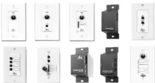
ZC-1-4 ZC-6-9 ZC-Fire ZC-BOB
User Guide
DECLARATION OF CONFORMITY
Manufacturer's Name: dbx Professional Products
Manufacturer's Address: 8760 S. Sandy Parkway
Sandy, Utah 84070, USA
declares that the product:
Product name: dbx Zone Controllers Models: ZCI, 2, 3, 4, 6, 7.
8, 9, FIRE and BOB Note: Product name may be suffixed by the letters -EU.
Product option: none
conforms to the following Product Specifications:
Safety: IEC 60065-98
EMC: EN 55013 (1990)
EN 55020 (1991)
Supplementary Information:
The product herewith complies with the requirements of the Low Voltage Directive 73/23/EEC and the EMC Directive 89/336/EEC as amended by Directive 93/68/EEC.
Vice-President of Engineering
8760 S. Sandy Parkway
Sandy, Utah 84070, USA
Date: February 3, 2003
Revised: September 10, 2004
European Contact: Your local dbx Sales and Service Office or
Harman Music Group
8760 South Sandy Parkway
Sandy, Oran 84070 USA
Ph: (801) 566-8800
Fax: (801) 56B-75B3

The symbol shown above is an internationally accepted symbol that warn of potential hazards with electrical products. The exclamation point in an equilateral triangle indicates that it is necessary for the user to refer to the owner's manual.
ZC-Remote Control Wall Controllers
USER GUIDE
Zone Controller Wiring
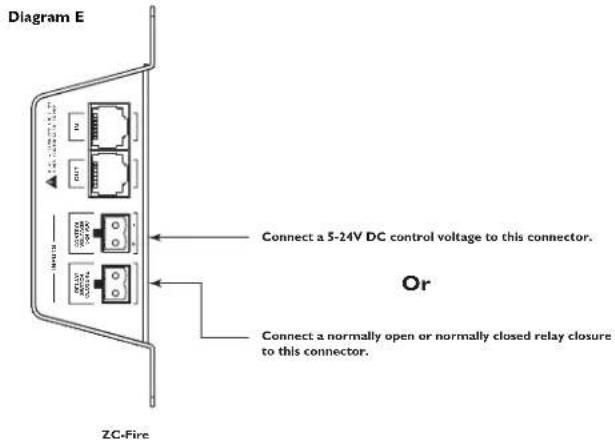
The Zone Controllers (ZC-1, ZC-2, ZC-3, ZC-4, ZC-6, ZC-7, ZC-8, ZC-9, and ZC-Fire) can be wired serially or in parallel. To wire in series each Zone Controller must have an identification or zone number chosen using the DIP switches on the side of the controller (see diagram A). Each controller must have a unique number chosen although there may be multiple Zone Controllers controlling a single zone, or a single Zone Controller that controls multiple outputs. The Zone Controllers can be tied together and connected to the DriveBack 220J, 260 or ZonePRO units (see diagram B).
The Zone Controllers may also be wired in parallel with the use of the 7C-BOB. To wire in parallel (bone not calbing), each controller must have a unique identification or member chosen using the DIP switches on the rear of the panel (see diagram A). To write in parallel, each controller must be wired into a port of the 7C-BOB with a connecting wire going to the Driverack or ZonePro (see diagram C). Diagram D shows the typical wiring for 7C-1 farnblock connections in which the installer needs to use SPDT (single pole, double-flaw) switches with one side being connected to 5 volts (+VRE) and the other side to ground (GND). Diagram E shows the proper way to interface: the 7C func to the first alarm system. Use only the relay switch closure or the 5-24V DC inputs. Do not use both inputs at the same time. For information regarding ZC setup, please see the respective manual for the Driverack or ZonePro unit that you are setting up.
Diagram A

natural_image
Technical diagram of a device rear panel and internal components (no text or symbols)Diagram B


PROFESSIONAL PRODUCTS
DriveRack®/ZonePRO® User Manual
Diagram C

flowchart
graph TD
    A["ID # 3"] --> D["dbx-branded device"]
    B["ID # 6"] --> D
    C[" "] --> D
    D --> E["USB Interface"]
Diagram D

ZC-4 Binary App notes
SW4 SW3 SW2 SW1 Hex Setting
| 0 | 0 | 0 | 0 | 0 |
| 0 | 0 | 0 | 1 | 1 |
| 0 | 0 | 1 | 0 | 2 |
| 0 | 0 | 1 | 1 | 3 |
| 0 | 1 | 0 | 0 | 4 |
| 0 | 1 | 0 | 1 | 5 |
| 0 | 1 | 1 | 0 | 6 |
| 0 | 1 | 1 | 1 | 7 |
| 1 | 0 | 0 | 0 | 8 |
| 1 | 0 | 0 | 1 | 9 |
| 1 | 0 | 1 | 0 | A |
| 1 | 0 | 1 | 1 | B |
| 1 | 1 | 0 | 0 | C |
| 1 | 1 | 0 | 1 | D |
| 1 | 1 | 1 | 0 | E |
| 1 | 1 | 1 | 1 | F |
Switches SWI-SW4 correspond to switch inputs 1-4 on the ZC's EuroBlock connector. Each switch connected to the ZC1 must be a Dual Pole Single Throw (DPST). One pole of each switch should be connected to the ground reference on the ZC's EuroBlock connector while the other pole should be connected to the +V reference. Because there are four switch inputs, there are 16 possible switch combinations. In the chart above, a "0" corresponds to a switch connected to +V reference, while a "+V" corresponds to the switch facing connected to ground. None of the poles should be left hanging but should either be connected to +V or ground.
ZC-Remote Control Wall Controllers
USER GUIDE
Zone Controller Maximum Cable Length
Note - The following cable lengths were achieved using Cat5 Enhanced cable exhibiting a maximum D.C. resistance of 29 Ohms per 1,000 feet. When connecting Zone Controllers in series, the following cable length restrictions apply:
- As shown in Diagram 1, any (3) Zone Controllers may be wired in series as long as the total cable length does not exceed 600 feet.
- Any (6) Zone Controllers may be wired in series as long as the total cable length does not exceed 300 feet. Refer to Diagram G.
- Cable runs of up to 1,000 feet may be achieved using "Home Run" wiring. An example of this is shown in Diagram II. A lixx Zone Controller Break Out Box (cllx 7C.80BJ) is used to parallel several cable runs. It should be noted that a 1,000 foot cable with a single Zone Controller may be connected directly to the DriveBack or ZonePro.
Diagram F

Diagram G

Diagram H

Cable Spec: Cat5 Cable - 4-Twisted Pairs of 24AWG wire
| RJ-45(8-Position) | RJ-45(8-Position) | |
| 1 | White/Orange | 1 -VREF |
| 2 | Orange | 2 -Zone 1 |
| 3 | White/Green | 3 -Zone 2 |
| 4 | Green | 4 -Zone 3 |
| 5 | White/Blue | 5 -Zone 4 |
| 6 | Blue | 6 -Zone 5 |
| 7 | White/Brown | 7 -Zone 6 |
| 8 | Brown | 8 -GND |
Zone Controller Compatibility Chart
| 1 | x | x | x | |
| 2 | x | x | x | x |
| 3 | x | x | x | x |
| 4 | x | x | x | x |
| FIRE | x | x | ||
| 6 | x | x | ||
| 7 | x | x | ||
| 8 | x | x | ||
| 9 | x | |||
| BOB | x | x | x | x |
ZC-Remote Control Wall Controllers
USER GUIDE
Safety Warning:
The installation of the Zone Controllers MUST be accomplished with the use of cable which is rated VW-1 or higher. Common NEG designations which meet this rating include: CMP, CMR, CMG, CM and CMX.
Specifications:
Connections:
ZC.1, ZC.2, ZC.3, ZC.6, ZC.7, ZC.8 and ZC.9 Connections: (2) RJ 45
ZC-4 Connectors: (2) RJ-45, (1) 6-pin Placris
ZC BOR Connectors: (7) RJ-45
ZC-Fire Connectors (2) RJ-45, (2) 2-Pin Phoenix
Wring
Maximum Cable Length depends on number of Zone Controllers and wiring schematic.
Series Wiring:
Maximum Cable Length varies with number of Zone Controllers. For Example, Three Zone Controllers: 600 ft. Six Zone Controllers: 300 ft.
Parallel Wiring:
Using a ZC-ROB:Up to Six Zone Controllers: 1000 ft. Cable: CAT5 or CAT5E with <28.6 Ohm/M (Ohm/1000 ft.) nominal DCR and rated VW-1 or higher
Safety Agency Approvals:
LL 6500, IEC 60065, EN 55013, E60065
SHIPPING WEIGHT:
7 lb
Dimensions:

ZC-1,2,3,6,7,8

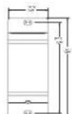
ZC-4, BOB and Fire

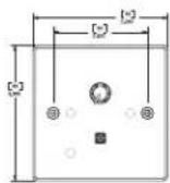
ZC-1,2,3,6,7,8 and 9 EU. VERSION


18-1342-D

ZC-B and 9
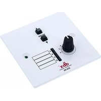
Brand : DBX
Model : ZC-1
Category : Controller