
PGXD4 - Receiver SHURE - Free user manual and instructions
Find the device manual for free PGXD4 SHURE in PDF.


| Product Type | Wireless Receiver |
| Brand | Shure |
| Model | PGXD4 |
| Dimensions (H x W x D) | 1.73 x 8.27 x 6.1 inches (44 x 210 x 155 mm) |
| Weight | 0.84 lbs (0.38 kg) |
| Power Supply | 12-18 VDC, 600 mA (external power adapter included) |
| Frequency Band | 2.4 GHz |
| Operating Range | Up to 200 ft (60 m) line-of-sight |
| Number of Channels | 20 |
| Audio Outputs | XLR (balanced) and 1/4" (6.35 mm) TRS (unbalanced) |
| Antenna Type | Dual internal antennas |
| Compatible Transmitters | PGXD1 bodypack and PGXD2 handheld |
| Audio Resolution | 24-bit / 48 kHz |
| Latency | < 2.9 ms |
| Mounting | Single rackmount (1/2 rack width) with included brackets |
| Cleaning and Maintenance | Wipe with a dry, soft cloth. Do not use solvents. |
| Safety | Use only the supplied power adapter. Do not expose to rain or moisture. |
| Spare Parts and Repairability | Contact Shure customer service or authorized service center for repairs and parts. |
| General Information | Digital wireless receiver for live sound and install applications. |
Frequently Asked Questions - PGXD4 SHURE
User questions about PGXD4 SHURE
0 question about this device. Answer the ones you know or ask your own.
Ask a new question about this device
Download the instructions for your Receiver in PDF format for free! Find your manual PGXD4 - SHURE and take your electronic device back in hand. On this page are published all the documents necessary for the use of your device. PGXD4 by SHURE.
USER MANUAL PGXD4 SHURE
PGXD -- Wireless System
Quick Start
SHURE®
PGXD Wireless
Quick Start Guide
Mise en service rapide
natural_image
Line drawing of a cable with plug and socket, showing connections to an electrical outlet (no text or symbols)connect receiver power cable
②
MIC OUT
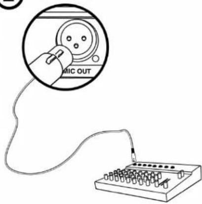
INSTRUMENT OUT
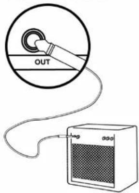
connect mixer or amplifier


2 × AA
add transmitter batteries
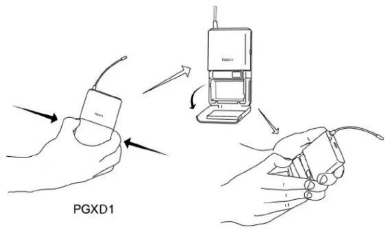
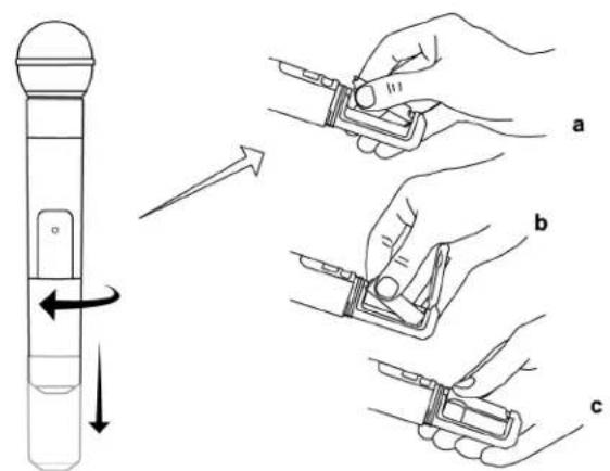
PGXD2


power
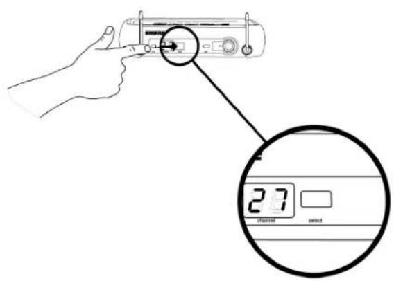
scan for a clear channel and power up



select
channel
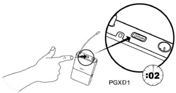
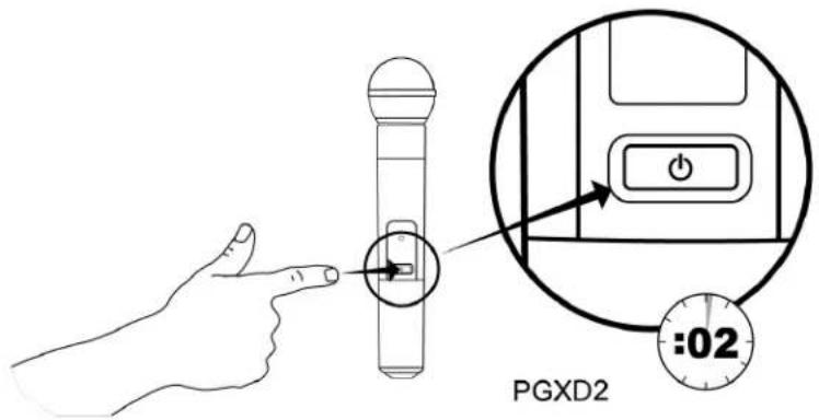
⑤

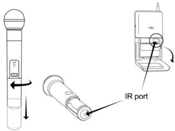
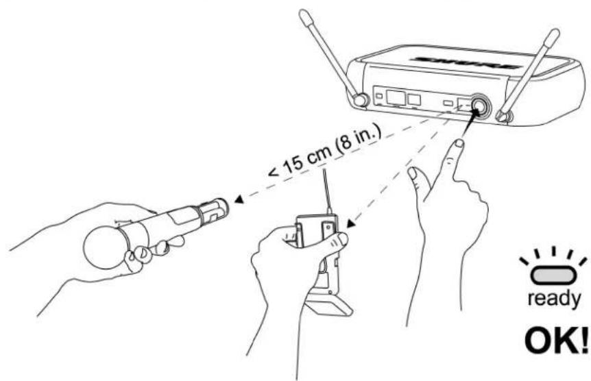
Sync
General Description
Offering uniquely tailored wireless solutions for vocalists, guitarists, and presenters, PGX-Digital combines the trusted legacy of Shure wired microphones with state-of-the-art, 24-bit digital wireless technology to deliver strong, clean RF performance. The result is wireless audio that sounds like wired, rock-steady RF signal even at extended distances, and plug-and-play setup and operation.
• Professional quality 24-bit digital audio
• Digital RF technology for rock-solid performance
- Wide variety of rugged and dependable Shure microphones
- One-touch setup and operation
- Up to 10 hours of battery life (9 hours, PGXD2)
- Up to 200 foot range (line-of-sight)
- 900 MHz operation—free from white spaces or DTV interference
System Components
All systems include
- PGXD4 receiver
• 2 AA alkaline batteries - Power supply
- User guide
Vocalist systems include
• PGXD2 handheld transmitter
- Microphone head (choice of PG58, SM58®, SM86, Beta 58A® or Beta 87A*) Available only in select markets
- Microphone clip
Lavalier, Headworn, and Instrument systems include
• PGXD1 bodypack transmitter
- Microphone (choice of WL93, WL185, PG30 or Beta 98H/C)
Guitar systems include
• PGXD1 bodypack transmitter
- 1/4" to mini 4-pin guitar cable (WA302)
Receiver Controls and Connectors
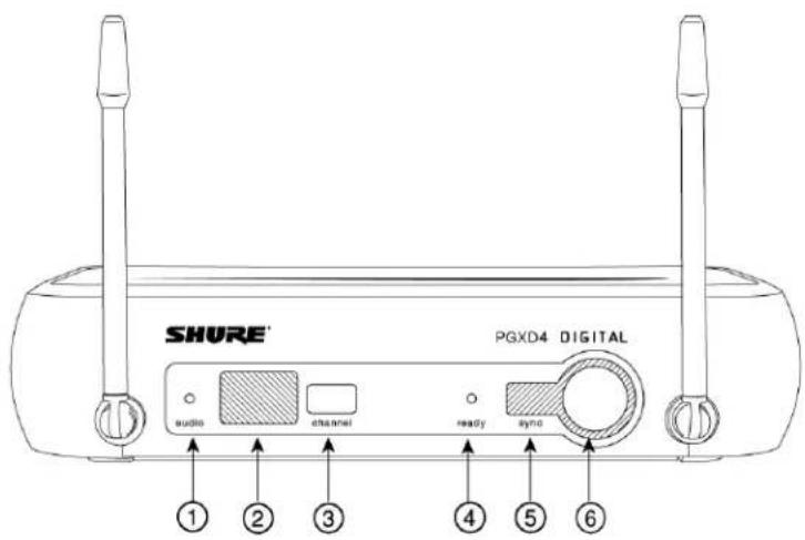
Front Panel
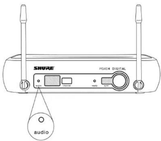
- audio LED: Indicates strength of incoming audio signal: green for normal, amber for strong and red for clipping.
- LED Screen: Displays group and channel setting. See "Single System Setup" for details.
- channel button: Changes group and channel setting. See "Single System Setup" for details.
-
ready LED: Indicates system ready and receiving an RF signal from the transmitter. Also indicates battery level of the transmitter:
-
Green = transmitter battery level normal
- Red = low battery (typically less than 60 minutes with alkaline batteries)
with NiMH rechargeable batteries, when the indicator turns red there will be little to no remaining life.
- Infrared (IR) port: Sends IR signal to transmitter for sync.
- sync button: Press to synchronize transmitter with receiver group and channel settings.
- AC adapter jack
- Adapter cord tie-off
- XLR microphone output jack
- 6.35 mm ( 14 ) instrument level output jack
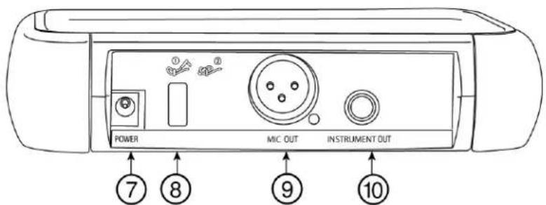
Back Panel
Transmitter Controls and Connectors
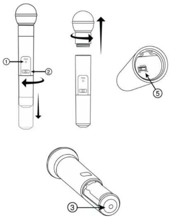
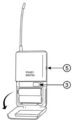
① Indicator LED: Displays battery level, mute, and IR transmission status (see table).
② Power/Mute Switch: Press to mute or unmute. Press and hold to power on or off.
③ Infrared (IR) port: Receives infrared beam to synchronize frequencies. When using multiple systems, only one transmitter IR port should be exposed at a time.
④ 4-Pin Microphone Input Jack
⑤ Audio Gain Adjustment
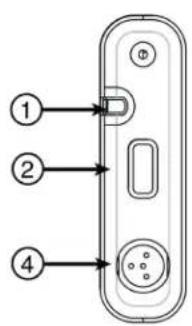
Transmitter Indicator LED
| LED Indicator Status | |
| Green Ready | |
| Flashing green Controls locked | |
| Amber Mute on | |
| Solid red Battery power low | |
| Flashing red Batteries dead (change batteries to power on transmitter) | |
| Rapidly flashing red IR transmission in process | |
| Flashing amber and red Battery power low and mute on |
Batteries
- A fresh set of alkaline batteries lasts up to 10 hours (9 hours, PGXD2).
- The transmitter LED and the receiver ready LED glow red to indicate low battery (typically less than 60 minutes remaining).
- NiMH rechargeable batteries may be used. However, the low battery indicator functions differently. When it turns red, there may be little to no remaining life.
- When the LED flashes red, the batteries must be replaced to power on the transmitter.
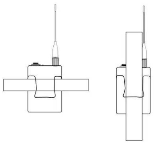
Wearing the Bodypack Transmitter
Clip the transmitter to a belt or slide a guitar strap through the transmitter clip as shown.
For best results, the belt should be pressed against the base of the clip.
natural_image
Two technical line drawings of mechanical components with no visible text or symbolsAdjusting Levels
Adjusting Gain
For best audio quality, set transmitter gain so the audio LED on the receiver flickers green and amber during the performance. Decrease gain if the signal clips (LED turns red).
The amber LED may appear to be red when viewed at an angle. For best results, monitor the LED from directly in front.
Bodypack Transmitter
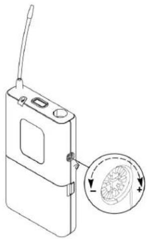
The bodypack has 26 dB of audio gain adjustment.
- Increase gain (clockwise +) for microphones
- Decrease gain (counterclockwise –) for guitars or high-output instruments
natural_image
Line drawing of a portable electronic device with a circular inset showing a fan blade (no text or symbols)Handheld Transmitter
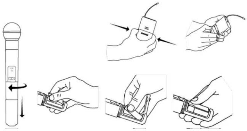
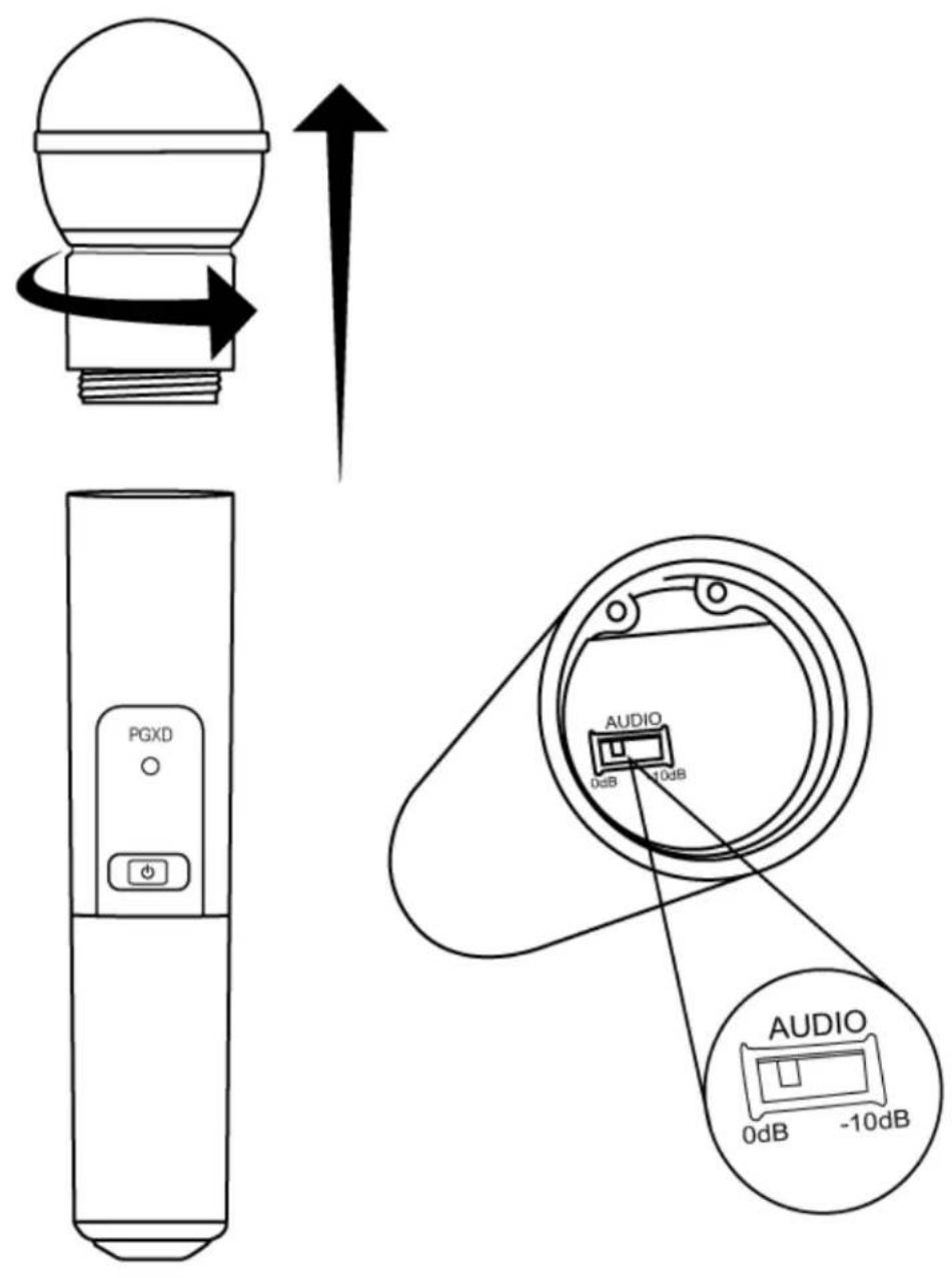
Access the gain switch by unscrewing the head of the microphone.
Use the tip of a pen or a small screwdriver to move the switch.
• 0dB: For quiet to normal vocal performance.
- -10dB: Use only if audio is distorted due to high vocal levels.
Single System Setup
-
Scan: Use the scan feature on the receiver to find a clear channel.
-
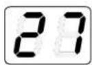
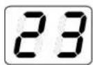
LED screen displays current channel
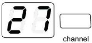
- Press channel button to scan for a clear channel
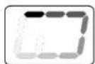
- System scans for the channel with the least interference

flowchart
graph LR
    A["0"] --> B["["]]
    B --> C["03"]
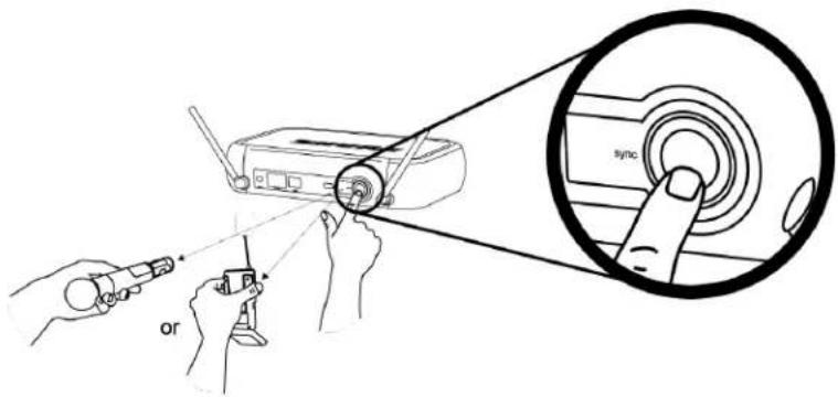
- Synchronize: Synchronize the transmitter to the receiver by aligning the infrared (IR) ports and pressing the sync button. Make sure the IR ports are closely aligned. After a successful sync, the transmitter LED momentarily flashes red and the receiver ready light illuminates.
This wireless system may be affected by RF interference when used in proximity to other wireless devices such as cordless phones, baby monitors, and two-way radios. For best results, use the scan and sync feature before each use or if you experience problems.
Multiple System Setup
Use the following steps to ensure the best performance when installing multiple wireless systems at the same location.
- Turn all receivers on and all transmitters off.
Turn on any other digital equipment that could cause interference during the performance so it will be detected during the frequency scans in the following steps. - Make sure the group number is the same for all receivers (see Manual Group Selection).
-
Perform a scan using the first receiver.
-
Turn on the first transmitter and sync it to the receiver.
- Repeat for each system.
After syncing each transmitter, leave it on so that scans from the other receivers will not select that channel.
- Be sure only one transmitter IR port is exposed when synchronizing each system.
Compatible Frequencies
When operating multiple systems simultaneously, choose one group from the following table and set all systems to different channels within that group.
| Number of Systems | Group (by band) | ||
| X8 X8A (Australia) X8B (Brazil) | |||
| 2 | 0 to 9 0 to 9 0 to 9 | ||
| 3 3 to 9 3 to 9 3 to 9 | |||
| 4 3 to 9 -- 3 to 9 | |||
| 5 7 to 9 -- -- | |||
Manual Channel and Group Selection (receiver only)
Using the receiver to scan for a channel is the best way to find the best frequency for your system. However, for multiple system setup, you may need to manually set the group number.
- Press and hold the channel button.
- Hold the button until the channel or group display begins flashing.
- Release and press the button again to advance the setting. At the desired channel or group number, wait for the flashing to stop. This activates the new setting.
- Transfer the new frequency setting to the transmitter using the automatic sync function.
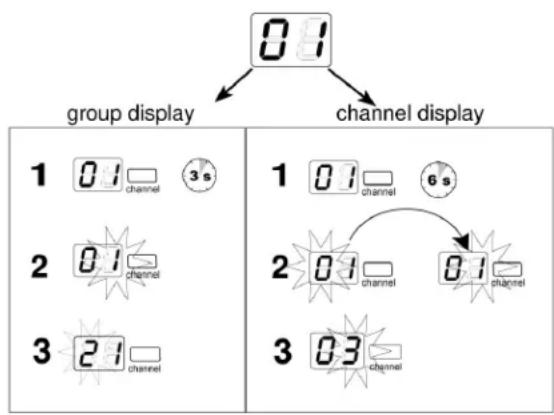
flowchart
graph TD
    A["0:1"] --> B["group display"]
    A --> C["channel display"]
    D["1 0:1 channel 3s"] --> E["2 0:1 channel"]
    D --> F["3 2:1 channel"]
    G["1 0:1 channel 6s"] --> H["2 0:1 channel 8:1 channel"]
    G --> I["3 0:3 channel"]
Locking and Unlocking Controls
Locking the system controls prevents accidental muting or channel adjustment during performances.
Transmitter
To lock the controls: With the transmitter off, hold the power button down until the green LED flashes (\~5 seconds)
To unlock the controls: With the transmitter on, hold the power button down until the green LED flashes (\~5 seconds)
Receiver
To lock the channel: Hold the channel button until the numbers flash (\~10 seconds)
To unlock the channel: Hold the channel button until the numbers flash (\~5 seconds)
Troubleshooting
| Issue Indicator Status Solution | ||
| No sound or faint sound | Receiver ready LED on | Verify all sound system connections |
| Receiver ready LED off • Turn on transmitterMake sure the batteries are installed correctlyPerform automatic transmitter setupInsert fresh batteries | ||
| Receiver LED screen off Make sure AC adapter is securely plugged into electrical outlet | ||
| Transmitter indicator LED flashing red | Replace transmitter batteries | |
| LED screen shows dash and value Error code displayed. Contact your Shure reseller for assistance. | ||
| Transmitter LED flashes red for 7 seconds after attempting to sync | Transmitter and receiver incompatible. Contact your Shure reseller for assistance. | |
| Noise bursts or audio dropouts N/A | · Change receiver and transmitter | to a different channel· Remove nearby sources of RF interference such as cordless or cell phones, computers, wireless routers, media players, digital signal processors, and security systems.· Replace transmitter batteries· If using multiple systems, change the frequency of one of the active systems |
| Distortion Audio LED on receiver indicates clipping (red) | Reduce transmitter gain | |
| Distortion increases gradually over time | Transmitter power light glowing or flashing red | Replace transmitter batteries |
| Sound level different from ca-bled guitar or microphone or when using different guitars | N/A Adjust transmitter gain as necessary | sary |
| Cannot turn transmitter on Transmitter LED slowly flashing red | Replace transmitter batteries | |
| Contact your Shure reseller for assistance | ||
Specifications
Working Range Line of Sight
60m (200 ft) ^[1]
RF Carrier Range
| X8 902–928 MHz | |
| X8A 915–928 MHz | |
| X8B | 902–907.5 MHz, 915–928 MHz |
Audio Frequency Response
20 to 20,000 Hz
System Gain
| PGXD1 6.35 | mm Connector 0 dB at minimum gain setting |
| XLR output -12.5 dB at minimum gain setting | |
| PGXD2 XLR output: -54.5 dBV/Pa at -10 dB gain setting | |
Total Harmonic Distortion
<0.02%, A-weighted, typical
Dynamic Range
108 dB, A-weighted
Operating Temperature Range
-18°C (0°F) to +50°C (122°F)
Transmitter Audio Polarity
Positive pressure on microphone diaphragm produces positive voltage on pin 2 with respect to pin 3 of low-impedance output and the tip of the high impedance 1/4-inch output
Audio Input Level
| at minimum gain setting +10 dBV maximum | |
| at maximum gain setting -16 dBV maximum |
Gain Adjustment Range
26 dB
Input Impedance
1 MΩ
RF Output Power
10 mW
Pin Assignments
| 1 ground (cable shield) |
| 2 + 5 V Bias |
| 3 audio | |
| 4 On instrument adapter cable, pin 4 floats | |
Dimensions
108 mm x 64 mm x 19 mm
Weight
128 g (4.5 oz.) (without batteries)
Housing
Molded Polycarbonate Case
Power Requirements
2 AA size alkaline or rechargeable batteries
Battery Life
up to 10 hours
Audio Input Level
| at minimum gain setting +10 dBV maximum | |
| at maximum gain setting -16 dBV maximum |
Gain Adjustment Range
26 dB
Input Impedance
1 MΩ
RF Output Power
10 mW
Pin Assignments
| 1 ground (cable shield) | |
| 2 + 5 V Bias | |
| 3 audio | |
| 4 On instrument adapter cable, pin 4 floats | |
Dimensions
108 mm x 64 mm x 19 mm
Weight
128 g (4.5 oz.) (without batteries)
Housing
Molded Polycarbonate Case
Power Requirements
2 AA size alkaline or rechargeable batteries
Battery Life
up to 10 hours
Dimensions
40 mm x 181 mm x 104 mm
Weight
289 g (10.2 oz.)
Housing
ABS
Sensitivity
-102 dBm at 10^-5 BER
Power Requirements
12-18 V DC at 150 mA, supplied by external power supply (tip positive)
Audio LED
| Red 2 dB below clip | |
| Amber 12 dB below clip | |
| Green 50 dB below clip |
Configuration
Impedance Balanced
Maximum Audio Output Level
| XLR connector -2.5 dBV | |
| 6.35 mm Connector +10 dBV |
Impedance
| XLR 50 Ω | |
| 6.35 mm Connector 50 Ω |
Pin Assignments
| XLR 1=ground, 2=audio, 3=no audio | |
| 6.35 mm (1/4") TRS Tip=audio, Ring=no audio, Sleeve=ground | |
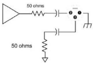
XLR Output
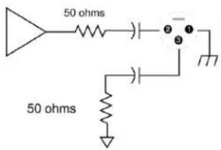
14 " Output
Certifications
PGXD1, PGXD2, PGXD4
Approved under the Declaration of Conformity (DoC) provision of FCC Part 15.
Operation of this device is subject to the following two conditions: (1) this device may not cause interference, and (2) this device must accept any interference, including interference that may cause undesired operation of the device.
LICENSING INFORMATION
Licensing: A ministerial license to operate this equipment may be required in certain areas. Consult your national authority for possible requirements. Changes or modifications not expressly approved by Shure Incorporated could void your authority to operate the equipment. Licensing of Shure wireless microphone equipment is the user's responsibility, and licensability depends on the user's classification and application, and on the selected frequency. Shure strongly urges the user to contact the appropriate telecommunications authority concerning proper licensing, and before choosing and ordering frequencies.
Information to the user
This equipment has been tested and found to comply with the limits for a Class B digital device, pursuant to Part 15 of the FCC Rules. These limits are designed to provide reasonable protection against harmful interference in a residential installation. This equipment generates uses and can radiate radio frequency energy and, if not installed and used in accordance with the instructions, may cause harmful interference to radio communications. However, there is no guarantee that interference will not occur in a particular installation. If this equipment does cause harmful interference to radio or television reception, which can be determined by turning the equipment off and on, the user is encouraged to try to correct the interference by one or more of the following measures:
- Reorient or relocate the receiving antenna.
- Increase the separation between the equipment and the receiver.
- Connect the equipment to an outlet on a circuit different from that to which the receiver is connected.
- Consult the dealer or an experienced radio/TV technician for help.
Note: EMC conformance testing is based on the use of supplied and recommended cable types. The use of other cable types may degrade EMC performance.
Changes or modifications not expressly approved by the manufacturer could void the user's authority to operate the equipment.
Australia Warning for Wireless
This device operates under an ACMA class licence and must comply with all the conditions of that licence including operating frequencies. Before 31 December 2014, this device will comply if it is operated in the 520-820 MHz frequency band. WARNING: After 31 December 2014, in order to comply, this device must not be operated in the 694-820 MHz band.
- PGXD -- Wireless System
- Quick Start
- SHURE®
- PGXD Wireless
- Quick Start Guide
- General Description
- System Components
- All systems include
- Vocalist systems include
- Lavalier, Headworn, and Instrument systems include
- Guitar systems include
- Receiver Controls and Connectors
- Front Panel
- Transmitter Controls and Connectors
- Transmitter Indicator LED
- Batteries
- Wearing the Bodypack Transmitter
- Adjusting Levels
- Adjusting Gain
- Bodypack Transmitter
- Handheld Transmitter
- Single System Setup
- Multiple System Setup
- Compatible Frequencies
- Manual Channel and Group Selection (receiver only)
- Locking and Unlocking Controls
- Specifications
- Audio Frequency Response
- Total Harmonic Distortion
- Dynamic Range
- Operating Temperature Range
- Transmitter Audio Polarity
- Gain Adjustment Range
- Input Impedance
- RF Output Power
- Dimensions
- Weight
- Housing
- Power Requirements
- Battery Life
- Sensitivity
- Configuration
- Certifications
- PGXD1, PGXD2, PGXD4
- LICENSING INFORMATION
- Information to the user
- Australia Warning for Wireless
Brand : SHURE
Model : PGXD4
Category : Receiver