
DS-A71024R-CVS - Server Hikvision - Free user manual and instructions
Find the device manual for free DS-A71024R-CVS Hikvision in PDF.


| Product Type | Cloud Video Storage Node (CVSN) |
| Model | DS-A71024R-CVS |
| Brand | Hikvision |
| Form Factor | 2U Rackmount |
| Processor | Intel i3/i7/Xeon E5-2620 or equivalent |
| RAM | 16 GB DDR3 (minimum) |
| Hard Drive Bays | 24 hot-swappable 3.5" SATA/SAS |
| Network Interfaces | 2 x Gigabit Ethernet (10/100/1000) |
| Power Supply | Redundant hot-plug (1+1), 300W-500W |
| RAID Support | RAID5, RAID6 (via system format) |
| Operating System | Linux Suse 10-64bit (pre-installed) |
| Storage Capacity | Up to 24 disks, supports large capacity drives |
| Main Functions | Video/picture/file cloud storage, smart stream, recording management, retrieval, backup, and lock |
| Maintenance | Hot-swap disks, RAID reconstruction, online firmware upgrade via web interface |
| Safety Features | Redundant power, disk failure alarm, cluster HA with virtual IP |
| Spare Parts | Hard drives, power supply modules, cooling fans |
| Management Interface | Web-based (HTTPS on port 2004 or 5119) |
| Compatibility | Works with Hikvision CVMN management nodes and iVMS-5120 platform |
| Dimensions (Approx.) | 88 mm x 482 mm x 700 mm (HxWxD) |
| Weight (Approx.) | 28 kg (fully populated with disks) |
Frequently Asked Questions - DS-A71024R-CVS Hikvision
User questions about DS-A71024R-CVS Hikvision
0 question about this device. Answer the ones you know or ask your own.
Ask a new question about this device
Download the instructions for your Server in PDF format for free! Find your manual DS-A71024R-CVS - Hikvision and take your electronic device back in hand. On this page are published all the documents necessary for the use of your device. DS-A71024R-CVS by Hikvision.
USER MANUAL DS-A71024R-CVS Hikvision
natural_image
Exterior view of a modern glass building with reflective windows and structural framework (no signage or text visible)iVMS-5120-V2.0-HikCStor Operation Manual
Hangzhou Hikvision Digital Technology Co., Ltd Wuhan Research and Development Center http://www.hikvision.com
Thank you very much for purchasing the products. Please contact us if you have some questions or needs.
This operation manual is applied to iVMS-5120-V2.0-HikCStor.
This operation manual may contain technical inaccuracies, some places where product functions don't correspond with operation or print errors. We will update the content according to the product functions and regularly modify and update the product or procedures described in this manual. The updated content will be added to the new version of this manual without further notice.

Attention of Smart Cloud Storage System
■ Cannot modify IP address and time of the server if the system deployment is completed.
■ Calibrate the time for all the sub-modules when deploying all the sub-systems to reduce the time difference for each module in the system
When cloud storage management nodes are configured and work normally, adjust the hardware devices according to the certain order. Make sure to shorten the interruption time for the cluster to provide service, please contact the relevant technical personnel about the specific operation sequence.
Content
1 Overview....1
1.1 Introduction of Smart Cloud Storage Product.... 1
1.2 Term Interpretation 2
1.3 Product Function....2
1.3.1 Smart Cloud Storage-Video Function 2
1.3.2 Smart Cloud Storage-Picture Function 5
1.3.3 Smart Cloud Storage-File Function 6
1.3.4 Smart Cloud Storage-Smart Stream Function....6
1.3.5 Smart Cloud Storage-System Management Function 7
1.3.6 Smart Cloud Storage-Operation and Maintenance Management Function 8
1.4 Smart Cloud Storage System Deployment Structure Diagram....9
1.4.1 Standard Cloud 9
2 Standard Cloud System Deployment....11
2.1 Preparation before Installation....11
2.1.1 Hardware Environment....11
2.1.2 Software Environment....11
2.2 Storage Point Deployment....11
2.2.1 CVSN Internet Configuration....11
2.2.2 CVSN Disk Initialization.... 14
2.2.3 Ordinary Storage CVSN Node Deployment....15
2.3 Management Node Deployment 22
2.3.1 Installation of Management Node Deployment System 22
2.3.2 Installation of Management Node Software 22
2.4 Standard Double Clouds Machine HA Formation 24
2.4.1 Bind Net Port 24
2.4.2 HA Cluster Formation And Initialization.... 25
2.4.3 HA Cluster Heartbeats Configuration.... 30
2.5 Establish Standard Cloud Cluster 31
2.5.1 Bind Network Interface 31
2.5.2 Establish & Initialize Standard Cloud Cluster 32
2.6 Configure Standard Cloud 35
2.6.1 Configure CVS 35
2.6.2 Create Domain 35
2.6.3 Modify Domain.... 36
2.6.4 Add CVS to Domain.... 36
2.6.5 Create Resource Pool.... 37
2.6.6 Modify Resource Pool 38
2.6.7 Configure CVA 40
2.6.8 Add CVA to Cluster 40
2.6.9 Modify CVA Parameter....41
2.6.10 Configure CCU 41
2.6.11 Configure Synchronization Server.... 42
2.6.12 Configure Group IP 43
2.6.13 Resource Pool User Management 44
2.6.14 Manage Bucket 46
3 Video storage configuration....49
3.1 Video Storage Configuration of the Public Security Platform.... 49
3.1.1 Add Server 49
3.1.2 Add Monitoring Device....53
3.1.3 Configure and Send down the Recording Schedule....57
4 Picture storage configuration 60
4.1 Platform archived....60
4.1.1 Capture camera front-end configuration....60
4.1.2 Platform configuration....60
5 Cloud storage functions introduction....76
5.1 Recording schedule query....76
5.2 Video recording 77
5.2.1 Video query, playback, Downloading....77
5.2.2 Video locking....78
5.2.3 Video backup 80
5.2.4 Recording annotation....80
5.2.5 Search by Date/Month 80
5.2.6 High speed downloading 82
5.3 Smart stream 82
5.3.1 Smart stream query 82
5.3.2 Smart stream downloading 83
5.3.3 Smart retrieval....83
5.4 Bayonet pictures 84
5.4.1 Picture storage....84
5.4.2 Picecture downloading 85
5.4.3 Picture Locking....85
5.4.4 Picture searching by picture....86
5.5 File 86
5.5.1 File upload 86
5.5.2 File query....87
5.5.3 File downloading 87
5.5.4 File copy 88
5.5.5 File permission setting 89
5.5.6 File deletion 89
5.6 System running log Downloading 89
1.1 Introduction of Smart Cloud Storage Product
With the large-scale application of high-definition video, security video surveillance system is larger and larger. The data types stored in the system are various and the complexity of the industry application improves constantly. Video data need to be stored in the storage system for a long time and require the accurate invoking at any time, which put forward new requirements on the reliability and performance of the storage system. In the complex system in the future, the data will grow explosively, so it is particularly important to provide fast storage and retrieval technology for massive data. The storage system is becoming the decisive factor in the future development of video surveillance technology.
In the face of the massive storage requirements of EB level growth in recent years, the capacity and performance of the traditional NVR, SAN or NAS will be a bottleneck. However, cloud storage can break through the bottleneck, but also achieve a linear expansion of performance and capacity, which is a new choice for government and enterprise users of pursuing high performance and availability.
Cloud storage is a new concept which extended and developed based on Cloud Computing which is a system of providing external data storage and service access functions. Through the application of cluster, grid technology or distributed file system, cloud storage apply storage virtualization technology to store a large number of different types of various network volumes with the application software to work together. So cloud storage is considered as the cloud computing system of configuring large capacity storage volume.
Based on the technical and functional characteristics of cloud storage, Hikvision designs a set of Hikvision smart cloud storage system which specifically for the storage and management of large capacity video data, meets the special application requirements of video surveillance and
application requirements of file storage. (Hikvision smart cloud storage called in following sections)
Through the combination of cloud storage technology, intelligent application in surveillance and big data technology, Hikvision use the integration of hardware and software design to provide “security”, “intelligent” and “big data” professional storage services with uniform, flexible and safe characteristics.
1.2 Term Interpretation
| Name | Meaning |
| CVMN | Cloud Video Manage Node |
| CVSN | Cloud Video Storage Node |
| CVM | Cloud Video Manage |
| CVS | Cloud Video Storage |
| CVA | Cloud Video Access |
| CPM | Cloud Plan Manage |
| CDT | Cloud Data Transfer |
| CCU | Cloud Calculate Unit |
| ASSN | Asynchronous Storage Service Node |
| ASS | Asynchronous Storage Service |
| Domain | Composed of multiple storage nodes. The domain can be divided into lots of resource pools |
| Group | Composed of a number of storage nodes in a domain |
| IPC | IP Camera |
| Stand Cloud | Independent CVMN hardware device, installed CVM program and provides external service through the only virtual IP address |
1.3 Product Function
1.3.1 Smart Cloud Storage- Video Function
1. Recording Management Function
| Function | Function Description |
| Recording schedule Management | Link the Recording schedule on the platform and synchronize the Recording schedule to each storage node |
| Recording schedule Execution | Confirm the channel and storage address according to requirements and responsible for the write operation from recording data to lower module |
| Event recording | Perform recording tasks according to the specific event and the priority is higher than the timing recording |
- Video Storage Function
| Function | Function Description |
| Video Recording | Save the recording data from the front-end device by the system according to the user's plan. The recording type and header are specified by the user and the storage opens the related resources |
| Revise recording type dynamically: when acquiring the front-end video data, we can modify recording type according to the alarm type. Collected data after modifying preserves to the system immediately and reflects in the data type | |
| Video Retrieval | Search the recording data by the user through the encoder ID, recording type, time period, locking and label, etc. |
| Video Playback | Support playback about the recording data according to encoder ID, time period and recording type |
| Support the positioning of the playback time about the recording data according to encoder ID and time period | |
| Support fast and slow forward | |
| Support positive and reverse playback | |
| Support I frame playback | |
| Support to pause playback manually | |
| Support to stop playback manually | |
| Video Download | Support to download about the recording data according to encoder ID an time periodSupport to resume from the breakpoint |
| Support to stop download manually | |
| Video Locking | Support to lock the specified video and the locked data is not covered circularly |
| Support the locked video clips will unlock when the locking time expires | |
| Support to unlock the specified video clips manually | |
| Video Backup | Support the local cloud storage backup about recording data according to encoder ID and time periodSupport the different cloud storage backup about recording data according to encoder ID and time periodSupport backup automatically according to the number of redundant copies while recording |
| Video Annotation | Support to mark according to encoder ID and time period |
| Support to search, modify and delete the annotation information of the recording data | |
| Cover Circularly | Support coverage storage of the recording data according to the cycle and capacitySupport that cover circularly automatically when the remaining capacity of single storage node is insufficient |
| Video Additional Recording | Support to supplement lost video automatically when the flow and video writing is abnormalSupport sending down the history stream recording schedule and supplement history video from front-end regularlySupport supplementing history recording manually by the user |
| Main stream/Sub Stream Storage | Support to store main stream/sub stream according to the schedule optionally |
| Frame Extracting Storage | Support frame extracting storage according to recording data regularly(only store I frame) |
| Frame Extracting Display | Support to extract I frame according to the video recording and position effective information from massive video data accurately |
1.3.2 Smart Cloud Storage-Picture Function
| Function | Function Description |
| Picture Writing | Support direct cloud storage of picture from alarm server and picture serverSupport direct cloud storage of picture from capture machine |
| Picture Retrieval(URL preview) | Support picture preview according to the URLSupport a variety of compression methods of picture preview: percentage compression, size compression, width and height compression |
| Picture Download | Support to download the specified picture according to the URLSupport the bath download of the picture according to the number of monitoring points and the time periodSupport a variety of compression methods of picture download: percentage compression, size compression, width and height compression |
| Picture Locking | Support to lock the specified picture according to the URL and the locked data is not covered circularlySupport the bath locking of the picture according to the number of monitoring points and the time periodSupport that the locked picture will unlock when the time expires |
| Picture Cover | Support coverage storage of the picture data according to the cycle and capacityCover circularly automatically when the remaining capacity of single storage node is insufficient |
| Picture Backup | Support the local cloud storage backup about picture data according to encoder ID and time periodSupport the different cloud storage backup about picture data according to encoder ID and time periodSupport backup automatically according to the number of redundant copies when writing picture |
| Search Image by Image(support | Support to model and store model for the picture writingSupport model analysis according to picture writing and return to the picture |
| DS-A720XXR-CVS series) | URL of the high similarity |
1.3.3 Smart Cloud Storage-File Function
| Function | Function Description |
| File Upload | Support to upload files via URLSupport the metadata information of the setting filesSupport multiple copy storageSupport copy loss and automatic supplement |
| Support multi-step download for big object and resuming from break point | |
| File Permission Control | Support of file setting and modifying permissions. The supported permission: read and write, only read or privately |
| File Version Number Management | Support to manage the version number of the file and store multiple versions of the file according to the setting |
| File Copy | The existed file can be copied by the user and metadata information and the permissions of the file can be set again |
| File Retrieval | File data can be searched via file key |
| File Download | Support file download via URL |
| Support to resume from break point | |
| File Delete | Support to delete file via file key |
| File Expires Automatically | The expired file will be deleted by the system in the bucket automatically according to the setting bucket period by the user |
1.3.4 Smart Cloud Storage-Smart Stream Function
| Function | Function Description |
| Smart Stream Storage | Support to store smart stream of the stripped video separately when recording videoSupport to store smart stream and the corresponding video data according to the different periods |
| smart stream retrieval | Support to search the smart stream data according to the number of monitoring points and time period, etc. |
| smart stream download | Support to download the smart stream data according to the number of monitoring points and time periodSupport to resume from break pointSupport to download rapidly |
| smart retrieval | Smart event retrieval |
1.3.5 Smart Cloud Storage-System Management Function
| Function | Function Description |
| Cluster Management | Cluster mode is used by file index and has no single fault, which ensures the safety of the index data |
| Fast index management is used by the cluster and position rapidly according to the user's various query conditions (the number of the monitoring points, video type, time period, etc.) | |
| Load Balance Management | The virtual IP technology is used by the cluster and provides a unified entrance IP form externally. The access to the cluster shares via varieties of algorithms which reduce the access pressure of a single node |
| Monitor the pressure of the real-time back-end storage node and a single storage node can be migrated to other storage nodes when the pressure is too large, which achieves the balance between the entire cluster load | |
| Virtualization Management | Support unified management for the storage devices, regard virtualization as resource pool and manage the virtual resource which is divided into blocks |
| Automatic Simplification Management | Distribute storage space dynamically and adjust and distribute storage resource space in the system to improve the utilization of the system storage space |
| Distributed Storage Management | Through the specific algorithm front-end data will be distributed to each storage node, thereby reducing the pressure on the large number of playback for a single storage node |
| Hybrid Storage Management | (Video/picture/file/smart stream hybrid storage) |
| Online Extension | (Hard disk expansion)(Disk array expansion)(Server extension) |
| Storage Space Management | Support to distribute recording space for the camera randomly and the distributed space can be adjusted flexibly. Support to record file when the camera resumes recording |
| Permission Management | Multi-level user management. Bind the user and resource pool and limit the user's permissionThe abstract authentication and encryption mechanisms are used by interactive protocols to ensure the security of the network interactive protocols |
1.3.6 Smart Cloud Storage-Operation and Maintenance Management Function
| Function | Function Description |
| System Information Acquisition | Support system information: version, CPU, memory, network card, disk, etc. |
| System Fault Alarm | Support system fault(CPU, memory beyond the threshold) and cloud storage program exception, notify alarm to the operation and maintenance platform automatically |
| Storage Device Alarm | Support that the device fault and device offline will be notified to the operation and maintenance platform automatically |
1.4 Smart Cloud Storage System Deployment Structure Diagram
1.4.1 Standard Cloud
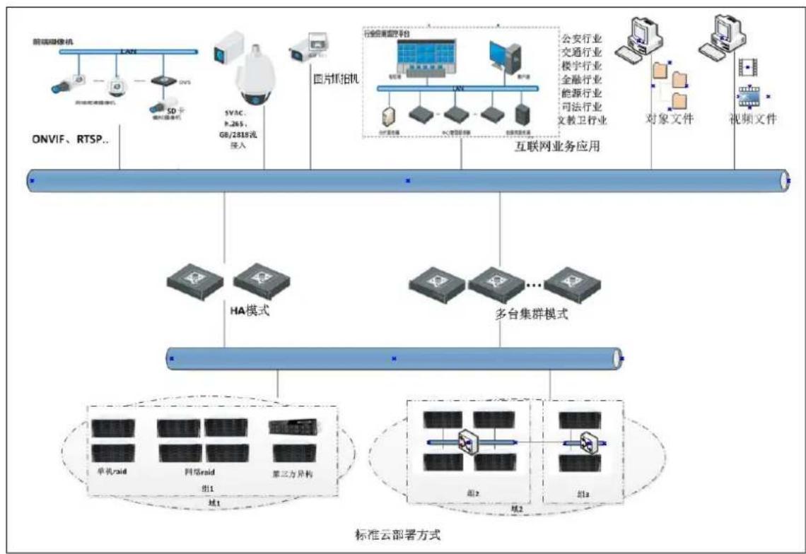
Hikvision standard cloud solution adopts the 'all' cluster program of the management server and storage equipment, management server is mainly responsible for the management of software and hardware resource, business scheduling and distribution, storage node is mainly responsible for data reading and writing. The architecture design can meet the needs of massive data storage and concurrent process of large and medium-sized projects, which provide high performance, high stability and high scalable storage services with video, picture, document and other types of data to the users.
Hikvision standard cloud program is mainly applied to the large and medium-sized projects, the point of the front-end is more than 1000, storage device is more than eight or projects which have high security storage and data analysis requirements
The architecture of the standard cloud system is as follows:
flowchart
```mermaid
graph TD
    A["前端摄像机"] --> B["ONVIF、RTSP.."]
    C["视频监控设备"] --> D["SD卡"]
    D --> E["视频监控设备"]
    F["图片斯拍机"] --> G["SVC: P.265, GB/2319流存入"]
    H["多台集群模式"] --> I["云部署方式"]
    J["云部署方式"] --> K["组1"]
    L["云部署方式"] --> M["组2"]
    N["云部署方式"] --> O["组3"]
    P["云部署方式"] --> Q["云部署方式"]
    R["云部署方式"] --> S["云部署方式"]
    T["云部署方式"] --> U["云部署方式"]
    V["云部署方式"] --> W["云部署方式"]
    X["云部署方式"] --> Y["云部署方式"]
    Z["云部署方式"] --> AA["云部署方式"]
    AB["云部署方式"] --> AC["云部署方式"]
    AD["云部署方式"] --> AE["云部署方式"]
    AF["云部署方式"] --> AG["云部署方式"]
    AH["云部署方式"] --> AI["云部署方式"]
    AJ["云部署方式"] --> AK["云部署方式"]
    AL["云部署方式"] --> AM["云部署方式"]
    AN["云部署方式"] --> AO["云部署方式"]
    AP["云部署方式"] --> AQ["云部署方式"]
    AR["云部署方式"] --> AS["云部署方式"]
    AT["云部署方式"] --> AU["云部署方式"]
    AV["云部署方式"] --> AW["云部署方式"]
    AX["云部署方式"] --> AY["云部署方式"]
    AZ["云部署方式"] --> BA["云部署方式"]
    BB["云部署方式"] --> BC["云部署方式"]
    BD["云部署方式"] --> BE["云部署方式"]
    BF["云部署方式"] --> BG["云部署方式"]
    BH["云部署方式"] --> BI["云部署方式"]
    BJ["云部署方式"] --> BK["云部署方式"]
    BL["云部署方式"] --> BM["云部署方式"]
    BN["云部署方式"] --> BO["云部署方式"]
    BP["云部署方式"] --> BQ["云部署方式"]
    BR["云部署方式"] --> BS["云部署方式"]
    BT["云部署方式"] --> BU["云部署方式"]
    BV["云部署方式"] --> BW["云部署方式"]
    BX["云部署方式"] --> BY["云部署方式"]
    BZ["云部署方式"] --> CA["云部署方式"]
    CB["云部署方式"] --> CD["云部署方式"]
    CE["云部署方式"] --> CF["云部署方式"]
    CG["云部署方式"] --> CH["云部署方式"]
    CI["云部署方式"] --> CJ["云部署方式"]
    CK["云部署方式"] --> CL["云部署方式"]
    CM["云部署方式"] --> CN["云部署方式"]
    CO["云部署方式"] --> CP["云部署方式"]
    CS["云部署方式"] --> CT["云部署方式"]
    CU["云部署方式"] --> CV["云部署方式"]
    CW["云部署方式"] --> CX["云部署方式"]
    CY["云部署方式"] --> CZ["云部署方式"]
    DA["云部署方式"] --> DB["云部署方式"]
    DC["云部署方式"] --> DD["云部署方式"]
    DJ["云部署方式"] --> DE["云部署方式"]
    DF["云部署方式"] --> DG["云部署方式"]
    DH["云部署方式"] --> DI["云部署方式"]
    DJX["云部署方式"] --> DJX["云部署方式"]
    DK["云部署方式"] --> DLX["云部署方式"]
    DM["云部署方式"] --> DMX["云部署方式"]
    DN["云部署方式"] --> DXX["X"]
Fig.1.4.1-1 The architecture of the standard cloud system
2 Standard Cloud System Deployment
2.1 Preparation Before Installation
2.1.1 Hardware Environment
| Device Name | Configuration |
| CVMN | Processor: Configuration≥ dual six-core processors, Dominant Frequency 2.0GHz; RAM: Configuration≥32GB DDR3; HDD: Configuration≥4 hot plug hard disks with 300GB 10K 2.5 ‘SAS’; Support more than 6 hard disks inserted; Internet: Provide≥ two gigabit Ethernet interface; Power Supply: Efficient hot plug redundant power supplies (1+1); |
| CVSN | Processor: Configuration≥i3/i7/E5-2620; RAM: Configuration≥16GB DDR3; HDD: Configuration≥16/24/36/48/60/72 disk bit hot-swappable hard disk; Internet: Provide≥ two gigabit Ethernet interface; Power Supply: Efficient hot plug redundant power supplies (1+1); |
2.1.2 Software Environment
| Device Name | Software |
| CVMN | Linux CentOS 7-64bit |
| CVSN | Linux Suse 10-64bit (save CVS 1.0.1 system) |
2.2 Storage Point Deployment
2.2.1 CVSN Internet Configuration
Prepare a new ordinary storage server or a double control storage server of Hikvision. Insert SATADOM card of the
latest version CVS1.0.1 into SATA slot. Pay attention to put the SATADOM card in front of SATA slot, otherwise, the system will go wrong.
- Modify IP address of the storage server. The method is as follows:
1) Using a gigabit network cable to connect the network port of the notebook computer with the management network port on the storage server. Set the notebook computer IP address same with port management network, for example: 10.254.254.100.
2) Make sure the network connection is normal (You can use the Ping 10.254.254.254 to test on laptop.). Open the browser of your laptop and type https://xx.xx.xx.xx:2004 (xx.xx.xx.xx is the storage server IP.). Enter to confirm then it will appear the front page of system, as shown in figure 2.2.1-1. There is the serial number of system equipment below the login interface.
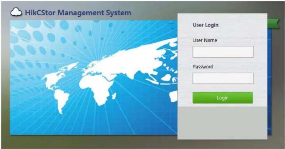
Figure 2.2.1-1 Storage Management System
3) Enter the user name and password and go to the storage server management interface.
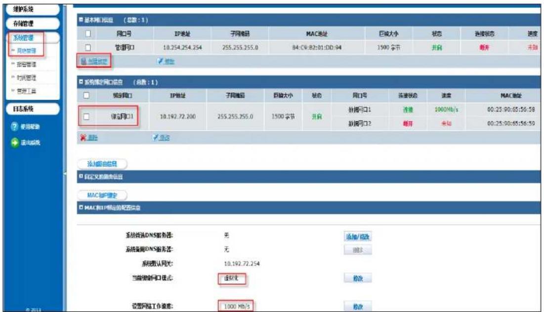
4) Go to the 'System -> Network Management' interface to modify data network port interface IP address of storage server. Suppose you want to modify the network interface IP to 10.192.77.30 of 1. You can check the network interface needing modification in the figure 2.2.1-2 and click 'Modify'. Then you can modify following information in the 'Modify Network Port Information' interface popped up:
● IP Address of New Network Port
- Subnet Mask
- Gateway
- Giant frame size: Choose bigger than 1500 bytes of the frame to improve the transmission performance. Using giant frame transmission needs the support of routers and other network equipment.
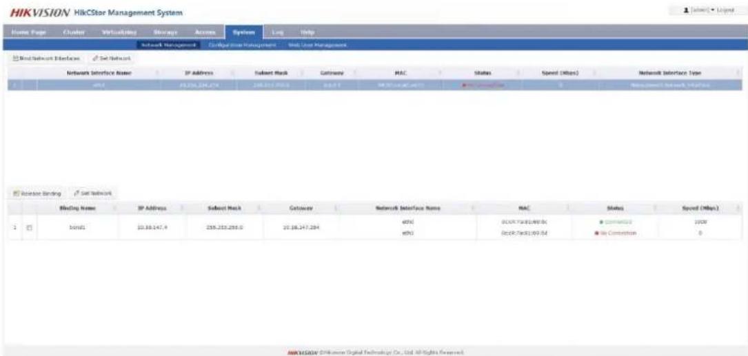
Figure 2.2.1-2 Set Network Interface IP
After modify storage server IP, you can type https://xx.xx.xx.xx:2004(xx.xx.xx.xx is the storage server IP.) on browser in the machines of same network segment to join Storage Management System.

Figure 2.2.1-3 Access IP in Storage Management System
If you need to bind network interface, refer to the following information:
Log on https://storageIP:2004. Go to 'System -> Network Management'. Check the network interface needed to bind. For example, check bond1 and bond2 and click 'Bind Network Interfaces'. Make sure the current network speed is '1000MB/s' and binding model is 'Virtualization'. If not, you should click 'Modify' as shown is figure 2.2.1-4.
Note: You need to restart the machine after modify the 'network speed' and 'binding model'.
2.2.2 CVSN Disk Initialization
After inserting hard disk into storage machine, go to the 'Storage -> CVS' interface in a HikCStor Management System. Click 'View Disk Information' and you will see the disk information as shown in figure 2.2.2-1.
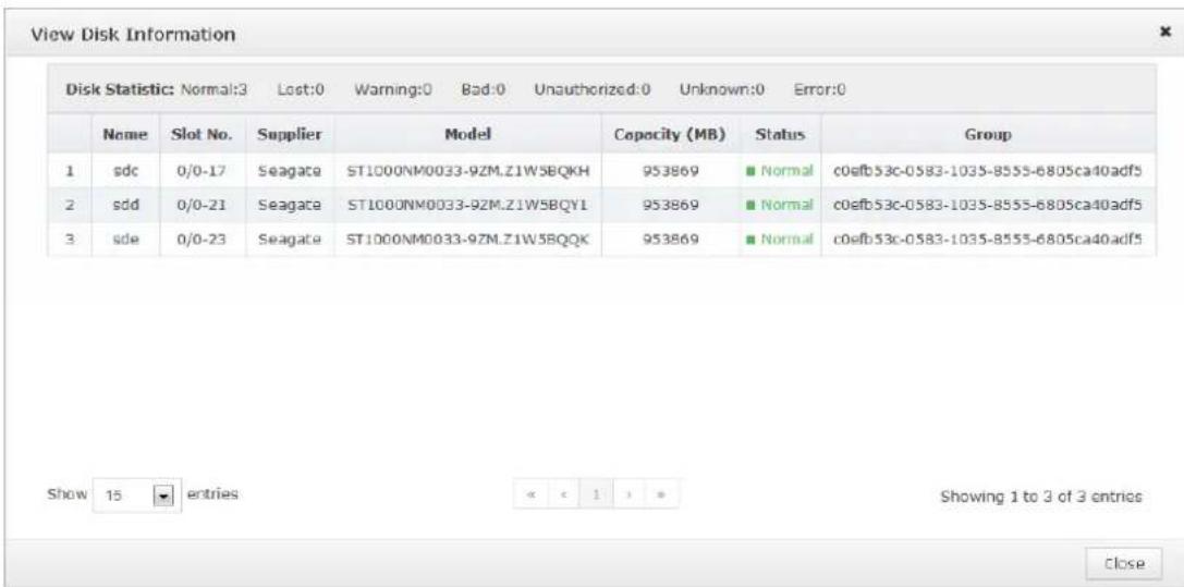
Figure 2.2.2-1 View Disk Information
For the first time to join the disk storage systems, it will show ‘Unauthorized’ if there is no storage disk testing standards for certification. It should pass the disk test before using as shown in figure 2.2.2-2.
Check the disk of ‘Unauthorized’, click ‘Detection’ and then click ‘start’ in the pop-up window. The disk status will appear ‘normal’ after the test successes.
The ‘Group’ will show ‘Uninitialized’ if the inserted disk is used before like figure 2.2.2-3.
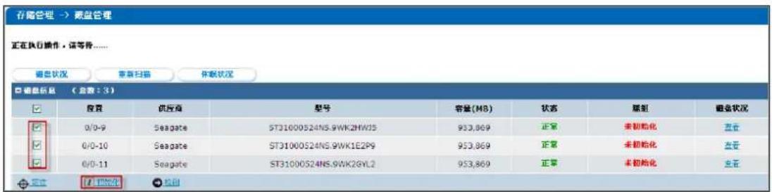
Check the column of 'Uninitialized' and click the 'Initialized' to empty the disk data.
2.2.3 Ordinary Storage CVSN Node Deployment
Based on the series equipment of Hikvision including DS-A71024R-CVS, DS-A71048R-CVS, DS-72024R-CVS, DS-72048R-CVS, this chapter will introduce CVSN node deployment for steps.
1. CVSN Software Installation
You should read 'CVSN Module Update Instruction' in
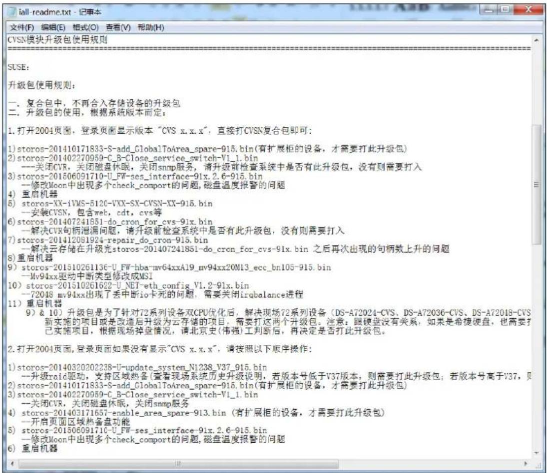
Go to https://xx.xx.xx.xx:2004 (xx.xx.xx.xx is the storage server IP.) to join 'System -> Network Management' interface. Click 'Upload BIOS' button.
Check the operation logs to make sure the upgrade package installation completed after the page appears 'Upload BIOS Successfully' (as shown below).
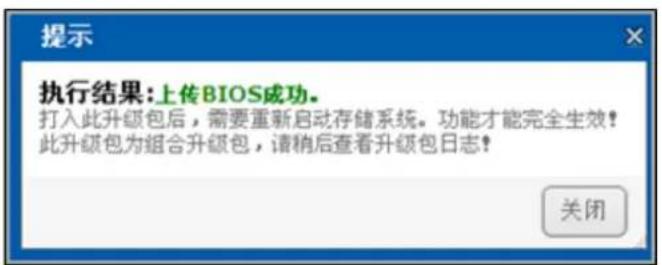
Figure 2.2.3-2 Upload BIOS Successfully
You should complete installing steps and restarting operation strictly referring to 'CVSN Module Update Instruction' in
2. CVSN System Format
You need to initialize the storage server in the cluster and add it to the management cluster when use it first
time. Only in this way management cluster can manage and use its storage resource.
The method of initializing Storage Server is as followed:
Go to https://xx.xx.xx.xx:5119 (xx.xx.xx.xx is the storage server IP.) to join 'Storage -> Storage Volume' interface. Click 'Format' button as followed:
HIKVISION HikCStor Management System
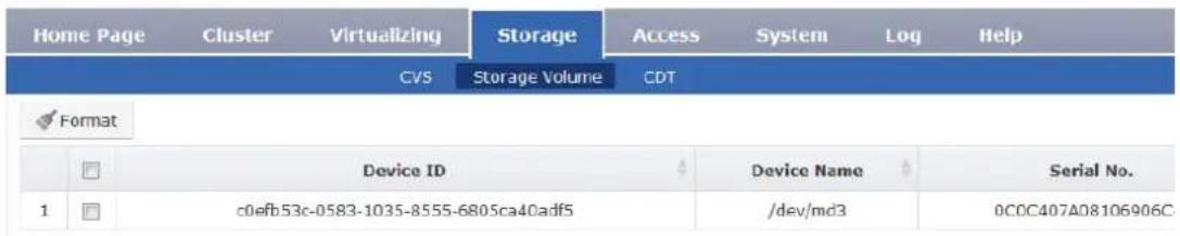
Figure 2.2.3-3 Format
Choose ‘Yes’ in ‘Force Format’ box. Choose ‘Only RAID’ in ‘Delete RAID’ box. Choose ‘RAID5’ or ‘RAID6’ in ‘RAID Type’ box. Choose the number of hot standby tray and click ‘Yes’ to complete as shown in figure 2.2.3-4.
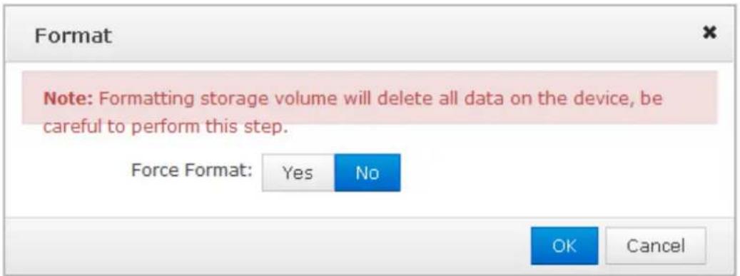
Figure 2.2.3-4 System Formatting Options
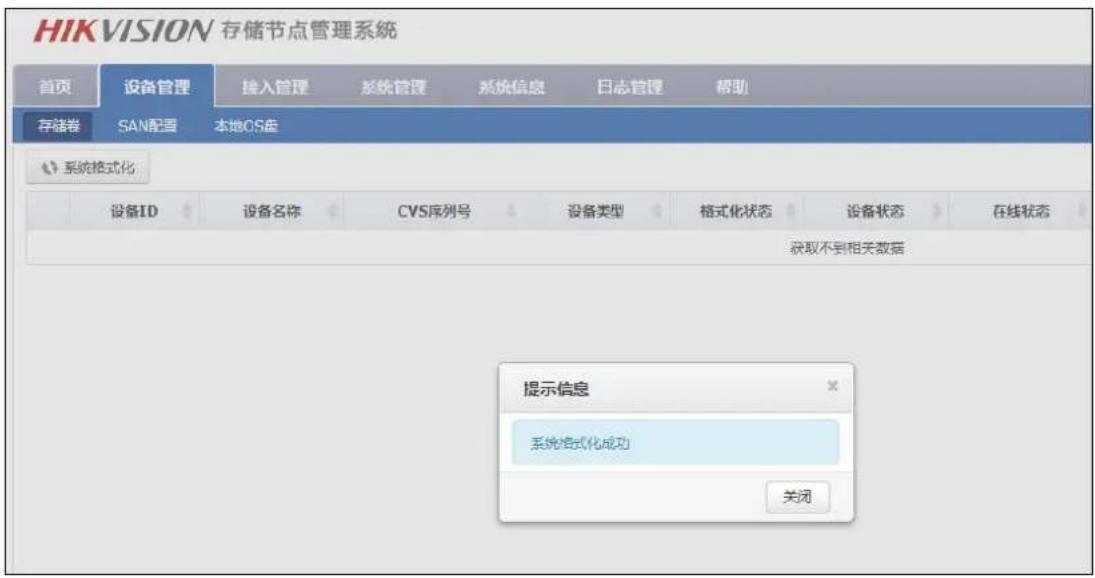
The array is created successfully if the page is shown as the figure 2.2.3-5.
There may be ‘OFF’ in ‘CVS Sever State’ of ‘Configuration Management’ as shown in Figure 2.2.3-6. (It is normal protected operation.).
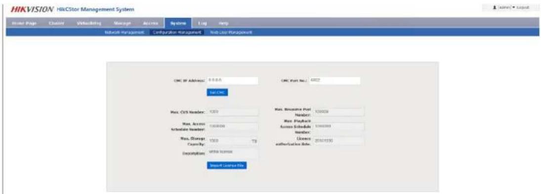
Figure 2.2.3-6.
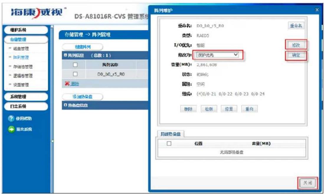
It is better to synchronize at night or on weekends after build Raid because this step needs several hours. Click ‘Force format’ and go to https://xx.xx.xx.xx:2004 (xx.xx.xx.xx is the storage server IP.) to join ‘Storage -> Array Management’ interface. Click ‘Maintain’ to make sure the synchronous speed setting of ‘Set Management’ is ‘High’ and modify the array attribute to ‘Protection Priority’ as shown in figure 2.2.3-7.
After array synchronization is completed, you can check it in 'Log -> Operation Log' as shown in figure 2.2.3-8.
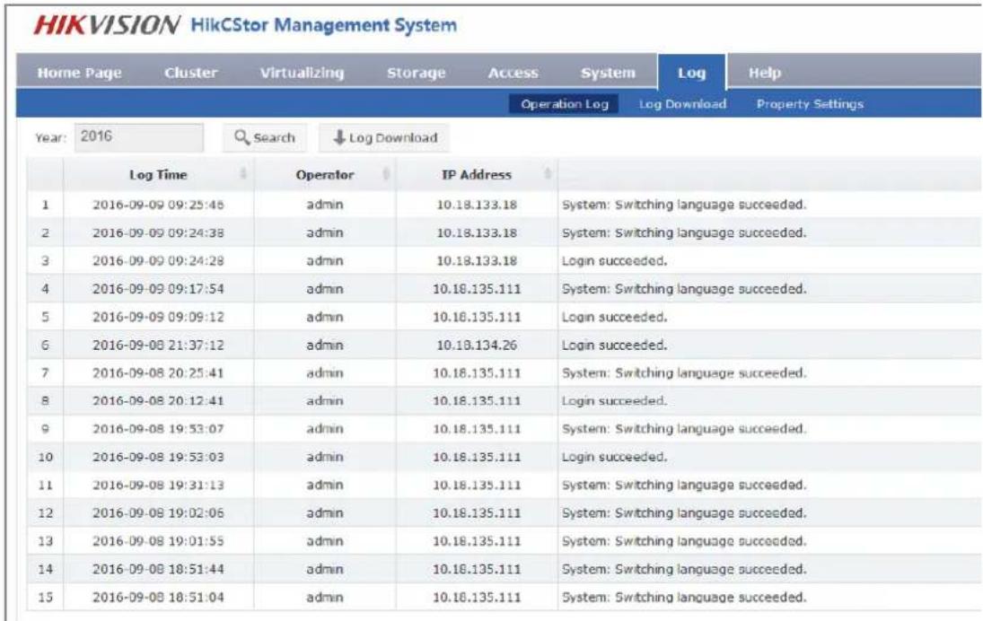
Figure 2.2.3-8 Array Synchronization Completed
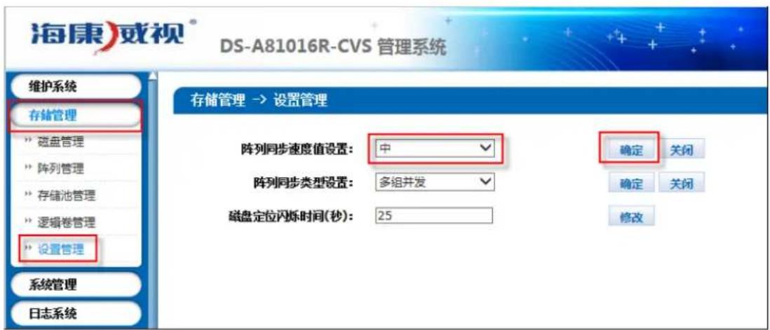
Check RAID and disk status of each CVS node, to see if the disk has been kicked out. Set the synchronous speed to 'Medium' as shown in figure 2.2.3-9.
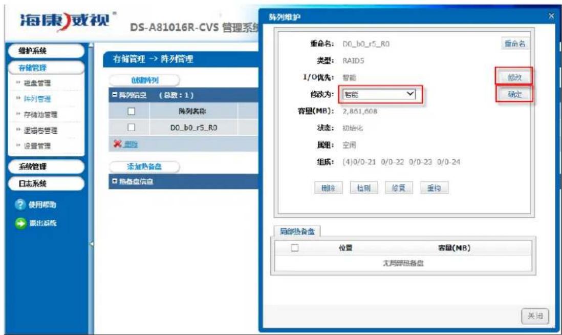
Set the array attribute to the default 'Smart' as shown in figure 2.2.3-10.
Check whether the array detection is closed in 2004 page after the package upgrade. If not, you must delete the array detection strategies in 'Maintenance -> Common Maintenance' page.
Do not need to shut down disk detection strategy as it has less effect on system performance.
Click the ‘Restart’ to restart the storage server in ‘Maintenance -> System Monitoring’, after RAID synchronization is completed.
Then go to https://xx.xx.xx.xx:2004 (xx.xx.xx.xx is the storage server IP.) to join 'Storage -> Storage Volume' interface. Click 'Format' at each storage volume and wait until it completed, as shown in figure 2.2.3-11.
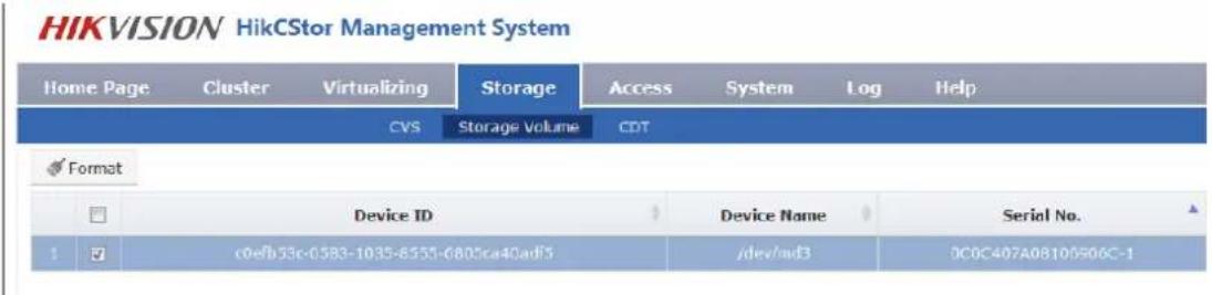
Figure 2.2.3-11 Block Device Format
3. CVA Installation
CVA is cloud storage access software. You should install the CVA when needing a distributed video program for active video requirements except the image project.
Installation steps are as follows:
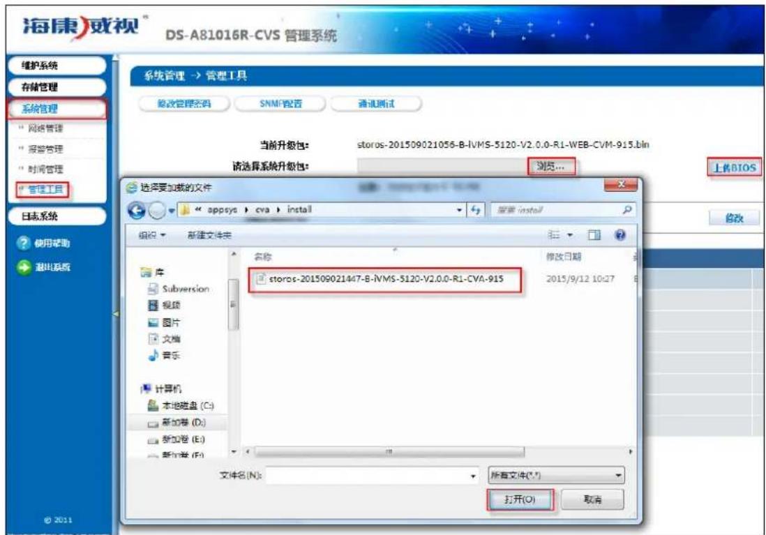
Go to https://xx.xx.xx.xx:2004 (xx.xx.xx.xx is the storage server IP.) to join 'System -> Management Tool' interface. Choose storos-xxxxxxxxxxxx-B-iVMS-5120-V2.x.x-Sx-CVA-915.bin to upgrade and view the Operation Log making sure it completed. Now you can run the CVA without restarting the server.
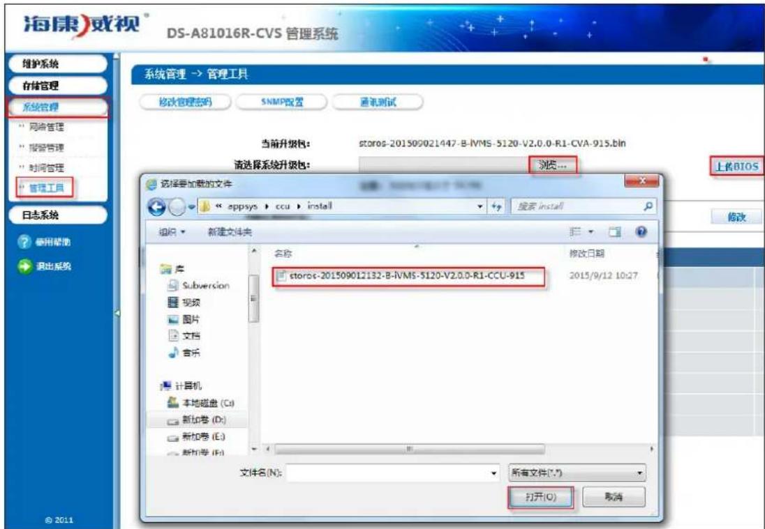
CCU is cloud storage calculate software. You should install the CVA when need the function of searching pictures by pictures or intelligent retrieval.
Installation steps are as follows:
Go to https://xx.xx.xx.xx:2004 (xx.xx.xx.xx is the storage server IP.) to join 'System -> Management Tool' interface. Choose storos-xxxxxxxxxxxx-B-iVMS-5120-V2.x.x-Sx-CCU-915.bin to upgrade and view the Operation
Log making sure it completed. Then you can run the CCU without restarting the server.
2.3 Management Node Deployment
2.3.1 Installation of Management Node Deployment System
Running CVMN node application server needs to install CentOS7 operation system. The specific method of installation and configuration is in ‘Enclosure 1: CentOS7 operating system installation manual’.
2.3.2 Installation of Management Node Software
Standard cloud is made up off two kinds of hardware configurations including management node CVMN and storage node CVSN. Standard cloud need to deploy centos7.0 system on the management node first. Then install corresponding software.
- Prepare a server to install CentOS7.
- Copy all installation files under 'install_all \ cvmn_all' to any contents on the server.
- Installation steps are as follows:
1) Modify all installation script permissions copied to make it perform the permission (chmod 755 *).
2) Perform installation script(./install.sh). Complete the installation according to the steps in installation script.
![[root@ha845 cvmn_all]# ./install.sh ********************************************************************** * ivMS-5120 install ********************************************************************** * please enter your choose:(1-4) * * (1) one click Install cluster all component * * (2) one click Install HA all component * * (3) optional install component * * (4) exit menu * ********************************************************************** please input 1-4 number:](/content/2026/05/950233/images/8fc179163f85fac4dbdefb94dcc97ddd4dbb669243c9819bbdeb1e2ae37abc90.jpg)
Figure 2.3.2-1 Installation Steps
Installation script instruction:
a) There are two methods of CVM installation: (1) Distributed cluster installation(2n+1 devices); (2) HA cluster installation(2 devices); (3) Installation for custom.
b) The character of host name is limited to [a-z],[A-Z],[0-9] and '-' and its length should be 3-15 characters. Note: The host name of standard cloud platform management node should be different.
c) One-Click setup.
If you select one-click setup of corresponding mode, the system will automatically perform one-click unload before installing script.
Now you can start to install after upload is complete. First it will prompt you change the host name or not. You can choose yes or no according to individual demand. If enter yes, the next step is enter new host name.
![[root@ha845 cvmn_all]# ./install.sh ********************************************************************** * ivMS-5120 install ********************************************************************** * please enter your choose:(1-4) * * (1) One click Install cluster all component * * (2) One click Install HA all component * * (3) optional install component * * (4) exit menu ********************************************************************** please input 1-4 number:2 uninstall success. will install ha... stop service you want change your hostname? please input (yes/no): yes Please input your new hostname : vmnode1 Local hostname change successfully, new hostname: vmnode1 install cluster program will start, please wait a moment.](/content/2026/05/950233/images/0a10d5a3725ac53382b28ef1dd250eab379a9ec51c1982fdb87d50ff307d8b1f.jpg)
Figure 2.3.2-2 Modify Host Name
Then cluster, CVM, CPM, WED and SNMP will perform installation automatically. Please wait patiently for its completion. You can see the prompt information.
d) Custom Installation
Perform installation script(. / install.sh). Choose '3' and go to custom installation shown below:
![[root@ha845 cvmn_all]# ./install.sh ********************************************************************** * ivMS-5120 install ********************************************************************** * please enter your choose:(1-4) * * (1) one click Install cluster all component * * (2) one click Install HA all component * * (3) optional install component * * (4) exit menu ********************************************************************** please input 1-4 number:3 ********************************************************************** * ivMS-5120 optional install menu ********************************************************************** * please enter your choose:(1-6) * * (1) Install cluster * * (2) Install cvm * * (3) Install cpm * * (4) Install web * * (5) Install snmp * * (6) exit menu ********************************************************************** please input 1-6 number:](/content/2026/05/950233/images/49fde2d049c470bbe72fc2057cabe8c82426e14738ffd1e0a570af0e23495582.jpg)
Figure 2.3.2-3 Custom Installation
➢ Options 1-5 are respectively the installation software packages of management node CVMN. Do not need to install the item (5) of SNMP packets if no operational projects.
It will prompt you to select installation cluster mode or HA mode when installing (1) cluster. Then you will be prompted whether to change the host name. You can choose according to yourself.
Complete the installation according to the 2 \~ 5 steps.
Note: Each management node need to install the software.
2.4 Standard Double Clouds Machine HA Formation
For the convenience of description, we will use CVM1 and CVM2 on behalf of the formation of HA cluster of 2 CVMN servers.
2.4.1 Bind Net Port
Go respectively into the CVMN-WEB pages of CVM1 the CVM2 and enter https://xx.xx.xx.xx:5120 (xx.xx.xx.xx is the storage server IP.) to join 'System -> Network Management' interface, as shown in figure 2.4.1-1.
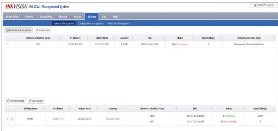
Figure 2.4.1-1 Net Port Binding
Do not need to bind network port if the device has only two data ports. Now you should set the eth1 as the heartbeat after cluster initialization. The information of Heartbeat configuration is in '3.4.3HA cluster heartbeat configuration'. Set the eth2 as the heartbeat and bind eht0 and eth1 if device has three or more than three data ports.
2.4.2 HA Cluster Formation and Initialization
The steps of HA cluster formation for two CVMN servers are as follows:
- Install the corresponding software for each server, with reference to the 3.3 management node (CVMN) deployment. Note: Select HA mode for installation.
- Choose one of the 2 servers, such as CVM1. Go to the CVMN-WEB page of CVM1. Enter https://xx.xx.xx.xx:5120 (xx.xx.xx.xx is the storage server IP.).
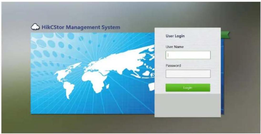
Figure 2.4.1-1 CVMN-WEB Login Screen
- Go to the welcome interface after login. Home page shows the current cluster profile. The initial state of the
cluster system is shown as 'no set-up'.
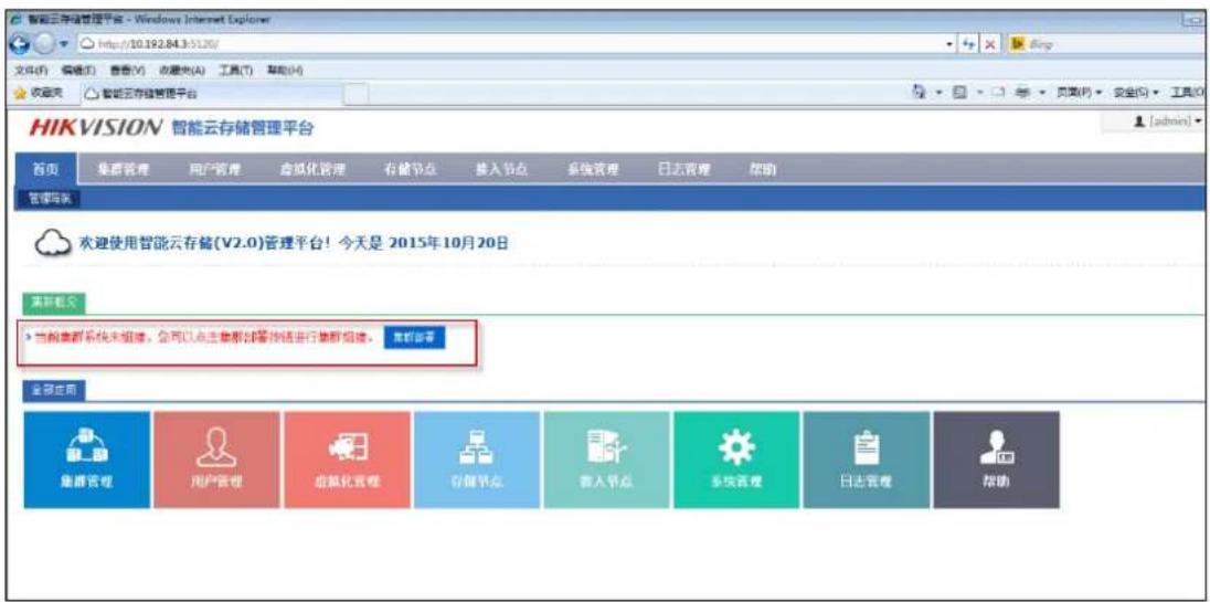
Click ‘Cluster Deployment’ in the page and it will pop up a mode selection window such as the figure 3.4.1-3. Select the deployment mode in accordance with the actual situation (in this case, select ‘Standard Cloud Deployment’). Then enter ‘Standard Cloud Deployment – Mode Selection’ to join configuration guide page.
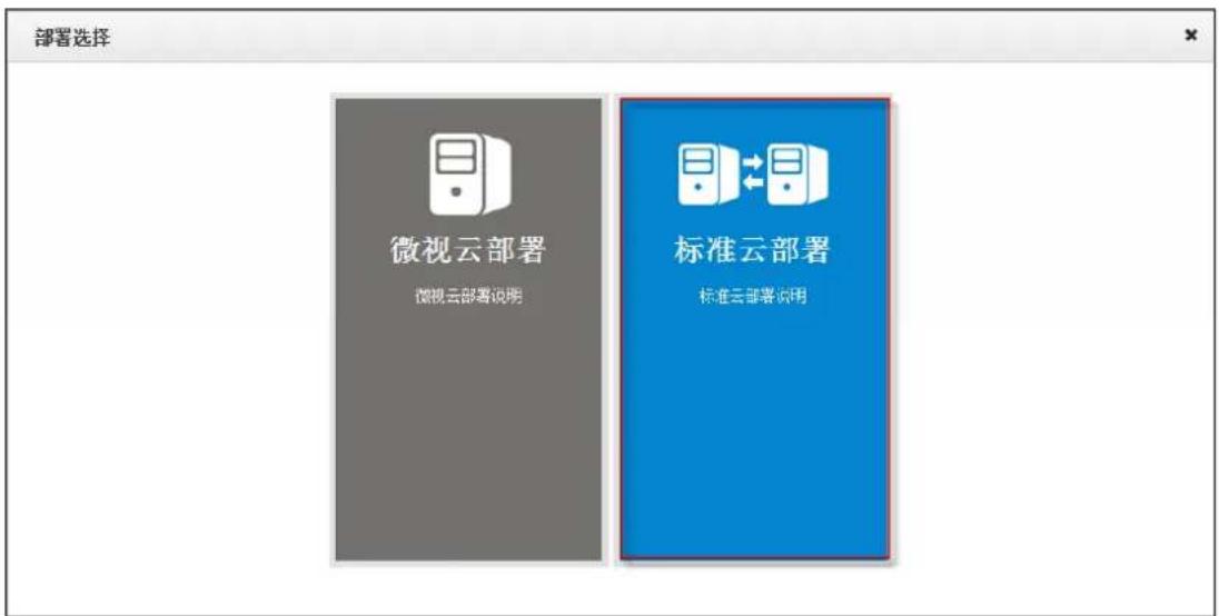
Click the button ‘Standard Cloud Deployment’ in the page and it will pop up a mode selection window such as the figure 3.4.1-4. Select the formation mode in accordance with the actual situation (in this case, select ‘HA Mode’). Then enter ‘Standard Cloud Deployment – HA Mode’ to join configuration guide page.
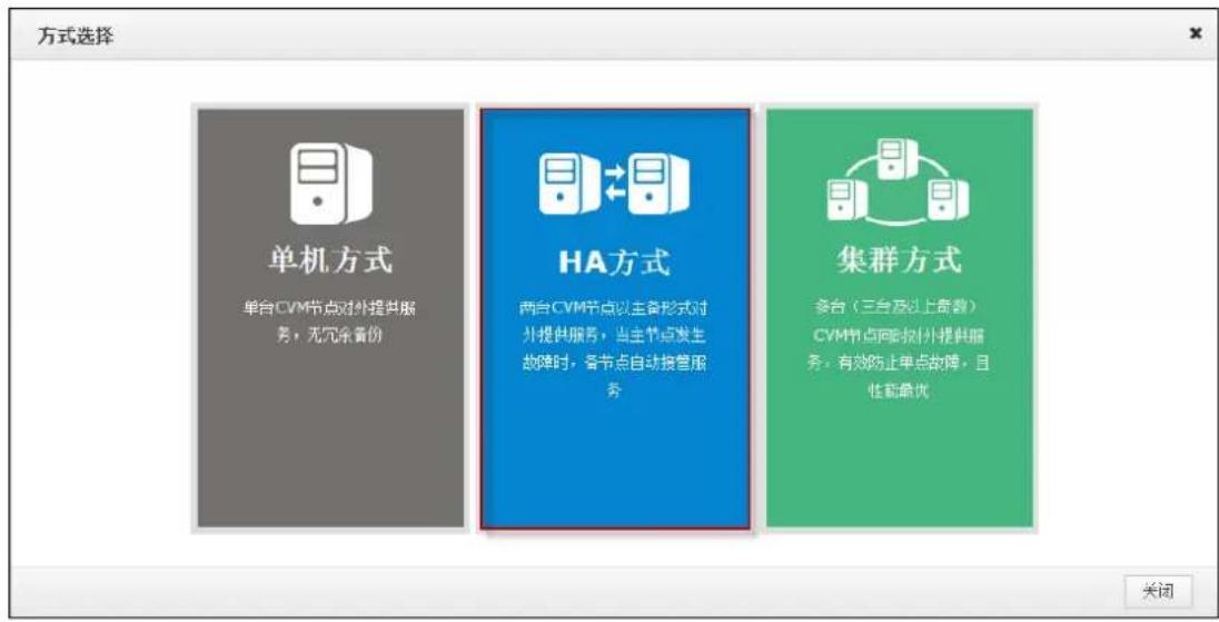
- First step of cluster configuration: Select Node. Enter the IP of CVM2 in the text box of 'Please enter the node IP'. Click 'Detection and Add' to join the CVM2 management node into the cluster.
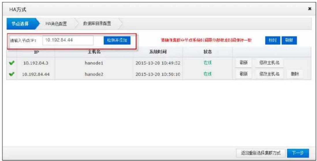
Perform the time calibration first after the node addition to ensure that the time of the cluster server is consistent with the external standard time. Click the 'Time Calibration' to adjust the machine time, and then click 'OK' to complete the calibration.
If you want to modify the host name of the CVMN machine, click the button in this page, enter 'new host name' in the pop-up window (shown in Figure 3.4.1-6). Click 'OK' to complete the modification. Note: Each host should have different name.
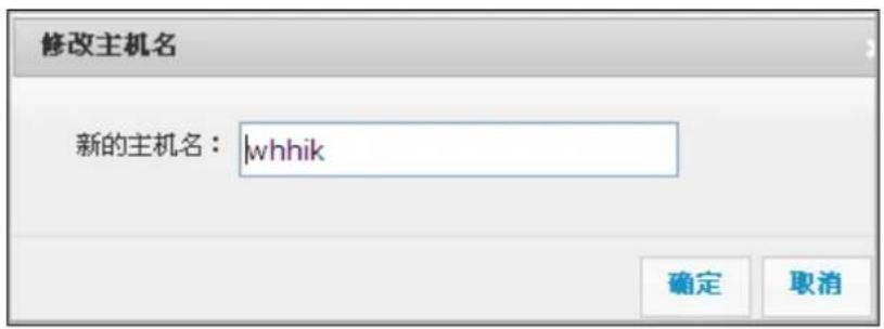
Click 'Next Step' to jump to the next step of cluster configuration after modification.
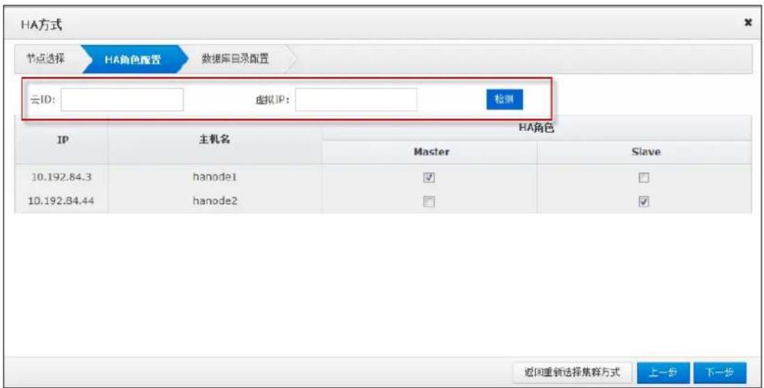
- Second step of cluster configuration: HA role configuration. The HA cluster need a virtual IP as the only interface for external service (Virtual IP must be segment and not using. You can test it if available through the button 'Test'). Enter a custom HA cluster ID in 'Cloud ID' text box and specify the role of HA (by default). Then click 'next'.
- Third step of cluster configuration: Database directory configuration. This section is mainly to configure the data index directory and data directory. You the better create different disks if you need to configure a number of data directories.
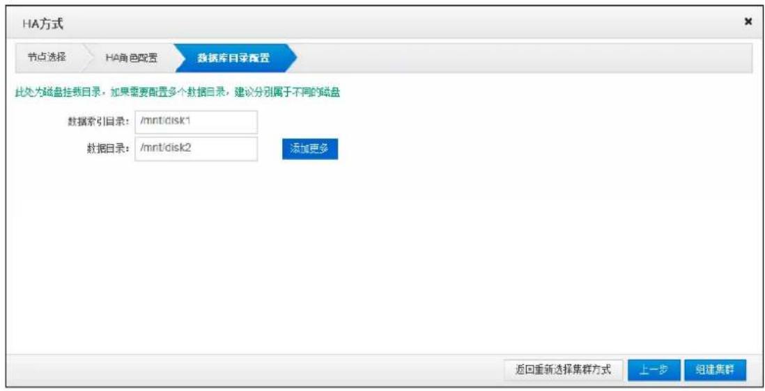
- Now you have completed all the preparations for the work of cluster formation. You can click the 'Last Step' if you want to go back again. Click 'Return to Select Cluster Mode' to reselect and install the cluster mode if you want to modify the formation of cluster mode. Otherwise, click 'Set up the Cluster' and it will pop up a confirmation box as shown in figure 2.4.1-9.
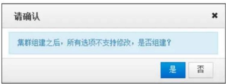
- Choose 'yes' to start cluster formation and it will automatically initialize and wait for the completion of the initialization.
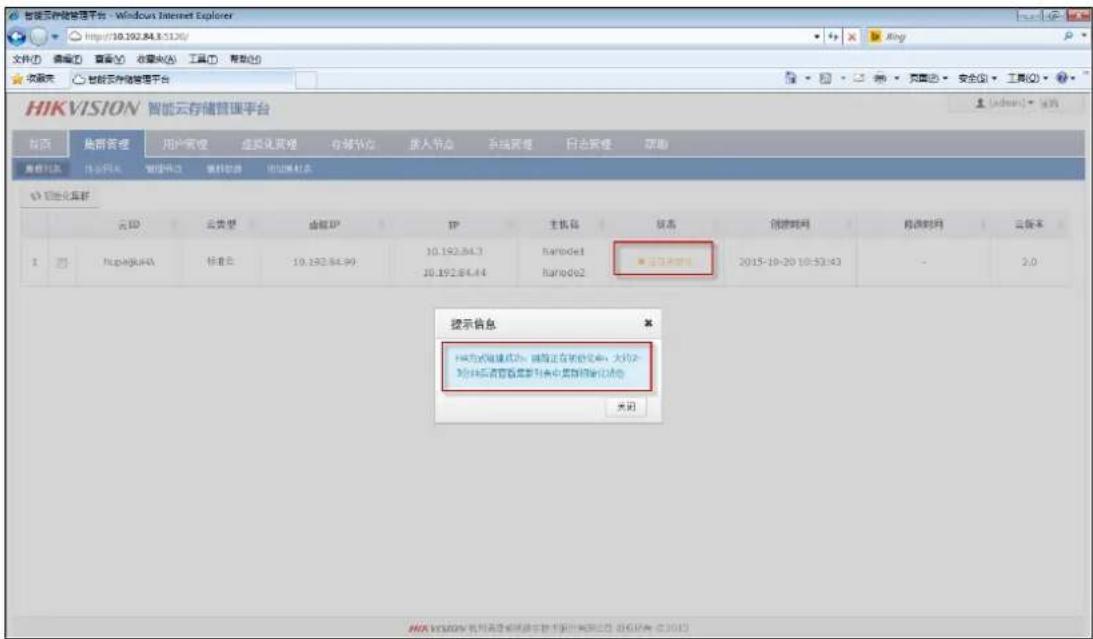
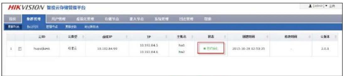
The cluster state is displayed as ‘being initialized’ in the initialization process. Wait for 2-3 minutes. Refresh the page manually. If the cluster state shows ‘initialized’, it has been initialized successfully.
- Connect eth1 network ports of CVM1 and CVM2 servers with one cable.
- Visit the CVMN-WEB page of CVM1. Enter the 'System - Network Management' interface shown in figure 2.4.3-1.
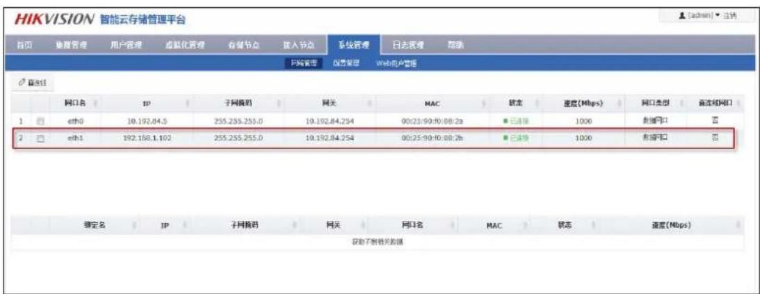
Check eth1 and click 'Straight-Through'. Select 'yes' in the pop-up confirmation box. Wait for the prompt of success and you can see the 'direct connection' of eth1 displaying 'Yes'.
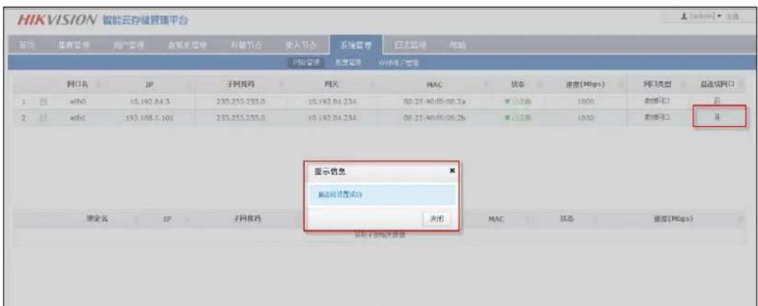
- Visit the CVMN-WEB page of CVM2 to finish the direct connection configuration. The cluster can begin to provide services to external normally after configuration completed.
2.5 Establish Standard Cloud Cluster
To achieve a clear description, the CVMN servers below for establishing cluster are hereinafter referred to as CVM1, CVM2 and CVM2 respectively.
2.5.1 Bind Network Interface
Go to CVMN-WEB page of CVM1 and CVM2 respectively by visiting http:// xx.xx.xx.xx:5120 (xx.xx.xx.xx refers to the management server IP)--->Login-->System-->Network
Management-->Tick eth0 and eth1-->Click Bind Network Interfaces. Please see Figure 2.5.1-1
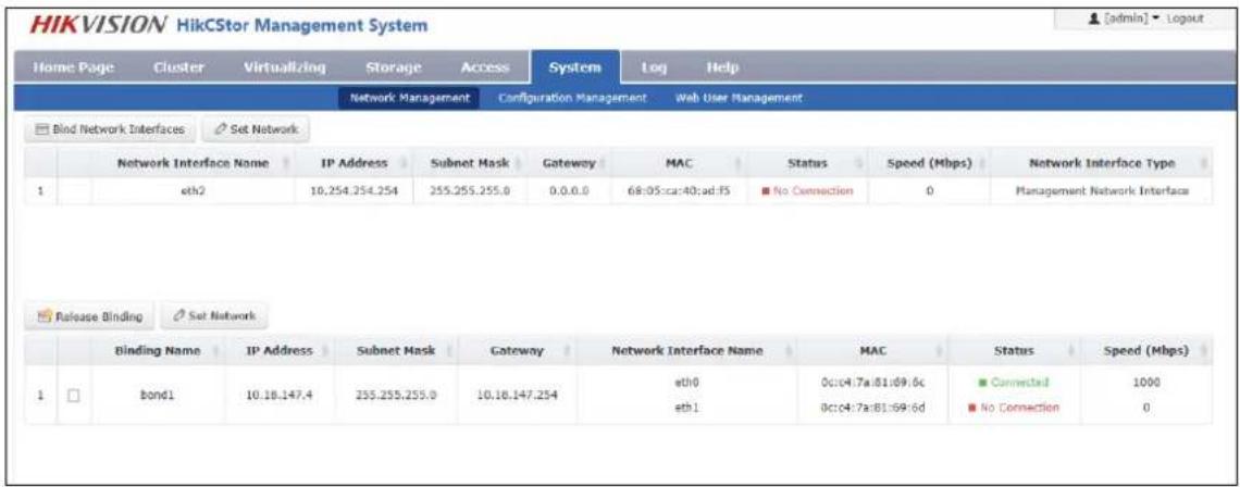
Figure 2.5.1-1 Bind Network Interface
2.5.2 Establish & Initialize Standard Cloud Cluster
Steps of cluster establishment on CVM1, CVM2 and CVM3 are as below:
- Install the software on each server. Note: please select cluster mode when installing. Please refer to Section 2.3-CVMN Deployment.
- Select one server from CVM1, CVM2 and CVM3 optionally. Taking CVM1 for an example, go to CVMN-WEB page of CVM1 by visiting http:// xx.xx.xx.xx:5120 (xx.xx.xx.xx refers to the management server IP).
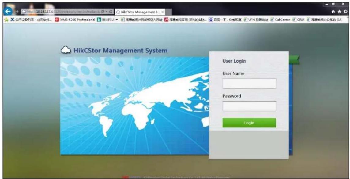
Figure 2.5.2-1 CVMN-WEB Login Interface
- After login, homepage is displayed which contains a cluster description. The original state indicates cluster system unestablished.
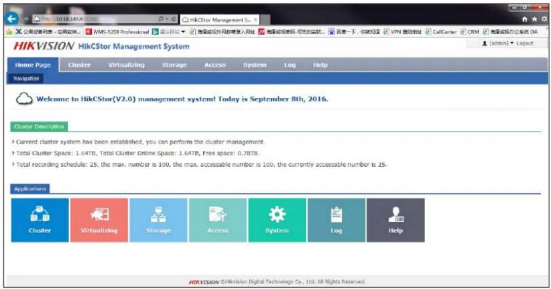
Figure 2.5.2-2 Cluster Description
Click Deploy Cluster-->Select one cloud type in the pop-up window (For example, Standard Cloud Deployment is selected in this text)-->Select one deployment approach optionally (For example, Cluster is selected in this text).
- Step 1 for cluster establishment: node selection.
Input CVM2 IP address in “Please Input Node IP” box-->Click Detect & Add to add CVM2 to the cluster. Likewise, add CVM3 to the cluster.
Having completed adding CVMN to the cluster, please execute time synchronization operation to ensure server time and standard time consistent. Click Synchronization to adjust server time. Then click OK to finish the operation.
To modify host name of CVMN, if needed, click Modify Host Name-->Input new host name in pop-up window-->Click OK to finish modification. Note: host name of each CVMN must be unique.
Click Next to enter load balancing configuration page.
- Step 2 for cluster establishment: load balancing configuration.
CVMN cluster requires a virtual IP to serve as the only port for external service (The virtual IP must
be available in the same network segment with CVMN)--->Click Check to see whether the IP is available-->Assign roles for load balancing (Keep default value)-->Click Next.
- Step 3 for cluster establishment: database role configuration.
Configure the database role as follows:
- Cloud ID: input the cluster ID
- Maximum Database Cache: RAM allocated to the database. If the physical memory of the server is less than 32G, it is suggested to input 1024; if the physical memory is no less than 32G, it is suggested to input 4096.
- Check distributed database role (Keep default value)
Having completed the configuration above, please click Next.
- Step 3 for cluster establishment: database directory configuration
In this step, configure database index directory, database log directory and data directory. If more than one data directory needs to be configured, it is suggested to allocate them to different disk. It is recommended to keep default value here.
- Till now, all configurations for cluster establishment have been finished.
To change values configured at the previous step, please click Back; to change cluster approach, please click Back to Cluster Approach Selection; to finish cluster establishing configuration, please click Establish Cluster.
- When the cluster is established, it will be initialized automatically.
During the initializing process, the cluster status indicates “initializing”. Two or three minutes later, refresh the page. The status indicates “initialized” which means the cluster has been initialized and is ready to perform its service.
![HIKVISION HikCStor Management System [admin] - Layout Home Page Cluster Virtualizing Storage Access System Log Help Cluster List CVM Cluster Parameters Address Mapping List + Expand Cluster Cloud ID Cloud Type Virtual IP Address IP Address Serial No. Status Created Time Modification Time Cloud Version 1 5200-Test Micro Video Cloud - 10.18.147.4 000C407A0B106906C ● Initiated 2016-07-15 12:57:55 2016-08-03 16:10:18 2.1.0](/content/2026/05/950233/images/33975b14c6db4ff69183d2a355044b00fa3f1c6508de193a156248f62bd49fe3.jpg)
Figure 2.5.2-3 Cluster Initialized
2.6 Configure Standard Cloud
When a standard cloud cluster is established, it can be used after customized configuration.
2.6.1 Configure CVS
Go to CVSN-WEB page by visiting http://xx.xx.xx.xx:5119 (xx.xx.xx.xx refers to CVS IP address)->Login-->System-->Configuration Management-->Check whether CVS status indicates ON-->Input the cluster virtual IP in CVM IP box-->Click Set CVS Parameters.
After completing the configuration above, CVS service will reboot automatically. Please wait until the reboot is completed.
Go to CVMN-WEB page by visiting http://xx.xx.xx.xx:5120 (xx.xx.xx.xx refers to Cluster Virtual IP address)-->Login-->Storage-->CVS-->Check the CVS information.
2.6.2 Create Domain
When establishing a Standard Cloud, domain is not created by default. Users are allowed to create independent domains optionally. When a domain has been created, users can add one or more CVS to it. The space of a domain depends on that of all CVS added to it: more than one resource pool can be created in a domain; the minimum domain includes only one CVS.
Go to CVMN-WEB page by visiting http://xx.xx.xx.xx:5120 (xx.xx.xx.xx refers to Cluster Virtual IP
address)->Login->Virtualizing->Domain Management--> Click Create Domain-->Input domain name and description-->Click OK to finish creating domain. Please see Figure 2.6.2-1.
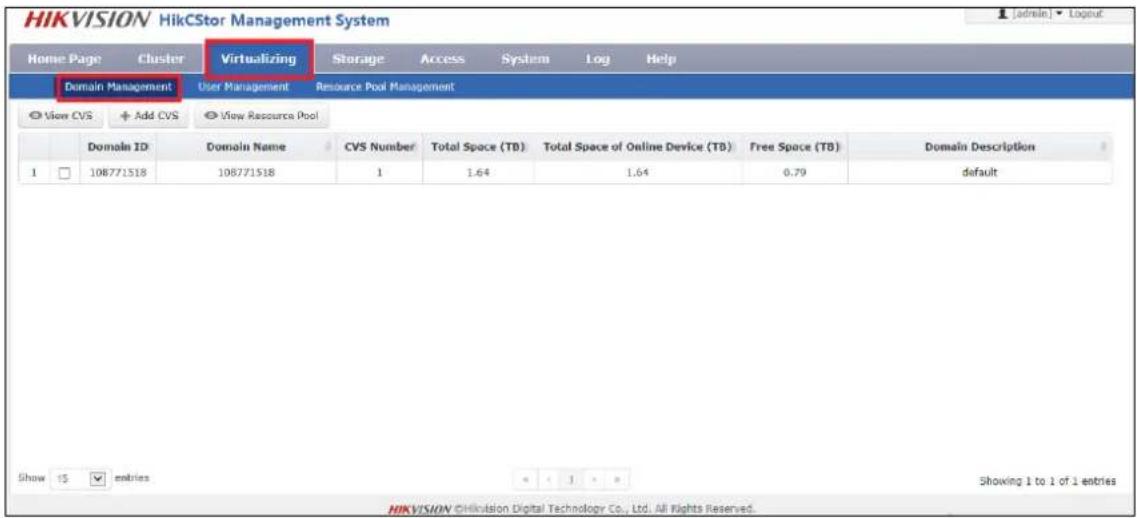
Figure 2.6.2-1 Create Domain
2.6.3 Modify Domain
To modify a domain that has been created, if needed, administrator is allowed to manually modify its information. If not needed, please skip this section.
Go to CVMN-WEB page by visiting http://xx.xx.xx.xx:5120 (xx.xx.xx.xx refers to Cluster Virtual IP address)-->Login-->Virtualizing-->Domain Management-->Tick the domain-->Click Modify Domain-->Input new domain name and description in the pop-up window. Note: as domain ID is automatically created by the system, it can't be modified manually.
2.6.4 Add CVS to Domain
Each domain contains one or more CVS which can't be added to other domains. CVS is available for cluster use only when it has been added to a domain.
Go to CVMN-WEB page by visiting http://xx.xx.xx.xx:5120 (xx.xx.xx.xx refers to Cluster Virtual IP address)-->Login-->Virtualizing-->Domain Management-->Tick the domain to which the CVS is to be added-->Click Add CVS-->Tick the CVS to be added-->Click OK. Please see Figure 2.6.4-1.
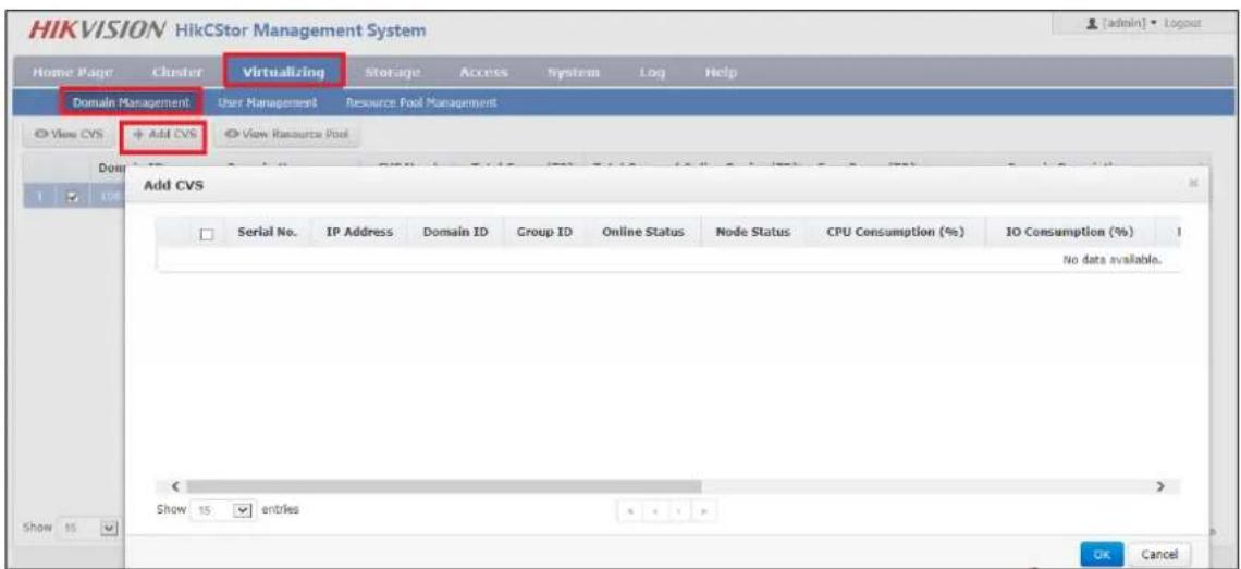
Figure 2.6.4-1 Add CVS
2.6.5 Create Resource Pool
HikCStor Management System achieves centralized management of all CVS in the cluster by integrating them in one or more virtual resource pools. Administrator is allowed to create resource pools optionally in a domain. When creating a resource pool, administrator needs to allocate certain storage capacity to it. Specific steps are as below:
Go to CVMN-WEB page by visiting http://xx.xx.xx.xx:5120 (xx.xx.xx.xx refers to Cluster Virtual IP address)-->Login-->Virtualizing-->Resource Pool Management-->Create Resource Pool. Please see Figure 2.6.5-1
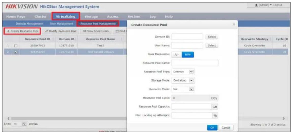
Figure 2.6.5-1 Create Resource Pool
In the pop-up window, configure the following items:
- Domain ID: select one domain in which the resource pool is to be created.
- User Name: Select a bond user. If a resource pool is bonded to a user, the user will have its read-and-write permission; if not bonded to any user, only default user of the system has its read-and-write permission.
- Resource Pool Name: name the resource pool optionally, supporting a combination of number, letter, strikethrough and underline, which can't begin with “-”.
- Resource Pool Type: Common (for video, SureStream and picture storage)/Video (for video and SureStream storage)/Picture (for picture storage only).
● Storage Mode: Centralized/Dispersed. - Overwrite Mode: Not (not overwriting)/Capacity (starting overwriting from the earliest time point when the resource pool capacity is fully occupied)/Cycle (deleting overdue data when the resource pool completes its preset cycle)
- Resource Pool Cycle: overwriting resource pool after every other preset cycle. Input number optionally. Unit: day.
● Resource Pool Capacity: capacity of a resource pool. Unit: GB.
● Max. Locking up Attempts: maximum space for locking up in a resource pool. - Transcoding Type: Not/Frame (transcoding frame for storage automatically at the end of a cycle). When Frame is selected as transcoding type, original data cycle needs to be set as well. In this way, the resource pool will store original data within the cycle only, while data before the cycle will be transcoded for storage.
Having finished the above configuration, please click OK and a new resource pool is created.
2.6.6 Modify Resource Pool
To modify a resource pool that has been created, if needed, administrator is allowed to manually modify its information. If not needed, please skip this section.
Go to CVMN-WEB page by visiting http://xx.xx.xx.xx:5120 (xx.xx.xx.xx refers to Cluster Virtual IP address)-->Login-->Virtualizing-->Resource Pool Management-->Tick the resource pool-->Click Modify Resource Pool-->modify the information in the pop-up window. Please see Figure 2.6.6-1.
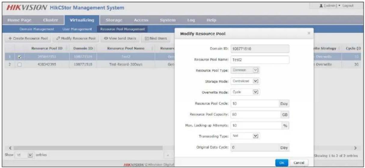
Figure 2.6.6-1 Modify Resource Pool
- Domain ID: not support modifying.
● Resource Pool Name: support inputting a new name.
● Resource Pool Type: not support modifying.
● Storage Mode: support changing the storage mode to Centralized or Dispersed.
● Overwrite Mode: support changing the overwrite mode to Not, Capacity or Cycle.
● Resource Pool Cycle: support modifying the cycle duration. Unit: day.
● Resource Pool Capacity: support expanding or shrinking capacity.
● Max. Locking up Attempts: support modifying space for locking up data.
- For the resource pool in which Cycle is selected as overwrite mode, transcoding type and original data cycle can be modified; for other resource pools in which Not or Capacity is selected as overwrite mode, transcoding type can't be selected or modified.
Note: shrinking resource pool capacity may leads to overwriting history data earlier than the preset
date.
2.6.7 Configure CVA
For picture project in which CVA software is not installed, this section can be skipped.
For video project in which CVA software is installed, the following configuration needs to be done.
Go to CVSN-WEB page by visiting http://xx.xx.xx.xx:5119 (xx.xx.xx.xx refers to CVS IP address)--->Login-->Access-->Configuration Management-->Input the cluster virtual IP in CVM IP and CPM IP boxes-->Click Set CVA Parameter-->Pop up configuration succeeded hint
Go to CVMN-WEB page by visiting http://xx.xx.xx.xx:5120 (xx.xx.xx.xx refers to Cluster Virtual IP address)-->Login-->Access-->CVA-->Check Cluster Status.
2.6.8 Add CVA to Cluster
For picture project in which CVA software is not installed, this section can be skipped.
For video project, CVA needs to join the CVMN management cluster before receiving recording schedule from the cluster.
Go to CVMN-WEB page by visiting http://xx.xx.xx.xx:5120 (xx.xx.xx.xx refers to Cluster Virtual IP address)-->Login-->Access-->CVA-->Check all CVA under the management of current cluster. In this page, you can check Serial No., IP Address, Name, Node Status, Cluster Status, CPU Consumption, Memory Consumption, Network (in/out), Maximum Live View Connection Number, Current Live View Connection Number, Maximum Playback Connection Number, Current Playback Connection Number, etc. Maximum Connection Number refers to maximum number of monitoring spot that VA can manage; Current Connection Number refers to current number of monitoring spot that VA manages.
Go to CVMN-WEB page by visiting http://xx.xx.xx.xx:5120 (xx.xx.xx.xx refers to Cluster Virtual IP address)-->Login-->Access-->CVA-->Tick the VA node-->Click Join Cluster-->Input connection number optionally-->Click OK. Likewise, configure other VA nodes. Please see Figure 2.6.8-1
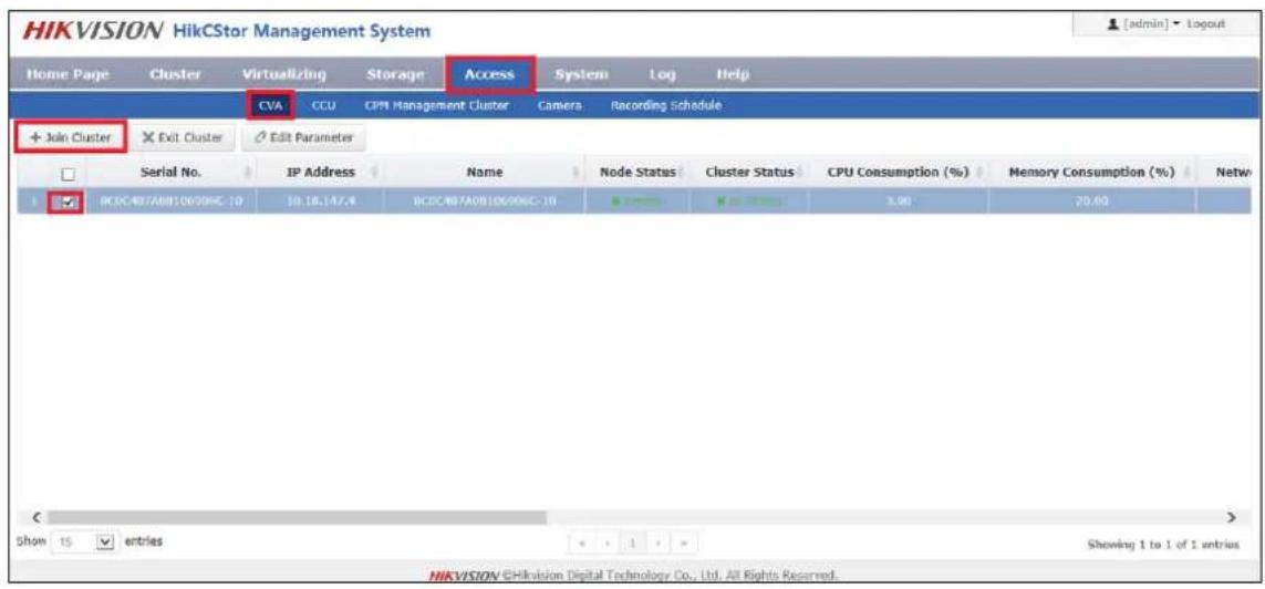
Figure 2.6.8-1 Add CVA to Cluster
2.6.9 Modify CVA Parameter
To modify a CVA that has joined to cluster, if needed, administrator is allowed to manually modify its parameters. If not needed, please skip this section.
Go to CVMN-WEB page by visiting http://xx.xx.xx.xx:5120 (xx.xx.xx.xx refers to Cluster Virtual IP address)-->Login-->Access-->CVA-->Tick the node to be modified-->Click Edit Parameter-->Modify Node Name, Maximum Live View Connection Number and Maximum Playback Connection Number in the pop-up window. Please see Figure2.6.9-1.
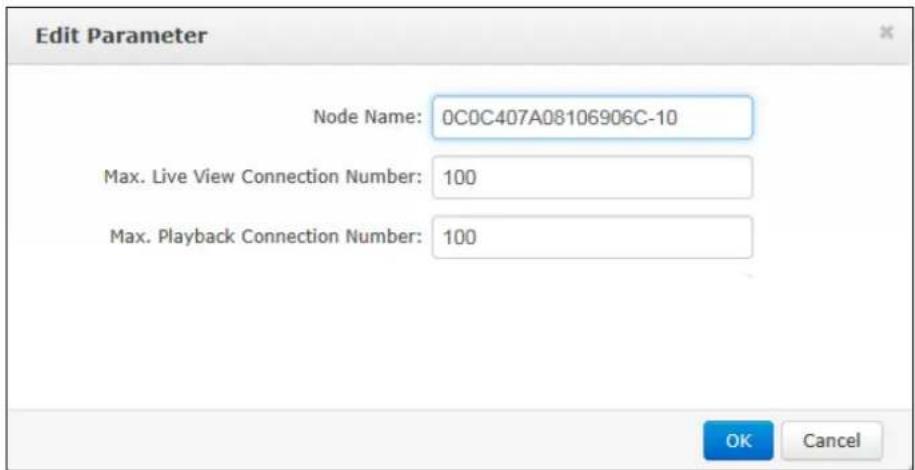
Figure2.6.9-1 Edit Parameter
2.6.10 Configure CCU
For the project without requirement of searching picture by picture or intelligent retrieval function, CCU software is not installed. This section can be skipped.
For the project in which CCU software is installed, the following configuration needs to be done.
Go to CVSN-WEB page by visiting http://xx.xx.xx.xx:5120 (xx.xx.xx.xx refers to CVS IP address)-->Login-->Access-->Configuration Management-->Input the cluster virtual IP in CPM IP box-->Click Set CCU Parameter-->Pop up configuration succeeded hint
Having finished the configuration above, go to CVMN-WEB page by visiting
http://xx.xx.xx.xx:5120 (xx.xx.xx.xx refers to Cluster Virtual IP
address)-->Login-->Access-->CCU-->Check CCU status.
CCU is available for use when it has been added to the cluster. No further configuration needs to be done.
2.6.11 Configure Synchronization Server
For project of active video storage, synchronization server must be configured on HikCStor Management System.
For project of passive video or picture storage, synchronization server does not have to be configured on HikCStor Management System.
Go to CVMN-WEB page by visiting http://xx.xx.xx.xx:5120 (xx.xx.xx.xx refers to Cluster Virtual IP address)-->Login-->Cluster-->Cluster Parameters-->Input synchronization server IP and configure synchronization interval (in general case, keep the default value:1440)-->Click Set Cluster Parameters-->Pop up configuration succeeded hint. Please see Figure 2.6.11-1.
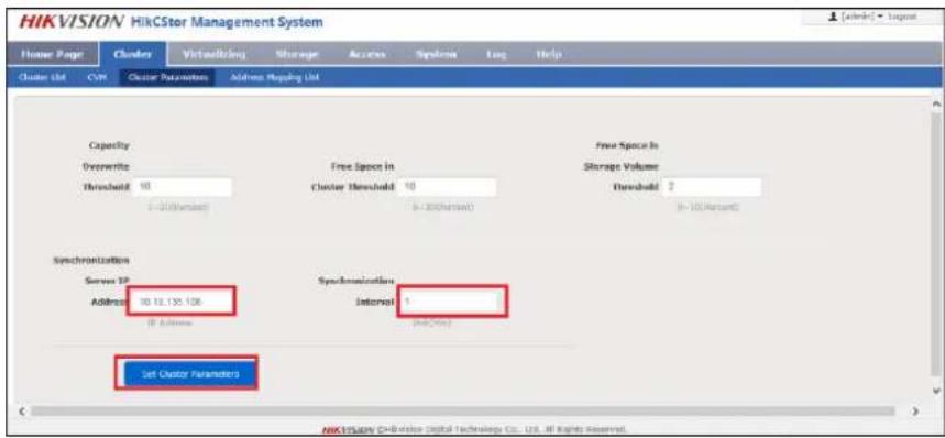
Figure 2.6.11-1 Set Cluster Parameters
Go to each CVS management system by visiting https://xx.xx.xx.xx:2004 (xx.xx.xx.xx refers to CVS IP address)-->Login--Log-->Operation Log-->Check log detail. “Synchronization Server: xx.xx.xx.xx Succeeded” indicates synchronization has succeeded.
2.6.12 Configure Group IP
CVS that has been added to a domain can be grouped optionally; while CVS that has not been added to any domain is divided into one group by default. Group is linked to CVS only, without any linkage to resource pool. When allocating resources, groups are viewable for users. The purpose of grouping is to avoid series flow among switches while recording.
For users who have the requirements of grouping CVS, please follow the configuration steps in this section. For users who don't have such requirements, please skip this section.
Go to CVMN-WEB page by visiting http://xx.xx.xx.xx:5120 (xx.xx.xx.xx refers to Cluster Virtual IP address)-->Login-->Virtualizing-->Group Management-->Download Template--> Input information in the template by following the format: Group ID-CVS IP. For example, CVS are divided into three groups in Figure 2.6.12-1.
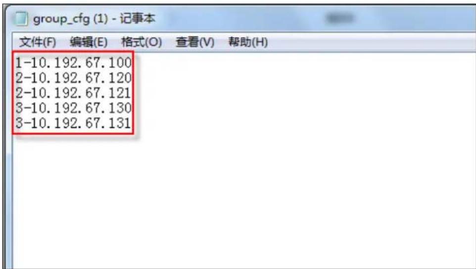
Figure 2.6.12-1 Group Template
Click Virtualizing-->Group Management-->Click Configure Group ID-->Tick the domain in which group ID needs to be configured-->Click OK-->Click Browse in the pop-up window-->Select the group template you have configured-->Click OK.
Having completed grouping, group IP list will be displayed. Click Storage-->CVS-->Check group ID of the CVS.
2.6.13 Resource Pool User Management
HikCStor Management System has only one user with super administrator permission by default that has read-and-write permission for all resource pools. When connecting with professional platform, default user is available for use. For any particular requirements, if needed, the System also provides resource pool user management function which can create particular user to connect with the platform.
More than one user can be created. Every user must bind one or more resource pools; every resource pool can be bonded by more than one users. The relationship between user and resource pool is many-to-many. When a user has bounded a resource pool, the user has its read-and-write permission.
For the case where professional platform is only connected with the default user, this section can be skipped.
For the case where particular resource pool user needs to be created, please follow the configuration steps below.
1. Create User
Go to CVMN-WEB page by visiting http://xx.xx.xx.xx:5120 (xx.xx.xx.xx refers to Cluster Virtual IP address)-->Login-->Virtualizing-->User Management-->Click Create User-->Input user information optionally in the pop-up window. Please see Figure 2.6.13-1
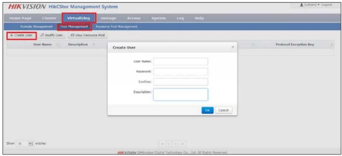
Figure 2.6.13-1 Create User
Configure the following items in the pop-up window.
- User Name: can't be same with other user names. Number, letter, strikethrough and underline are supported.
- Password: for login the system.
● Security Question & Answer/Description
Having completed the configuration, click Ok. A new user will be created.
2. Modify User
For the user that has been created, administrator is allowed to modify its information manually.
Go to CVMN-WEB page by visiting http://xx.xx.xx.xx:5120 (xx.xx.xx.xx refers to Cluster Virtual IP
address)-->Login-->Virtualizing-->User Management-->Tick the user to be modified-->Click Modify User-->Modify the description in the pop-up window.
3. Bind User to Resource Pool
When a user has been created, bind it to resource pool optionally. In this way, the user will have read-and-write permission of the resource pool. Specific operation steps are as below.
Go to CVMN-WEB page by visiting http://xx.xx.xx.xx:5120 (xx.xx.xx.xx refers to Cluster Virtual IP address)--->Login-->Virtualizing-->Resource Pool Management-->Click Bind Users-->Select user(s) to be bonded-->Click OK. Please see Figure 2.6.13-2
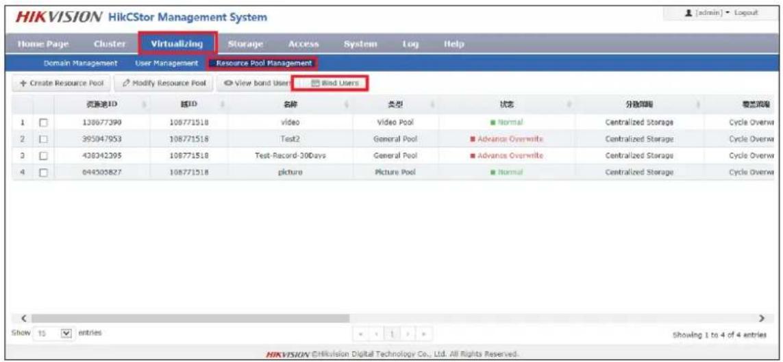
Figure 2.6.13-2 Bind Users
2.6.14 Manage Bucket
Bucket needs to be created before storing the Object file. For the project without the requirement of file storage, this section can be skipped. For the project with such a requirement, please follow the configuration steps as below.
As Bucket is created to store Object file, users are allowed to create one or more buckets optionally. Every Bucket name must be unique in the System. Every user can have up to 10 buckets by default. If more buckets per user are required, please ask Hikvision Technical Support Engineers to modify configuration. One bucket can't nest another bucket.
As any Bucket operation is centralized, it's not suggested to create or delete bucket frequently.
Bucket name must be encoded by utf-8 and follow the rules below.
1) A combination of small letter, number and underline
2) Start with number or small letter
3) No less than 3 bytes and no more than 64 bytes
4) Bucket cannot begin with the word HikCStor (HikCStor may be an internal sign for Hikvision Cloud Storage)
HikCStor currently supports the following permissions:
1) Read-and-write: all users
2) Read Only: Bucket owner has read-and-write permission, while other users can only have read permission.
3) Private: only Bucket owner has read-and-write permission.
1. Create Bucket
Go to CVMN-WEB page by visiting http://xx.xx.xx.xx:5120 (xx.xx.xx.xx refers to Cluster Virtual IP address)-->Login-->Virtualizing-->Bucket Management-->Click Create Bucket-->Input information optionally in the pop-up window.
Parameter description:
Bucket Name: unique in HikCStor Management System
User Name: Select one resource pool user to make it the owner of the bucket.
Bucket Storage Cycle: “-1” indicates Object files in the bucket never expire. A round number is allowed to input. Unit: day. The storage cycle begins to count when the object is stored in the System. When reaching the end of the cycle, the System will automatically delete overdue Object in the bucket.
Storage Location: must keep default value LOCAL-1
2. Query Bucket Information
When a Bucket has been created, you can check bucket information of the user you query. Bucket information includes: Bucket Name, Capacity, Remaining Capacity, Storage Location, Permission, Cycle, and Create Time.
Go to CVMN-WEB page by visiting http://xx.xx.xx.xx:5120 (xx.xx.xx.xx refers to Cluster Virtual IP address)-->Login-->Virtualizing-->Bucket Management-->Input user name-->Click Query to check bucket information owned by the user.
3. Modify Bucket
HikCStor Management System supports modifying Buck permission, storage cycle and capacity.
Go to CVMN-WEB page by visiting http://xx.xx.xx.xx:5120 (xx.xx.xx.xx refers to Cluster Virtual IP address)-->Login-->Virtualizing-->Bucket Management-->Click Modify Bucket-->Modify certain items in the pop-up window-->Click OK to finish modification.
3 Video Storage Configuration
3.1 Video Storage Configuration of the Public Security Platform
The chapter only introduces the steps of configuring the recording schedule to the cloud storage in the public security platform. Please refer to the installation of the public security platform and other configurations in this platform.
3.1.1 Add Server
Add the corresponding servers in the platform before the cloud storage joins to the public security platform.
Login the web page of the public security platform and enter the home page as follows:
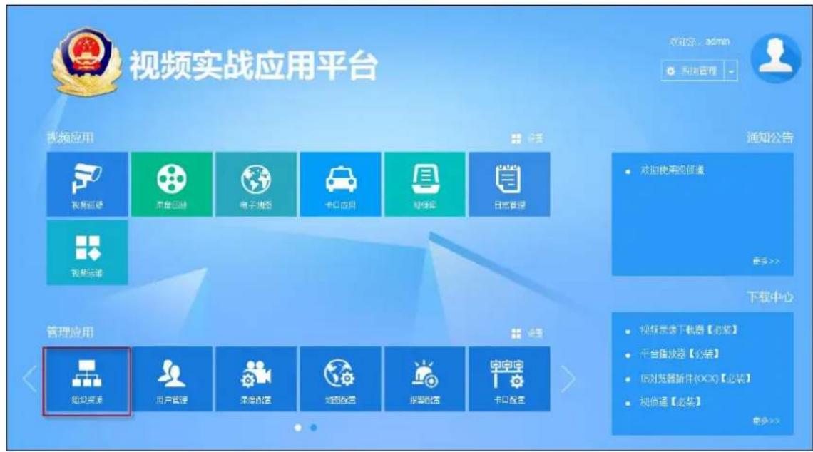
Fig. 3.2.1-1 Home page of the public security platform
1. Add Video Record Management (VRM)
Click the 'Organizational Resource' on the home page and enter the Organizational Resource page. Click 'server' and enter server tab page. Click 添加 button, select 'Video Record Management (VRM)' as follows:
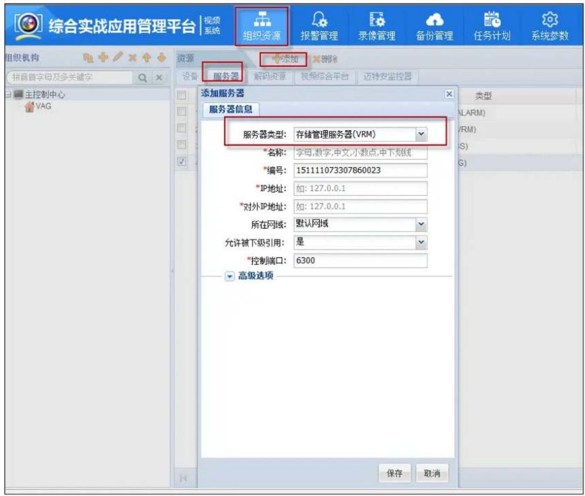
Number: generated by default or modified manually
IP address: IP address of installing VRM server is generally that of the installing platform software
External IP address: external IP address of the VRM server is generally consistent with the 'IP address'
2. Add Cloud Storage Server (CSS)
Click 'server' and enter the server tab page. Click 添加 button and select 'Cloud Storage Server', the configuration as follows
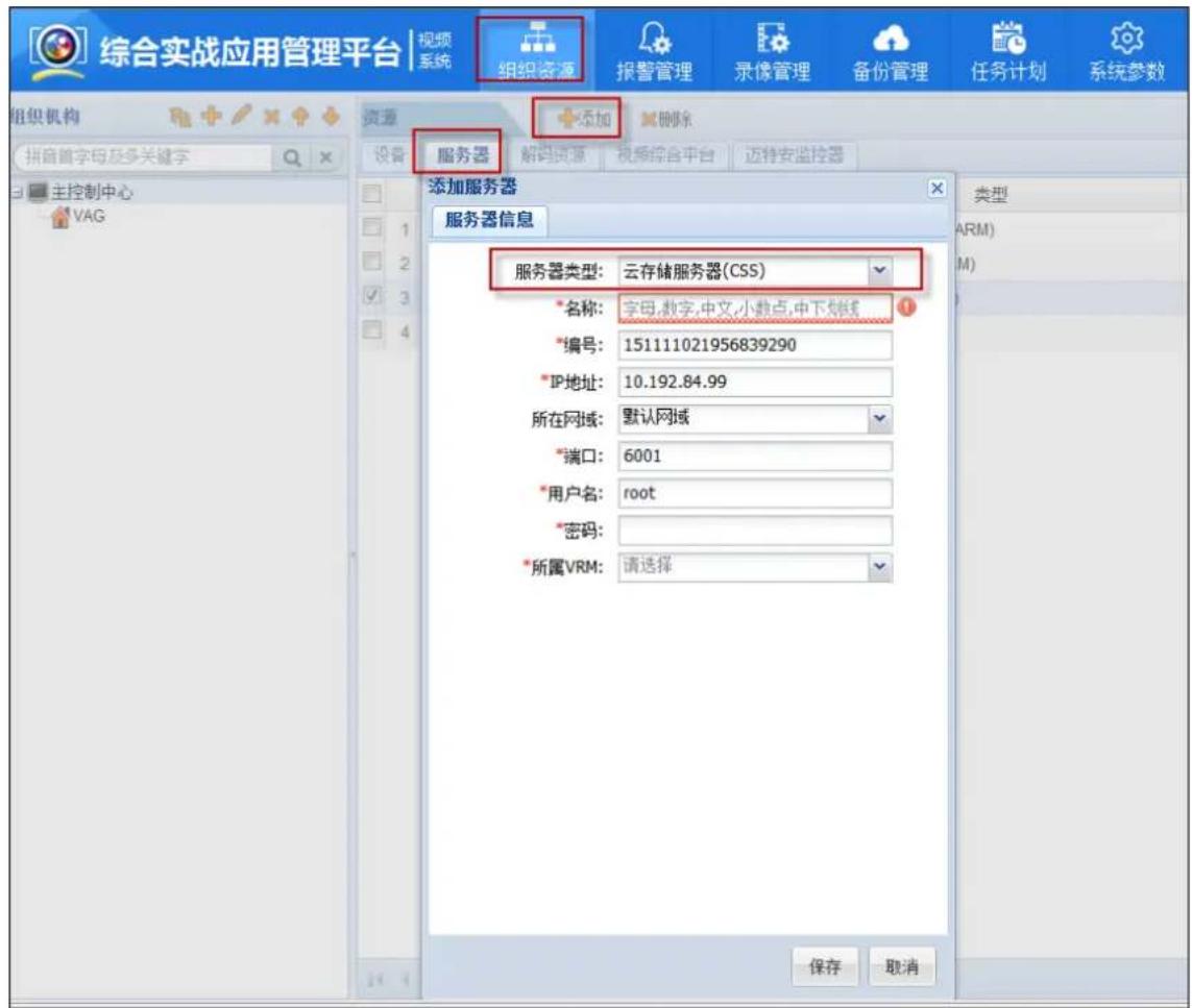
Number: generated by default or modified manually
IP address: virtual IP of the Cloud Storage Cluster
Port: external server port of the cloud storage is 6021 which is docking the smart cloud storage; consult the technical support of the cloud storage about the specific
User name: cloud storage user
Password: the password of the cloud storage, consult the technical support of the cloud
storage about the specific
VRM: select the added VRM server of the last chapter
3. Add Video Access Gateway(VAG)
Click 'server' and enter the server tab page. Click 添加 button and select 'Video Access Gateway (VAG) ',the configuration as follows:
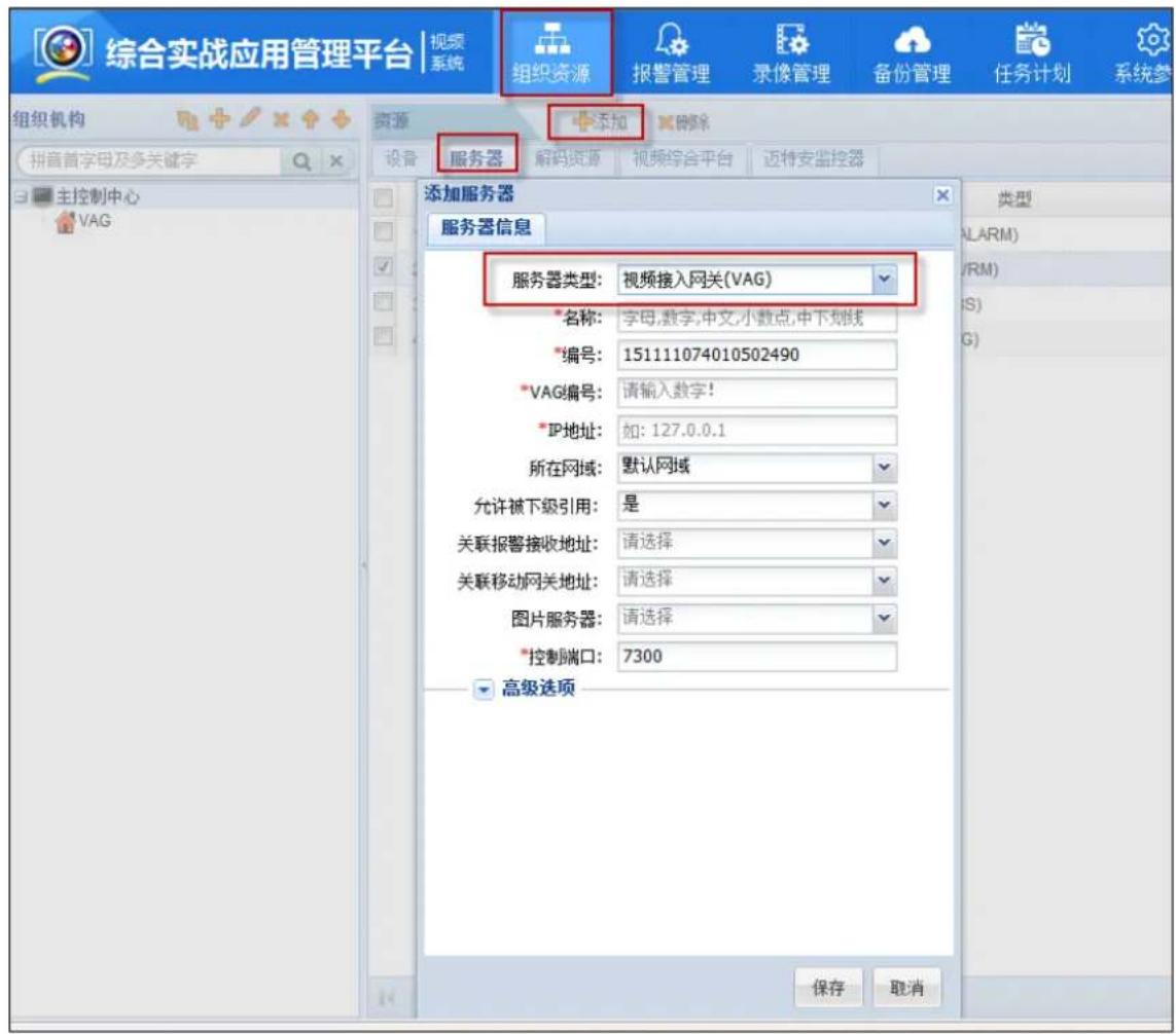
Number: generated by default or modified manually
VAG number: input the user's defined VAG number
IP address: IP address of installing VRM server is generally that of the installing platform software
3.1.2 Add Monitoring Device
1. Smart IPC Configuration
Configure the smart IPC according to the introduction of this chapter if you want to store the video stream and smart stream of Hikvision to the cloud storage system. If not the video storage of smart IPC, you can ignore this chapter and enter the chapter '4.4.2 Add Front-end Device' directly
Open Dual-VCA on the Smart IPC
On the configuration page of the smart IPC, enable dual-VCA on the Configuration->Video/Audio->Overlay for Stream Information page and click save.
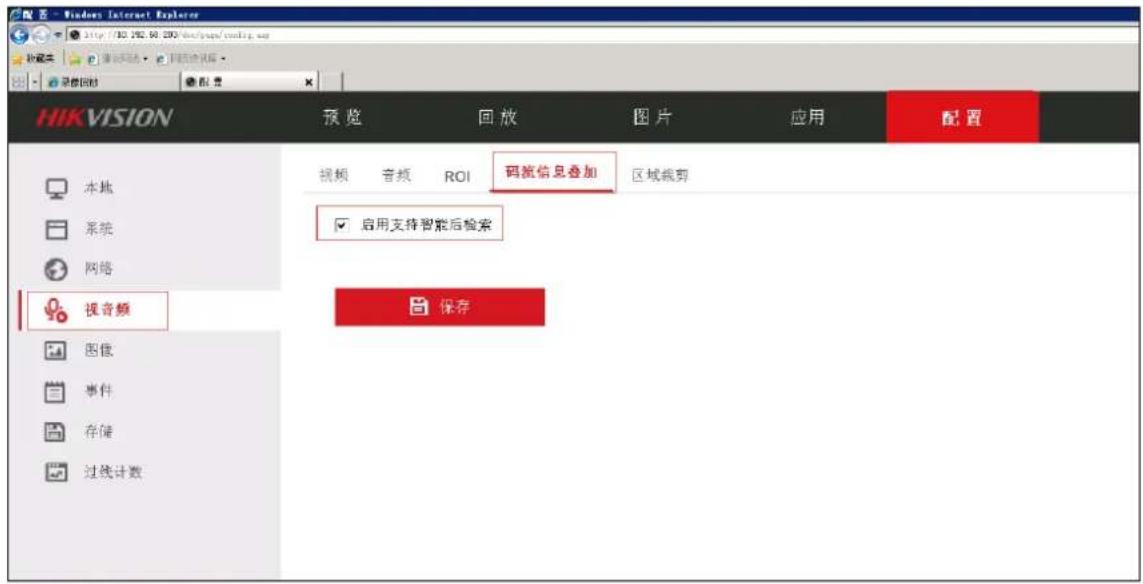
Draw Area on Smart Event
Click the 'Draw Area' on the Configuration->Smart Event->Regional Intrusion Detection (Border Detection) and draw the rule of the Smart Event, finally click save.
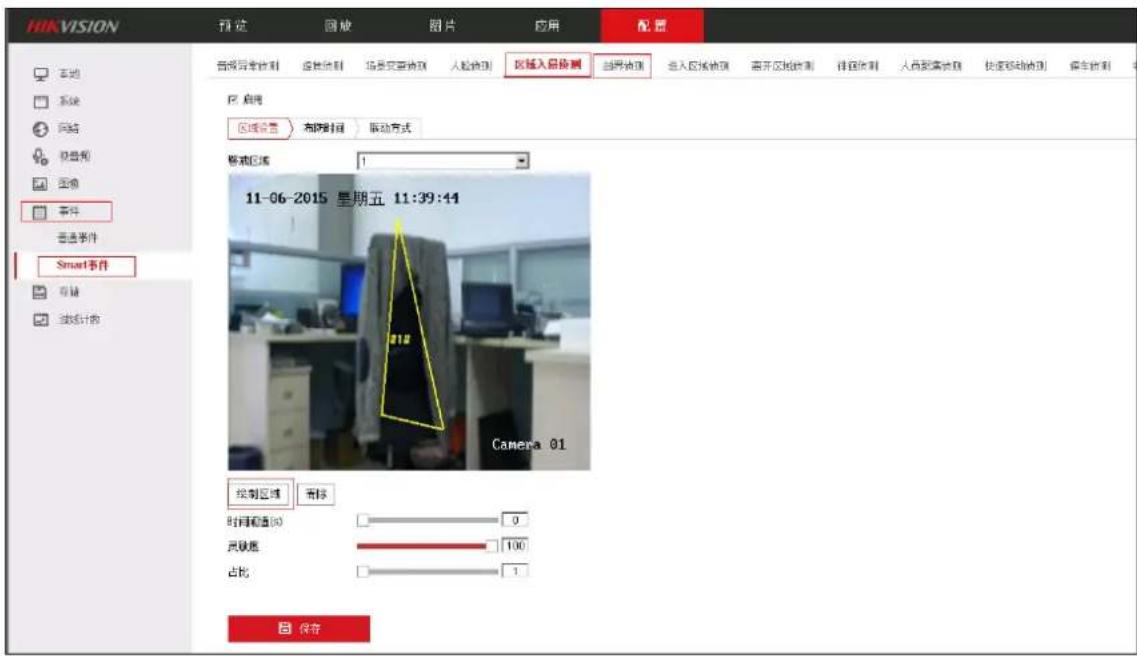
Fig. 4.2.2-2 Draw Area on Smart Event
Set Arming Schedule on Smart Event
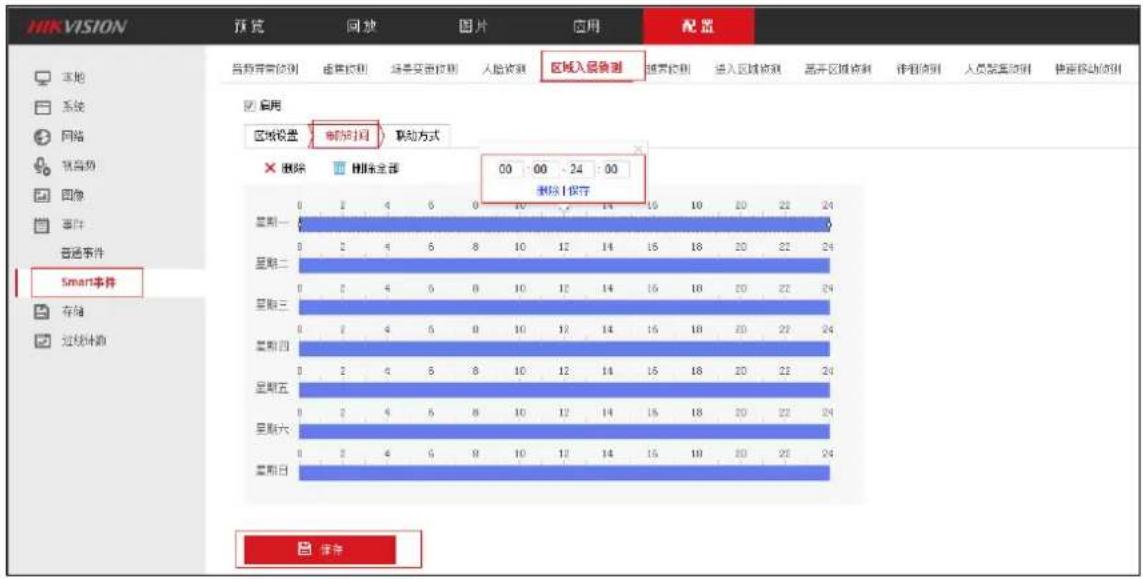
Enter the configuration page of the smart IPC, in the Configuration->Event->Smart Event->Regional Intrusion Detection->Arming Schedule page, the daily Arming Schedule is configured for 00:00-24:00, finally click save.
Front-end device is the front video device of the video server to take the initiative to connect to take the flow of the recording schedule. Add and manage it by using the iVMS-8200 monitoring application management system platform.
Login the management platform and click the 'Organizational Resource' function page in the management application module of the home page. Select the 'device' tab and add the device.
There are four modes to add the device, single IP, IP segment, single number and number segment. (the device of the GB and Ehome is added by the number). Taking the adding the single IP as an example, select the organization of the device as follows. Add the start IP address and end IP address if selecting to add the IP segment.
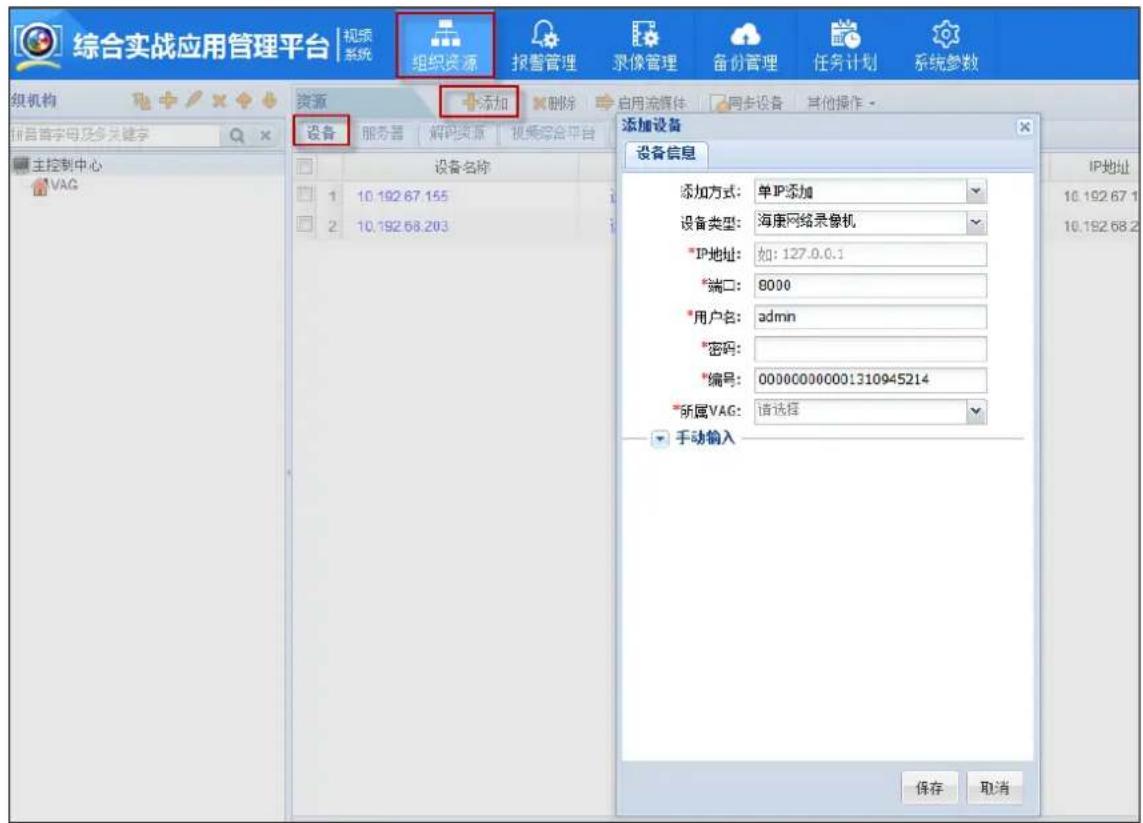
Operation procedures and instructions:
-
Select the organization of adding device, select the device and click 'add'
-
Click 'add mode' and select IP address in the connecting information.
- Select the type of the added device and add the IP address and password of the device. The port and number of the device are automatically generated.
- Select the associated VAG
- Click the save.
Note:
- The access of the device requires the support of the Video Access Gateway (VAG), and therefore confirming that the Video Access Gateway is connected to the platform before adding the device.
- Input the device name and the number of the channel when connecting the third party device.
- Select the device type 'Hikvision Smart IPC' if the front-end device is smart IPC. Login and configure the front-end device, see the specific configuration on the section 'Smart IPC Configuration'.
3. Add the Monitoring Point
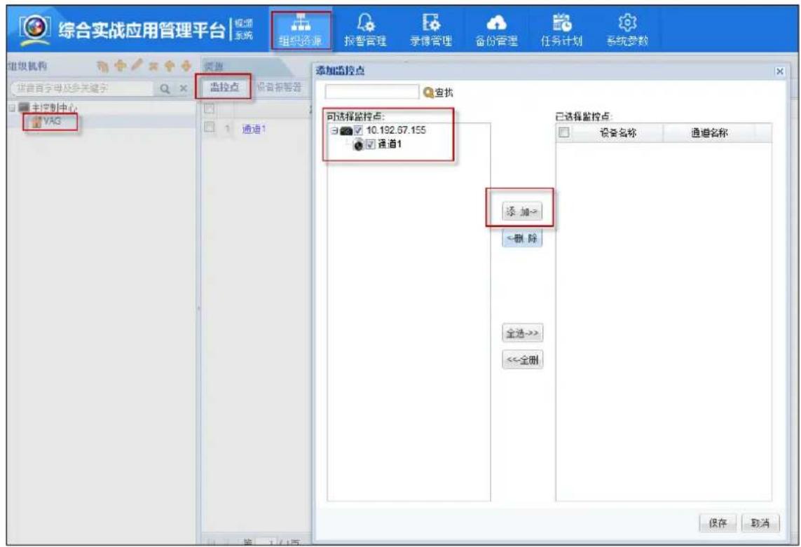
Login the iVMS-8200 management platform and click ‘Organizational Resource’ in the management application module of the home page. Enter function page of the ‘Organizational Resource’, select the monitoring areas which add the monitoring points, click add, enable the added monitoring points and save as follows.
3.1.3 Configure and Send down the Recording Schedule
1. Configure Recording Schedule
Login the iVMS-8200 management platform and click ‘Organizational Resource’ in the management application module of the home page. Click ‘Recording Management’ and enter function page of the ‘Recording Management’. Select the monitoring areas which add the monitoring points, configure and send down the Recording Schedule for the monitoring points in the Recording Management function page.
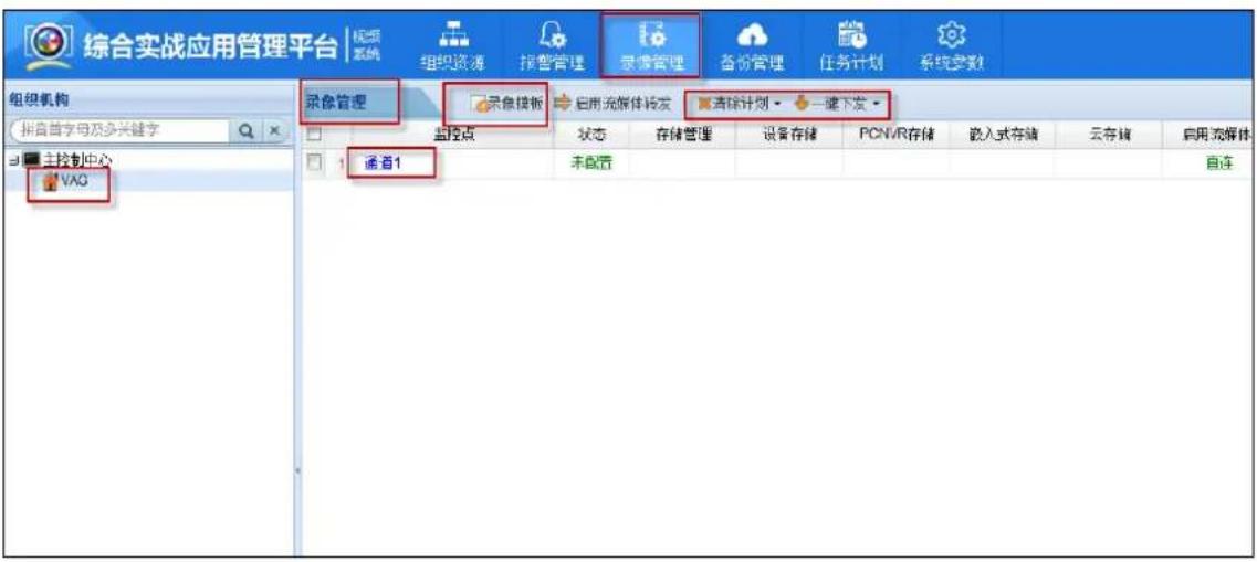
Click the corresponding link of the monitoring points (such as: 'channel one' monitoring point in the figure above) or click 'Recording Template' button after checking the corresponding monitoring point. Enter the page of configuring the Recording Template of the monitoring point as follows
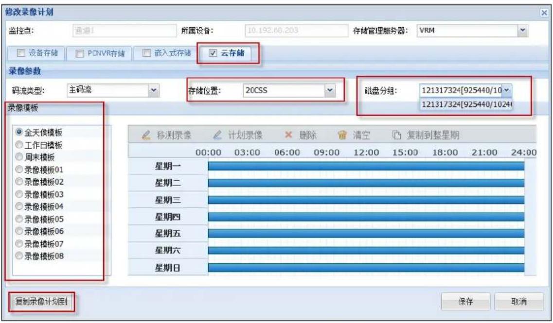
Configuration parameters are shown as follows:
Check the cloud storage check box
Recording Template: create the template of the Recording Schedule, including all-day template, weekday template and other eight templates which can be set up.
Storage location: select the CSS server which is added in the chapter 4.2.1
Disk grouping: select the resource pool ID in the cloud storage.
Click the 'copy to' button after the configuration, you can copy the configuration of the Recording Schedule to other Recording Schedule.
2. Send down the Recording Schedule
Select the configured Recording Schedule in the Recording Management list after configuring the Recording Schedule. Click the 'A Key for Sending down' button, then the Recording Schedule will be send down to the cloud storage. Cloud storage will store the recording according to the configuration of the monitoring points.
4 Picture Storage Configuration
At present, the main picture storage is divided into capture camera direct deposit and platform archived to save two ways, this chapter introduces two ways in this configuration.
4.1 Platform archived
4.1.1 Capture camera front-end configuration
Enter the 'configuration -> Device configuration -> Coding and storage' page, Click'Cloud storage'tags, As shown below:
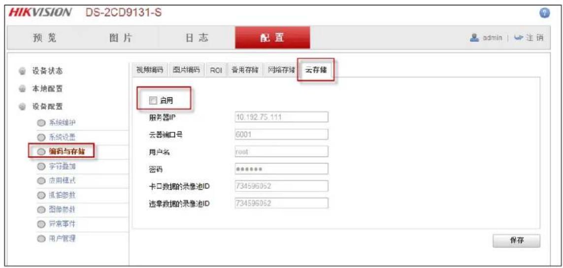
This chapter takes the traffic platform (iVMS-8600) as an example, introduces the configuration of cloud storage and industry platform to realize the picture storage. If other industries platform support platform archived of picture in capture camera to save, the specific configuration please refer to the platform user manual.
1. Add server
Login iVMS-8600 transportation platform, enter the 'resource management -> server' page, click the 'Add' button, add the following server:
1) VRM server
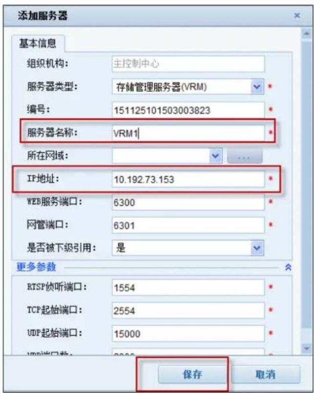
Note: 'IP Adress' please input the IP address of the platform.
2) VM server
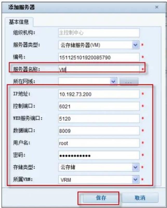
Note: 'IP Address' please input the cloud storage cluster virtual IP.
3) TDHS server
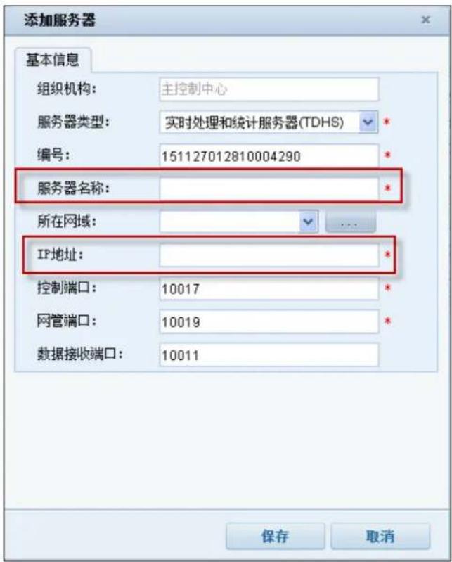
Note: 'IP Address' please input the IP address of the platform.
4) PMS server
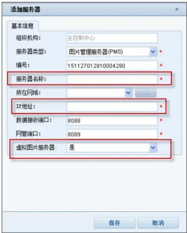
Note: 'IP Address' please input the IP address of the platform; 'virtual image server' option 'yes'.
5) TDAS server
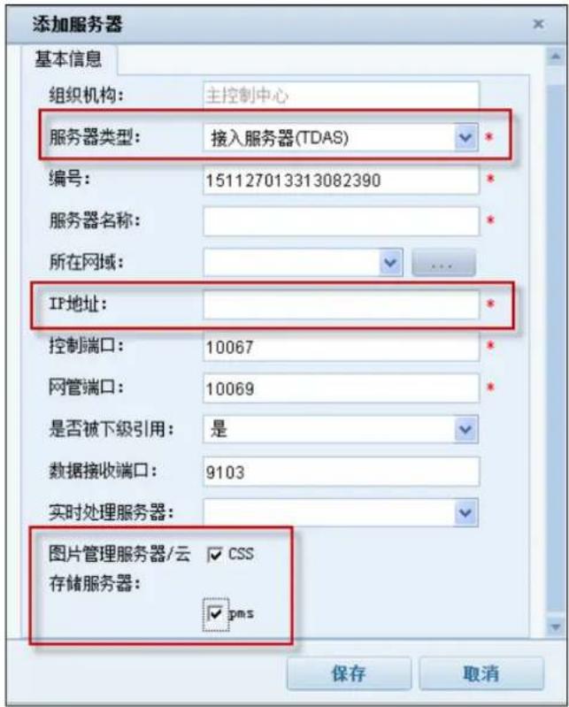
Note: 'IP Address' please input the IP address of the platform; and check the CSS and pms options box.
6) PAG server
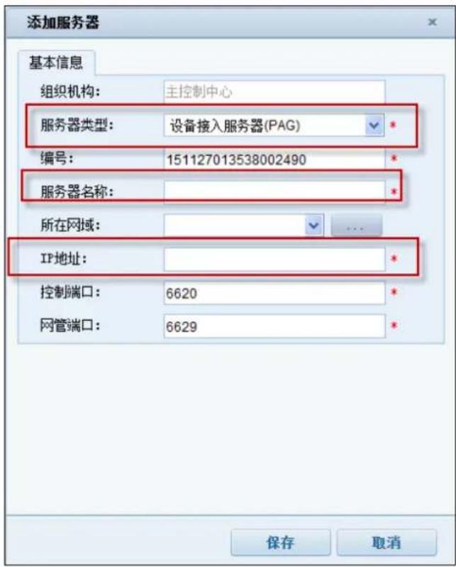
Note: 'IP Address' please input the IP address of the platform.
7) VRB server
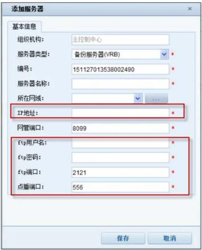
Note: 'IP Address' please input the IP address of the platform.
Among them, the VRB server configuration is completed, the need to click on the 【modified】button to configure the storage path, as shown in the following figure, select a storage path on the platform computer, enter the storage time, click 【save】
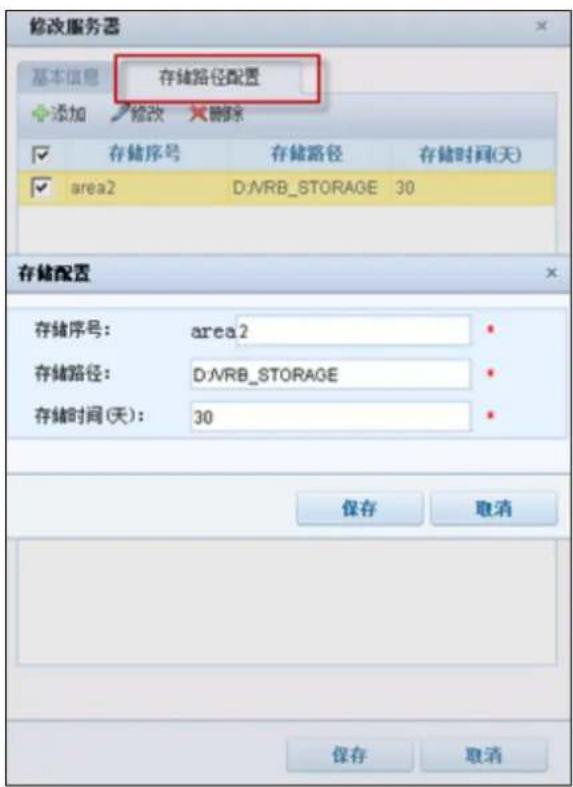
Note: "IP address" input platform IP address; receiving alarm mode selection "protection mode"; backup server selection"VRB"
2. Add storage pool
Login iVMS-8600 transportation platform, enter the "resource management - server page, as shown below:
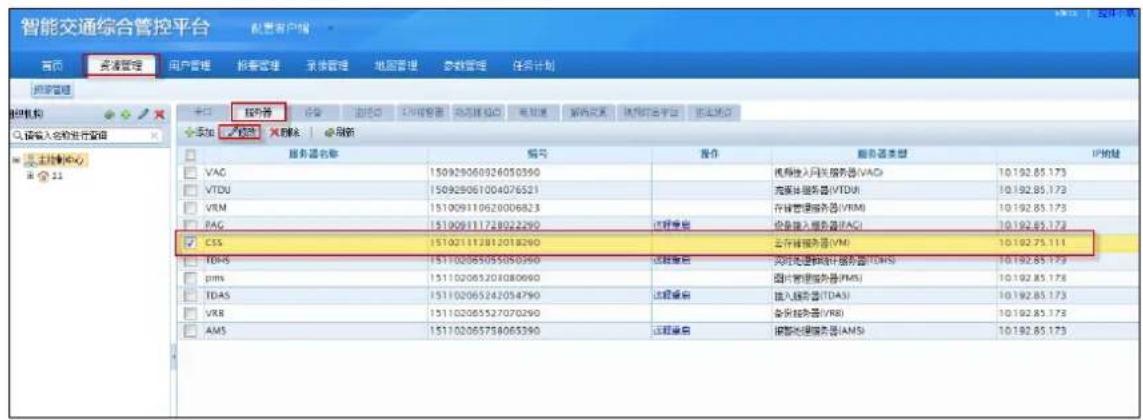
Check before you add the cloud storage server, click 'modify' button, in the server to modify the pop-up box, select the corresponding resource pool, click 'save', you can complete the storage pool to add. As shown in the following figure:
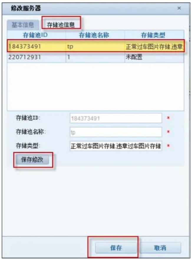
Figure 5.2.2-11 Add storage pool page
3. Capture machine picture storage configuration
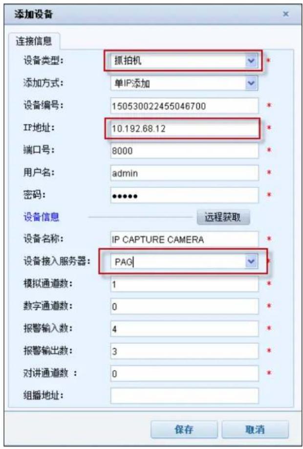
- Add front-end device
Login iVMS-8600 transportation platform, enter the 'resource management -> device' page, add device, as shown below:
- Add monitoring points
Login iVMS-8600 transportation platform, enter the ‘resource management- > monitoring point’ page, 【save】 the added capture camera front-end device channel add to the monitoring point.
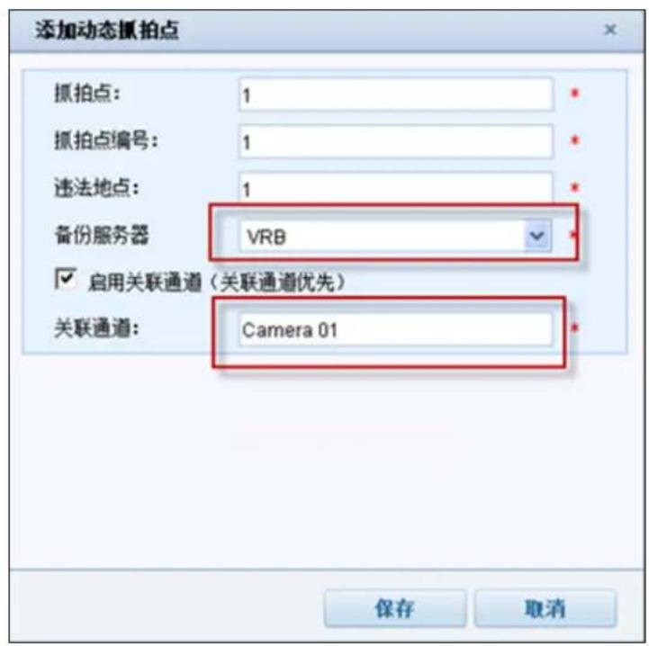
- Add dynamic capture point
Login iVMS-8600 transportation platform, enter the 'Resource Management > motion capture points"'page, add dynamic capture points, as shown below:
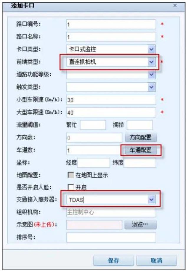
Login iVMS-8600 transportation platform, enter the 'resource management -> bayonet' page, add the bayonet, as shown below:
Above the lane configuration see figure below:
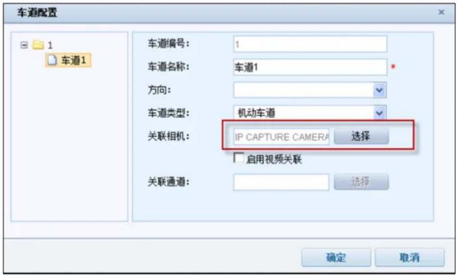
Note: Associated camera select the corresponding capture camera
Here the picture storage configuration has been configured, front-end devices capture images through the platform to save, can be stored in the cloud storage system.
5 Cloud Storage Functions Introduction
Intelligent cloud storage system provides video and picture storage, download and playback; file storage, download and other functions, and provides lots of interfaces. Users can view on cloud storage of internal information and help users more intuitive to understand the cloud storage internal operation status and operation information.
5.1 Recording Schedule Query
Login CVMN-WEB, enter the'access node --> the encoder 'page, which could query distributed monitoring point video schedule of cloud storage management system.
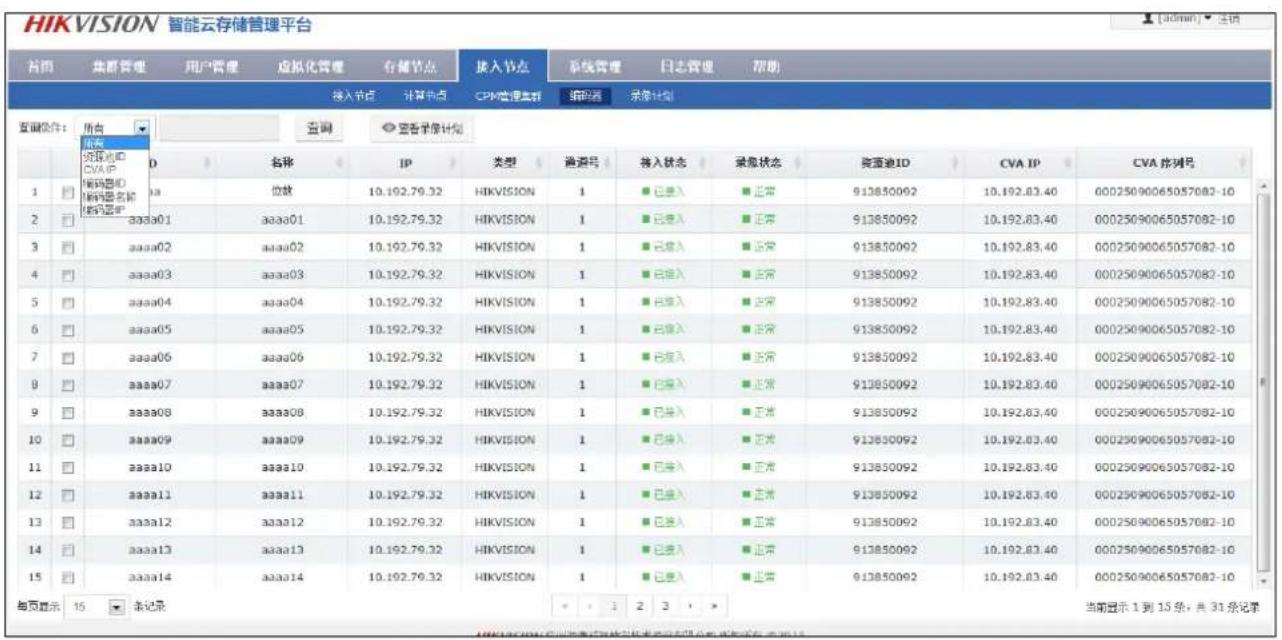
Figure 5.1-1 Recording schedule list query
Select the query conditions in the' query condition', can query according to the ID of resource pool, CVA IP, ID encoder, encoder name, encoder IP, or select 'all', click the 'search', according to the specified query conditions selected the Recording schedule of monitoring points, shown in the list below.
The ‘access state’ display the recording schedule of monitoring point issued, ‘accessed’ said the recording schedule has been issued to the normal access server, ‘No access’ said the monitoring point has been configured with a recording schedule, but not normal to access server. ‘The video status’s shows the current video program implementation, the’normal ‘state display recording schedule normal execution, ‘the abnormal recording ‘said recording schedule storage during the execution of the recording process has been abnormal,’”Flow abnormal‘said the video stream abnormal state plan implementation process from abnormal flow.
Check a single video program, click "view Recording schedule", you can view the monitoring points of the detailed Recording schedule template.
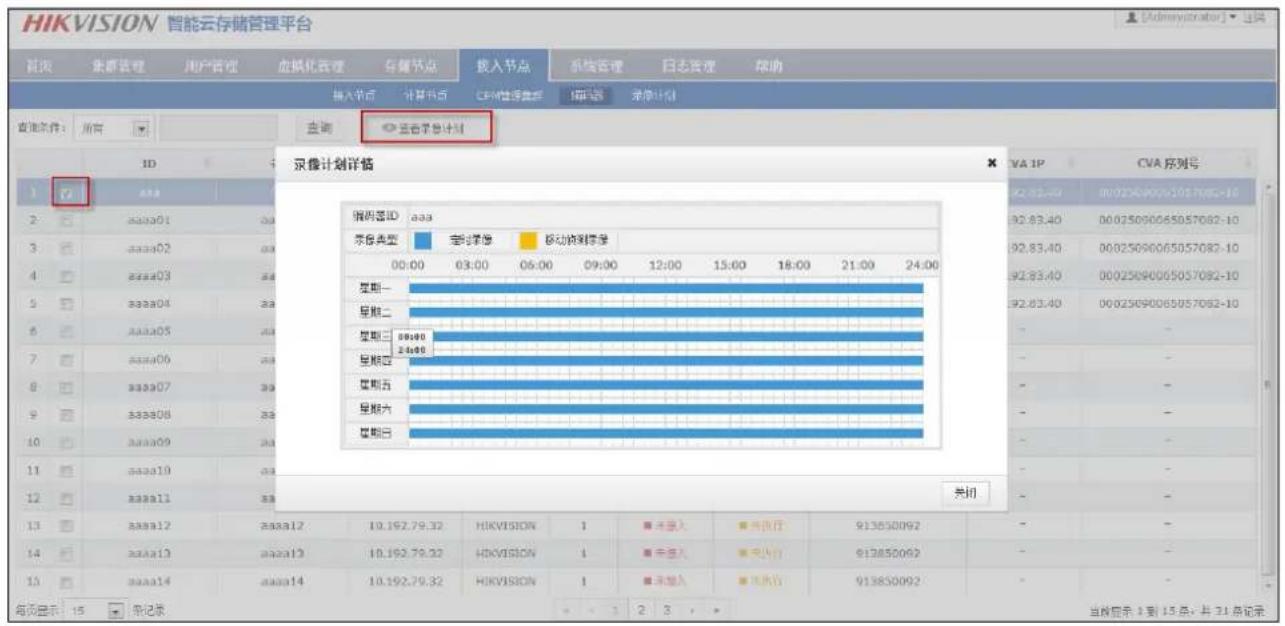
Figure 5.1-2 query recording schedule
5.2 Video Recording
5.2.1 Video query, playback, Downloading
Login iVMS-8200 platform, in the management of the home page, click on 'video playback', into the video playback page, as shown below:
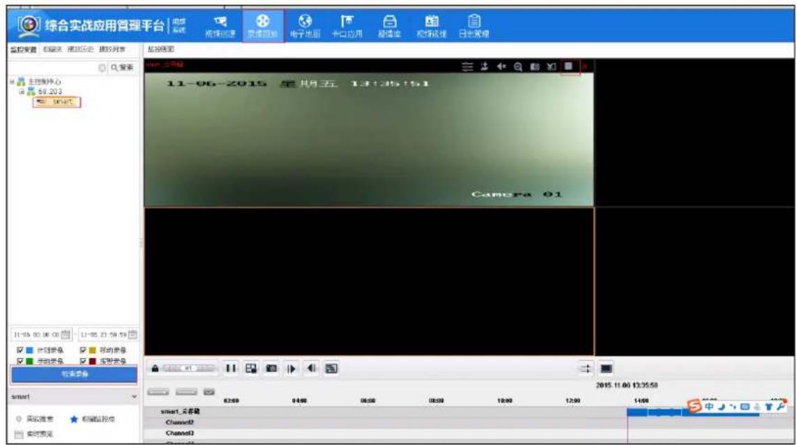
Select the corresponding monitoring points, then click button, The time axis on the bottom of the page shows the corresponding encoder video time.
Click playback button on the top right of the playback screen, you can play the normal playback.
While holding on the Ctrl key at the same time to drag the selection of a range of time, you can select a video, right click to download. You can also select the time range, through the right click to download. Or click the button to download the video.
5.2.2 Video locking
System supports external users to lock the specified video clips. For already locked video, the video segment data is not deleted when the loop is covered. First video query operation, select one or more segments of the video search, enter the lock time (unit: seconds), click "lock", you can set the video to lock state.
Lock time 0 indicates that the lock is not locked or unlocked, greater than 0 indicates the time of the lock.
Locked video data can be covered by loop after being unlocked. For the locking of the video data, the internal timing of the cloud storage will be checked, it will automatically unlock the lock time. At the same time, the system also supports the user to manually perform the video segment to unlock, the user manually unlock the operation mode with the video lock mode, lock up time for 0, said the immediate release.
Login iVMS-8200 platform, in the sector management application page, click on the 'video playback' enter the video playback page, select the corresponding monitoring points, then click the
检索录像
button, at the bottom of the page on the time axis shows the corresponding video encoder has period of time. Hold down the CTRL key, with the left mouse button to draw the lock time range, as shown below:
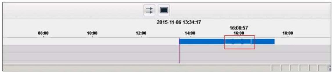
Figure5.2.2-1 Selected video
The time of selection, right click, select "lock lock file", after the success, as shown below
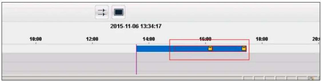
Figure 5.2.2-2 Video lock
Right click on the clip locked in the image above, click on the "unlock file", you can complete unlock.
5.2.3 Video backup
Users can enter the encoder ID, video time, data types, the purpose of the backup cloud IP and port, backup copies of the number of time to perform the backup task, the specified video data backup to the cloud or other cloud.
After the backup task is completed, the cloud storage to return to the ID of the backup task, the user can according to the backup task ID query backup schedule; or delete the backup task.
Video backup function has not yet docked with the platform, here is not about the docking procedures with the platform.
5.2.4 Recording annotation
Intelligent cloud storage system to the user specified video annotation, while providing query annotation, modify, delete, query according to the annotation of video and other features. Select the queried one or more segments of the video, click on the 'add tag' feature, enter the content to be added, to determine after the video segment to add video annotation. Can also add annotation contents of annotation have been added modifications. With the 'tag query' feature will be the time period of all the labels to check out, select a tag, the video segment can be deleted. Tag deletion does not affect the appropriate video segment. You can enter the label content to query video, cloud storage will return to the marked video segment.
Video annotation function has not yet docked with the platform, here is not about the docking procedures with the platform.
5.2.5 Search by Date/Month
Cloud storage system provides a search by date/month function, visual display of video daily / monthly.
1. Search by Date
According to the year and month of user input information, in the cloud storage system to check whether there is a video every day this month.
Enter the ‘calendar search’ page, select the ID encoder you needed, input the year and month, video type (input none query all types) and whether the lock and so on, click'search ‘, it shows that the month have a daily video.
Video annotation feature is still in connection with the industry platform, where not to tell the docking steps with the platform.
Cloud storage demo tools for calendar query results as shown below:
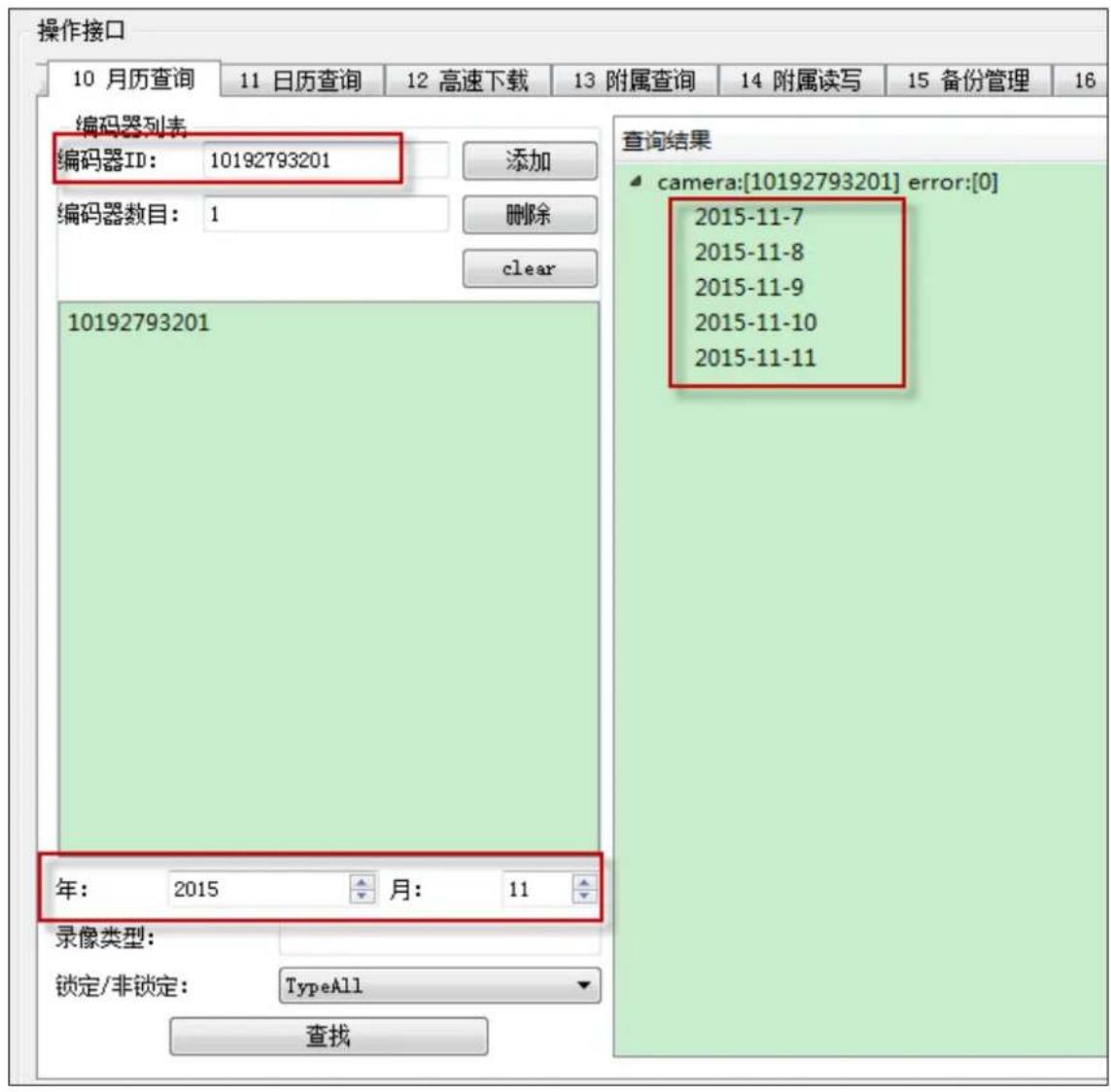
Figure 5.2.5-1 Search by Month
2. Search by Date
Users can specify one day in the calendar, the use of calendar query function to check the day 24 hours of video.
Login iVMS-8200 platform, in the management of the home page, click 'video operation and maintenance', into the video operation and maintenance page, click 'video operation and
maintenance' to enter the following web page:
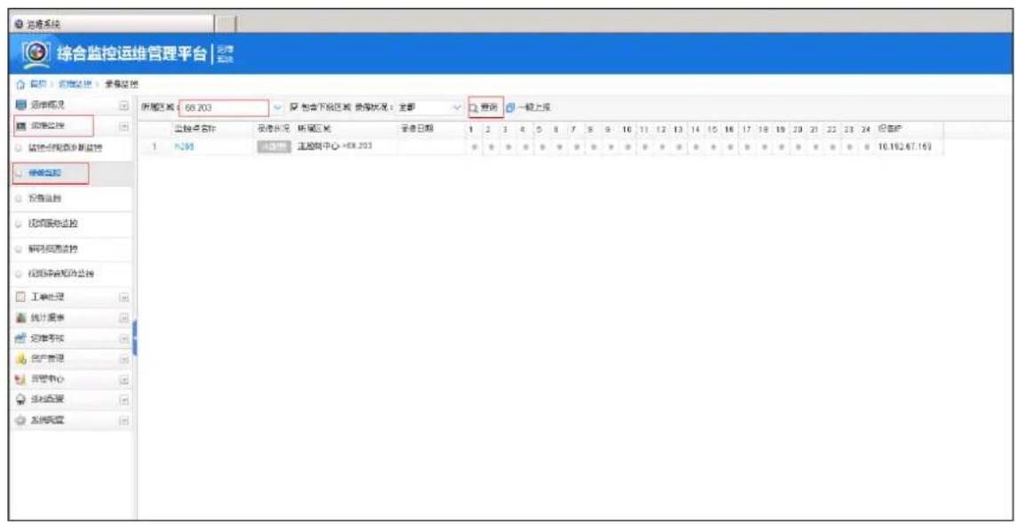
Figure 5.2.5-2 Search by Date
Select the area, click on the query, you can query the area under the various monitoring points of the video.
5.2.6 High speed downloading
The cloud storage system supports the concurrent downloading of video information from the same encoder to improve the download performance. High speed download support resume from break point
In the high-speed download before the end user can click to stop the download, HTTP functionality at the next to continue the unfinished download.
High speed download is still in connection with the industry platform, where not to tell the docking steps with the platform.
5.3 Smart Stream
5.3.1 Smart stream query
The user can according to the encoder ID, the time period, the lock attribute, inquires the
intelligent IPC to write the subsidiary section.
5.3.2 Smart stream downloading
Users can download time, according to the ID encoder attached information; also can input offset to resume from break point.
5.3.3 Smart retrieval
Cloud storage system provide smart retrieval function, according to the user's retrieval rules to retrieve video clips, search rules, including region entrance, line crossing detection. The retrieval rules given by the user, cloud storage by searching algorithm in accordance with the rules of video clips, returned to the user, for the user to thumbnail playback.
Login iVMS-8200 platform, in the management of the home page, click 'video playback', enter the video playback page, click on the intelligent playback button for video playback, appear as shown in the following window:
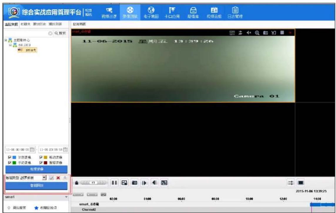
Figure 5.3.3-1 smart playback
In the image of the intelligent playback box, according to the need to select the appropriate type of intelligence, and then draw the intelligent retrieval area, you can carry out intelligent retrieval,
results of intelligent retrieval can be seen in the timeline below the page. As shown in the following figure:
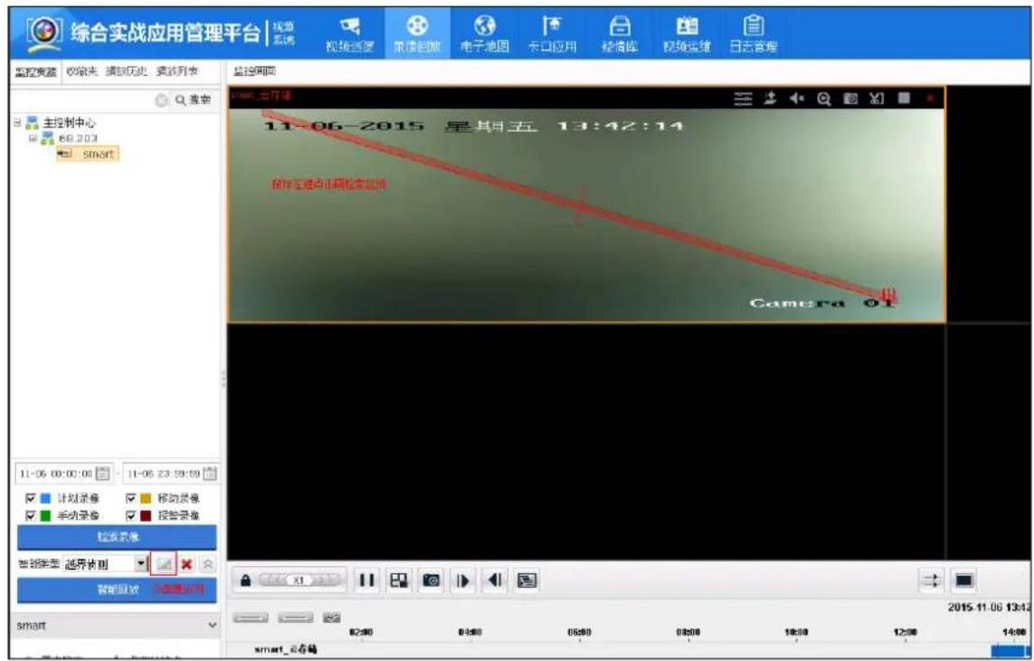
- Cloud storage system can store the forward over the picture from platform, and return to the platform a URL http address. Image URL generation rules: http:// cloud portal /pic port IP: encryption string
Eg:
Http://10.192.84.99:6120/pic?
0dd5096da-24ede11i433008--21007066eeeeai4b1*=ids1*=idp1*=tdpa*m4-30=6365=9i547?
The image generated URL address be input to the browser, you can directly view the picture through the browser
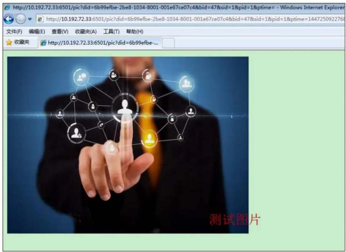
Figure 5.4.1-1 picture downloading via URL
5.4.2 Piceture downloading
- Support image downloading via URL using HTTP protocol
- Support image downloading by time segments (Encoder ID/Start time/End time/Type)
- Support options for Manual/Cancel/Stop downloading. Users can press the 'Stop Downloading' button to manually stop a task
- Support thumbnail downloading. Users can choose either a zoom scaling factor or a specific resolution for thumbnails.
5.4.3 Picture Locking
Users can lock and unlock a specific image. For the locked picture, it will not be overridden during cycle cover. System can specify a long lock, expire automatically unlock.Users can choose to lock picture via URL using HTTP protocol or can set lock on a series of picture sorted by date and
time.
5.4.4 Picture searching by picture
Picture searching by picture, according to the user's incoming channel, time range, similarity needs and target images, cloud storage will target picture and picture retrieval model after modeling to compare, return the picture URL conforms to the target model similarity set.
Enter the encoder ID, start the end of time, similarity, and import the target image, click the 'start' button, the results show that the similarity of the image URL collection.
The license plate attribute can be added as a matching condition to further improve the accuracy of alignment.
5.5 File
5.5.1 File upload
1. Ordinary way to upload
For files less than 1GB, the system is recommended to be uploaded in a common way; the user selects a file, enter the name of the Bucket and Object, and can upload the file to the cloud storage system. For data integrity and security, the cloud storage system will automatically back up the file two copies.
Ordinary way to upload files, if the upload fails, the user needs to re upload the entire file.

Figure 5.5.1-3 Upload files successfully
2. Slice way to upload
For files larger than 1GB, the system recommended by the slice upload; the user to select the
file, enter the Bucket name and the Object name, by docking platform to file into pieces the size of 2MB, and every piece of code, and each upload a slice. For data integrity and security, the cloud storage system will automatically back up the file two copies.
Slice way to upload files, if the upload fails, the user does not need to re upload the entire file; only upload failed to re upload can be.
5.5.2 File query
The system supports the user to obtain all Object list below Bucket. Because of the large number of Object under a single Bucket, the user can set the prefix, separator, the maximum number of returned to the number of these filtering conditions for query.
5.5.3 File download
System support the user to download the required Object, the user input Bucket name, Object name, as well as the size of the file you need to download, you can download files from the cloud storage.
Click on the 下载Object menu from demo Tools, enter the Bucket name, Object name, Download start end position (starting position to fill 0, end position to fill the file size), click the

button, you can download the file. As follows:
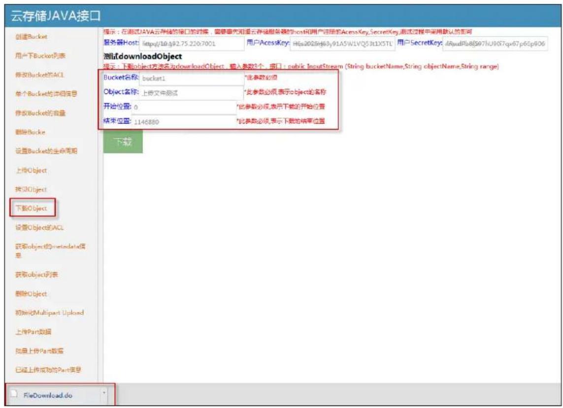
Figure 5.5.3-1 File download
5.5.4 File copy
Users can copy an already existed object, you can copy to the current Bucket or Bucket with read and write permissions of other users.
Click on the menu in the demo tool, enter the "source Bucket name", "the source
Object name", "destination Bucket name", "destination Object name", click the button, you can copy the file. As follows:
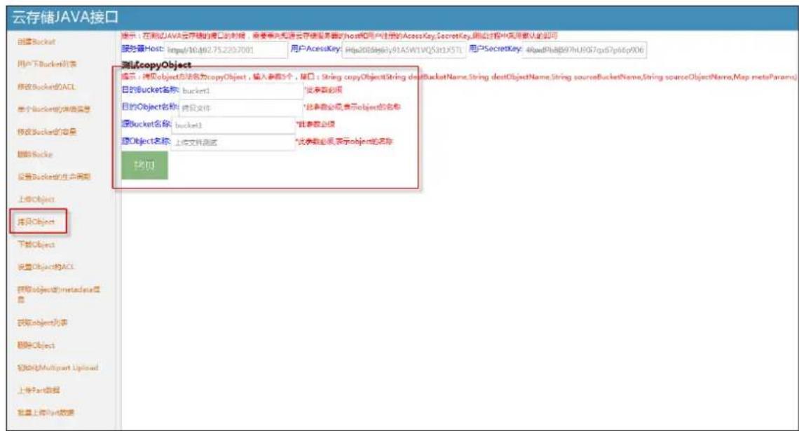
Copy the successful file can query, download; it can also copy again.
5.5.5 File permission setting
When users finish uploading data of Object, the permission of the file is set to private by default. If others should be granted permission to the file, the file permission can be set to public-read or public-read-write by the user.
5.5.6 File deletion
System supports the user to manually delete the Object; while the system will be based on the user set the Bucket storage cycle, automatically delete the expired Object
When users upload Object data over Object, the default permissions for private; if you need to open the Object permissions to other users, the system supports the user to reset the Object permissions for public-read or public-read-write.
5.6 System Log Download
While the system is running, server running log and operation log will be generated. These logs
can be used for analyzing the system status and for troubleshooting.
Log in CVMN-WEB((http://xx.xx.xx.xx:5120 (xx.xx.xx.xx is the IP for the virtual cluster))), go to Log Management -> Log Download, enter Module Category, Node IP and Search Category, press the
查询
button and the corresponding log file will be shown like below:
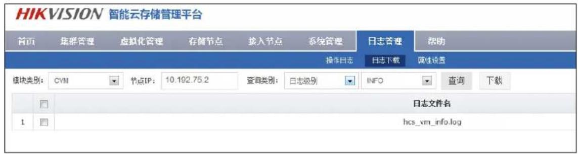
Figure 5.6-1 Log file query
Select the box in front of the log files, click on button, it can download the log file.
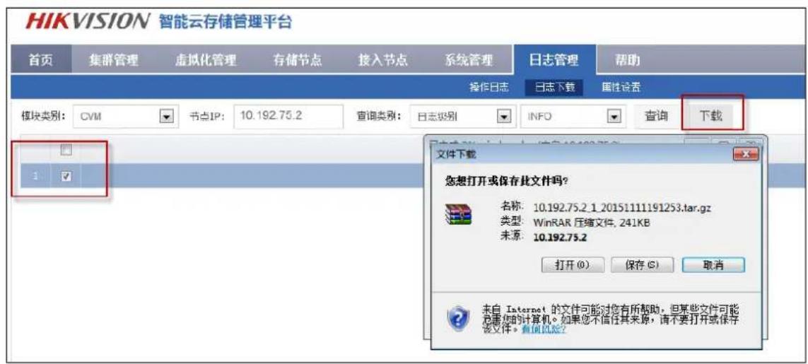
Figure 5.6-2 Log file download
- iVMS-5120-V2.0-HikCStor Operation Manual
- Attention of Smart Cloud Storage System
- Content
- Overview....1
- Standard Cloud System Deployment....11
- Video storage configuration....49
- Picture storage configuration 60
- Cloud storage functions introduction....76
- Introduction of Smart Cloud Storage Product
- Term Interpretation
- Product Function
- Smart Cloud Storage- Video Function
- Recording Management Function
- Smart Cloud Storage-Picture Function
- Smart Cloud Storage-Smart Stream Function
- Smart Cloud Storage-Operation and Maintenance Management Function
- Smart Cloud Storage System Deployment Structure Diagram
- Standard Cloud
- Standard Cloud System Deployment
- Preparation Before Installation
- Hardware Environment
- Software Environment
- Storage Point Deployment
- CVSN Internet Configuration
- CVSN Disk Initialization
- Ordinary Storage CVSN Node Deployment
- CVSN Software Installation
- CVSN System Format
- CVA Installation
- Management Node Deployment
- Installation of Management Node Deployment System
- Installation of Management Node Software
- Standard Double Clouds Machine HA Formation
- Bind Net Port
- HA Cluster Formation and Initialization
- Establish Standard Cloud Cluster
- Bind Network Interface
- Establish & Initialize Standard Cloud Cluster
- Configure Standard Cloud
- Configure CVS
- Create Domain
- Modify Domain
- Add CVS to Domain
- Create Resource Pool
- Modify Resource Pool
- Configure CVA
- Add CVA to Cluster
- Modify CVA Parameter
- Configure CCU
- Configure Synchronization Server
- Configure Group IP
- Resource Pool User Management
- Create User
- Modify User
- Bind User to Resource Pool
- Manage Bucket
- Create Bucket
- Query Bucket Information
- Modify Bucket
- Video Storage Configuration
- Video Storage Configuration of the Public Security Platform
- Add Server
- Add Video Record Management (VRM)
- Add Cloud Storage Server (CSS)
- Add Video Access Gateway(VAG)
- Add Monitoring Device
- Smart IPC Configuration
- Open Dual-VCA on the Smart IPC
- Draw Area on Smart Event
- Set Arming Schedule on Smart Event
- Note:
- Add the Monitoring Point
- Configure and Send down the Recording Schedule
- Configure Recording Schedule
- Send down the Recording Schedule
- Picture Storage Configuration
- Platform archived
- Capture camera front-end configuration
- Add server
- 1) VRM server
- 2) VM server
- 3) TDHS server
- 4) PMS server
- 5) TDAS server
- 7) VRB server
- Add storage pool
- Capture machine picture storage configuration
- - Add front-end device
- - Add monitoring points
- - Add dynamic capture point
- Cloud Storage Functions Introduction
- Recording Schedule Query
- Video Recording
- Video query, playback, Downloading
- Video locking
- 检索录像
- Video backup
- Recording annotation
- Search by Date/Month
- Search by Date
- Search by Date
- High speed downloading
- Smart Stream
- Smart stream query
- Smart stream downloading
- Smart retrieval
- Piceture downloading
- Picture Locking
- Picture searching by picture
- File
- File upload
- Ordinary way to upload
- Slice way to upload
- File query
- File download
- File copy
- File permission setting
- File deletion
- System Log Download
- 查询
Brand : Hikvision
Model : DS-A71024R-CVS
Category : Server