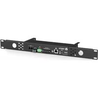
Watchdog 100 - Moniteur environnemental Emerson - Free user manual and instructions
Find the device manual for free Watchdog 100 Emerson in PDF.


| Product Type | Self-contained environmental monitor with onboard temperature/humidity sensor |
| Power Supply | 6-12 VDC, 2 A (recommended); optional Power-over-Ethernet (PoE) |
| Ethernet Interface | 10/100 Mb, full duplex |
| Supported Protocols | HTTP, HTTPS (TLS v1.2), SMTP/POP3, ICMP, DHCP, TCP/IP, NTP, Syslog, SNMP (v1/2c/3), GDP |
| User Interfaces | Web GUI, SNMP, JSON API |
| Onboard Sensors | Temperature (accuracy ±0.5°C from -20°C to 80°C), Humidity (accuracy ±2% from 20% to 80%), Dew Point (calculated) |
| External Sensor Ports | 2 RJ12 ports (digital, plug-n-play) and 4 analog I/O ports (0-5 Vdc or dry contact) |
| External Sensor Types | SRT, GTHD, GT3HD, RTAFHD3, A2D (plug-n-play); FS, PFS, RPDS, SA9, IVS, WSCK (analog) |
| Relay Output | 1 output relay; ratings: DC 60V/30W, AC 30Vrms/1A; configurable for alarm or manual control |
| Alarm/Notification Features | Alarm and warning events with threshold, delay, latching; notifications via email (up to 5 addresses) or SNMP traps (up to 2 IPs) |
| Data Logging | Logs data every 60 seconds; downloadable in CSV or JSON format; data graphing available |
| Operating Temperature | -4°F to 113°F (-25°C to 45°C) |
| Storage Temperature | -40°F to 176°F (-40°C to 80°C) |
| Operating Humidity | 5% to 95% (non-condensing) |
| Operating Elevation | 0 ft to 6,561 ft (0 m to 2,000 m) |
| Mounting | Mount with appropriate hardware; ensure even mechanical loading |
| Maintenance | No user serviceable parts; power off before installing or removing equipment |
| Safety Certifications | UL listed, FCC Class A, RoHS/WEEE compliant |
| Default IP Address | 192.168.123.123 (subnet mask 255.255.255.0, gateway 192.168.123.1) |
| Firmware Update | Via web interface; upload .ZIP archive containing firmware package |
Frequently Asked Questions - Watchdog 100 Emerson
User questions about Watchdog 100 Emerson
0 question about this device. Answer the ones you know or ask your own.
Ask a new question about this device
Download the instructions for your Moniteur environnemental in PDF format for free! Find your manual Watchdog 100 - Emerson and take your electronic device back in hand. On this page are published all the documents necessary for the use of your device. Watchdog 100 by Emerson.
USER MANUAL Watchdog 100 Emerson
Installer/User Guide
The information contained in this document is subject to change without notice and may not be suitable for all applications. While every precaution has been taken to ensure the accuracy and completeness of this document, Vertiv assumes no responsibility and disclaims all liability for damages resulting from use of this information or for any errors or omissions. Refer to other local practices or building codes as applicable for the correct methods, tools, and materials to be used in performing procedures not specifically described in this document.
The products covered by this instruction manual are manufactured and/or sold by Vertiv. This document is the property of Vertiv and contains confidential and proprietary information owned by Vertiv. Any copying, use or disclosure of it without the written permission of Vertiv is strictly prohibited.
Names of companies and products are trademarks or registered trademarks of the respective companies. Any questions regarding usage of trademark names should be directed to the original manufacturer.
Technical Support Site
If you encounter any installation or operational issues with your product, check the pertinent section of this manual to see if the issue can be resolved by following outlined procedures. Visit https://www.VertivCo.com/en-us/support/ for additional assistance.
TABLE OF CONTENTS
1 Overview 1
1.1 Environmental 1
1.2 Electrical 2
1.3 Networking 2....
1.3.1 Ethernet 2
1.3.2 Protocols 2
1.3.3 User Interfaces 2
1.4 Onboard Sensors 2....
1.5 External Sensors 2.
2 Installation 5
2.1 Network Setup 5
2.2 Regulatory Compliance 8
2.2.1 Underwriters Laboratories (UL) 8
2.2.2 Federal Communications Commission (FCC) 9
2.2.3 RoHS/WEEE 9
3 Web Interface.... 11
3.1 Home Page 11
3.1.1 Sensors tab 12
3.1.2 System tab 19
4 Appendices.... 33
Appendix A: Technical Support 33
Appendix B: Using Microsoft Exchange as an SMTP Server 33
Appendix C: Product Specific Safety Notices 35
1 OVERVIEW
The Geist™ Watchdog 100 is a self-contained environmental monitor with an onboard temperature/humidity sensor. Equipped with two digital RJ12 sensor ports, the Watchdog 100 also has four I/O ports for connecting analog external sensors. The Watchdog 100 can be optionally configured at the factory to support Power-Over-Ethernet (PoE).
All onboard and external sensors are read every five seconds. Sensor data collected by the Watchdog 100 provides useful trend analysis data.
Figure 1.1 Watchdog 100

natural_image
Front view of a black VERTIV network interface unit with ports and connectors (no readable text or symbols beyond branding)1.1 Environmental
The operational environmental limits pertaining to temperature, humidity and elevation are as defined in the following tables.
Table 1.1 Temperature Limits
| STATE MINIMUM MAXIMUM | ||
| Operating -4°F (-25°C) 113°F (45°C) | ||
| Storage -40°F (-40°C) 176°F (80°C) | ||
Table 1.2 Humidity Limits
| STATE MINIMUM MAXIMUM | ||
| Operating 5% | 95% (non-condensing) | |
| Storage 5% | 95% (non-condensing) | |
Table 1.3 Elevation Limits
| STATE MINIMUM MAXIMUM | ||
| Operating 0 ft (0 m) | 6561 ft (2000 m) | |
| Storage 0 ft (0 m) | 50,000 ft (15,240 m) | |
1.2 Electrical
The recommended Power Supply is 6-12 Volts DC, 2 Amps. Some models are equipped with Power-Over-Ethernet (PoE). Also, see the product nameplate for additional rating limits.
1.3 Networking
The product communications requirements are defined in the following sections.
1.3.1 Ethernet
The Ethernet link speed for this product is: 10/100 Mb; full duplex.
1.3.2 Protocols
The communications protocols supported by this product include: HTTP, HTTPS (TLS v1.2), SMTP/POP3, ICMP, DHCP, TCP/IP, NTP, Syslog, SNMP (v1/2c/3) and GDP.
1.3.3 User Interfaces
This product supports SNMP, Web GUI and JSON API user interfaces.
1.4 Onboard Sensors
Watchdog 100 contains the following onboard sensors:
- Temperature: Measures temperature and can be displayed in °F or °C. The accuracy is ±0.5 °C from -20 °C to 80°C.
NOTE: This sensor may be heated by internal circuitry in the unit; a temperature offset is available to re-calibrate.
- Humidity: Measures the percent of water vapor in the air within + / - 2% accuracy within a range from 20% to 80% .
- Dew Point: Calculated measurement of temperature at which moisture in the air turns to liquid, based on the humidity and temperature measurements.
1.5 External Sensors
The Watchdog 100 units come equipped with four analog I/O ports for connecting additional external sensors such as Flood and Door Sensors. The four ports are designed to accept a 0-5 Vdc analog input; alternatively, an internal 100K pull up resistor to 5 V allows for the use of dry contacts. The Analog I/O port input is converted to a digital number ranging from 0 to 99 and is displayed on the Sensors page. Unused I/O ports will display a value of 99. This range can be adjusted on the display page allowing the user to modify the value to make it more meaningful to the user.
Flood sensors act as conductivity bridges. Moisture across the contacts causes the value to drop. Door switches can be wired in a serial connection; if the chain is broken the entire group is classified as open. The limiting factor on the I/O ports is the length of the wire, found to be around 400 feet.
Figure 1.2 Watchdog 100

natural_image
Black VERTIV Sensor module with coiled cable, no visible text or symbols on the device itselfThe available sensors are:
Plug-n-play sensors:
• SRT: Stainless External Temperature
• GTHD: Temperature/Humidity/Dew Point
• GT3HD: Temperature/Humidity/Dew Point (standard comes with two additional temperature sensors [SRTs])
• RTAFHD3: Temperature/Air Flow/Humidity/Dew Point
• A2D: Connects analog I/O sensors to RJ12 sensor ports
Analog I/O sensors:
• FS: Flood (Water) Sensor
• PFS: Power Failure Sensor
• RPDS: Door Switch Kit
• SA9: Smoke Alarm
• IVS: Isolated DC Voltage Sensor
• WSCK: Leak Detection Kit
Plug-n-play external sensors can be attached to the unit at any time via the RJ12 connectors on the face of the unit. In some cases splitters may be required to add additional sensors. Each sensor has a unique serial number and is automatically discovered and added to the web page. Up to four sensors may be connected to the Watchdog 15.
The display order of the sensors on the web page is determined by the serial number of each sensor. Friendly names for each sensor can be customized on the Sensors Overview page.
NOTE: Sensors use CAT5, CMP wire and RJ12 connectors. Wiring must be straight-through: reverse polarity will temporarily disable all sensors until corrected. Sensors use a serial communication protocol and are subject to network signaling constraints dependent on shielding, environmental noise, and length of wire. Typical installations allow runs of up to 600 feet of sensor wire.
This page intentionally left blank
2 INSTALLATION
Prior to installation, verify the following pre-installation guidelines:
- If the Watchdog 100 is installed in a cabinet, the ambient temperature of the rack should be no greater than 113^ (45°C).
• Install the Watchdog 100 with required airflow for safe operation of equipment. - Mount the Watchdog 100 with even mechanical loading to prevent a hazardous condition.
To install the Watchdog 100:
- Using appropriate hardware, mount the unit in the desired location.
- Connect the AC power supply to an appropriate source, or if using PoE, connect the Ethernet cable to a PoE-enabled switch port.
- Connect any external plug-n-play sensors into the devices' RJ12 ports.
2.1 Network Setup
The Watchdog 100 has a default IP address for initial setup and access. Once an IP address is assigned, or DHCP is enabled, the default IP address is no longer active.
To restore the default IP address and reset all user-account information:
If the user-assigned address or passwords are lost or forgotten, press and hold the network-reset button located under the Ethernet port for 100 seconds.
To erase all user settings and restore the unit back to its factory default state:
- Disconnect power from the Watchdog 100.
- Press and hold the network reset button while powering up the unit.
The Network page, located under the System tab, allows you to assign the network properties manually, or use DHCP to connect to your network. Access to the unit requires the IP address to be known. Use of a static IP or a reserved DHCP is recommended. The default address is shown on the front of the unit as follows:
• IP Address: 192.168.123.123
- Subnet Mask: 255.255.255.0
• Gateway: 192.168.123.1
To access the unit the first time, you must temporarily change your computer's network settings to match the 192.168.123. xxx subnet. To set up the unit, connect it to your computer's Ethernet port, then follow the appropriate instructions for your computer's operating system.
To set up the network for a Windows operating system:
- Access the network for your operating system.
• Using Windows 2000, XP or Server 2003, click Start - Settings - Network Connections.
- Using Windows 7 or Server 2008, click Start - Control Panel - Adjust your Computer's Settings - View Network Status and Tasks - Change Adapter Settings or click Start - Settings - Control Panel - Network and Sharing Center - Change Adapter Settings.
- Using Windows 8 or Server 2012, move the mouse to the bottom or top right corner, click Settings - Control Panel - Large or Small Icons - Network and Sharing Center - Change Adapter Setting
• Using Windows 10, click Start - Network and Internet - Change Adapter Settings.
- Locate the entry under LAN, High-Speed Internet or Local Area Connection which corresponds to the network card (NIC). Double-click on the network adaptor's entry in the Network Connections list.
NOTE: Most computers have a single Ethernet NIC installed, but a WiFi or 3G adaptor also shows as a NIC in this list. Be sure to choose the correct entry.
- Click Properties to open the Local Properties window.
Figure 2.1 Local Area Connection Properties

- Select Internet Protocol Version 4 (TCP/IPv4) from the list and click Properties.
NOTE: If you see more than one TCP/IP entry, as in the example above, the computer may be configured for IPv6 support as well as IPv4; make sure to select the entry for the IPv4 protocol. Write down the current NIC card settings so you can restore them to normal after you complete the setup procedure.
Figure 2.2 Internet Protocol Version 4

- Choose Use the following IP address, set the IP address to 192.168.123.1 and the Subnet Mask to 255.255.255.0.
NOTE: For initial setup, Default Gateway and the DNS Server entries can be left blank. Select OK - OK to close both the Internet Protocol Properties and Local Properties windows.
- In a web browser, enter http://192.168.123.123 to access the unit.
NOTE: If you are setting up the unit for the first time, or if the unit has been reset back to factory defaults via the network-reset button, the unit requires you to create an Admin account and password before you can proceed.
- After the admin account is created, log into the unit.
- From the default sensors page, navigate to the System tab, then the Network page to configure the device's network properties. The unit's IP Address, Subnet Mask, Gateway and DNS settings can be assigned manually or acquired via DHCP.
- Click Save.
NOTE: After the changes are saved, the browser is no longer able to reload the web page from the 192.168.123.123 address and it displays the "Page not Found" or "Host Unavailable" message; this is normal. After you are finished configuring the unit's IP address, repeat the previous steps changing the computer's Ethernet NIC card settings to the ones you wrote down prior to changing them.
To set up the network for a MAC:
- Click the System Preferences icon on the Dock, and choose Network.
Figure 2.3 Mac System Preferences

- Ensure Ethernet is highlighted on the left side of the NIC window. In most cases, there will be one Ethernet entry on a Mac. Write down the current settings so you can restore them to normal after you have completed the setup procedure.
- Select Manually from the Configure IPv4 drop-down list, then set the IP Address to 192.168.123.1, the Subnet Mask to 255.255.255.0 and click Apply.
NOTE: The Router and DNS Server settings can be left blank for this initial setup. In a web browser, enter http://192.168.123.123 to access the unit. If you are setting up the unit for the first time, or if the unit has been reset back to factory defaults via the network-reset button, the unit requires you to create an Admin account and password before you can proceed.
- After the admin account is created, log into the unit.
- From the default sensors page, navigate to the System tab and the Network page to configure the device's network properties. The unit's IP Address, Subnet Mask, Gateway and DNS settings can either be assigned manually, or acquired via DHCP.
- Click Save.
NOTE: After the changes are saved, the browser is no longer able to reload the web page from the 192.168.123.123 address and displays the "Page not Found" or "Host Unavailable" message; this is normal. After you are finished configuring the unit's IP address, repeat the previous steps changing the computer's Ethernet NIC card settings to the ones you wrote down prior to changing them.
2.2 Regulatory Compliance
Vertiv products are regulated for Safety, Emissions, and Environment Impact per the following agencies and policies.
2.2.1 Underwriters Laboratories (UL)
UL Standards are used to assess products; test components, materials, systems and performance; and evaluate environmentally sustainable products, renewable energies, food and water products, recycling systems and other innovative technologies.
The UL standards specific to this equipment are as noted on the device nameplate.
2.2.2 Federal Communications Commission (FCC)
The Federal Communications Commission (FCC) regulates interstate and international communications by radio, television, wire, satellite, and cable in all 50 states, the District of Columbia and U.S. territories. An independent U.S. government agency overseen by Congress, the commission is the United States' primary authority for communications laws, regulation and technological innovation.
The FCC standards specific to this equipment are:
This Class A device complies with part 15 of the FCC Rules. Operation is subject to the following two conditions: (1) This device may not cause harmful interference, and (2) this device must accept any interference received, including interference that may cause undesired operation.
This Class A digital apparatus complies with Canadian ICES-003.
WARNING! Changes or modifications to this unit not expressly approved by the party responsible for compliance could void the user's authority to operate this equipment.
2.2.3 RoHS/WEEE
RoHS, also known as Lead-Free, stands for Restriction of Hazardous Substances. RoHS, also known as Directive 2002/95/EC, originated in the European Union and restricts the use of six hazardous materials found in electrical and electronic products. All applicable products in the EU market after July 1, 2006 must pass RoHS compliance. RoHS impacts the entire electronics industry and many electrical products as well.
WEEE stands for Waste from Electrical and Electronic Equipment. WEEE Directive 2002/96/EC mandates the treatment, recovery and recycling of electric and electronic equipment (90% ends up in landfills). All applicable products in the EU market must pass WEEE compliance and carry the Wheelie Bin sticker.
See product label for RoHS/WEEE compliance marks.
This page intentionally left blank
3 WEB INTERFACE
The unit is accessible via a standard, unencrypted HTTP connection as well as an encrypted HTTPS (SSL) connection. The following web pages are available.
3.1 Home Page
The Home page gives both current and historical views of the unit's data. Readings for the onboard temperature, humidity and dew point sensors, along with all external sensors such as the A2D converter, are shown. Plug-n-play external sensors appear under the onboard sensors when attached.
Figure 3.1 Home Page
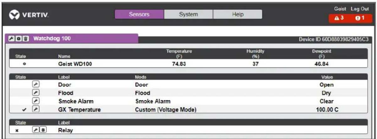
Table 3.1 Home Page Descriptions
| NUMBER NAME DESCRIPTION | ||
| 1 | Sensors, System and Help Tab | Mouse over to show sub-menus:Sensors: Overview, Alarms and Warnings, Logging and Data GraphingSystem: Users, Network, Web Server, Time, Email, SNMP, Syslog, Admin, Locale and Utilities. Refer to the appropriate section under System.Help: Info, Support Site. Refer to the appropriate section under Help. |
| 2 Log In/Log Out | Click to log in or log out of the unit.NOTE: Both username and password are case sensitive and no spaces are allowed. Prohibited characters for username are: $& `:<>[ ] { }"+%@/ ; =?\^|-', | |
| 3 Alarms and Warnings Indicates the number of alarms and warnings currently occurring, if any. | ||
| 4 Device ID Unique product identification and cannot be changed. May be required for technical support. | ||
5 Configurati  n - Modifies label name and adjusts temperature offset of onboard temperature sensor . n - Modifies label name and adjusts temperature offset of onboard temperature sensor . | ||
6 Operation  | Restores device defaults. | Restores device defaults. | ||
| 7 | Device Label | Displays the user-assigned label of this unit (See 'Configuration and Operation', 'Device Labeling'.) |
| 8 Vertiv Logo Clicking on this logo from any page will reload the home page. | ||
| 9 Connected Sensors Displays State, Temperature, Humidity and Dew Point of connected sensors. | ||
NOTE: You must log in before making any changes. Only users with Control-level authorizations have access to these settings.
3.1.1 Sensors tab
The Sensors tab page is used to modify a device's label and temperature offset, delete a sensor and perform the procedures for alarms and warnings, logging and the data graph.
NOTE: You must log in before making any changes. Only users with Control-level authorizations have access to these settings.
Modifying the device label and temperature offset
To modify the device's label and temperature offset:
- On the home page, click the Sensors tab.
- Click the Configuration icon.
NOTE: The name is the device's factory name or model, and cannot be changed.
- Click Save.
Deleting a sensor
To delete a device with it's associated data and configuration:
-
On the home page, click the Sensors tab.
-
Click the Delete icon and following the confirmation prompt.
NOTE: The deleted device must be removed; otherwise, it will be re-detected and shown on the page.
Figure 3.2 Deleting a Sensor

Relay Control
Relay Contact Ratings
The output relay contacts are intended to carry low voltage signals only. Do not exceed the following ratings on the output relay contacts:
DC: 60V, 30W
AC: 30Vrms, 1 A
Relay Configuration
The Watchdog 100 units provide one output relay that can be operated remotely or set to automatically open or closed based on alarm conditions. A relay in non-latching mode will automatically energize and de-energize as its associated alarms trip and clear. A relay in latching mode will similarly energize on an alarm trip, but will only de-energize when acknowledged by the user on the Alarms and Warning page. See Alarms & Warnings on page 14 for additional information on associating an alarm condition with the output relay.
Relay Labeling and Mode Select
The relay label and manual override or alarm mode can be changed on the Configuration page.
To change the relay label and manual override or alarm:
- Click on the Configuration icon and change the label to the desired name.
- Select one of the following modes:
- Alarm Control: Act according to Alarms and Warning settings.
- Manual Control: Enable user to force the relay to energize or deenergize. See Relay Manual Control Setting below.
- Change the Energize/De-energize label to the desired name and click Save.
Relay Manual Control Setting
Figure 3.3 Relay Control Setting
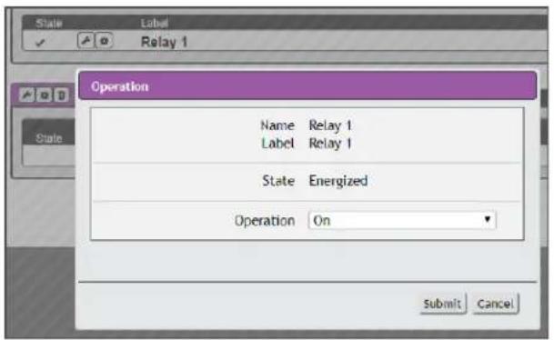
To configure the relay manual control:
- Click on the Setting icon.
- Change Operation to the desired relay condition: On (Energized); Off (Deenergized).
NOTE: The State label describes the current state of the relay.
- Click Submit to commit the change.
Alarms & Warnings
The Alarms & Warnings section allows you to establish alarm or warning conditions (events) for each sensor reading. Events are triggered when a measurement exceeds a user-defined threshold, either going above the threshold (high-trip) or below it (low-trip). Events are displayed in different sections, based on the device or measurement the event is associated with. Each event can have one or more actions to be taken when the event occurs.
Figure 3.4 Alarms & Warnings Page
![Sensors System Help Log In A 2 0 Alarms & Warnings State Label Trigger Severity Type Value Valid Time Notify Watchdog 15 ✓ ✓ ✓ Geist WD15 Temp Sensor ✓ ✓ ✓ SRT Temperature Alarm High 8.00 — [0] Temperature Alarm High 60.00 — [0]](/content/2026/05/950039/images/9e0e8255262fd81aa2afcfa46dfbe6770fe973084a347ed387fe944abf61c4f0.jpg)
Table 3.2 Alarms & Warnings Descriptions
| NAME ICON DESCRIPTION | ||
| State of each event | No Icon Empty if there is | no alert condition. |
| [SDCK] | This symbol indicates that this particular warning event has been tripped. A tripped warning event displays in orange. | |
| [XSBX] | This symbol indicates that this particular alarm event has been tripped. A tripped alarm event displays in red. | |
 | This symbol indicates that the event has been acknowledged by a user after it was tripped. This condition remains until the event criteria returns to normal, for example, a measurement ceases to exceed the trigger threshold for this event. | |
| Configuration | [7YCO] | Adds new alarms and warnings. |
| [4BDX] | Modifies existing alarms and warnings. | |
| [TBXX] | Delete existing alarms and warnings. | |
| Notification | [XHSW] | When an alarm or warning event occurs, you can click on this symbol to acknowledge the event and stop the unit from sending any more notifications about it.NOTE: Clicking this symbol does not clear the alarm or warning event, it just stops the notifications from repeating. |
| Details n/a Displays the conditions for the alarm and warning settings. | ||
To add a new alarm or warning event:
- Click the Add/Modify alarms and warnings icon and configure the desired conditions for this event as follows:
Figure 3.5 Adding New Alarm or Warning Events

a. From the drop-down lists, select the name of the phase or circuit, the trigger measurement, the severity and the type.
NOTE: High trips if the measurement goes above the threshold and low trips if the measurement goes below the threshold.
b. Enter the desired threshold value (any number between -999.0 \~ 999.0).
c. Enter the desired clear delay time (in seconds). Any value other than 0 means once this event is tripped, the measurement must return to normal for this many seconds before the event will clear and reset. Clear Delay can be up to 14400 seconds (4 hours).
d. Enter the desired trip delay time (in seconds). Any value other than 0 means that the measurement must exceed the threshold for this many seconds before the event will be tripped. Trip delay can be up to 14400 seconds (4 hours).
e. Enable or disable the latching mode. If enabled, this event and its associated actions remain active until the event is acknowledged, even if the measurement subsequently returns to normal.
f. Click the Add icon to create a new time range. Specify days/hour range to send alert notifications when this alarm or warning event occurs.
Figure 3.6 Add Alert Notification Target

g. Click the Add icon to add a Target and then specify the email address or SNMP manager to which notifications should be sent when the event is tripped. Enter the delay and repeat values (discussed in the following paragraphs) and click Save.
NOTE: Target Delays and Repeats are shared across all alarms. If multiple Delay and/or Repeat values are needed for specific Targets, each one must be added to the Target list and then the appropriate Enabled box checked on each alarm.
- Delay: determines how long this event must remain tripped for before this action's first notification is sent. This is different from the Trip Delay above. Trip Delay determines how long the threshold value has to be exceeded before the event itself is tripped. This delay determines how long the event must remain tripped before this action occurs. Delay can be up to 14400 seconds (4 hours). A Delay of 0 will send the notification immediately.
-
Repeat: determines whether multiple notifications will be sent for this event action. Repeat notifications are sent at the specified intervals until the event is acknowledged, or until the event is cleared and reset. The Repeat interval can be up to 14400 seconds (4 hours). A Repeat of O disables this feature, and only one notification will be sent.
-
Click Save to save this notification action.
NOTE: More than one action can be set for an alarm or warning; to add multiple actions, just click the Add icon again and set each one as desired. Each alert can have up to 32 actions associated with it.
To change an existing alarm or warning event:
- Click the Modify icon next to the alarm or warning event you wish to change.
Figure 3.7 Modify Action

- Modify the specific settings as needed and click Save.
- After an action is added, it has a checkbox in the Enabled column on the far left. By default, when an action is added, it is unchecked (disabled). Click the checkbox to enable it and select to turn different actions on and off for testing.
To delete an existing alarm or warning event:
- Click the Delete icon next to the alarm or warning event you wish to change.
- Click Delete and Save to confirm.
Logging
The Logging page allows you to download the historical data recorded by the unit. Recorded data is available for download in Comma-Separated Values (CSV) or JavaScript Object Notation (JSON) file types. Data is written to the log every 60 seconds; however, all sensor data used by the real-time display and alarm functions is read at least once every 5 seconds.
Figure 3.8 Logging Page

To download the data log:
- Right-click on the desired data type, JSON or CSV.
-
Choose Save link as.....
-
Follow the Save link prompt.
To clear the data log:
- Click the Clear the Log button.
NOTE: All previously recorded data will be deleted.
- Click OK to confirm the deletion.
Data Graph
The Data Graph page allows you to display the historical data from the data log in graph format.
Figure 3.9 Data Graph

line
| State | Name | Temperature (F) | Humidity (%) | Dewpoint (F) | |-------|------|-----------------|--------------|--------------| | ○ | Geist WD100 | 74.85 | 37 | 46.85 |To configure a graph:
- Click to highlight the desired measurement.
- Choose the Time Range (15 minutes to 30 days).
- Click the Display/Refresh button to display changes.
3.1.2 System tab
The System tab is used to access/configure the users, network, web server, time, email, SNMP, Syslog, Admin, Locale, Utilities and Help Information.
Users
The Users account page in the System menu allows you to manage or restrict access to the unit's features by creating accounts for different users.
Figure 3.10 User Account Page

Table 3.3 User Account Icon Descriptions
| NUMBER DESCRIPTION | |
| 1 Add new target user account | |
| 2 Modify existing target user account | |
| 3 Delete existing target user account |
NOTE: Only an Administrator-level account can add, modify or delete users. Control-level and View-Only accounts can change their own passwords via the Modify icon, but cannot add or delete accounts, or modify other accounts. The Guest account cannot add, modify or delete any account, not even itself.
To add or modify a user account:
- Click the Add or Modify User icon.
Figure 3.11 Add or Modify a User Account
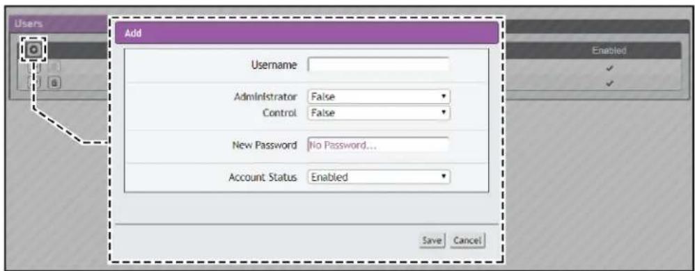
- Create or modify the account information as follows:
a. Enter the username of this account. Usernames can be up to 24 characters long, are case sensitive and cannot contain spaces or any of the following characters: \$&<>[] {}"+%@/;=?|^\~".
NOTE: An account's username cannot be changed after the account is created.
b. Select True in the Administrator field to allow Administrator-level access to the unit and change any settings.
c. Select True to allow Control-level access to this account.
NOTE: Setting Administrator to True automatically sets Control to True as well. Setting this to False makes the account a View-Only account.
d. Enter a new password. Account passwords can be up to 24 characters long, are case sensitive and cannot contain spaces.
e. Set the account status to Enabled or Disabled. Disabling an account prevents it from being used to log in, but does not delete it from the account list.
- Click the Save button when finished.
Account Types:
- Administrator: Administrator accounts (accounts with both Administrator and Control authority set to True) have full control over all available functions and settings on the device, including the ability to modify System settings and add, modify or delete other users' accounts.
- Control: Control accounts (accounts with only Control set to True) have control over all settings pertaining to the device's sensors. They can add, modify or delete alarms and warning events and notification actions, and can change the names or labels of the device and its sensors. Control accounts cannot, however, modify system settings or make changes to other users' accounts.
- View: If both Administrator and Control are set to False, the account is a View-Only account. The only changes a View-Only account is permitted to make are changing their own account's password, and changing the preferred language for their own account. View-Only accounts cannot change any device or system settings.
- Guest: Anyone who brings up the unit's web page without logging in will automatically be viewing the unit as Guest. By default, the Guest account is a View-Only account, and cannot make changes to any settings, although the Administrator can elevate the Guest account to Control-level access if desired, allowing anyone to make changes to names, labels, alarm events and notifications, without logging in. The Guest account cannot be deleted, but can be disabled to require logging in to view system status.
Figure 3.12 Change User Password Page

- Edit User: Once a user has logged in to their account, they can change their password or language preference by clicking their username (located next to the Log Out hyperlink at the upper right corner of the web page).
Network
The unit's network configuration is performed on the Network tab of the System menu. Settings pertaining to the unit's network connection are:
- Hostname: The host name can be used as a method for device identification on the network.
- Interfaces: Used to configure the IP address of the device, enable/disable DHCP and to view Link State and Uptime.
- Ports: Used to view and/or modify Ethernet port settings on the device.
- Routes: Displays configured routes and is also where you will set your Gateway address for the device. Default routes are distinguished by a destination of 0.0.0.0 or :, with a prefix of 0 and interface of all. Only one default route can exist for IPv4 and one for IPv6.
- DNS: Allows the unit to resolve host names for email, NTP and SNMP servers.
Figure 3.13 Network Configuration Page

To edit the interfaces' parameters:
- Click the Modify icon and modify the following desired fields:
a. Label - Changes the desired name of the selected interface.
b. DHCP - Enables/disables DHCP on the selected interface. If only one interface is available, disabling the interface restricts access to the device requiring a network reset.
- Click Save.
NOTE: Any changes made to the network interface settings take effect once the Save button is clicked. If you change the IP address, it appears as if the unit is no longer responding because the browser is not able to reload the web page. Close the browser window and enter the new IP address into the browser's address bar to make the unit accessible.
To modify an existing IP address:
- Click the Modify icon and edit the IP Address and Prefix/Subnet Mask fields as needed.
- Click Save.
To modify an existing route:
- Click the Modify icon and edit the desired fields.
- Click Save.
To add a new DNS Server Address:
- Click the Add icon and enter the IP of the desired DNS server. (Up to two DNS servers can be added.)
- Click Save.
To modify an existing DNS Server Address:
- Click the Modify icon and edit the DNS Server Address field as required.
- Click Save.
Web Server
The unit's Web Server configuration can be updated on the Web Server tab of the System menu.
Figure 3.14 HTTP Configuration Page

- HTTP Interface: Enables/disables access via HTTP. HTTPS interface will always be enabled. Available options are: Enabled or Disabled. It is not possible to disable the web interface completely.
- HTTP/HTTPS Server Port: Allows you to change the TCP ports which the HTTP and HTTPS services listen to for incoming connections. The defaults are port 80 for HTTP and 443 for HTTPS.
Time
The system clock is set on the System-Time page. The unit comes preconfigured with the Primary NTP Server pool.ntp.org time servers and is set to the Western Europe Time Zone (00:00 UTC). Should a local time server be preferred, enter its UTC offset or a local time server into the UTC Offset box and click the Save button. The unit attempts to contact the time servers during boot up and periodically while running. All log time stamps will present time as the number of seconds since the unit was powered up until a time server is contacted or the system clock is manually set.
Figure 3.15 NTP Clock Setting

To manually set the system clock:
- From the Mode field, click the drop-down text box and select Manual.
- Enter the Date and Time in the following format: YYYY-MM-DD hh:mm:ss, using military time (2400 hours).
- Click Save when done.
NOTE: Daylight Saving Time (DST) is supported and can be changed in the Daylight Saving Time box.
The unit is capable of sending email notifications to up to five email addresses when an alarm or warning event occurs.
The SSL can be enabled or disabled. If you select Enabled, the unit attempts to connect to the server using a fully-encrypted TLS/SSL connection. Only fully-encrypted sessions are supported; the "StartTLS" method, where the session starts out as unencrypted and then switches to encrypted during the session, is not supported. If using a service that utilizes StartTLS, such as Office 365, leave the Disabled option selected.
Figure 3.16 Email Configuration Page

To configure the unit to access the mail server to send emails:
- Enter the name or IP address of a suitable SMTP or ESMTP server.
- Enter the TCP port which the SMTP Server uses to provide mail services.
NOTE: Typical values are port 25 for an unencrypted connection, or port 465 and 587 for a TLS/SSL-encrypted connection, but these may vary depending on the mail server's configuration.
- Select to enable or disable SSL.
- In the "From" Email Address field, enter the address the unit's emails should appear to come from.
NOTE: Many hosted email services, such as Gmail, require this to be the email account of a valid user.
- Enter the username and password credentials for the email server. If your server does not require authentication (open relay), these can be blank.
Microsoft Exchange servers must be set to allow SMTP relay from the IP address of the unit. In addition, the Exchange server must be set to allow "Basic Authentication", to allow the unit to log in using the AUTH LOGIN method to send its login credentials. Other methods, such as AUTH PLAIN, AUTH MD5 and so on, are not supported.
To add or modify a target email address:
- Click on the Add or Modify icon.
- Enter the email address and click Save.
To delete a target email address:
- Click on the Delete icon next to the address you wish to delete.
- Click the Delete button on the pop-up window to confirm.
To send a test email:
- Click on the Test Email (Envelope) icon next to the address you wish to test.
- A pop-up window indicates the test email is being sent. Click OK.
Simple Network Management Protocol (SNMP)
SNMP can be used to monitor the unit's measurements and status, if desired. SNMP v1, v2c and v3 are supported. In addition, alarm traps can be sent to up to two IP addresses.
Figure 3.17 SNMP Configuration Page

The SNMP-V1/V2c and SNMP-V3 Service can be enabled or disabled independently as desired. The service normally listens for data-read requests (GET requests) on Port 161, which is the usual default for SNMP services. This can also be changed if desired.
The Management Information Base (MIB) can be downloaded from the unit, if needed, via the MIB link at the top of the web page. Clicking this link downloads a .ZIP archive containing both the MIB file itself, and a CSV-formatted spreadsheet that describes the available OIDs in a human-readable form to assist you in setting up your SNMP manager to read data from the unit.
Figure 3.18 SNMP Users Configuration Page

The Users section allows you to configure the various Read, Write and Trap communities for SNMP services. You can also configure or modify the authentication types and encryption methods for the SNMP v3 using the Modify icon.
Figure 3.19 SNMP Traps Configuration Page

Traps allows you to define the IP addresses and SNMP types that will receive the traps you send.
Figure 3.20 SNMP Traps/Types IP Configuration Page

To configure a trap destination:
- Locate the Traps section of the SNMP page, and click on the Add icon.
- Enter the IP address (to send the trap to) in the Host field and change the Port number, if required.
- Select the trap version to be used (v1, v2c, or v3), and click Save.
A test trap can be sent by clicking on the Test icon next to the Host IP address. Trap settings can also be updated/changed by clicking the Modify icon next to the Host IP address.
Syslog
Syslog data can be captured remotely, but must first be set up and enabled via the Syslog page.
NOTE: This function is primarily used for diagnostic purposes, and should normally be Disabled unless advised to enable it by Vertiv technical support for troubleshooting a specific issue.
Figure 3.21 Syslog Configuration Page

Admin
The Admin page allows the administrator of the device to save their contact information along with the device description and location. Once the information is saved by an administrator, other (non-administrator) users can view the information. Also, the system label can be modified on this page. This label is typically shown in the title bar of the web browser's window, and/or on the browser tab(s) currently viewing the device.
NOTE: This information is strictly for the users' and administrator's convenience. The unit will not attempt to send emails to the "Administrator Email" address and this address cannot be chosen as the target of an event action when configuring an alarm or warning event.
Figure 3.22 Admin Configuration Page

Locale
The Locale page sets the default language and temperature units for the device. These settings become the default viewing options for the device, although individual users can change these options for their own accounts. The Guest account is only able to view the device with the options set here.
Figure 3.23 Locale Configuration Page

Utilities
The Utilities page in the System menu provides the ability to restore defaults, reboot the communication system and perform firmware updates.
The Restore Defaults section allows you to restore the unit's settings to the factory defaults. There are two options:
- All Settings: erases all of the unit's settings, including all network and user accounts' settings, effectively reverting the entire unit back to its original out-of-the-box state.
- All Non-Network Settings: erases all settings except the network and user accounts.
Figure 3.24 Restore Default Page

The Reboot section allows you to perform a system reboot. This function does not affect power delivery to connected equipment.
Figure 3.25 Reboot Page

The Firmware Update section is used to load firmware updates into the unit. Firmware updates, when available, can be found on the Vertiv website, http://www.vertivco.com/. You can also subscribe to a mailing list, to be notified when firmware updates become available.
Figure 3.26 Firmware Update Page

Firmware updates typically come in a .ZIP archive file. The fie contains several files, including the firmware package itself, a copy of the SNMP MIB, a "readme" text file explaining how to install the firmware, and various other support files as needed. Be sure to un-ZIP the archive and follow the included instructions.
Help Info page
The Info page displays the unit's current configuration information, including the device serial and model number, part number, the type of IMD installed, the unit's current firmware and GUI version, MAC address and host name. The manufacturer website, support website, email and support telephone numbers are also listed on the Info page.
Figure 3.27 Info Page

This page intentionally left blank
4 APPENDICES
Appendix A: Technical Support
A.1 Service and Maintenance
No service or maintenance is required. Do not attempt to open the Watchdog 100 or you may void the warranty. There are no serviceable parts inside the Watchdog 100. It is recommended that power be removed from the unit before installing or removing any equipment.
A.2 Technical Support Contact Information
Technical support can be found at www.VertivCo.com/support.
Americas:
• Website: www.VertivCo.com/geist
- Email: support@VertivCo.com
• Telephone: 1-888-630-4445
Europe and Middle East:
• Technical Support: www.VertivCo.com/en-emea/support
- Email: eoc@VertivCo.com
• Telephone: 1-800-1155-4499
• From within the UK 0845 026 3853
• From abroad +44 845 026 3853
Asia:
• English: 1-888-630-4445 (US number)
• Chinese: +86 755 8663 9505
Appendix B: Using Microsoft Exchange as an SMTP Server
If your facility uses a Microsoft Exchange email server, it can be used by the Watchdog 100 to send Alarm and Warning notification emails if desired. However, the Exchange server may need to be configured to allow SMTP connections from the unit first, as later version of Exchange often have SMTP services or basic authentication disabled by default. If you encounter difficulties in getting your Watchdog 100 to send emails through your Exchange server, the following notes may be helpful in resolving the problem.
NOTE: These suggestions only apply if you are using your own, physical Exchange server! Microsoft's hosted "Office365" service is not compatible with the Watchdog 100 using firmware versions prior to v3.0.0, as Office365 requires a StartTLS connection. Firmware versions 3.0.0 and beyond have support for StartTLS and are compatible with Office365.
First, since the Watchdog 100 cannot use IMAP or Microsoft's proprietary MAPI/RPC Exchange/Outlook protocols to send messages, you will need to enable SMTP by setting up an "SMTP Send Connector" in the Exchange server. More information on setting up an SMTP Send Connector in Exchange can be found at this Microsoft TechNet article: http://technet.microsoft.com/en-us/library/aa997285.aspx.
Next: Your Exchange server may also need to be configured to allow messages to be “relayed” from the monitoring unit. Typically, this will involve turning on the “Reroute incoming SMTP mail” option in the Exchange server’s Routing properties, then adding the Watchdog 100’s IP address as a domain which is permitted to relay mail through the Exchange server. More information about enabling and configuring SMTP relaying in Exchange can be found at this Microsoft TechNet article: http://technet.microsoft.com/en-us/library/dd277329.aspx.
The SMTP "AUTH PLAIN" and "AUTH LOGIN" authentication methods (also known as "Basic Authentication) for logging in to the server are often no longer enabled by default in Exchange; only Microsoft's proprietary NTLM authentication method is enabled.
To re-enable the AUTH LOGIN method:
- In the Exchange console select Server Configuration - Hub Transport.
- Right-click the client server, and select Properties.
- Select the Authentication Tab and click the Basic Authentication checkbox.
- Deselect the Offer Basic only after TLS checkbox.
- Click Save and then click Exit.
NOTE: You may need to restart the Exchange service after making these changes.
Finally, once you have enabled SMTP, relaying, and the AUTH LOGIN Basic Authentication method, you may also need to create a user account specifically for the Watchdog 100 to log into. If you have already created an account prior to enabling the SMTP Send Connector, or you are trying to use an already-existing account created for another user, probably did not properly inherit the new permissions when you enabled them as above. This tends to happen more often on Exchange servers that have been upgraded since the account(s) you are trying to use were first created, but can sometimes happen with accounts when new connectors and plug-ins are added regardless of the Exchange version. Delete the user account, then create a new one for the monitoring unit to use, and the new account should inherit the SMTP authentication and mail-relaying permissions correctly.
If none of the above suggestions succeed in allowing your Vertiv Watchdog 100 to send mail through your Exchange server, then you may need to contact Microsoft's technical support for further assistance in configuring your Exchange server to allow SMTP emails to be sent from a 3rd-party, non-Windows device through your network.
Appendix C: Product Specific Safety Notices
C.1 General Safety
Safety is a serious matter and all precautions should to taken to guarantee a safe work and operational environment. General safety precautions must be observed during all aspects of operation, service, and repair of equipment described in this document. Failure to comply with the safety warnings, procedures and guidelines as presented in this document is in violation of the safety standards of design, manufacture, and intended use of this equipment.
You are responsible for following the safety guidelines and warnings presented in this document for this equipment. Individuals using or maintaining Vertiv product(s) are expected to follow all the noted warnings and safety precautions necessary for safe operation of the equipment in your environment. Vertiv assumes no liability for failure to comply with these requirements.
C.2 Live Circuits Safety

WARNING! DANGER: HAZARDOUS VOLTAGE, CURRENT, AND ENERGY LEVELS ARE PRESENT IN THIS PRODUCT. POWER SWITCHED CIRCUITS CAN HAVE HAZARDOUS VOLTAGES PRESENT EVEN WHEN THE SWITCH IS IN THE OFF POSITION. DO NOT OPERATE THE PRODUCT WITH ANY COVER PLATE REMOVED. ALWAYS MAKE SURE THAT PRODUCT IS FULLY ENCLOSED PRIOR TO USE.
Operating personnel must:
- Not remove equipment covers. Only Vertiv Authorized Service Personnel or other qualified maintenance personnel may remove equipment covers for internal sub-assembly, or component replacement, or any internal adjustment.
- Not replace any equipment component with power applied to the line cord. Under certain conditions, dangerous voltages may exist even with the input power cable disconnected. Any exceptions for 'Hot-Swap' modules will be specifically noted in this product document.
• Always disconnect input power and discharge circuits before touching any sub-assembly of circuit component.
C.3 Equipment Grounding
To minimize shock hazard, the equipment chassis and enclosure must be connected to an electrical earth ground. The input power cable must be either plugged into an industry electrical code compatible receptacle or wired directly into an electrical code compatible interface. The equipment earth ground wire (typically green) must be firmly connected to the facility electrical safety ground. The mating electrical interface to this equipment must comply with International Electromechanical Commission (IEC) standards.
C.4 Electrostatic Discharge
Vertiv strongly recommends that an anti-static precautions be taken when installing, removing, or working on and around static sensitivity equipment. Industry approved anti-static devices such as wrist and heel straps, in conjunction with conductive foam pads, should be available and implemented only after verifying that they are in good working condition.
Electronic components such as memory modules, circuit boards, and LED displays, are sensitivity to Electro-Static Discharge (ESD). Handling of such components should be done only after proper anti-static workspace conditions have been established. Any static producing packing materials such as plastic, Styrofoam, and some cardboards, should be removed and discarded in a timely manner.
C.5 Explosive Environment
Do not operate this equipment in the presence of flammable gases or fumes. Operation of any electrical equipment in such an environment constitutes a definite safety hazard.
C.6 Servicing and Adjustments
Do not attempt to service this equipment, there are no field serviceable parts or sub-assemblies. Any adjustments should be made by authorized service personnel only.
C.7 Repairs and Modifications
Because of the danger of electrocution and/or severe health hazard, do not install substitute parts or perform any unauthorized modifications of this equipment. It is best to contact Vertiv for Warranty and Repair Service to ensure that safety features are maintained.

VERTIV™

VERTIV™
VertivCo.com | Vertiv Headquarters, 1050 Dearborn Drive, Columbus, OH, 43085, USA
© 2019 Vertiv Co. All rights reserved. Vertiv and the Vertiv logo are trademarks or registered trademarks of Vertiv Co. All other names and logos referred to are trade names, trademarks or registered trademarks of their respective owners. While every precaution has been taken to ensure accuracy and completeness herein, Vertiv Co. assumes no responsibility, and disclaims all liability, for damages resulting from use of this information or for any errors or omissions. Specifications are subject to change without notice.
- Technical Support Site
- TABLE OF CONTENTS
- OVERVIEW
- Environmental
- Electrical
- Networking
- Ethernet
- Protocols
- User Interfaces
- Onboard Sensors
- External Sensors
- INSTALLATION
- To install the Watchdog 100:
- Network Setup
- To set up the network for a Windows operating system:
- Regulatory Compliance
- Underwriters Laboratories (UL)
- Federal Communications Commission (FCC)
- RoHS/WEEE
- WEB INTERFACE
- Home Page
- Sensors tab
- Modifying the device label and temperature offset
- Deleting a sensor
- Relay Control
- Relay Contact Ratings
- Relay Configuration
- Relay Labeling and Mode Select
- Alarms & Warnings
- To delete an existing alarm or warning event:
- Logging
- To download the data log:
- Data Graph
- To configure a graph:
- System tab
- Users
- Account Types:
- Network
- Web Server
- Time
- To delete a target email address:
- To send a test email:
- Simple Network Management Protocol (SNMP)
- To configure a trap destination:
- Syslog
- Admin
- Locale
- Utilities
- Help Info page
- APPENDICES
- Appendix A: Technical Support
- A.1 Service and Maintenance
- A.2 Technical Support Contact Information
- Appendix B: Using Microsoft Exchange as an SMTP Server
- To re-enable the AUTH LOGIN method:
- NOTE: You may need to restart the Exchange service after making these changes.
- Appendix C: Product Specific Safety Notices
- C.1 General Safety
- C.2 Live Circuits Safety
- C.3 Equipment Grounding
- C.4 Electrostatic Discharge
- C.5 Explosive Environment
- C.6 Servicing and Adjustments
- C.7 Repairs and Modifications
Brand : Emerson
Model : Watchdog 100
Category : Moniteur environnemental