
RLK16-410B8 - Security Camera REOLINK - Free user manual and instructions
Find the device manual for free RLK16-410B8 REOLINK in PDF.


| Product Type | 16-Channel NVR Kit with 8 Cameras |
| Camera Resolution | 4 Megapixels (2560 x 1440) |
| Supported Channels | 16 channels (NVR) |
| Video Compression | H.265+ |
| Night Vision | Infrared up to 30 meters |
| Storage | Supports up to 2 SATA HDDs (not included) and microSD card (up to 128 GB) |
| Power Supply | PoE (IEEE 802.3af) for cameras; DC 48V for NVR |
| Network Interface | 1 x RJ45 10/100/1000 Mbps (NVR); cameras via PoE |
| Audio | Two-way audio (camera built-in microphone and speaker) |
| Motion Detection | Yes, with adjustable sensitivity and zones |
| Remote Access | Via Reolink App (iOS/Android) and Client Software (Windows/Mac) |
| Email Alerts | Yes, with snapshot attachment |
| FTP Upload | Yes, configurable schedule |
| DDNS Support | Yes (3322.org, DynDNS) |
| NTP Support | Yes, auto time sync |
| Privacy Masking | Yes, multiple zones |
| Maintenance | Clean camera lens with soft, dry cloth; avoid water and solvents |
| Safety Certifications | FCC, RoHS |
| Spare Parts | microSD card, CR2032 battery (for internal RTC) |
| Warranty | 1 year limited warranty |
Frequently Asked Questions - RLK16-410B8 REOLINK
User questions about RLK16-410B8 REOLINK
0 question about this device. Answer the ones you know or ask your own.
Ask a new question about this device
Download the instructions for your Security Camera in PDF format for free! Find your manual RLK16-410B8 - REOLINK and take your electronic device back in hand. On this page are published all the documents necessary for the use of your device. RLK16-410B8 by REOLINK.
USER MANUAL RLK16-410B8 REOLINK
natural_image
Two macOS desktop screens displaying a real estate scene with multiple windows and a building, no visible text or symbols on the devices themselves.User Manual V1.0 (MAC)
4 MegaPixels Network Camera
1080P Network Camera
Reolink Client Software
Thank you for purchasing the Reolink Network Camera.
For the latest User Manual, Product Updates and more information about the products, please visit our website at:
《《“○切天天”吗。钟、双西。天
CAUTION
RISK OF ELECTRIC SHOCK DO NOT OPEN

CAUTION: TO REDUCE THE RICK OF ELECTRIC SHOCK DO NOT REMOVE COVER. NO USER SERVICEABLE PARTS INSIDE. REFER SERVICING TO QUALIFIED SERVICE PERSONNEL.
The lightning flash with arrowhead symbol, within an equilateral triangle, is intended to alert the user to the presence of uninsulated "dangerous voltage" within the products' enclosure that may be of sufficient magnitude to constitute a risk of electric shock.

The exclamation point within an equilateral triangle is intended to alert the user to the presence of important operating and maintenance (servicing) instructions in the literature accompanying the appliance.
WARNING: TO PREVENT FIRE OR SHOCK HAZARD, DO NOT EXPOSE THIS UNIT TO RAIN OR MOISTURE.
CAUTION: TO PREVENT ELECTRIC SHOCK, MATCH WIDE BLADE OF THE PLUG TO THE WIDE SLOT AND FULLY INSERT.
GETTING STARTED

natural_image
Simple icon of an open book inside a blue circle (no text or symbols)We have developed user-friendly products and documentation. You may download the software and manual from B 《《〃○but天天〃吗。¥、双否。大○。

natural_image
Blue circular icon with a white question mark symbol (no text or numbers)If you have any questions, you may refer to 《《“○的文、双西B人。天×B《夕○B乱、○」○×B又

natural_image
Icon of a wrench inside a dark circular background (no text or symbols)If you may need any technical support, please contact us at service@reolink.com or support@reolink.com

natural_image
Simple black download icon with a downward arrow and a curved base (no text or symbols)You may download Firmware from
https://reolink.com/firmware/
FCC Verification
Note: This equipment has been tested and found to comply with the limits for Class B digital device, pursuant to part 15 of the FCC Rules. These limits are designed to provide reasonable protection against harmful interference in a residential installation. This equipment generates, uses and can radiate radio frequency energy and, if not installed and used in accordance with the instructions, may cause harmful interference to radio or television reception, which can be determined by turning the equipment off and on, the user is encouraged to try to correct the interference by one or more of the following measures:
- Reorient or relocate the receiving antenna
- Increase the separation between the equipment and the receiver
- Connect the equipment into an outlet on a circuit different from that to which the receiver is connected
- Consult the dealer or an experienced radio/TV technician for help
These devices comply with part 15 of the FCC Rules. Operation is subject to the following two conditions:
• These devices may not cause harmful interference, and
• These devices must accept any interference received, including interference that may cause undesired operation.
Important Note :
All jurisdictions have specific laws and regulations relating to the use of cameras. Before using any camera for any purpose, it is the buyer's responsibility to be aware of all applicable laws and regulations that prohibit or limit the use of cameras and to comply with the applicable laws and regulations.
FCC Regulation (for USA):
Prohibition against eavesdropping
Except for the operations of law enforcement officers conducted under lawful authority, no person shall use, either directly or indirectly, a device operated pursuant to the provisions of this Part for the purpose of overhearing or recording the private conversations of others unless such use is authorised by all of the parties engaging in the conversation.
WARNING
Modifications not approved by the party responsible for compliance could void user's authority to operate the equipment.
IMPORTANT SAFETY INSTRUCTIONS
- Make sure product is fixed correctly and stable if fastened in place
- Do not operate if wires and terminals are exposed
- Do not cover vents on the side or back of the Camera and allow adequate space for ventilation
RoHS:
This product is fully compliant with the European Union Restriction of the Use of Certain Hazardous Substances in Electrical and Electronic Equipment ("RoHS") Directive (2002/95/EC). The RoHS directive prohibits the sale of electronic equipment containing certain hazardous substances such as lead, cadmium, mercury, and hexavalent chromium, PBB, and PBDE in the European Union.
BATTERY INFORMATION
This product contains a removable battery. If you need to replace or dispose of the internal battery.
The battery is located on the main board of the Camera. It is a primary lithium CR2032 button cell.
To access, remove and/or replace the battery:
- Ensure the Camera is turned OFF. NEVER open the Camera's case while power is connected.
- Remove the five screws holding the cover on the Camera.
- If replacing the battery, ensure that it is an exact match for size, type and capacity.
- Be sure to safely dispose of the battery. The process for battery disposal/recycling varies from location to location, please check with the relevant local authority for method.
BATTERY SAFETY INSTRUCTIONS
- Do NOT attempt to open, puncture, disassemble or modify the battery in any way.
- Do NOT subject it to sudden shock or heat.
- Do NOT dispose of battery in fire.
CONTENTS
Getting Started.... 2
Notice.... 4
Contents.... 5
Connection Diagram 6
Client Software
Install Software.... 7
Live View.... 8
Local Setting.... 11
Device Settings.... 12
Display
OSD.... 13
Mask.... 14
Record
Recording.... 15
Recording Schedule.... 16
Encode
Encode.... 17
Network
Network Status.... 18
Network Settings.... 19
E-mail Setup.... 20
FTP Setup.... 21
DDNS Setup.... 23
NTP Setup.... 24
WIFI Settings.... 25
Other Settings.... 26
28
Alarm
Motion.... 27
Sensitivity 28
Schedule.... 29
Action.... 30
Area.... 31
Device
SD Card.... 32
System
Information.... 33
Date&Time.... 34
DST.... 35
Maintenance.... 36
Reboot.... 37
User
User Manage....38
Optical Zoom.... 39
Image Setting.... 40
Advanced Setting...... 41
Playback.... 42
Warranty Terms & Conditions 43
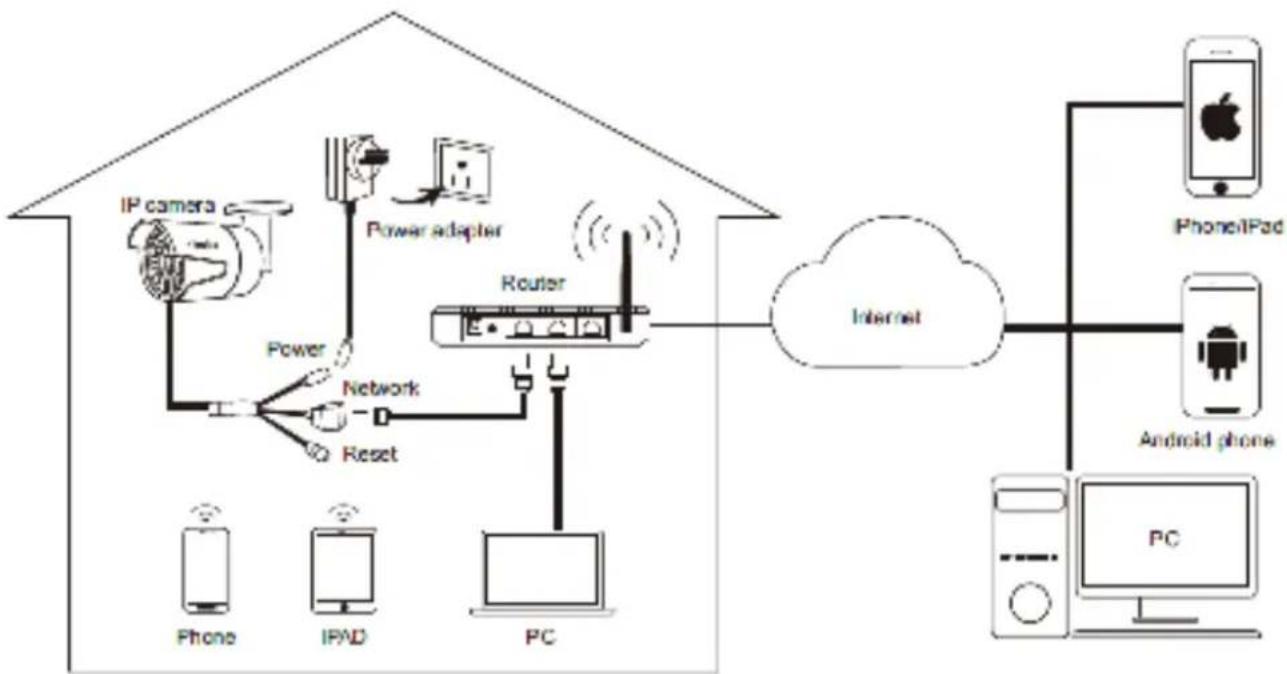
This page shows how Camera connect to the Network System
flowchart
graph TD
    A["IP camera"] -->|Power| B["Router"]
    C["Power adapter"] -->|Power| B
    D["Phone"] -->|Reset| B
    E["IPVD"] -->|Reset| B
    F["PC"] -->|Reset| B
    B --> G["Internet"]
    G --> H["PC"]
    I["IPhone/iPad"] --> J["Android phone"]
    K["Internet"] --> L["PC"]
! Attention: For Initial Setup, connect the camera by network and power cable. Then follow the steps below.
- Connect Network Cable to the Camera, and other end to the POE Switch or Router.
- Connect Power adapter to the camera and turn on the power.
- You may use your Mobile devices or PC to setup the camera.
You may view the camera from local network or Internet after successful set-up.
Reolink Mac Client Software
The Reolink Mac software will allow you to:
• view images from your Camera real-time,
- playback recorded footage,
• copy footage to your local PC and
- adjust settings and configure the Camera.
In fact, the Reolink software is so powerful, you don't need to connect a monitor to the Camera. You only need a computer on the same local network where the Reolink camera is connected.
For quick and easy configuration of the Camera's settings, recording quality and schedule, w suggest to use the remote interface in Reolink.
How to install Reolink MAC Software:
- You need to download Mac client from www.reo-link.com/manual, then you can find the dmg file of the
Reolink client
Mac-ReolinkClient-2.1.6.22.dmg

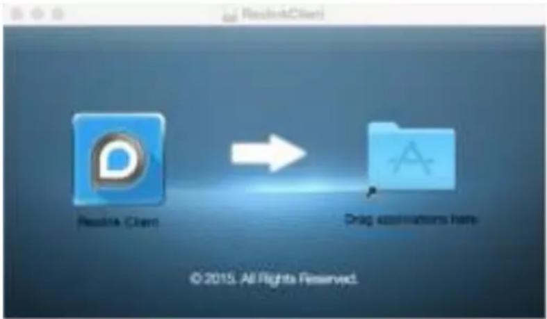
- Click the dmg file, then you will see below popup, drag the Reolink Client application to application folder
flowchart
graph LR
    A[" Reddit Client "] --> B[" Drag destinations file "]
- You can find the Reolink Client from Applications Folder, double click to run the program.
Log on to Reolink
After installing the Software, you will see below screen.
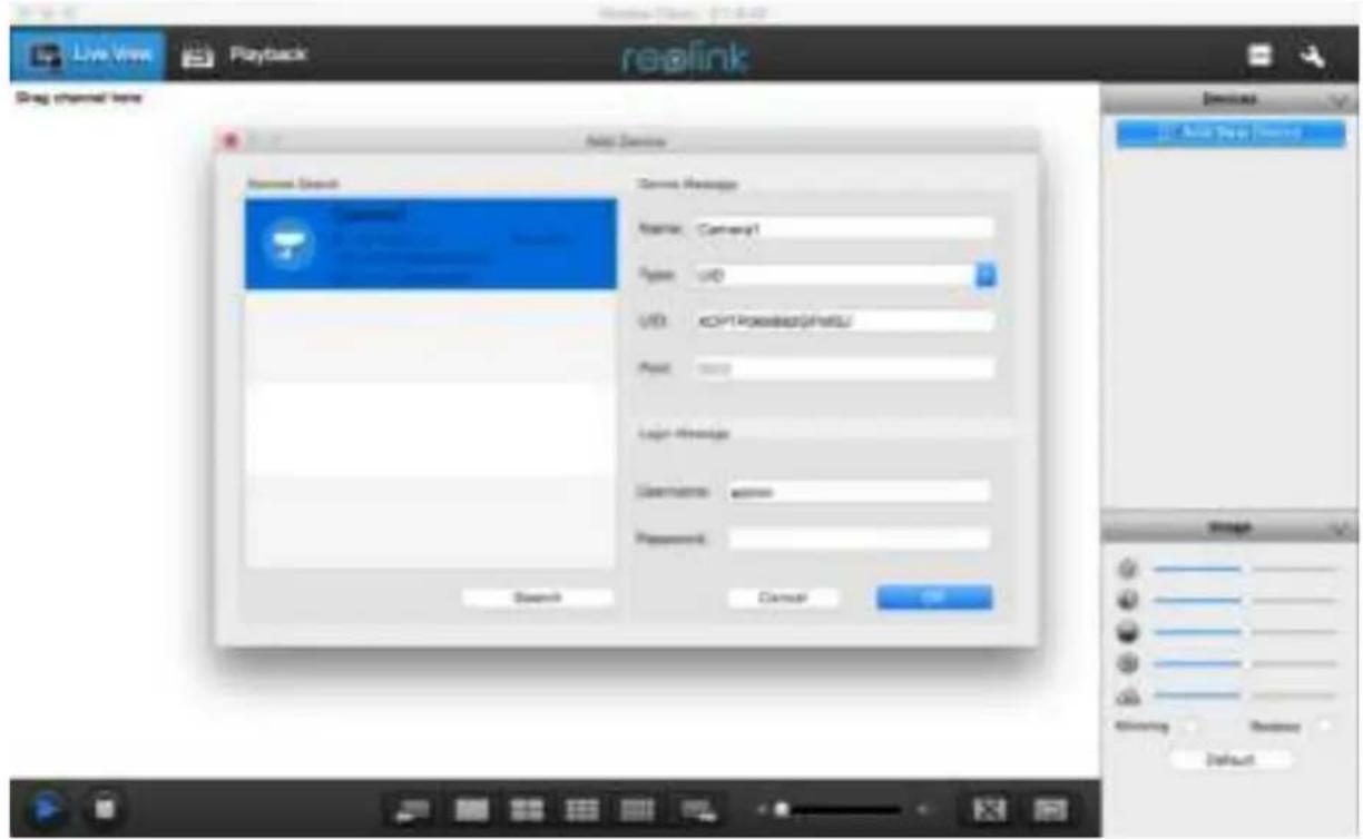
- Click Add Device Button on the top right.
- The LAN device will auto show on the Device Search List or you can Click Search Button.
- Double click the device you want to add then device info will be displayed.
- Input the password(default password is Blank), if you already create password on Reolink App, you need to use the password you created to log in
- Then click OK to Log in .
To connect from your PC to your Camera, make sure your Camera is on and all connections are ok.
IP Address
- If your Camera is in the same LAN network with your PC, the device will auto show on the search list or you can click Search to automatically get the IP address / Camera UID to log in.
- Then, enter your Username (the default of admin is already entered) and Password (default is blank), you need to use the password which you create on Mobile or use default password, then click OK. After a few seconds, you will see your cameras live on your PC.
UID
- If your camera is not in the same LAN network with your PC, you can use UID connect mode.
- You can manually type the UID under the UID QR code which on the body of camera UID field .
- Then, enter your Username (the default of admin is already entered) and Password (default is blank), you need to use the password which you create on Mobile or use default password, then click OK. After a few seconds, you will see your cameras live on your PC.
Using the Live View Screen
Live View is the default mode for the Camera.
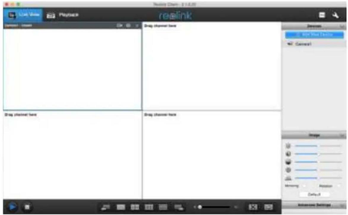
- Live View: Shows the live view of the camera
- Playback: Remotely playback video recorded to Camera or PC or NVR
- CPU: CP U icon will turn from white to Yellow colour when CPU loading is around 100%
- Local Setting: can set the record/Download/Capture path of the file
- Device List : Shows the device connected to the software
- Image Settings: Can set Image parameters
- Advanced Settings : Setting the image night vision performance
- Play / Stop Control: Choose to play or stop the Live videos
- Display Layout : Choose 1/4 and multi-channel view up to 16 Channels
- Previous and Next Page: choose which group of channel to display during multichannel view
- Sound: you may enable/disable the sound and adjust its volume.
- FullScreen : expand the choose screen to full screen
- Extend: you can extend the image to fit your screen setting
More details will be explained in the next pages.
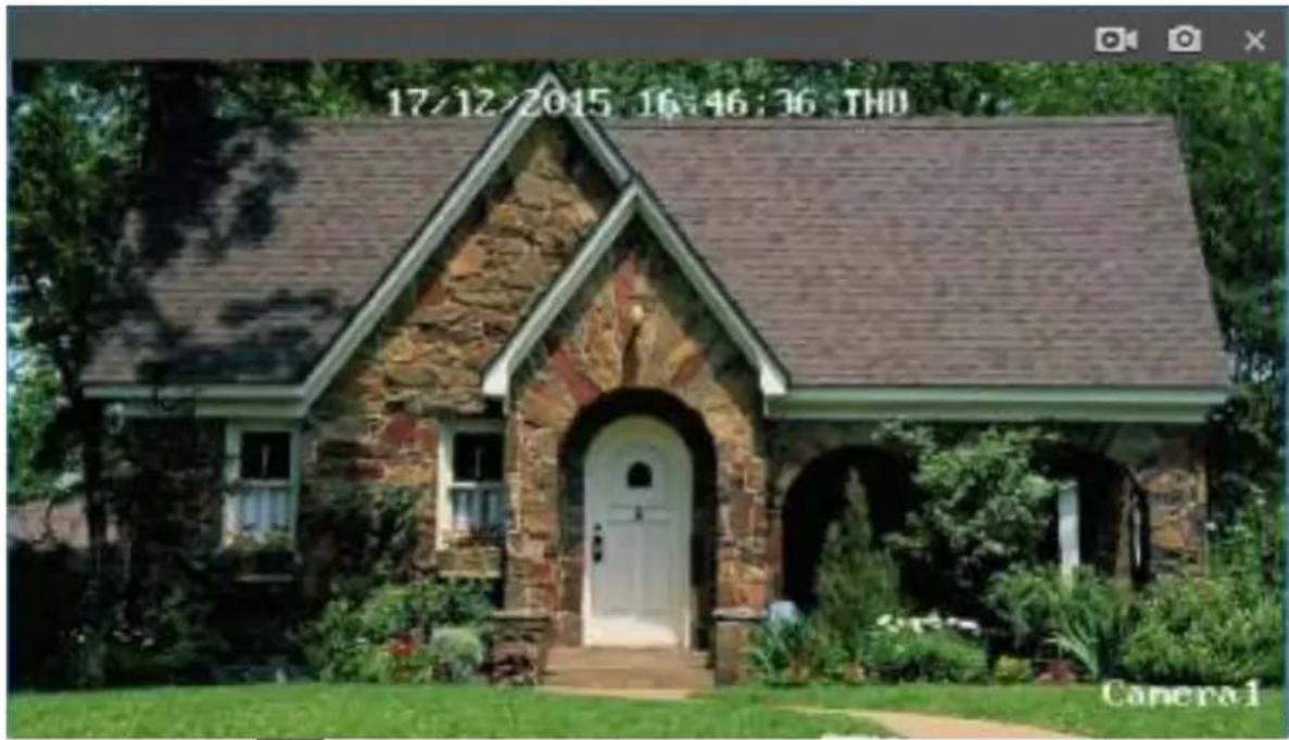
Click
Capture button to take a snapshot of the image
Record Button Manual start record or stop record of the selected channel. During the recording, the record button will turn blue
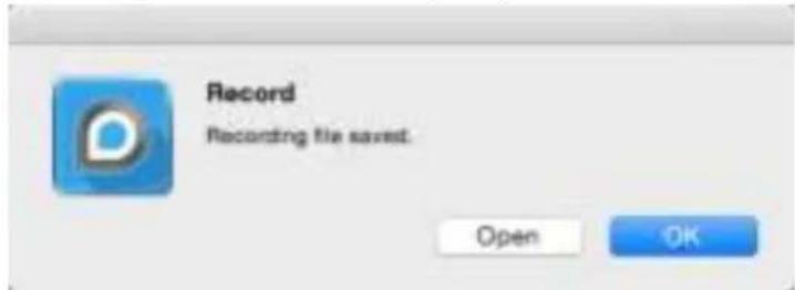
When you click again the record button, the record will stop, it will show below windows that Recoding file saved. Click Open you can find the recorded file.
| Name | ^ | Date Modified | Size |
| 411WS_ch01_20160213_125401.mp4 | Today, 12:54 PM | 3.8 MB | |
| 411WS_ch01_20160213_125415.mp4 | Today, 12:54 PM | 5.2 MB | |
| 411WS_ch01_20160213_125427.mp4 | Today, 12:55 PM | 53.2 MB | |
| 411WS_ch01_20160213_125808.mp4 | Today, 12:58 PM | 1 MB |
Click to stop Live View.
Click Local Settings button on the upper right of the screen. The local Settings screen is where you can customise how ReoLink will store and process footage on the local PC when you download it from the Camera.
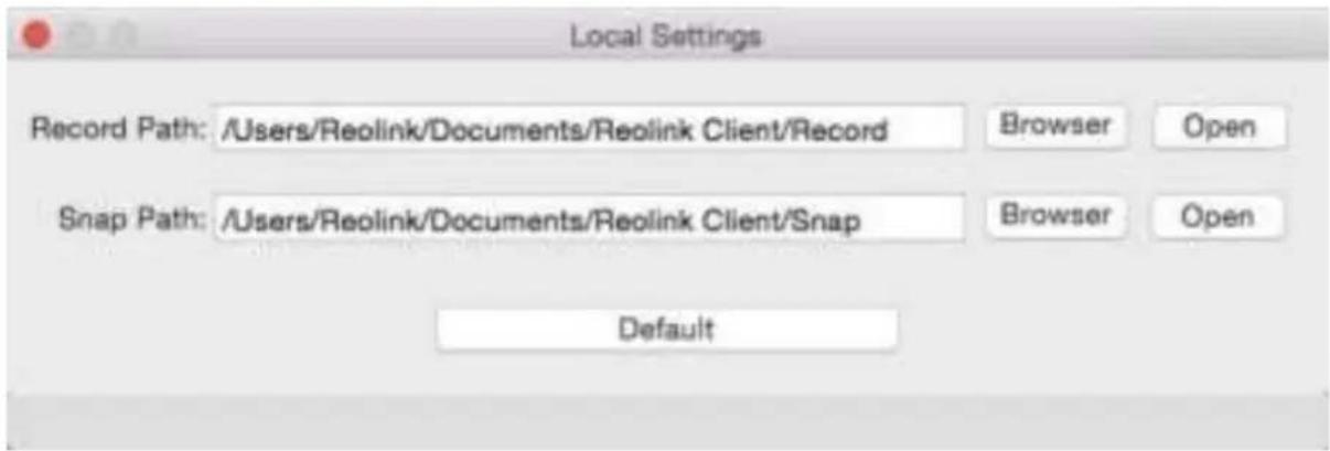
Record Path: Where ReoLink will save recordings if you select Record from the Preview screen.
Capture Path: Where ReoLink will save still images captured using the snapshot function.
You can click browser to set the path your preferred or click open to open the Record / Snap Path.
When you click Default, it will show the above Local setting Path.
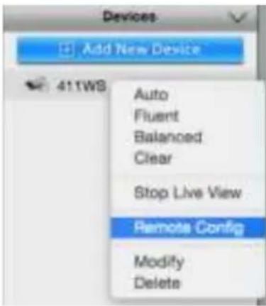
Right Click the Device, it will show the setting window, click the Remote Config, you will see below window and set the the related parameters.
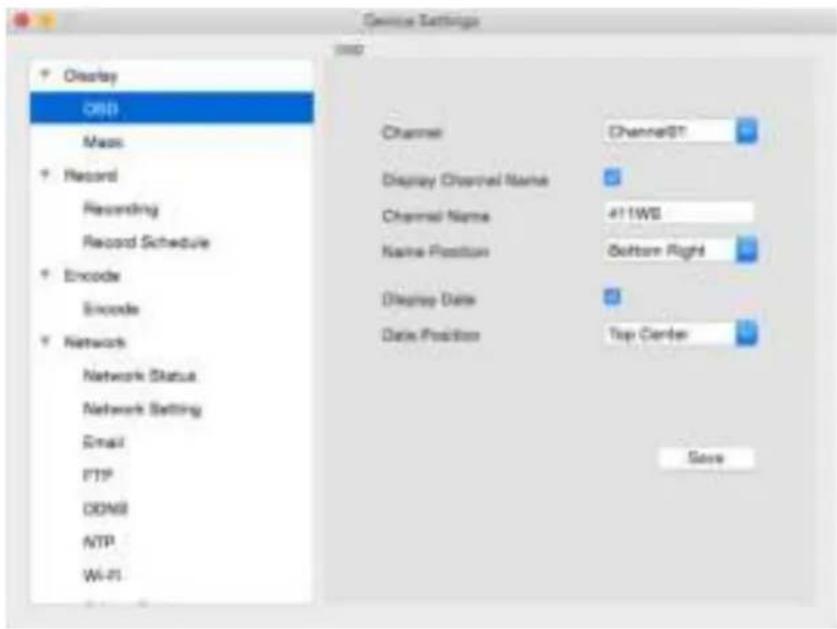
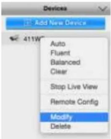
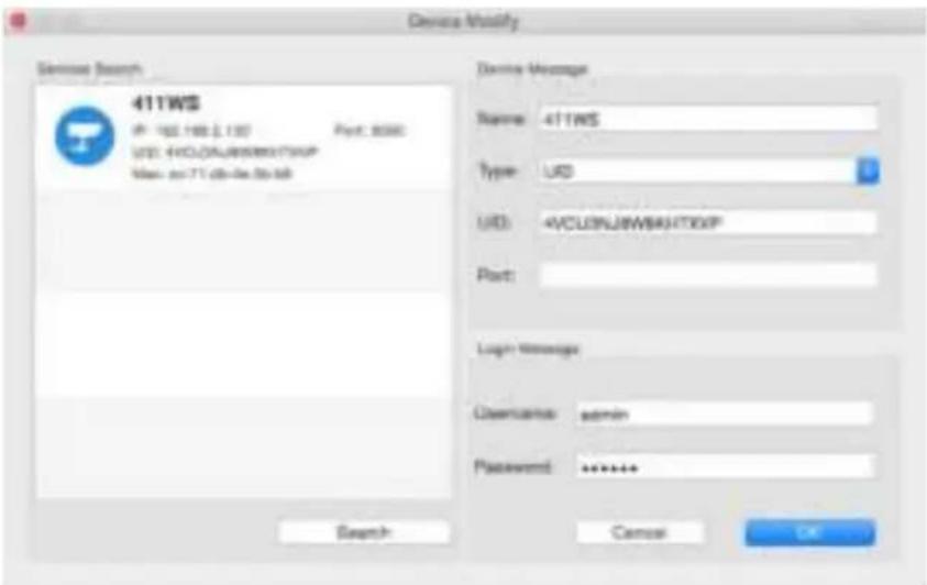
You can click Modify to retype the device username or password if your modify it from other client or Mobile App.
You can also click delete to remove the selected device from the device list.
Click OSD icon, you will see next page
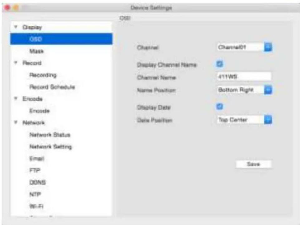
- Channel : Choose the channel you want to setting OSD.
- Channel Name: Enable/Disable channel name, you may also rename the Channel name here.
- Name Position : you may put the Channel name on the upper left, lower left, upper right, lower right, top centre or bottom centre.
- Display Date : Enable or disable to show the date and time on the screen.
- Date Position : you may set the date position here .
Click Save to keep the settings.
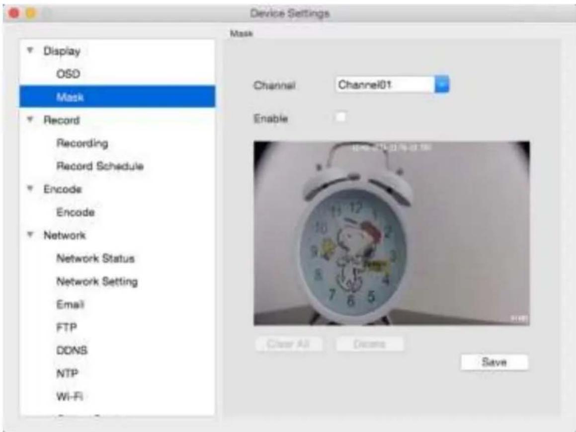
Choose the channel you want to setting. Then click Enable to turn on the masking functions.
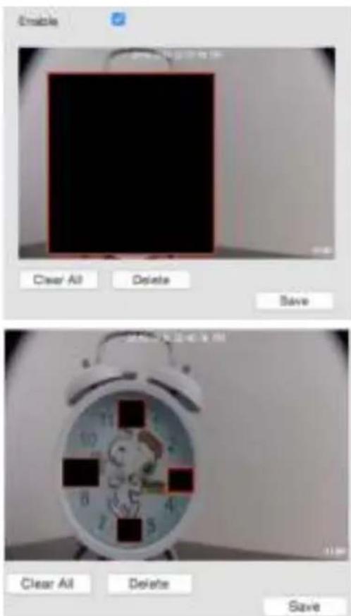
Mask (Setup): use the mouse to create a black privacy overlay which masks part of your images, then click Save. Then on your live view page, will show the black mask also.
If you set more than 1 masks and only want to delete 1 mask, then choose the mask you want delete, then click Delete button and click save.
If you want to delete all the masks, directly click clear All to delete at the mask, then click save.
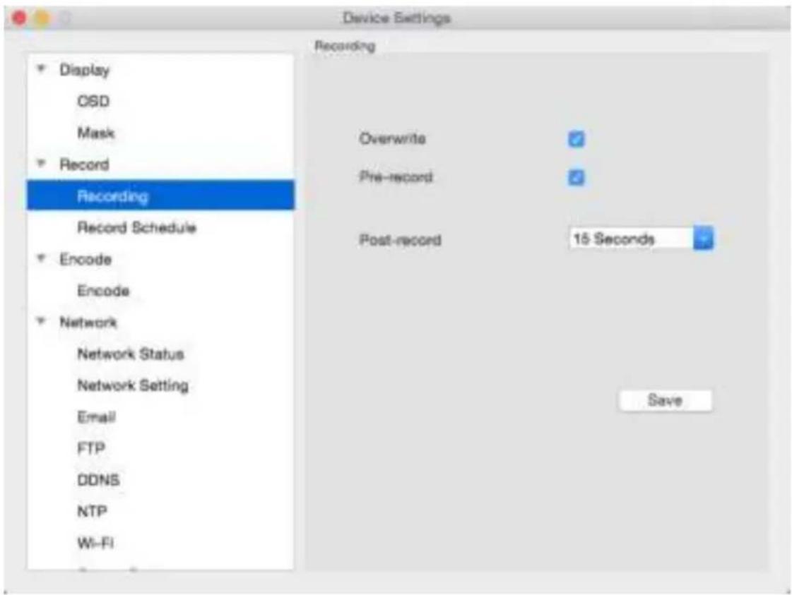
Overwrite When enabled, the SD card will record over the files already stored on the card. The camera will always record over the oldest files on your SD card first.
Pre-record While Pre-Record is enabled, the camera will record a few seconds before an event occurs. Post-record How long after an event occurs that the camera will continue to record.
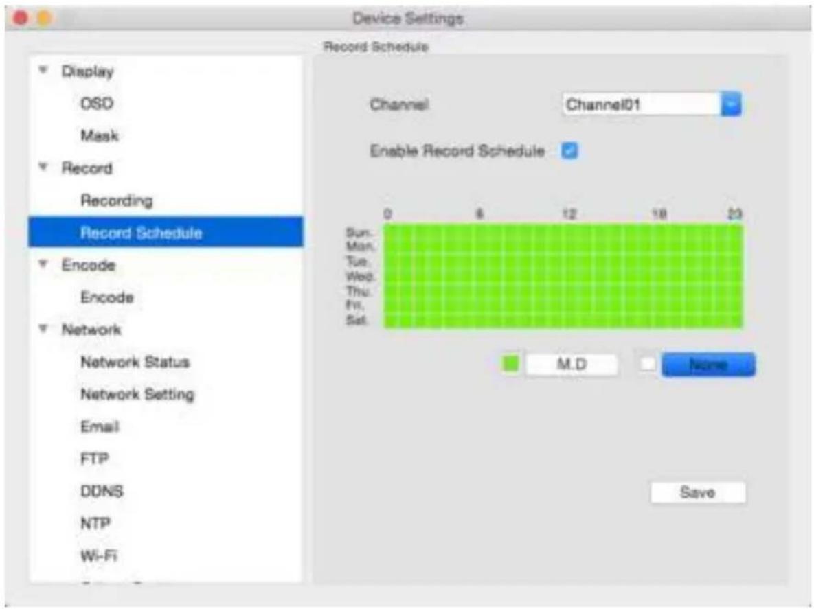
Here you can setting the record schedule for Motion detection on SD Card.
SD card can only storage Motion Detection alarm, it don't support continuous recording.
The SD card will only record when it detects something moving in front of a camera, and will then only record footage from the camera(s) that do detect motion.
Click Enable Record Schedule to turn on the record schedule setting functions.
Green grid means enable Motion detection function
White grid means no recording even motion detection happen
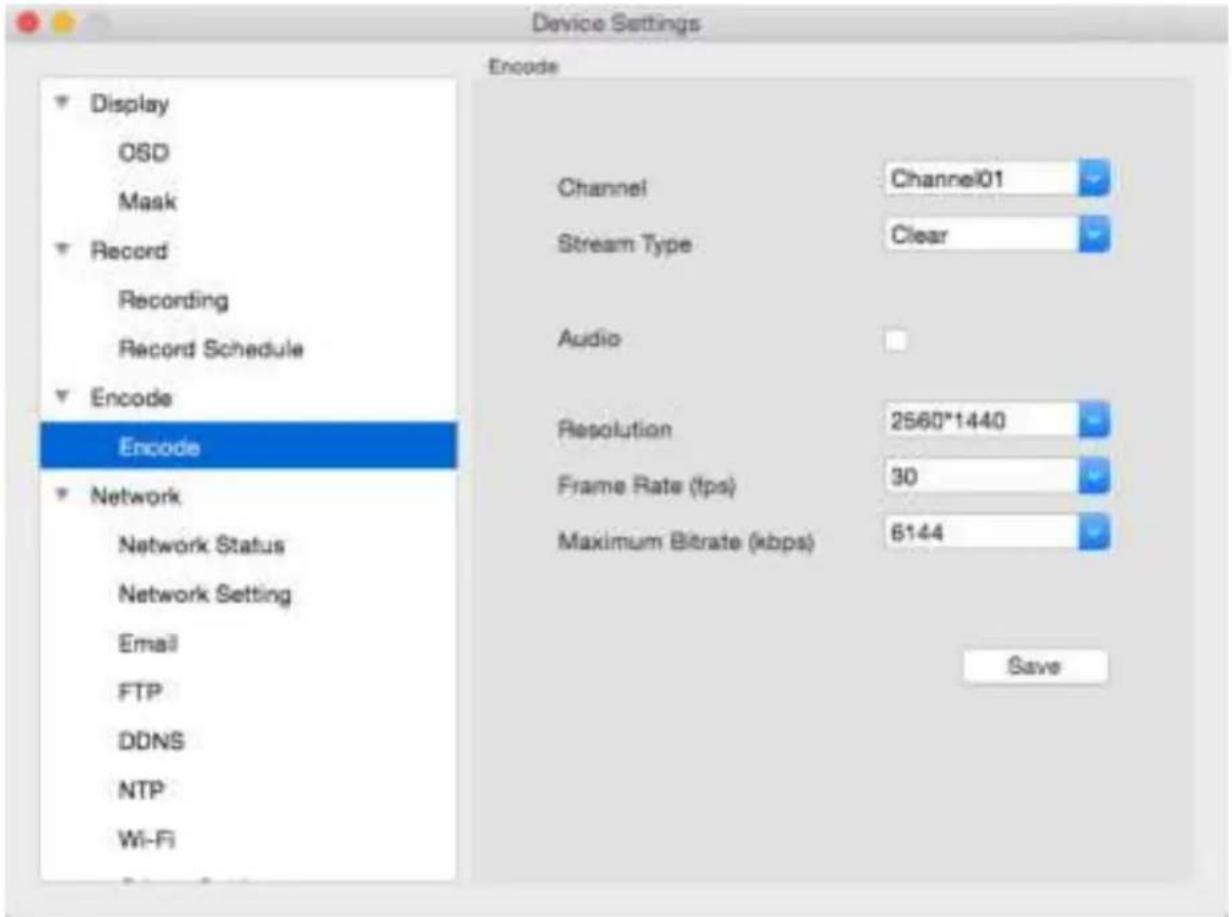
- Stream Type: Whether you're editing the parameters for the mainstream or the sub-stream.
- Clear(Main-Stream): the video feed that the Camera will record and display. This is the higher-quality stream.
- Fluent(Sub-Stream): the video stream that the Camera will send to remote devices via a network or the Internet. It is the lower-quality stream as a reduction in video size makes it easier to send over a network.
• Record Audio: recording with Audio
- Resolution: Tells how many "little dots" are going to make up your image.
- Frame Rate: Tells the number of frames per second (fps) that the Camera will record. Reducing the number of fps will not save hard drive space but potentially improve the data-rate per frame.
- Max. BitRate(Kbps): The actual amount of data that the Camera will use to record video. The higher the bitrate, the more space each recording will take up on the hard disk. Generally speaking, recording encoded at higher bitrates will be of better quality, especially when recording movements.
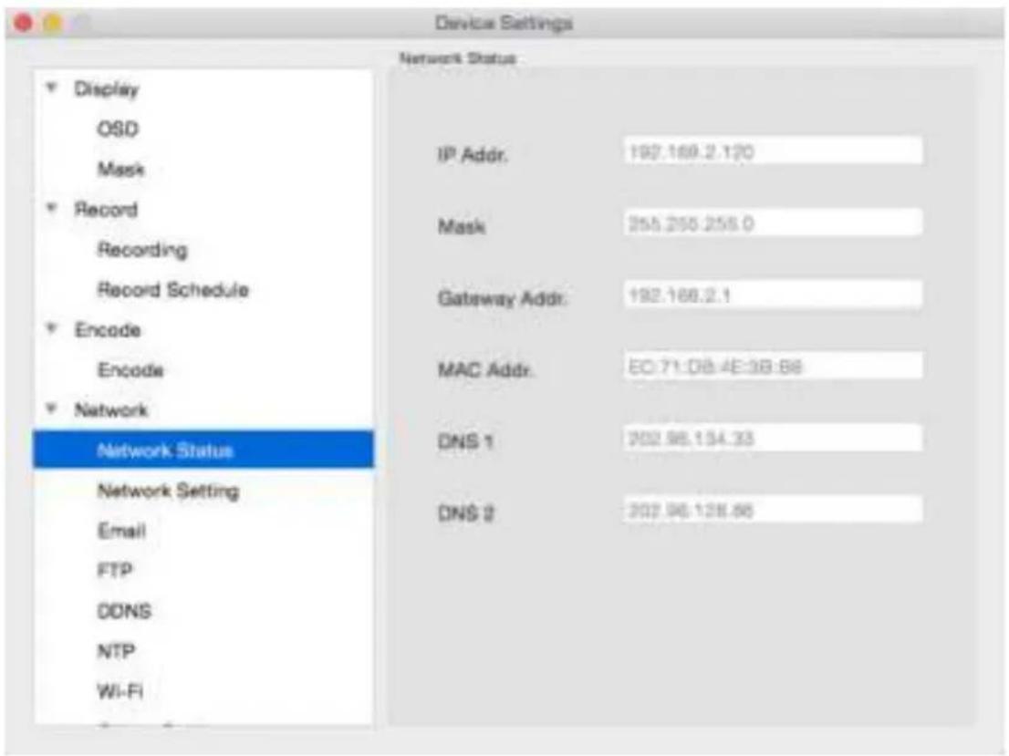
Here you may find the network information of the camera that you are viewing :
IP Address
- Subnet Mask
- Gateway
- Preferred DNS
Alternate DNS
For more details, you can refer to next page of Network -> Network Setting
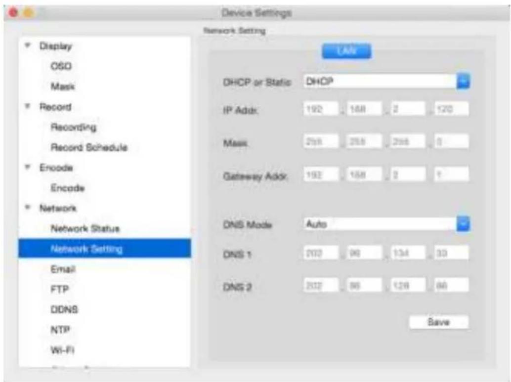
- DHCP or Static Access: Here you can choose between the two different types of networks that the Camera can be connected to. The two types of networks are:
- DHCP: DHCP is a system where one device on your network (usually a router) will automatically assign IP address to device connected to the network.
-
STATIC: Static networks require all devices to have their IP addresses manually defined, as there is no device dedicated to automatically assign IP address.
-
IP Address: Just as Home and Office needs to have an address which identifies their location on the road network, the Camera uses IPv4 addressing, which consists of four groups of numbers between 0 and 255, separated by periods. For example, a typical IP address might be "192.168.1.24" or similar.
- Subnet Mask: If the IP address is like a street address, then a subnetwork is like your neighbourhood. This will be formatted in a similar way to the IP address (ie. four numbers up to 255 separated by periods) but contain very different numbers. In the above example, the Subnet Mask might be something I "255.255.255.0".
• Gateway: This is the address of the “way to the Internet.” To continue the road analogy, this is like your local access point to the highway. This is an IP address in the same format as the others, and is typically very similar to the IP address of the Camera. To continue the above example, it might be something such as: “192.168.1.254”. - Auto DNS / Static DNS: Choose how you would like to define your DNS servers. We recommend leaving it on Auto configuration.
• Auto DNS: The Camera will automatically choose a DNS server. This is the recommended setting.
• Static DNS: If you need to manually define a DNS server, then choose Static DNS. This is recommended for advanced users only. - MAC Address: The Media Access Control address. This is a unique code which nothing else should share. You can't change this one - it's pre-set when the Camera ships out.
*Note: Many of the above networking settings are not required when using ReoLink P2P for remote access.
We suggest using Gmail as your email client - it's quite easy to set up an account and use it solely for the Camera. Other email servers may not work correctly. For the Auto-Mail function to work correctly, the Camera will need to be correctly configured with the details of the email servers and addresses you want to use.
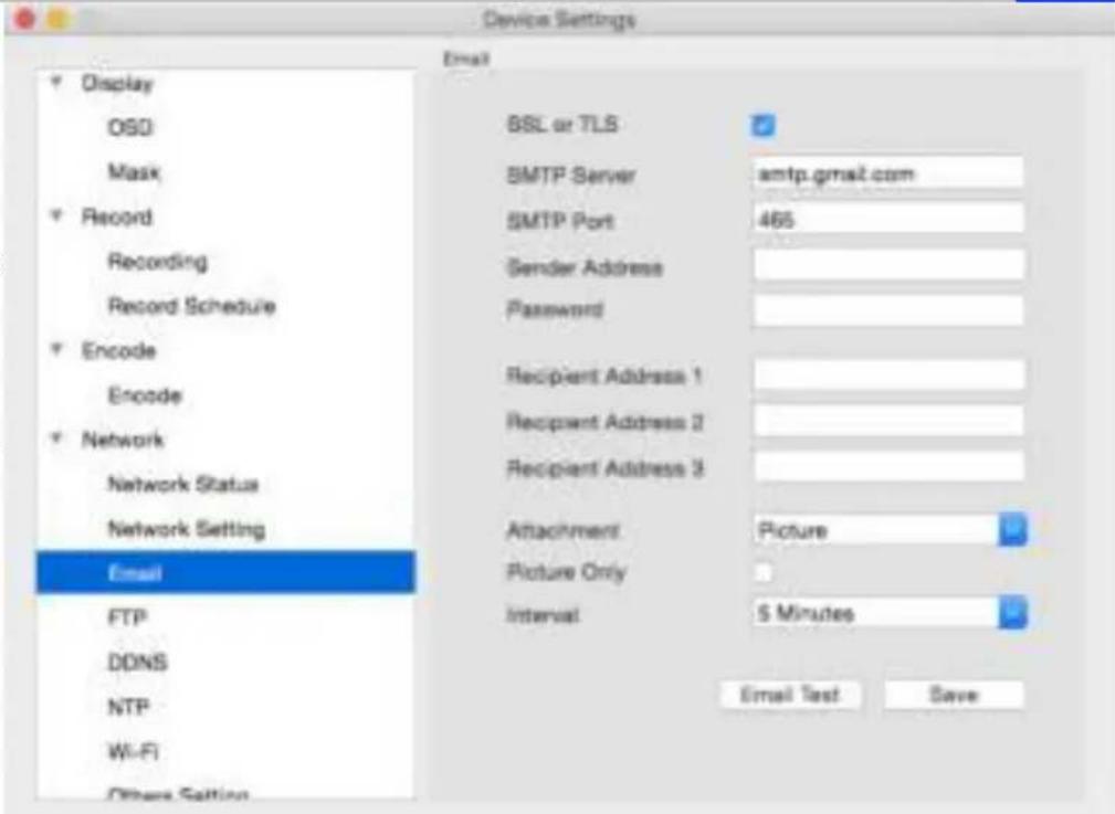
- Enable SSL or TSL:
Whether the email server you're using requires a secure link. This is on by default and should be left on if you're using any of the preset email servers.
- SMTP Server: You may use below mailbox : Gmail (smtp.gmail.com), Windows Live Mail (smtp.live.com) and Yahoo Mail (smtp.mail.yahoo.com).
You'll need to setup an account with one of these email providers. All offer free email accounts. The Camera will automatically adjust some settings to make the configuration significantly easier. If you want to use a different email server, typically the outgoing email server of their ISP, then you'll need to contact your ISP to learn the correct values.
- SMTP Port: The SMTP port used by the email provider of your choice. This field will automatically self-populate if you use one of the presets.
- Sender Address: The address you're sending the email from. This will be the username you've set up for the email server you're using, followed by "@" and then the email server. For example: "youraddress@gmail.com" or similar.
- Sender Password: The password for the outgoing email account.
- Recipient Address: The email address you want the Camera to send emails to. Note that the Camera might send a large number of automatic emails under certain conditions.
- Attachment: You can select to attach picture or video when send e-mail or receive only notification.
For motion-based email alerts, this will be an image of whatever triggered the motion detection.
- Interval: The length of time that must elapse after the Camera sends an email alert before it will send another.
Short Interval settings are likely to lead to huge numbers of alerts being sent by the Camera - perhaps even several emails for one event (if that one event lasts longer than the interval setting). On the other hand, a long interval setting might mean you'll miss a specific update that you needed. It will depend on your requirement.
Click E-mail Test button to test your setting is succeed or not, it setting succeed, you will receive a e-mail from the receiver mailbox to notify that your setting is succeed.
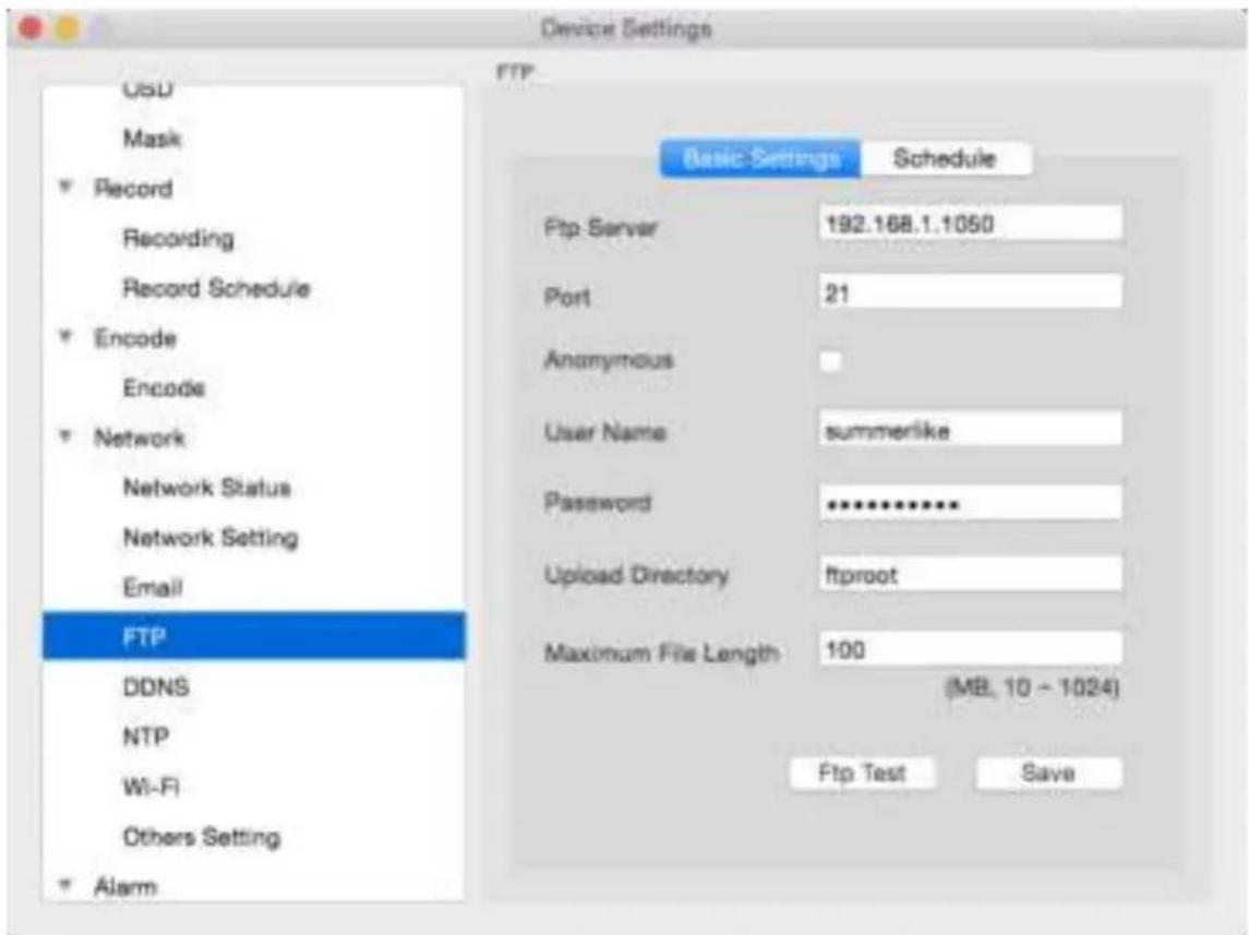
- FTP: File Transfer Protocol, you can use FTP to transfer files between Camera and computers on a network.
- FTP Server: Your FTP server address, can be IP address or the FTP link address, then input the FTP port # .
- Anonymous: If your FTP does not need username and password, you can click the Anonymous checkbox, else you need to input your FTP username and password below.
- Upload Directory: You need to input the upload folder name here.
• Maximum File Length: You may manage your FTP storage file size, the default setting is 100MB/file. - FTP Test: After finished setting, you may click Testing to verify your FTP settings, it will show FTP Test Succeed or FTP Test Failed on the bottom of the window. If setting is failed, please check your configuration again.
Click Save to save the settings.
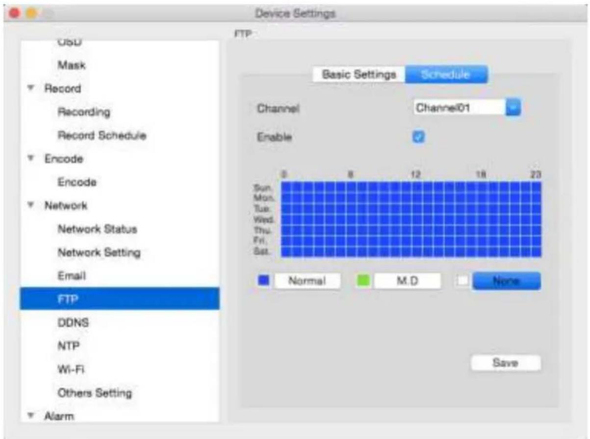
- FTP Schedule: You may set the FTP schedule time from below window, then click OK to save settings. Choose the Channel you want to setting FTP
Enable the Schedule setting
Blue Grid, Normal, means continuous recording to FTP
Green Grid, Motion Detection, means only when motion detection happen, it starts to recording to FTP White Grid, means no recording
You can setting the FTP schedule according to you personally requirement.
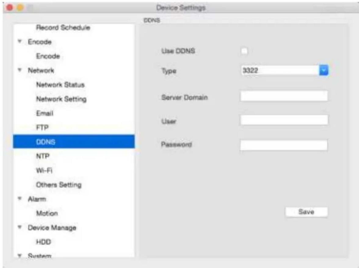
If you want to use DDNS, you need to enable DDNS function here.
- DDNS Type: Choose the server that you're using. here you can choose 3322 or DYDNS
- Server Domain Name: Enter the host name that you set up in your DDNS service. This is the address you use to access your network.
- Username and Password: Enter the username and password you setup with your DDNS server. These do not have to match your username/password combination in either your Camera or router. (for the sake of security, we suggest making them different).
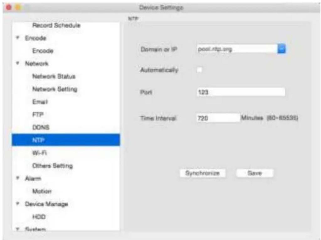
- NTP Server Domain or IP : The server you intend to use to access the current date and time. The default is pool.ntp.org.
• NTP Port: The port that the NTP server uses. The default for pool.ntp.org is 123. - Enable Automatically: click the checkbox to enable Auto-Sync
• Time Interval : to set the Sync interval time .
Important: If you have enabled NTP - set this to the time zone where you are. For example, people in Eastern Australia (Canberra, Sydney and Melbourne) choose GMT+10:00, whilst the Eastern Time zone in the USA and Canada is GMT-05:00. (GMT stands for Greenwich Mean Time - it's the baseline that keeps all the different time zones in sync.)
NOTE: Some NTP servers are NOT fully compatible with DST (Daylight Savings Time). This may cause your system to double-count adding one or removing one more hour than they should, or cancel each other out. You may need to change your time zone to adjust accordingly or simply not use NTP and DST simultaneously.
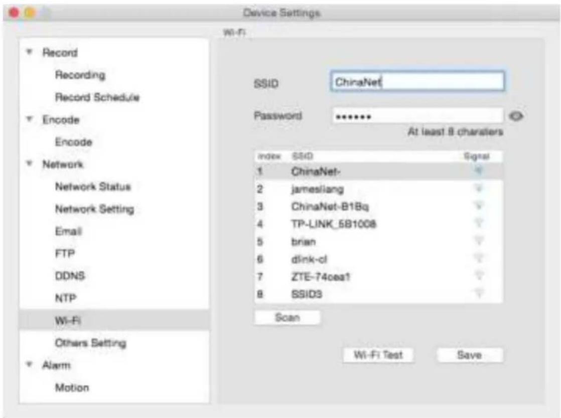
Here you can setting the WIFI of the Camera. This function is only valid for the WiFi Camera.
1, Click Scan Button, it will show all the WiFi Signal SSID and the WiFi Signal Strength.
2, Choose the WIFI you want to join in, Suggest choose the signal which show better WIFI performance.
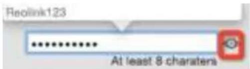
3,Then input the WIFI password. You can choose show password (the Eye look button)to check if the password you input is correct or not. Reolink123
4, After then , you can click WiFi Test Button , to test if the WIFI Setting is succeed . If succeed ,it will show WiFi Test Succeed on bottom , if not will show WiFi Test Failed .
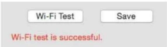
If WiFi Test Failed, you need to double check:
a) if the SSID password is correct
b) If the Antenna on WiFi Camera connected properly
c) if the WiFi Router working well
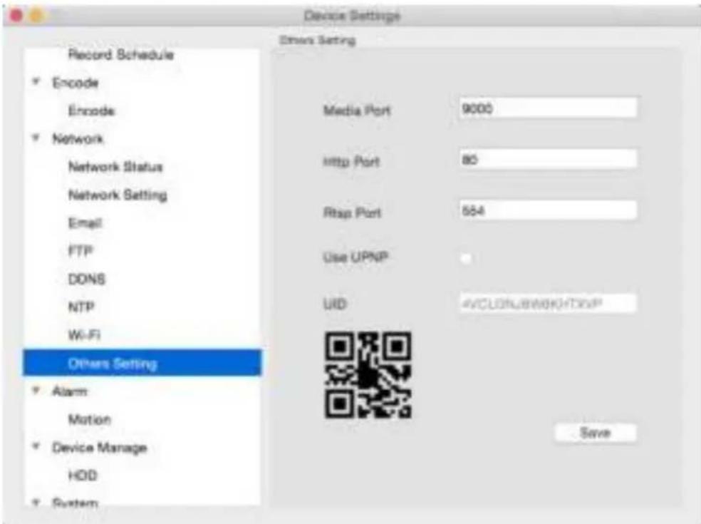
• Media Port: Camera will use server port to send information through. Please note that,
You'll need to enable UPnP on your router so your router can selectively open these ports, allowing the Camera to communicate via the Internet. If your router doesn't support UPnP, You may either get a new router (which support UPNP) or you can manually forward ports from the router to the Camera. Port Forwarding is a technical process and may require router knowledge.
The default port number is 9000, which is not used by many other devices/programs. However, if you have another Camera or Camera-like device, this port may be used already. If this is the case, change this value to be unique.
- HTTP Port: This is the port through which you will be able to log in to the Camera. it will need to be forwarded properly in order to ensure smooth, latency-free communication. The default value is "85", as this port is seldom used by other devices. If another device on your network is using this port, please change to other value. This is the port number you'll need to remember when logging in remotely from a remote PC via the HTTP interface.
What port number(s) should I use?
If the default port numbers are in use (85 and/or 9000) if 85 is already taken, try 86 or 87.
There's no "right" port number, any port number will work, avoid using port numbers 80, 81, 82, 88, 90, and 99 as these are often used by other devices.
- RTSP Port: Real Time Streaming Protocol", you may use this port to send the streaming file to Realplayer, the default RTSP port is 554
- UPNP enable (This feature is not required if you are using ReoLink P2P to access the Camera): UPnP makes configuring your network easier and faster. To use the UPnP setting on the Camera, you'll need a router which supports this feature, with UPnP enabled. Note that many routers which do support UPnP do not come with the feature enabled by default. You may need to ask your Internet service provider to turn it on.
When UPnP is enabled on your Camera and your router, the Ports that the Camera requires to be open for access to and from the Internet will automatically be opened and closed as necessary by your router, saving you the trouble of manually forwarding these ports. If UPnP is not enabled, or your router does not support this feature, you'll need to forward the ports the Camera uses from the router to the Camera - since this is a technically challenging process, we strongly recommend using UPnP if possible.
UID: The Camera's Unique IDentifier code for P2P. For convenience, you may have this code sent to your email account by clicking the Send UID button(provided that you've already set up your email account).
Alarm -> Motion
How Motion Detection Works?
The way that the Camera detects motion is quite straight forward - it's a process where it compares one frame with the next. A certain amount of "difference" between these two "frames" is interpreted as motion.
As a result, the Camera is able to detect when there is a change in the picture. However, this does not necessarily need to be something moving in the frame. For example, a light being turned on or off, a lightning flash or even the sun coming out momentarily on a cloudy day might be enough to trigger the motion detection on the Camera. However, as these events last only a moment (and are relatively rare) they will only create a few redundant clips, which will not take up too much space or pose a problem with scanning through footage.
For this reason, don't use PTZ systems and motion detection simultaneously. The Camera will interpret the camera moving as 'motion' and record. This is particularly true when using Cruise Mode - as the camera is moving almost continuously, so too is the Camera recording almost continuously!
Here, you'll be able to set the motion detection features of the Camera for each channel. We suggest that motion detection, under most circumstances, is the most practical recording method for the Camera to employ.
How it Works: Once motion detection has been enabled for a channel, it will register to the Camera as a Motion Event. Thus, you can use the Motion recording mode in the schedule to trigger the Camera to record when motion detection triggers an alarm signal.
- False Triggers
Setting the motion detection at high sensitivity levels (4 or lower) increases the frequency of false alarms. On the other hand, low sensitivity levels (20 or higher) increase the risk that a significant motion event (such as an intruder) will not trigger the motion detection to record.
Check the Motion Detection settings both during the day and night. In low-light conditions (or when your cameras are using infrared night vision) the Camera may be more or less sensitive to motion, depending on the circumstances. The difference might be very dramatic!
- Weather
The weather conditions are going to affect your motion detection. Dramatic weather phenomenon such as heavy rain, strong winds, lightning and so on, may trigger the motion detection with surprising frequency. On the other hand, things like fog, mist and other obscuring kinds of weather might mask or obscure something moving to the point that the Camera fails to detect them.
Here are a few steps you can take to minimise the amount of noise in your images.
- Try adjusting the Image Settings to fine-tune the brightness and contrast to get a more stable image.
- Limit the motion sensitive area to only the areas in view that a target could be. In particular, large featureless areas in the camera's view are the ones most likely to give false triggers - turning off the motion sensitivity to any area a target cannot move in front of will help reduce false triggers.
Note: The motion detection feature will seem more sensitive at night, particularly when using low-light or active infrared cameras. We recommend that you test your motion detection sensitivity both during the day and at night to ensure your sensitivity setting is suitable for either lighting condition.
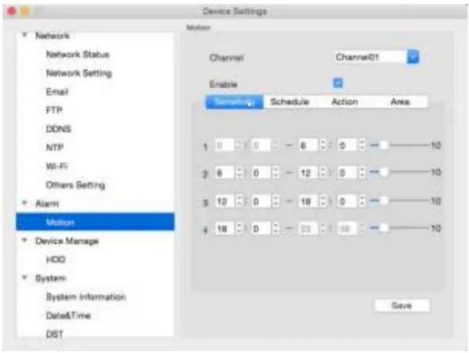
- Sensitivity: If the motion detection sensitivity is too high, then the Camera will record too frequently or continuously - any benefit of motion detection will be lost. If the motion detection sensitivity is too low, then the Camera will not record when it should and may not record anything at all. Here you may set the sensitivity on different time, for example, night time sensitivity is higher and day time sensitivity is lower for frequent movement on the daytime.
- Sensitivity Setting: The Sensitivity setting is controlled by a slider, allowing you to set a value between 0 and 10. The lower the number, the more sensitive the motion detection will be. 1 is the highest sensitivity.
There are four time periods which you may define different motion sensitivity values.
You may change each period's start and end time to best match the changing lighting conditions in your location.
Values between 5 - 10 will give good results in the daytime.
At night, you may get numerous false triggers unless you raise the sensitivity setting, perhaps as high as 1 - 5. This is because when cameras use active infrared night vision, they dramatically increase the gain controls to the image sensor. This creates a level of “noise” in the camera’s images, which are interpreted by the Camera as motion.
By default, the day is divided into four periods:
• 00:00 (Midnight) - 06:00 (6:00 AM)
• 06:00 (6:00 AM) - 12:00 (Mid-day)
• 12:00 (Mid-day) - 18:00 (6:00 PM)
• 18:00 (6:00 PM) - 00:00 (Midnight)
You might need to shift the beginning and end times to best suit the lighting condition at your location.
The start and end times can be set to anything you like, provided the different time periods don't overlap and there's no gap between one ending and the next starting.
There's no requirement for all four time periods to have different sensitivity levels, although we suggest that usually gives the best performance.
To find the best sensitivity values for different times of day/night, it's best to test the system during different time periods. Get an able-bodied volunteer to move about in front of the cameras you'd like to tune the sensitivity for. The ideal sensitivity level is when your volunteer moving about always triggers the motion detection, but there are no false triggers (or very few) when your volunteer isn't moving about.
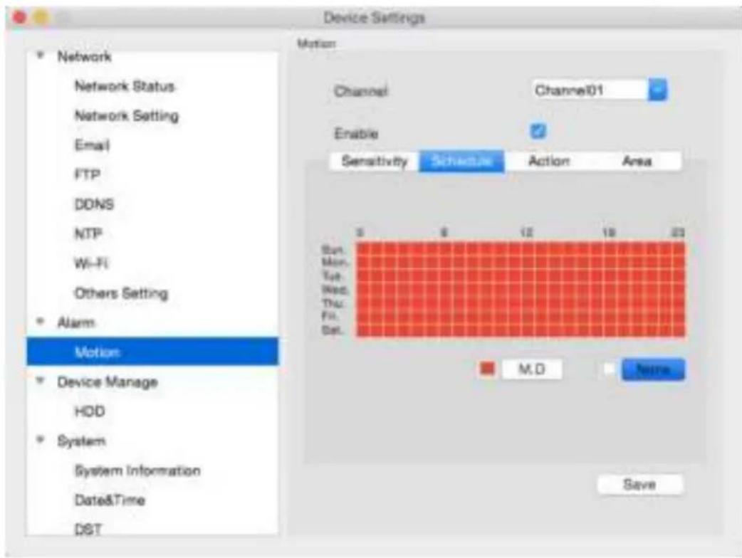
Here you may set the schedule time 7 days, 24 hours a week, red box means when motion is detected, it will trigger an alarm.
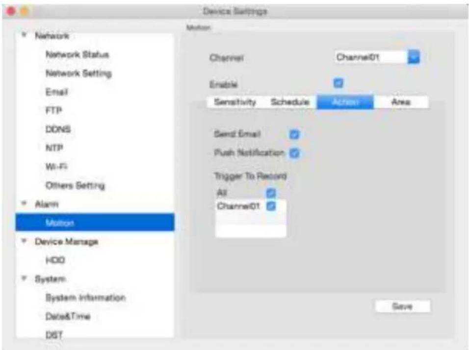
Here you may define what will happen when the camera you've selected detects motion. You may enable Audio Warning, and send e-mail when motion happens.
Enable: Whether or not motion detection is enabled on a specific channel. Each channel can be configured independently to one another.
Send Email: The Camera will send an auto-email alert when the event type you have selected occurs.
Push Notification: When motion happen, it will send a push notification message to you, This is only valid for some models, kindly please check with our support.
Trigger to Record: When motion happen, it will start record, you can setting trigger to record for all the channel or your selected channels.
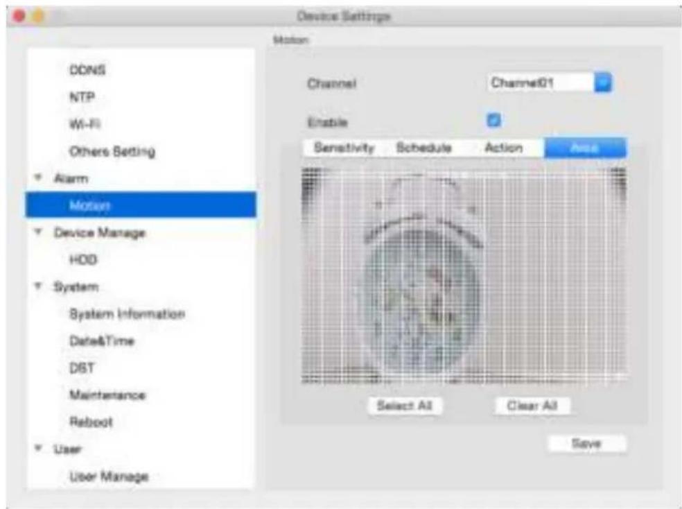
Click , you will see a grid of white boxes. The outlined boxes mark the area that is sensitive to motion. The area without the white outlines is not sensitive to motion. Click mouse to select and click again to de-select .
natural_image
Blurred image of a person in a lab coat, possibly a medical or laboratory setting, with no visible text or symbols.Use the mouse to move the cursor around the screen. By pressing select an area in the grid or you can drag to draw an area, you may toggle mot detection ON or OFF in that location.
Areas marked by white boxes will be sensitive to motion, those not marked will not be.
Click and drag to select the area you want to select or de-select.
- Select All means Full Screen: Setting the motion detection area, you may drag the box to un-choose the area. For example, you can using the grid to cover your front door, so your front door will be set as the motion detection area.
- Clear All: Clear Area means no area for motion detection.
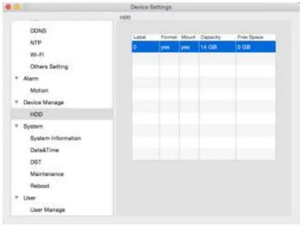
Here you can see the Micro SD card info, this function is only valid when you connect with built-in SD card devices.
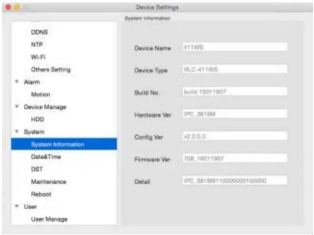
If you're looking at the System Information screen, you've probably been directed to do so by Technical Support. If we haven't told you to come here, you might be wondering what all the information means. On a day-to-day level, the answer is "very little". However, if you're still curious:
Device Name: The name that the Camera considers to be its own, and what it will use to register an IP address with your DHCP host.
The remaining information is for use by Technical Support, in the event that you require assistance. The various model and build numbers help us track down any known issues, or catalogue new issues as they come to light. It also helps us figure out if you're running the most recent firmware on the Camera, and whether you'd benefit from an upgrade.
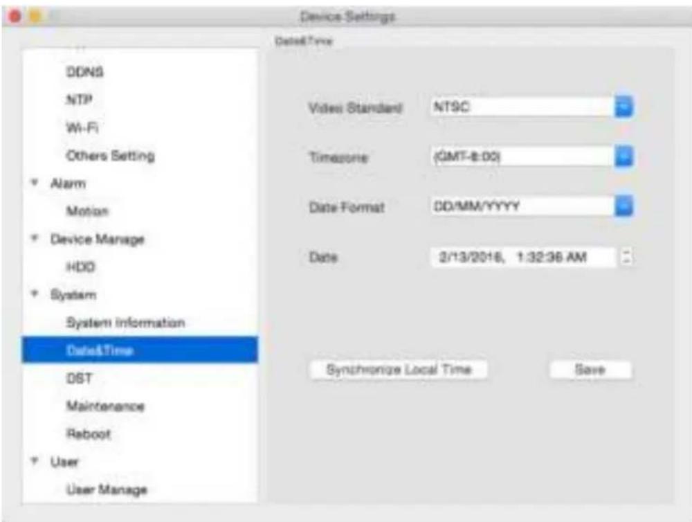
- Video Standard: Here you can choose between PAL and NTSC. PAL is used in Western Europe and Australia, NTSC is used in the US, Canada and Japan. If the Camera's picture is black and whit flickering or similar, then this is probably caused by the video system being set incorrectly.
• Time Zone: Particularly important if you have enabled NTP - set this to the time zone where you are. For example, people in eastern Australia (Canberra, Sydney and Melbourne) choose GMT+10:00, whilst the Eastern Time zone in the USA and Canada is GMT-05:00. (GMT stands for Greenwich Mean Time - it is the baseline that keeps all the different time zones in sync.) - Date Format: The format of the date (eg. DD/MM/YYYY or MM/DD/YYYY and so on).
- System Time: This can be edited manually, or set to update automatically by using NTP.
- Synchronize Local time : After clicked this button, Camera time will sync with local PC time .
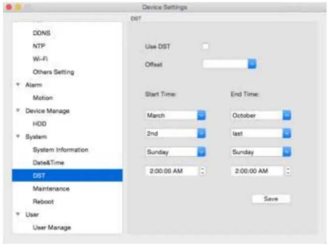
- DST Setting: As the standards for daylight savings differ from country to country, and often state to state, you might need to manually tell the Camera exactly when it commences and ends in your locality. First, turn DST on. We suggest setting the Daylight Saving Time Mode to Date, and manually entering the dates and times that daylight savings time applies to and from, in your locality.
Note: Some NTP servers are NOT fully compatible with DST. This may cause your system to double-count adding one or removing one more hour than they should, or cancel each other out. You may need to intentionally change your time zone to compensate, or simply not use NTP and DST simultaneously.
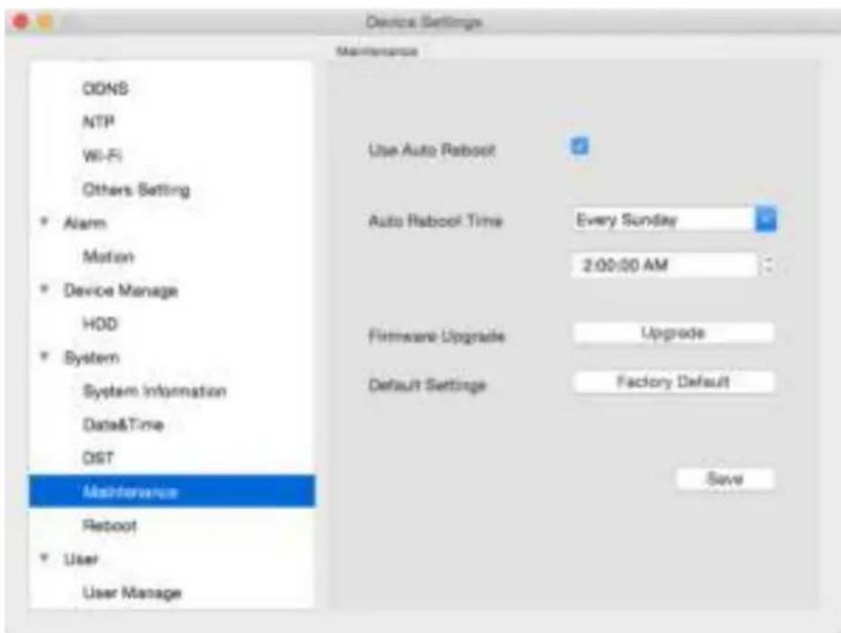
To maintain the operational integrity of the camera, it is suggested that it must be rebooted periodically. In much the same way that a computer can become unstable if left on for an extremely long time, the camera can become unstable too. It is strongly suggested that the camera be rebooted at least once per v However, as this can be a hassle (particularly if the camera is installed away) you can set the camera to reboot itself.
- Enable auto reboot: Will automatically shut down and restart a camera at a certain time of the day or week.
- Auto reboot Time at: Choose when you'd like the camera to reboot. Typically, this will be a time when it's unlikely there'll be any activity for the camera to record.
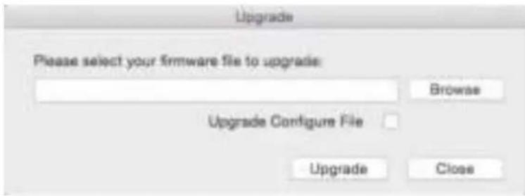
- Firmware Upgrade: Instructs the Camera to update its firmware. You'll only need to use this option if instructed to do so by Reolink Technical Support. Browse the file then click upgrade.
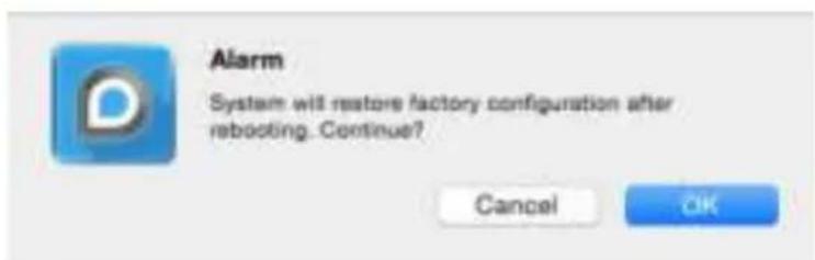
- Default Settings: Loads the Factory default settings. This must be done after a firmware upgrade to ensure proper operation of the Camera.
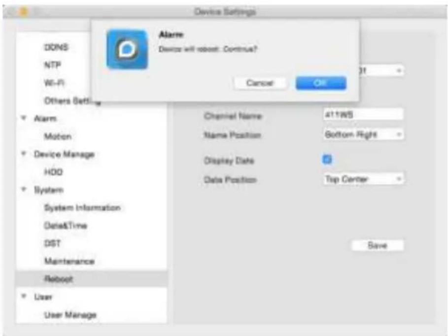
If you want to reboot the camera, click on the Reboot, it will show below windows, click OK to continue reboot.

Alarm
Device will reboot. Continue?
Cancel
OK
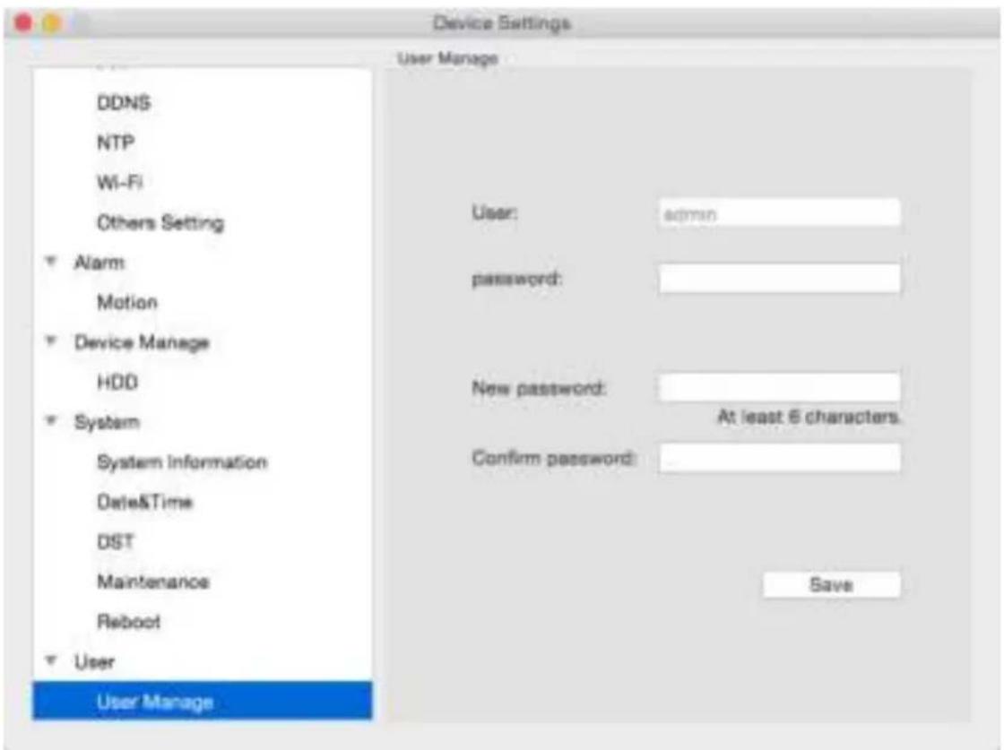
Here you may edit the user by modify password and click Save to save the new password.
Optical Zoom (For Zoom Camera Only)
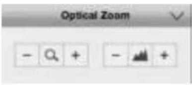
The Optical zoom setting can be only show when you connect to the camera have zoom functions, you can zoom and focus camera here. (This is for 411 422 Camera)
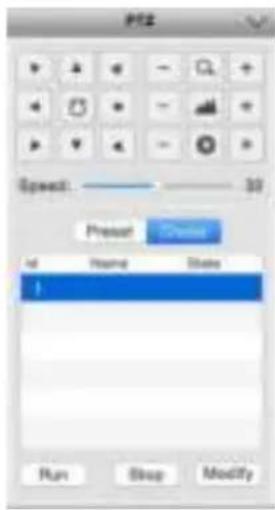
If you connect with PTZ Camera RLC-423, you will see the left side setting parameter.
You can set :
Zoom in / Zoom Out
Pan/Tilt position
Pan/Tilt Speed
Preset
Cruise
Set Preset
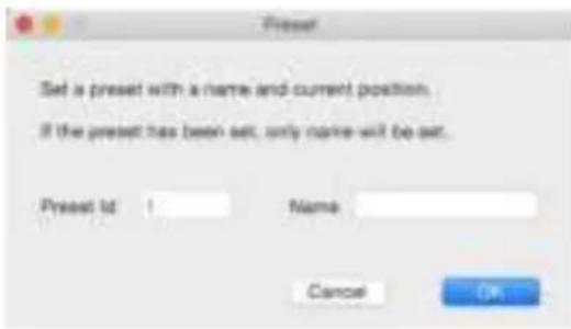
Click Preset , choose the ID , then click Modify, you can set the Preset ID name . Here you can set max to 128 Preset .
Set Cruise
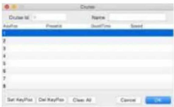
Click Cruise, choose the cruise ID then click Modify, you can choose the Key position which you want to modify, Click Set KeyPos or Del KeyPos to do your setting.
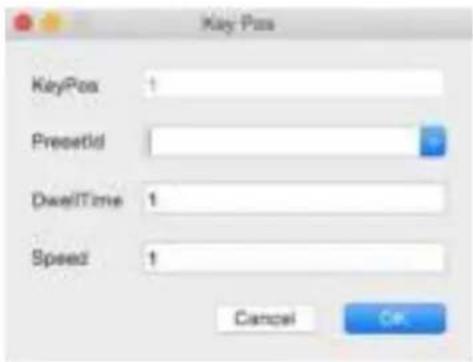
When you click Set KeyPos , you will see the Key Pos page , you can choose the preset ID fromthe pulldown list .
Dwel Time is the time of seconds you want to stay at that KeyPos , here 1 means 1 second. Speed you can set from 1 - 32 , 1 is the lowest and 32 is the fastest .
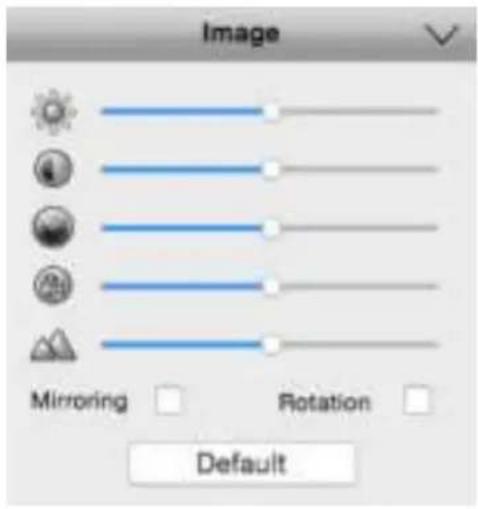
Brightness: Changes how light the image appears to be.
Contrast: Increases the difference between the blackest black and the whitest white in the image.
Saturation: Alters how much colour is displayed in the image. The higher the saturation, the more bright and vivid colours will appear to be.
Hue: Changes the colour mix of the image (this can have very dramatic results).
Sharpen: Sharpen image to increase the Signal Noise Ratio.
Mirroring: Change the orientation of the image to be horizontally reversed.
Rotation: Turn the image up side down.
Notice : Your image settings will affect your recordings!
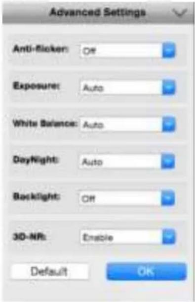
Advanced Settings: Adjust various camera settings according to the environment where the camera is installed.
• Anti-flicker: Use this feature if some devices such as TV screens and lights are flickering. For USA and Canada, set this to 60Hz. For Australia and the UK, set this to 50Hz. Outdoor mode is also available.
- Exposure Mode: Select the exposure level of the camera based on pre-defined conditions. Select Manual to adjust shutter speed and gain value of the camera manually.
- Contextual: Change the way the camera processes white balance to correct image colours. Auto, Day, Night or Manual (adjust the red and blue gain manually).
Day/Night: Set the camera's colour mode during different times of the day and night - AGC(Auto set by image sensor, Colour (Always in Day mode), Black&White (Always in Night mode) or CDS (Auto set by light sensor).
- Backlight: Optimise brightness and contrast levels to compensate for differences between dark and bright objects using either BLC or WDR mode. This may improve image clarity in high contrast situations but should be tested at different times of the day and night to ensure there is no negative effect.
• 3D-NR: 3D-Noise Ratio: if Enabled may decrease the noise of the image.
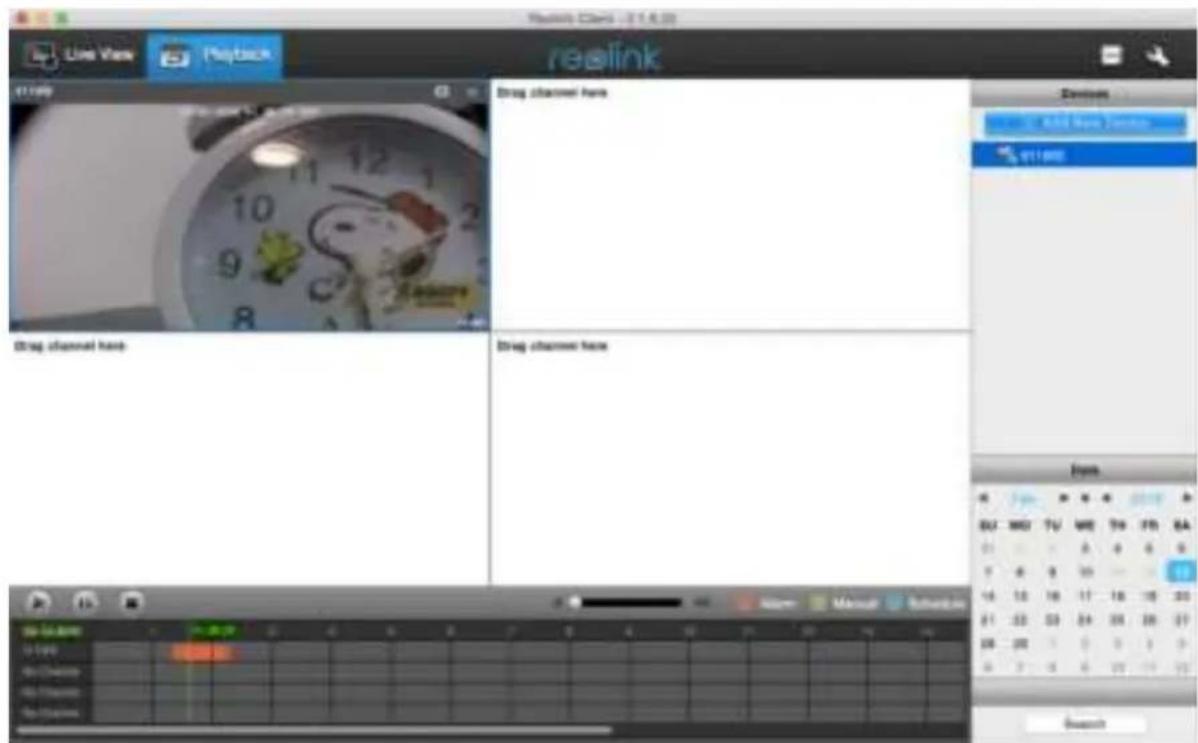
You can remotely playback the recording on the SD card .
- Click the device which you want to search the playback
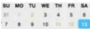
2.Choose the date from the date area , then click Search . Normally , if withrecorded file , the date color will be green , so that easy for you to identify .
-
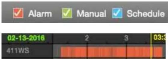
You can choose to search the Alarm / Manual/ Schedule recording here
-
After click Search , you will show the recorded file fromthe timeline slide , drag green line to the time which youwant to play back , then click Play button to play the file
Reolink warrants this product against defects in workmanship and material for a period of One (1) year from its original purchase date. You must present your receipt as proof of purchase for warranty validation. Any unit which proves defective during the stated period will be repaired without charge for parts or labour or replaced at the sole discretion of Reolink. The end user is responsible for all freight charges incurred to send the product to Reolink's repair centre. The end user is responsible for all shipping costs incurred when shipping from and to any country other than the country of origin.
The warranty does not cover any incidental, accidental or consequential damages arising from the use of or the inability to use this product. Any costs associated with the fitting or removal of this product by a tradesman or other person or any other costs associated with its use are the responsibility of the end user. This warranty applies to the original purchaser of the product only and is not transferable to any third party. Unauthorised end user or third pa modifications to any component or evidence of misuse or abuse of the device will render warranties void.
By law some countries do not allow limitations on certain exclusions in this warrant. Where applicable by local laws, regulations and legal rights will take precedence.
- User Manual V1.0 (MAC)
- CAUTION
- GETTING STARTED
- FCC Verification
- Important Note :
- FCC Regulation (for USA):
- Prohibition against eavesdropping
- WARNING
- IMPORTANT SAFETY INSTRUCTIONS
- RoHS:
- BATTERY INFORMATION
- BATTERY SAFETY INSTRUCTIONS
- CONTENTS
- Client Software
- Display
- Record
- Encode
- Network
- Alarm
- Device
- System
- User
- This page shows how Camera connect to the Network System
- Reolink Mac Client Software
- How to install Reolink MAC Software:
- Log on to Reolink
- IP Address
- UID
- Using the Live View Screen
- Alarm -> Motion
- How Motion Detection Works?
- - False Triggers
- - Weather
- Optical Zoom (For Zoom Camera Only)
- Set Preset
- Set Cruise
Brand : REOLINK
Model : RLK16-410B8
Category : Security Camera