
VR21 - Exercise bike NordicTrack - Free user manual and instructions
Find the device manual for free VR21 NordicTrack in PDF.


| Product Type | Recumbent Exercise Bike |
| Model | VR21 (NTEX76016C.0) |
| Dimensions (L x W) | 4 ft. 11 in. x 1 ft. 10 in. (150 cm x 56 cm) |
| User Weight Capacity | 350 lbs (159 kg) |
| Resistance Type | Magnetic with eddy mechanism |
| Console Display | Multi-function LCD with scan, priority, and demo modes |
| Connectivity | Bluetooth Smart for iFit app and heart rate monitors |
| Heart Rate Monitoring | Handgrip sensors and optional Bluetooth Smart chest strap |
| Fan | Multi-speed with auto mode that adjusts to exercise intensity |
| Sound System | 3.5 mm audio input for personal music players |
| Power Source | External power adapter (included), plugs into standard outlet |
| Workout Programs | Manual mode and multiple onboard workouts with automatic resistance changes |
| Seat Adjustment | Sliding seat with adjustment handle (forward/backward) |
| Pedal Straps | Adjustable with release tab |
| Transport Wheels | Built-in front wheels for easy movement |
| Leveling Feet | Adjustable rear feet for stability on uneven floors |
| Assembly Required | Yes, with two persons recommended; includes some tools |
| Warranty | Limited; register at iconservice.ca to activate |
| Maintenance | Regularly inspect and tighten parts; clean with damp cloth and mild soap |
Frequently Asked Questions - VR21 NordicTrack
User questions about VR21 NordicTrack
0 question about this device. Answer the ones you know or ask your own.
Ask a new question about this device
Download the instructions for your Exercise bike in PDF format for free! Find your manual VR21 - NordicTrack and take your electronic device back in hand. On this page are published all the documents necessary for the use of your device. VR21 by NordicTrack.
USER MANUAL VR21 NordicTrack
NordicTrack® C VR 21
nordictrack.ca
Model No. NTEX76016C.0
Serial No.
Write the serial number in the space above for reference.
ACTIVATE YOUR WARRANTY
To register your product and activate your warranty today, go to iconservice.ca.
CUSTOMER SERVICE
Call toll-free 1-888-936-4266
Mon.-Fri. 7:30 a.m.-4:30 p.m. ET
(excluding holidays)
or email us at
customerservice@iconcanada.ca
Please do not contact the store.
CAUTION
Read all precautions and instructions in this manual before using this equipment. Keep this manual for future reference.
USER'S MANUAL
natural_image
Line drawing of a stationary exercise machine with adjustable arms and legs (no text or symbols)iFIT
MAKE YOUR
FITNESS GOALS A
REALITY
IFIT.COM
TABLE OF CONTENTS
WARNING DECAL PLACEMENT 2
IMPORTANT PRECAUTIONS....3
BEFORE YOU BEGIN....5
PART IDENTIFICATION CHART....6
ASSEMBLY 7
HOW TO USE THE EXERCISE BIKE....14
MAINTENANCE AND TROUBLESHOOTING 21
EXERCISE GUIDELINES 23
PART LIST....24
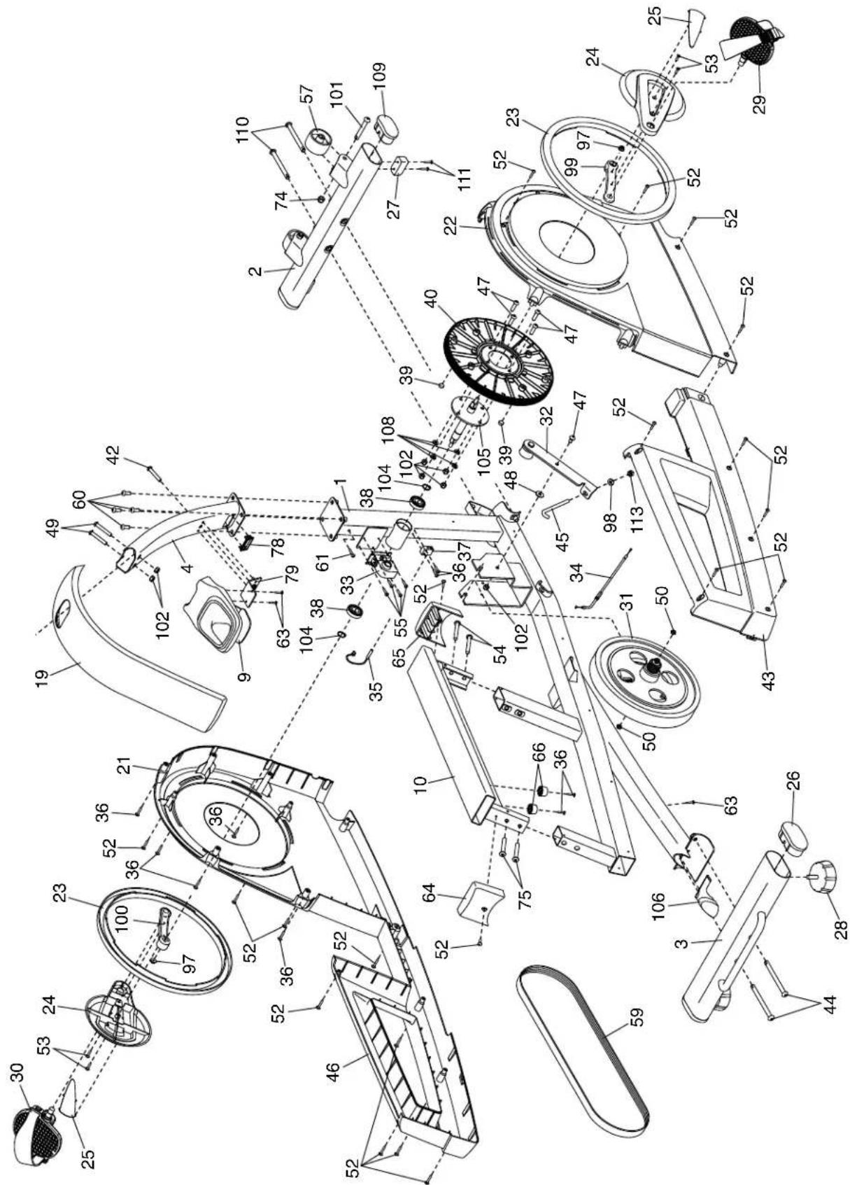
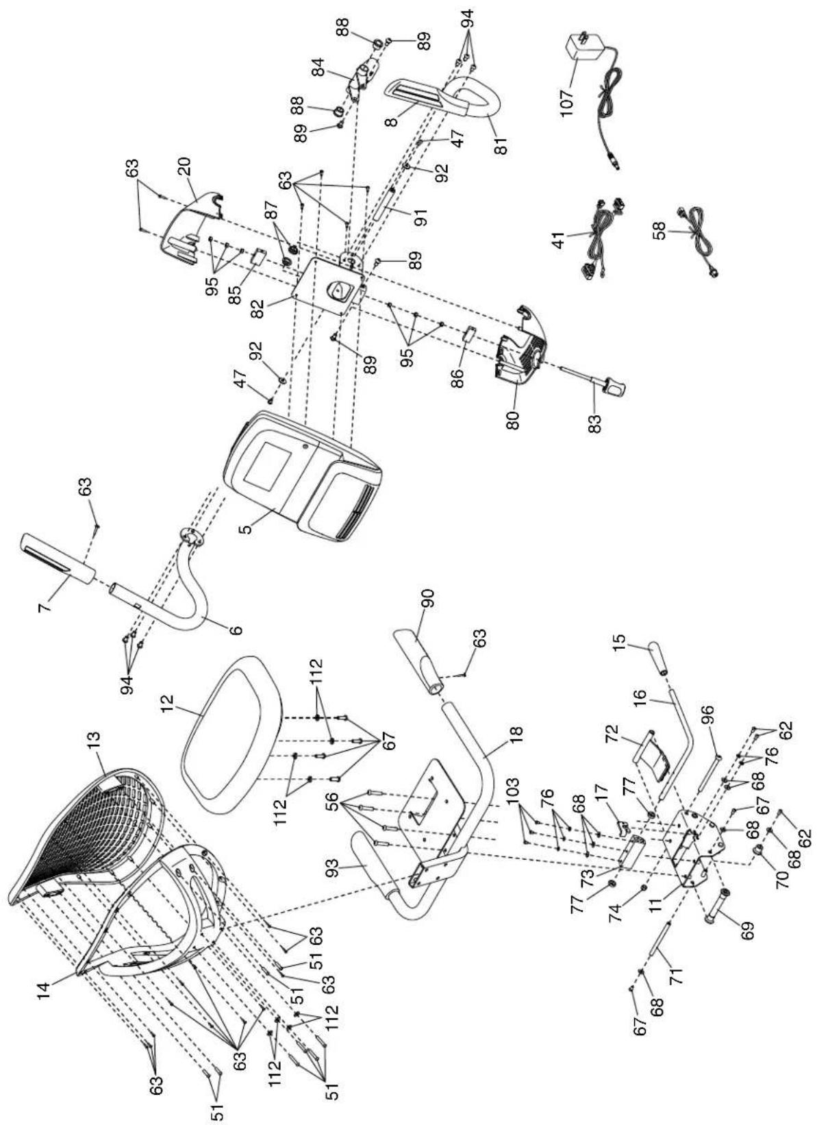
EXPLODED DRAWING....26
ORDERING REPLACEMENT PARTS Back Cover
LIMITED WARRANTY.... Back Cover
WARNING DECAL PLACEMENT
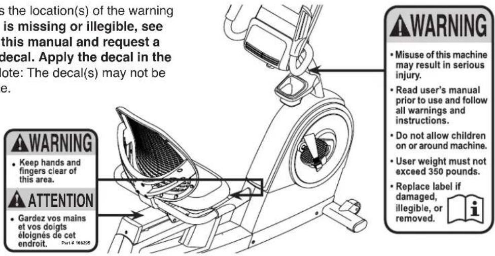
This drawing shows the location(s) of the warning decal(s). If a decal is missing or illegible, see the front cover of this manual and request a free replacement decal. Apply the decal in the location shown. Note: The decal(s) may not be shown at actual size.
NORDICTRACK and IFIT are registered trademarks of ICON Health & Fitness, Inc. App Store is a trademark of Apple Inc., registered in the U.S. and other countries. Android and Google Play are trademarks of Google LLC. The BLUETOOTH® word mark and logos are registered trademarks of Bluetooth SIG, Inc. and are used under license. IOS is a trademark or registered trademark of Cisco in the U.S. and other countries and is used under license.
IMPORTANT PRECAUTIONS
WARNING: To reduce the risk of serious injury, read all important precautions and instructions in this manual and all warnings on your exercise bike before using your exercise bike. ICON assumes no responsibility for personal injury or property damage sustained by or through the use of this product.
- It is the responsibility of the owner to ensure that all users of the exercise bike are adequately informed of all precautions.
- Before beginning any exercise program, consult your physician. This is especially important for persons over age 35 or persons with pre-existing health problems.
- The exercise bike is not intended for use by persons with reduced physical, sensory, or mental capabilities or lack of experience and knowledge, unless they are given supervision or instruction about use of the exercise bike by someone responsible for their safety.
- Use the exercise bike only as described in this manual.
- The exercise bike is intended for home use only. Do not use the exercise bike in a commercial, rental, or institutional setting.
- Keep the exercise bike indoors, away from moisture and dust. Do not put the exercise bike in a garage or covered patio, or near water.
- Place the exercise bike on a level surface, with a mat beneath it to protect the floor or carpet. Make sure that there is at least 2 ft. (0.6 m) of clearance around the exercise bike.
-
Keep children under age 13 and pets away from the exercise bike at all times.
-
The exercise bike should not be used by persons weighing more than 350 lbs. (159 kg).
-
Wear appropriate clothes while exercising; do not wear loose clothes that could become caught on the exercise bike. Always wear athletic shoes for foot protection.
-
Inspect and properly tighten all parts each time the exercise bike is used. Replace any worn parts immediately.
-
Be careful when mounting and dismounting the exercise bike.
-
Always keep your back straight while using the exercise bike; do not arch your back.
-
The heart rate monitor is not a medical device. Various factors may affect the accuracy of heart rate readings. The heart rate monitor is intended only as an exercise aid in determining heart rate trends in general.
-
Over exercising may result in serious injury or death. If you feel faint, if you become short of breath, or if you experience pain while exercising, stop immediately and cool down.
-
This Class B digital apparatus complies with Canadian ICES-003. The console contains IC:3673A-BMD1.
PROTECT
YOUR FITNESS EQUIPMENT
WITH AN EXTENDED SERVICE PLAN
Your new fitness equipment represents a significant investment in your health. Protect your investment now from unexpected mechanical or electrical failures for up to five years.

natural_image
Abstract gear and shield icon with interlocking gears (no text or symbols)PLAN FEATURES
• Protection for one to five years
• Over 100 authorized repair centers
• Highly trained repair technicians
• A national toll-free repair hotline
• Simple repair claim procedure
- No claim forms
- Easy enrollment
• Fast, efficient repair anywhere in Canada
• In-home repairs covered - Parts and labour covered
• Mechanical and electrical failures covered
To protect your fitness equipment today, please
call Customer Care at 1-888-936-4266
Or, email us at customerservice@iconcanada.ca

BEFORE YOU BEGIN
Thank you for selecting the new NORDICTRACK® C VR 21 exercise bike. Cycling is an effective exercise for increasing cardiovascular fitness, building endurance, and toning the body. The C VR 21 exercise bike provides a selection of features designed to make your workouts at home more effective and enjoyable.
For your benefit, read this manual carefully before you use the exercise bike. If you have questions after
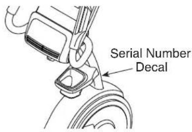
reading this manual, please see the front cover of this manual. To help us assist you, note the product model number and serial number before contacting us. The model number and the location of the serial number decal are shown on the front cover of this manual.
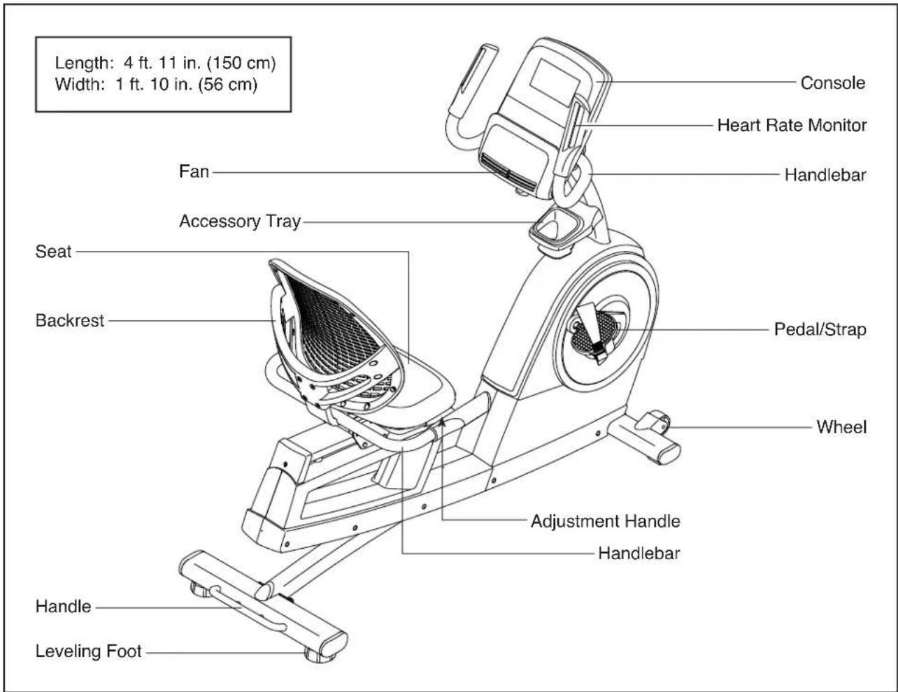
Before reading further, please familiarize yourself with the parts that are labeled in the drawing below.
PART IDENTIFICATION CHART
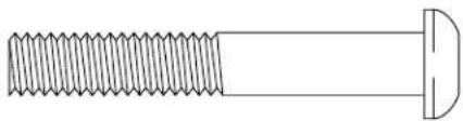
Use the drawings below to identify the small parts needed for assembly. The number in parentheses below each drawing is the key number of the part, from the PART LIST near the end of this manual. The number following the key number is the quantity needed for assembly. Note: If a part is not in the hardware kit, check to see if it has been preassembled. Extra parts may be included.
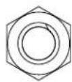
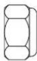
M8 Locknut (102)-2
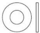
M6 Washer (112)-8
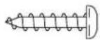
M4 x 15mm
Screw (63)-6
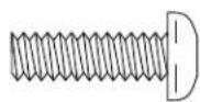
M6 x 20mm
Screw (67)-4
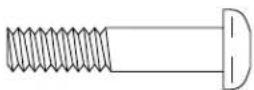
M6 x 30mm
Screw (51)-4
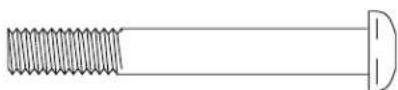
M6 x 50mm Screw (42)-1
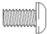
M8 x 13mm
Screw (94)-6
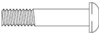
M8 x 40mm
Screw (56)-4
natural_image
Technical line drawing of a threaded bolt with a flanged end (no text or symbols)M8 x 50mm Bolt (49)-2
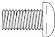
M10 x 20mm
Screw (60)-4

natural_image
Simple line drawing of a screw with a pin, no text or symbols presentM10 x 96mm Screw (110)-2

natural_image
Simple line drawing of a screw and pin (no text or symbols)M10 x 120mm Screw (44)-2
ASSEMBLY
• Assembly requires two persons.
- Place all parts in a cleared area and remove the packing materials. Do not dispose of the packing materials until you finish all assembly steps.
- Left parts are marked "L" or "Left" and right parts are marked "R" or "Right."
• To identify small parts, see page 6.
In addition to the included tool(s), assembly requires the following tools:
one Phillips screwdriver
one adjustable wrench
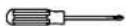
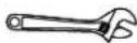
Assembly may be easier if you have a set of wrenches. To avoid damaging parts, do not use power tools.
1. Gotoiconservice.ca/CustomerService/registration and register your product.
• documents your ownership
• activates your warranty
• ensures priority customer support if assistance is ever needed
Note: If you do not have internet access, call Customer Service (see the front cover of this manual) and register your product.
1
natural_image
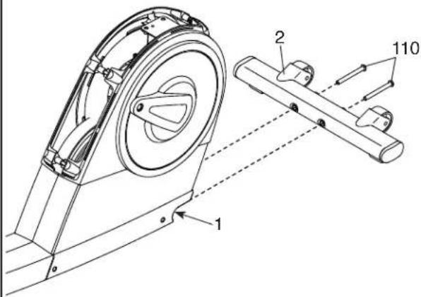
Line drawing of a laptop computer with blank screen and keyboard (no text or symbols)- If there are shipping bracket(s) on the front and rear of the Frame (1), remove and discard the shipping bracket(s) and the hardware attaching them.
With the help of a second person, place some of the packing materials (not shown) under the front of the Frame (1).
Attach the Front Stabilizer (2) to the Frame (1) with two M10 x 96mm Screws (110); start both Screws, and then tighten them.
Then, remove the packing material from under the Frame (1).
2
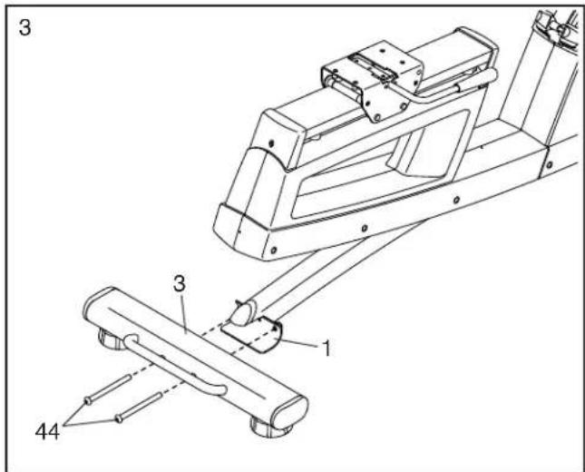
- With the help of a second person, place some of the packing materials (not shown) under the rear of the Frame (1).
Attach the Rear Stabilizer (3) to the Frame (1) with two M10 x 120mm Screws (44); start both Screws, and then tighten them.
Then, remove the packing material from under the Frame (1).
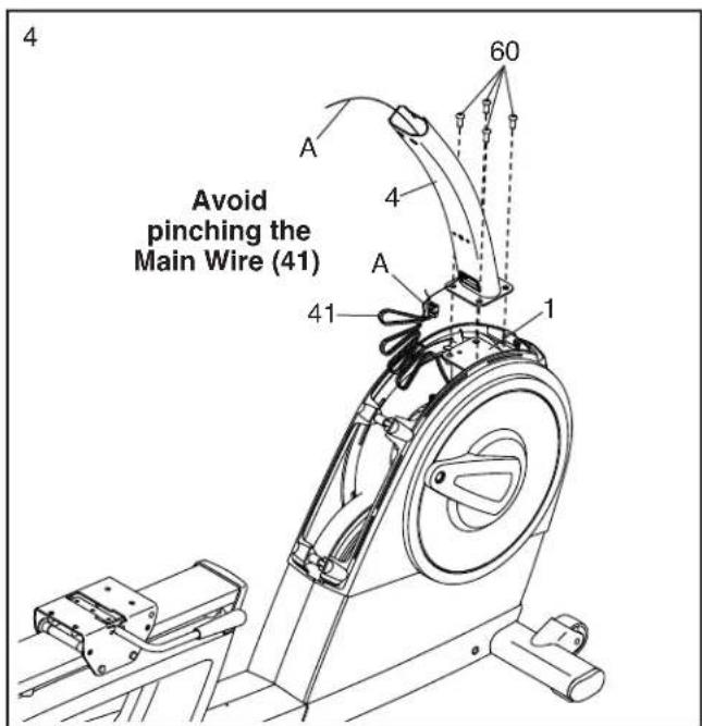
- Have a second person hold the Upright (4) on the Frame (1).
Tip: Avoid pinching the Main Wire (41). Attach the Upright (4) with four M10 x 20mm Screws (60); start all the Screws, and then tighten them.
Next, locate the wire tie (A) inside the Upright (4). Tie the lower end of the wire tie to the Main Wire (41). Then, pull the other end of the wire tie upward until the Main Wire is routed through the Upright.
Tip: To prevent the Main Wire (41) from falling into the Upright (4), secure it to the Upright with the wire tie (A).
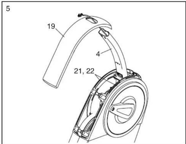
- Slide the Upright Cover (19) onto the Upright (4) and press it onto the Left and Right Shields (21, 22).
-
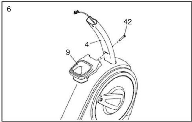
Attach the Accessory Tray (9) to the Upright (4) with an M6 x 50mm Screw (42).
-
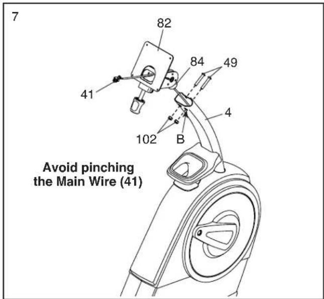
Untie and discard the wire tie on the Main Wire (41).
While a second person holds the Console Bracket (82) near the Upright (4), route the Main Wire (41) through the notch in the Upright, through the Upright Bracket (84), and through the hole in the center of the Console Bracket.
Tip: Avoid pinching the Main Wire (41). Insert the Upright Bracket (84) into the Upright (4).
Attach the Upright Bracket (84) with two M8 x 50mm Bolts (49) and two M8 Locknuts (102); start both Bolts, and then tighten them. Make sure that the Locknuts are in the hexagonal holes (B).
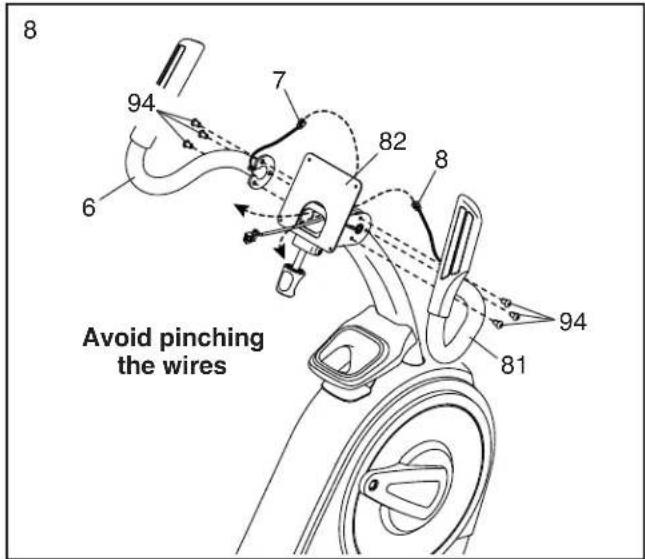
- Identify the Right Handlebar (81) and orient it as shown.
Tip: Avoid pinching the Right Pulse Wire (8). Attach the Right Handlebar (81) to the right side of the Console Bracket (82) with three M8 x 13mm Screws (94); start all the Screws, and then tighten them.
Then, route the Right Pulse Wire (8) in the Right Handlebar (81) through the Console Bracket (82) as shown.
Repeat this step to attach the Left Handlebar (6).
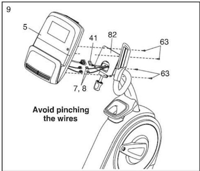
- While a second person holds the Console (5) near the Console Bracket (82), connect the wires on the Console to the Main Wire (41) and to the Left and Right Pulse Wires (7, 8).
Insert the excess wire into the Console Bracket (82).
Tip: Avoid pinching the wires. Attach the Console (5) to the Console Bracket (82) with four M4 x 15mm Screws (63); start all the Screws, and then tighten them.
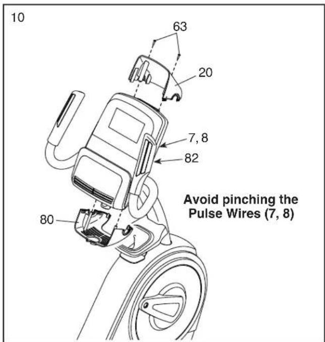
- Identify the Upper and Lower Bracket Covers (20, 80), orient them as shown, and press them together around the Console Bracket (82).
Tip: Avoid pinching the Left and Right Pulse Wires (7, 8). Attach the Upper and Lower Bracket Covers (20, 80) to the Console Bracket (82) with two M4 x 15mm Screws (63).
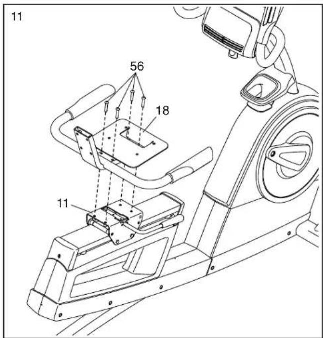
- Attach the Seat Handlebar (18) to the Seat Carriage (11) with four M8 x 40mm Screws (56); start all the Screws, and then tighten them.
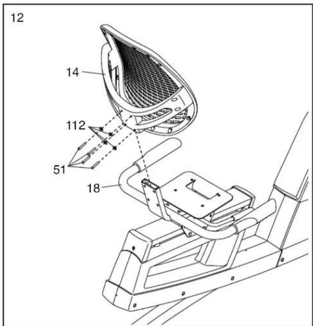
- Slide the Backrest Frame (14) onto the Seat Handlebar (18).
Attach the Backrest Frame (14) with four M6 x 30mm Screws (51) and four M6 Washers (112); start all the Screws, and then tighten them.
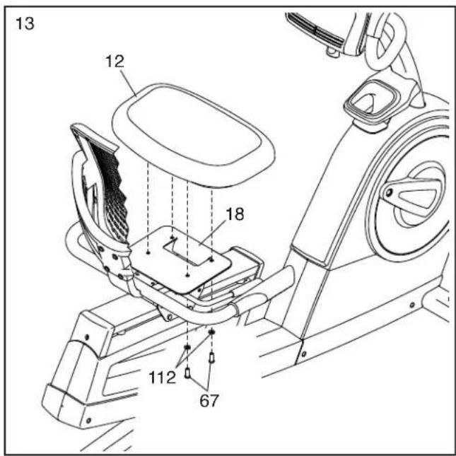
- Attach the Seat (12) to the Seat Handlebar (18) with four M6 x 20mm Screws (67) and four M6 Washers (112) (only two of each are shown); start all the Screws, and then tighten them.
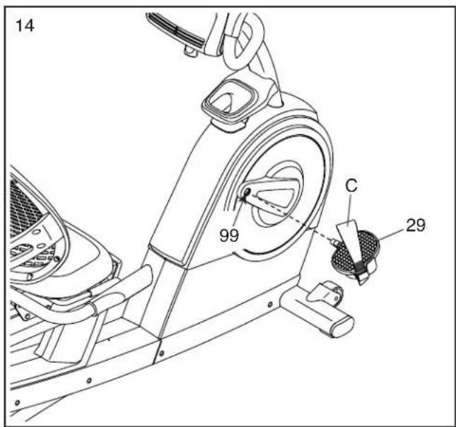
- Identify the Right Pedal (29).
Using an adjustable wrench, firmly tighten the Right Pedal (29) clockwise into the Right Crank Arm (99).
Firmly tighten the Left Pedal (not shown) counterclockwise into the Left Crank Arm (not shown). IMPORTANT: You must turn the Left Pedal counterclockwise to attach it.
Attach the right pedal strap (C) to the Right Pedal (29) as shown. Attach the left pedal strap (not shown) in the same way.
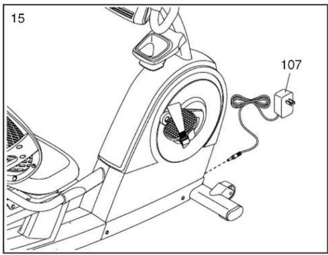
- Plug the Power Adapter (107) into the receptacle on the frame of the exercise bike.
Note: To plug the Power Adapter (107) into an outlet, see HOW TO PLUG IN THE POWER ADAPTER on page 14.
- After the exercise bike is assembled, inspect it to make sure that it is assembled correctly, that it functions properly, and that all parts are properly tightened. Extra parts may be included. Place a mat under the exercise bike to protect the floor or carpet.
HOW TO USE THE EXERCISE BIKE
HOW TO PLUG IN THE POWER ADAPTER
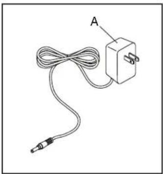
IMPORTANT: If the exercise bike has been exposed to cold temperatures, allow it to warm to room temperature before you plug in the power adapter (A). If you do not do this, you may damage the console displays or other electronic components.
Plug the power adapter (A) into the receptacle on the front of the exercise bike. Then, plug the power adapter into an appropriate outlet that is properly installed in accordance with all local codes and ordinances.
natural_image
Simple line drawing of a cable and plug connected to an electrical outlet (no text or symbols)HOW TO MOVE THE EXERCISE BIKE
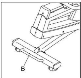
To move the exercise bike, hold the handle (B) on the rear stabilizer and carefully lift it until the exercise bike can be moved on the front wheels. Carefully move the exercise bike to the desired location and then lower it.
natural_image
Technical line drawing of a mechanical device with labeled component B (no text or symbols beyond label)HOW TO ADJUST THE ANGLE OF THE CONSOLE
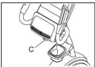
To adjust the angle of the console, turn the console knob (C) until the console is at the desired angle.
natural_image
Technical line drawing of a mechanical device with labeled component C (no text or symbols beyond label)HOW TO ADJUST THE SEAT
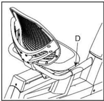
The seat can be adjusted forward or backward to the position that is the most comfortable. To adjust the seat, push downward on the adjustment handle (D), slide the seat to the desired position, and then pull upward on the adjustment handle to lock the seat
natural_image
Technical line drawing of a mechanical component with labeled part D (no text or symbols beyond label)HOW TO ADJUST THE PEDAL STRAPS
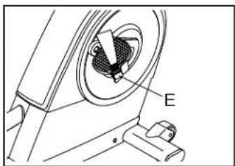
To tighten a pedal strap, pull downward on the end of the strap. To loosen a strap, press the tab (E) and pull upward on the strap.
natural_image
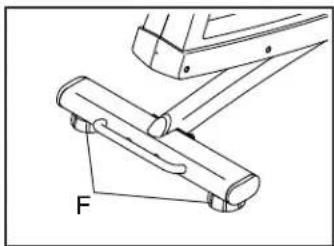
Technical line drawing of a mechanical device with labeled component E (no text or symbols beyond label)If the exercise bike rocks slightly on your floor during use, turn one or both of the leveling feet (F) beneath the rear stabilizer until the rocking motion is eliminated.
natural_image
Technical line drawing of a mechanical assembly with labeled component 'F' (no text or symbols beyond label)CONSOLE DIAGRAM
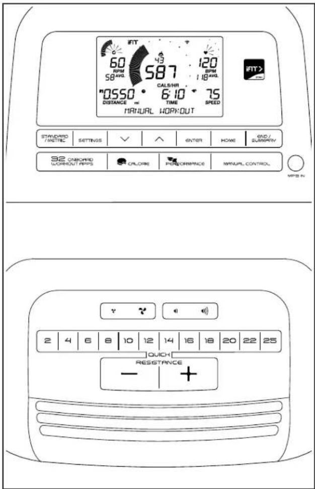
FEATURES OF THE CONSOLE
The advanced console offers an array of features designed to make your workouts more effective and enjoyable.
When you use the manual mode of the console, you can change the resistance of the pedals with the touch of a button.
While you exercise, the console will display continuous exercise feedback. You can even measure your heart rate using the handgrip heart rate monitor or a compatible heart rate monitor. See page 20 for information about purchasing an optional chest heart rate monitor.
You can also connect your tablet to the console and use the iFit®—Smart Cardio Equipment app to record and track your workout information.
The console also offers a selection of onboard workouts. Each workout automatically changes the resistance of the pedals as it guides you through an effective workout.
You can even connect your personal audio player to the console sound system and listen to your favorite music or audio books while you exercise.
To use the manual mode, see page 16. To use an onboard workout, see page 18. To connect your tablet to the console, see page 19. To connect your heart rate monitor to the console, see page 19. To use the sound system, see page 20. To change console settings, see page 20.
Note: If there is a sheet of plastic on the display, remove the plastic.
Note: The console can display speed and distance in either miles or kilometers. To change the unit of measurement, press the Standard/Metric button repeatedly. For simplicity, all instructions in this section refer to miles.
HOW TO USE THE MANUAL MODE
1. Turn on the console.
Begin pedaling or press any button on the console to turn on the console.
When you turn on the console, the displays will turn on, a tone will sound, and the console will be ready for use.
2. Select the manual mode.
Press the Manual Control button to select the manual mode.
3. Change the resistance of the pedals as desired.
As you pedal, change the resistance of the pedals by pressing the Quick Resistance increase and decrease buttons or by pressing one of the numbered Quick Resistance buttons.
Note: After you press a button, it will take a moment for the pedals to reach the selected resistance level.
4. Follow your progress with the displays.
The display can show the following workout information:
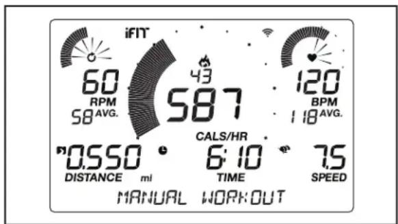
Calories (flame icon)—When the manual mode is selected, this display will show the approximate number of calories you have burned. When an onboard workout is selected, this display will show either the approximate number of calories remaining to be burned or the approximate number of calories you have burned.
Calories per Hour (Cals/Hr)—This display will show the approximate number of calories you are burning per hour.
Distance—This display will show the distance that you have pedaled in miles (mi) or kilometers (km).
Pulse (BPM)—This display will show your heart rate in beats per minute (bpm) when you use the handgrip heart rate monitor or the optional chest heart rate monitor (see step 5).
Pulse Average (BPM AVG)—This display will show your average heart rate in beats per minute (bpm) when you use the handgrip heart rate monitor or the optional chest heart rate monitor (see step 5).
Resistance—This display will show the resistance level of the pedals for a few seconds each time the resistance level changes.
RPM—This display will show your pedaling speed in revolutions per minute (rpm).
RPM Average (RPM AVG)—This display will show your average pedaling speed in revolutions per minute (rpm).
Speed—This display will show your pedaling speed in miles per hour or kilometers per hour. To change the unit of measurement, press the Standard/Metric button repeatedly.
Time—When the manual mode is selected, this display will show the elapsed time. When an onboard workout is selected, this display will show either the time remaining in the workout or the elapsed time.
Watts—This display will show your approximate power output in watts.
Average Watts (AVG)—This display will show your approximate average power output in watts for the workout.
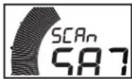
Scan Mode and Priority
Mode—The calories and watts displays will appear in an alternating cycle (scan mode). To select either the calories
or the watts display for continuous display (priority mode), press the increase or decrease button next to the Enter button repeatedly until the desired display appears. To return to the scan mode, press the increase button repeatedly until the word SCAN appears.
Press the Home button to exit the workout and return to the main menu. If necessary, press the Home button again.
Press the End/Summary button to end the work-out and view a workout summary. The workout summary will appear in the displays for several seconds.
Change the volume level of the console by pressing the volume increase and decrease buttons.
5. Measure your heart rate if desired.
You can measure your heart rate using either the handgrip heart rate monitor or an optional chest heart rate monitor (see page 20 for information about the optional chest heart rate monitor). Note: The console is compatible with BLUETOOTH® Smart heart rate monitors.
Note: If you use both heart rate monitors at the same time, the chest heart rate monitor will have priority.
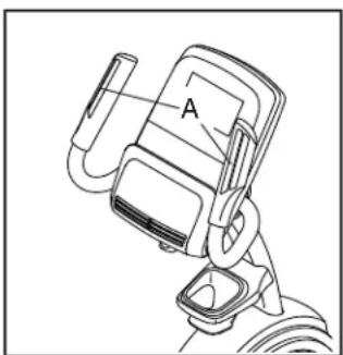
If there are sheets
of plastic on the metal contacts (A) on the hand-grip heart rate monitor, remove the plastic. To measure your heart rate, hold the handgrip heart rate monitor with your
natural_image
Line drawing of a car front-mounted device with labeled component 'A' (no text or symbols beyond label)palms resting against the contacts. Avoid moving your hands or gripping the contacts tightly.
When your pulse is detected, your heart rate will appear in the display. For the most accurate heart rate reading, hold the contacts for at least 15 seconds.
6. Turn on the fan if desired.
The fan has several speed settings, including an auto mode. While the auto mode is selected, the speed of the fan will automatically increase or decrease as your exercise intensity increases or decreases. Press the fan increase and decrease buttons repeatedly to select a fan speed or to turn off the fan.
Note: If the pedals do not move for about 30 seconds, the fan will turn off automatically.
7. When you are finished exercising, the console will turn off automatically.
If the pedals do not move for several seconds, a series of tones will sound, the console will pause, and the display will pause.
If the pedals do not move for several minutes, the console will turn off and the display will be reset.
Note: The console features a display demo mode, designed to be used if the elliptical is displayed in a store. When the demo mode is turned on, the console will show a preset presentation. To turn off the demo mode, see HOW TO CHANGE CONSOLE SETTINGS on page 20.
HOW TO USE AN ONBOARD WORKOUT
1. Turn on the console.
Begin pedaling or press any button on the console to turn on the console.
When you turn on the console, the displays will turn on, a tone will sound, and the console will be ready for use.
2. Select an onboard workout.
To select an onboard workout, press the desired Workout Apps button repeatedly until the desired workout appears in the display.
When you select an onboard workout, the display will show the name of the workout and the duration of the workout or the number of calories to be burned.
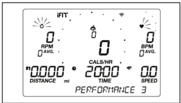
The maximum speed and the maximum resistance level for the workout will also appear in the display.
3. Begin pedaling to start the workout.
Each workout is divided into one-minute segments. One resistance level and one target speed is programmed for each segment. Note: The same resistance level and/or target speed may be programmed for consecutive segments.
At the end of each segment of the workout, a series of tones will sound. If a different resistance level and/or target speed is programmed for the
next segment, the resistance level and/or target speed will appear in the display to alert you. The resistance of the pedals will then change.
As you exercise, keep your pedaling speed near the target speed for the current segment.
IMPORTANT: The target speed is intended only to provide motivation. Your actual pedaling speed may be slower than the target speed. Make sure to pedal at a speed that is comfortable for you.
If the resistance level for the current segment is too high or too low, you can manually override the setting by pressing the Quick Resistance buttons. IMPORTANT: When the current segment of the workout ends, the pedals will automatically adjust to the resistance level programmed for the next segment.
The workout will continue in this way until the last segment ends. To pause the workout at any time, stop pedaling. The time will flash in the display. To resume the workout, simply resume pedaling.
To end the workout, press the End/Summary button. A summary of the workout will appear in the displays for several seconds.
4. Follow your progress with the displays.
See step 4 on page 16.
5. Measure your heart rate if desired.
See step 5 on page 17.
6. Turn on the fan if desired.
See step 6 on page 17
7. When you are finished exercising, the console will turn off automatically.
See step 7 on page 17.
HOW TO CONNECT YOUR TABLET TO THE CONSOLE
The console supports BLUETOOTH connections to tablets via the iFit–Smart Cardio Equipment app and to compatible heart rate monitors. Note: Other BLUETOOTH connections are not supported.
1. Download and install the iFit–Smart Cardio Equipment app on your tablet.
On your iOS ^® or Android ^TM tablet, open the App Store ^SM or the Google Play ^TM store, search for the free iFit–Smart Cardio Equipment app, and then install the app on your tablet. Make sure that the BLUETOOTH option is enabled on your tablet.
Then, open the iFit–Smart Cardio Equipment app and follow the instructions to set up an iFit account and customize settings.
2. Connect your heart rate monitor to the console if desired.
If you are connecting both your heart rate monitor and your tablet to the console, you must connect your heart rate monitor before you connect your tablet. See HOW TO CONNECT YOUR HEART RATE MONITOR TO THE CONSOLE at the right.
3. Connect your tablet to the console.
Press the iFit Sync button on the console; the console pairing number will appear in the display. Then, follow the instructions in the iFit–Smart Cardio Equipment app to connect your tablet to the console.
When a connection is established, the LED on the console will turn solid blue.
4. Record and track your workout information.
Follow the instructions in the iFit–Smart Cardio Equipment app to record and track your workout information.
5. Disconnect your tablet from the console if desired.
To disconnect your tablet from the console, first select the disconnect option in the iFit–Smart Cardio Equipment app. Then, press and hold the iFit Sync button on the console until the LED on the console turns solid green.
Note: All BLUETOOTH connections between the console and other devices (including any tablets, heart rate monitors, and so forth) will be disconnected.
HOW TO CONNECT YOUR HEART RATE MONITOR TO THE CONSOLE
The console is compatible with all BLUETOOTH Smart heart rate monitors.
To connect your BLUETOOTH Smart heart rate monitor to the console, press the iFit Sync button on the console; the console pairing number will appear in the display. When a connection is established, the LED on the console will flash red twice.
Note: If there is more than one compatible heart rate monitor near the console, the console will connect to the heart rate monitor with the strongest signal.
To disconnect your heart rate monitor from the console, press and hold the iFit Sync button on the console until the LED on the console turns solid green.
Note: All BLUETOOTH connections between the console and other devices (including any tablets, heart rate monitors, and so forth) will be disconnected.
HOW TO USE THE SOUND SYSTEM
To play music or audio books through the console sound system while you exercise, plug a 3.5 mm male to 3.5 mm male audio cable (not included) into the jack on the console and into a jack on your personal audio player; make sure that the audio cable is fully plugged in. Note: To purchase an audio cable, see your local electronics store.
Next, press the play button on your personal audio player. Adjust the volume level using the volume increase and decrease buttons on the console or the volume control on your personal audio player.
THE OPTIONAL CHEST HEART RATE MONITOR
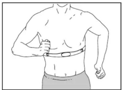
Whether your goal is to burn fat or to strengthen your cardiovascular system, the key to achieving the best results is to maintain the proper heart rate during your
natural_image
Line drawing of a person wearing a chest with a bandage (no text or symbols)workouts. The optional chest heart rate monitor will enable you to continuously monitor your heart rate while you exercise, helping you to reach your personal fitness goals. To purchase a chest heart rate monitor, please see the front cover of this manual.
Note: The console is compatible with all BLUETOOTH Smart heart rate monitors.
HOW TO CHANGE CONSOLE SETTINGS
1. Select the settings mode.
To select the settings mode, press the Settings button. The settings information will appear in the display.
2. Navigate the settings mode.
While the settings mode is selected, the display will show several optional screens. Press the increase and decrease buttons near the Enter button repeatedly to select the desired optional screen.
The lower section of the display will show instructions for the selected screen. Make sure to follow the instructions shown in the lower part of the display.
3. Change settings as desired.
Units—The currently selected unit of measurement will appear in the display. To change the unit of measurement, press the Enter button repeatedly. To view distance in miles, select ENGLISH. To view distance in kilometers, select METRIC.
Contrast Level—The currently selected contrast level will appear in the display. Press the Quick Resistance increase and decrease buttons to adjust the contrast level.
Usage Information—The display will show the total number of hours that the exercise bike has been used and the total distance (in miles or kilometers) that has been pedaled on the exercise bike.
Demo—The console features a display demo mode, designed to be used if the elliptical is displayed in a store. Press the Quick Resistance increase button repeatedly to turn the demo mode on or off.
4. Exit the settings mode.
Press the Settings button to exit the settings mode.
MAINTENANCE AND TROUBLESHOOTING
MAINTENANCE
Regular maintenance is important for optimal performance and to reduce wear. Inspect and properly tighten all parts each time the exercise bike is used. Replace any worn parts immediately.
To clean the exercise bike, use a damp cloth and a small amount of mild soap. IMPORTANT: To avoid damage to the console, keep liquids away from the console and keep the console out of direct sunlight.
CONSOLE TROUBLESHOOTING
If the console does not turn on, make sure that the power adapter is fully plugged in.
If the console does not display your heart rate when you use the handgrip heart rate monitor, see step 5 on page 17.
If a replacement power adapter is needed, call the telephone number on the cover of this manual. IMPORTANT: To avoid damaging the console, use only a manufacturer-supplied regulated power adapter.
HOW TO ADJUST THE DRIVE BELT
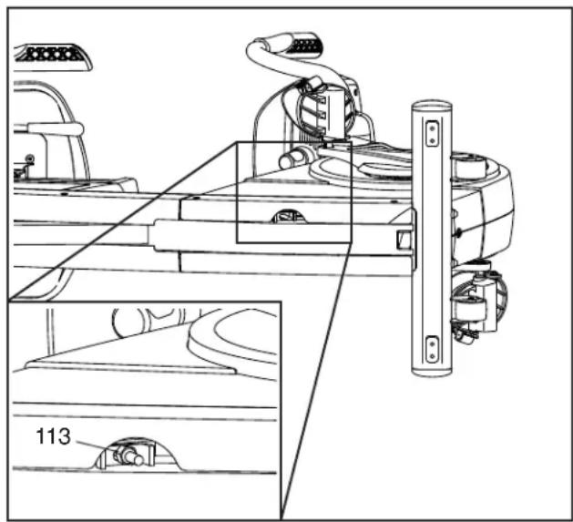
If the pedals slip while you are pedaling, even while the resistance is adjusted to the highest setting, the drive belt may need to be adjusted. Before you adjust the drive belt, unplug the power adapter.
With the help of a second person, carefully lay the exercise bike on its side.
Next, tighten the indicated M8 Hex Nut (113) slightly to tighten the Drive Belt (not shown). Then, with the help of a second person, return the exercise bike to the upright position. Plug in the power adapter.
natural_image
Technical line drawing of a mechanical assembly with component details (no readable text or symbols)Repeat this process, if necessary, until the pedals no longer slip.
HOW TO ADJUST THE REED SWITCH
If the console does not display correct feedback, the reed switch should be adjusted. Before you adjust the reed switch, unplug the power adapter.
Using a small standard screwdriver, carefully pry the left Crank Cover (25) off the left Shield Cover (24). Next, remove the two M5 x 20mm Screws (53). Then, rotate the left Shield Cover out of the way.
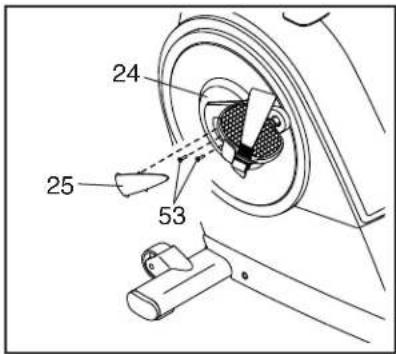
Note: For clarity, the left pedal and the left shield cover are shown removed in the drawing at the right.
Locate the Reed Switch (35). Rotate the Left Crank Arm (100) until a Magnet (39) is aligned with the Reed Switch. Next, loosen the Clamp Screw (A), slide the Reed Switch slightly toward or away from the Magnet, and then retighten the Clamp Screw.
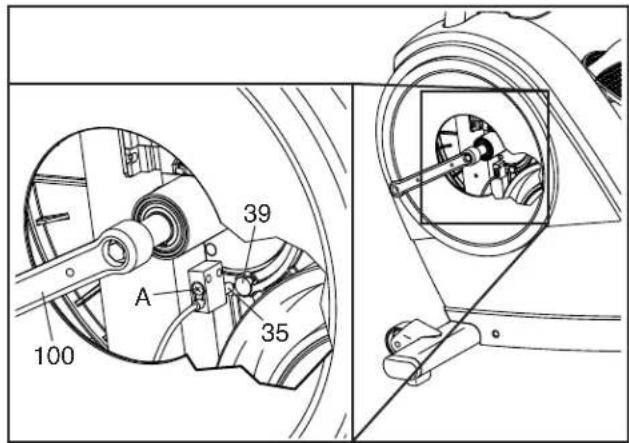
Plug in the power adapter and rotate the Left Crank Arm (100) for a moment. Repeat these actions until the console displays correct feedback.
When the reed switch is correctly adjusted, reattach the parts that you removed.
EXERCISE GUIDELINES
WARNING: Before beginning this or any exercise program, consult your physician. This is especially important for persons over age 35 or persons with pre-existing health problems.
The heart rate monitor is not a medical device. Various factors may affect the accuracy of heart rate readings. The heart rate monitor is intended only as an exercise aid in determining heart rate trends in general.
These guidelines will help you to plan your exercise program. For detailed exercise information, obtain a reputable book or consult your physician. Remember, proper nutrition and adequate rest are essential for successful results.
EXERCISE INTENSITY
Whether your goal is to burn fat or to strengthen your cardiovascular system, exercising at the proper intensity is the key to achieving results. You can use your heart rate as a guide to find the proper intensity level. The chart below shows recommended heart rates for fat burning and aerobic exercise.
| 165 | 155 | 145 | 140 | 130 | 125 | 115 | |
| 145 | 138 | 130 | 125 | 118 | 110 | 103 | |
| 125 | 120 | 115 | 110 | 105 | 95 | 90 | |
| 20 | 30 | 40 | 50 | 60 | 70 | 80 |
To find the proper intensity level, find your age at the bottom of the chart (ages are rounded off to the nearest ten years). The three numbers listed above your age define your “training zone.” The lowest number is the heart rate for fat burning, the middle number is the heart rate for maximum fat burning, and the highest number is the heart rate for aerobic exercise.
Burning Fat—To burn fat effectively, you must exercise at a low intensity level for a sustained period of time. During the first few minutes of exercise, your body uses carbohydrate calories for energy. Only after the first few minutes of exercise does your body begin to use stored fat calories for energy. If your goal is to burn fat, adjust the intensity of your exercise until your heart rate is near the lowest number in your training zone. For maximum fat burning, exercise with your heart rate near the middle number in your training zone.
Aerobic Exercise—If your goal is to strengthen your cardiovascular system, you must perform aerobic exercise, which is activity that requires large amounts of oxygen for prolonged periods of time. For aerobic exercise, adjust the intensity of your exercise until your heart rate is near the highest number in your training zone.
WORKOUT GUIDELINES
Warming Up—Start with 5 to 10 minutes of stretching and light exercise. A warm-up increases your body temperature, heart rate, and circulation in preparation for exercise.
Training Zone Exercise—Exercise for 20 to 30 minutes with your heart rate in your training zone. (During the first few weeks of your exercise program, do not keep your heart rate in your training zone for longer than 20 minutes.) Breathe regularly and deeply as you exercise; never hold your breath.
Cooling Down—Finish with 5 to 10 minutes of stretching. Stretching increases the flexibility of your muscles and helps to prevent post-exercise problems.
EXERCISE FREQUENCY
To maintain or improve your condition, complete three workouts each week, with at least one day of rest between workouts. After a few months of regular exercise, you may complete up to five workouts each week, if desired. Remember, the key to success is to make exercise a regular and enjoyable part of your everyday life.
PART LIST
Key No. Qty. Description
| 1 | 1 | Frame |
| 2 1 | Front Stabilizer | |
| 3 1 | Rear Stabilizer | |
| 4 | 1 | Upright |
| 5 | 1 | Console |
| 6 1 | Left Handlebar | |
| 7 1 | Left Pulse Sensor/Wire | |
| 8 1 | Right Pulse Sensor/Wire | |
| 9 1 | Accessory Tray | |
| 10 | 1 | Rail |
| 11 1 | Seat Carriage | |
| 12 | 1 | Seat |
| 13 | 1 | Backrest |
| 14 1 | Backrest Frame | |
| 15 1 | Seat Handle | |
| 16 1 | Seat Lever | |
| 17 1 | Brake Bracket | |
| 18 1 | Seat Handlebar | |
| 19 1 | Upright Cover | |
| 20 1 | Upper Bracket Cover | |
| 21 1 | Left Shield | |
| 22 1 | Right Shield | |
| 23 2 | Lock Ring | |
| 24 2 | Shield Cover | |
| 25 2 | Crank Cover | |
| 26 2 | Rear Stabilizer Cap | |
| 27 2 | Stabilizer Foot | |
| 28 2 | Leveling Foot | |
| 29 1 | Right Pedal/Strap | |
| 30 1 | Left Pedal/Strap | |
| 31 1 | Eddy Mechanism | |
| 32 | 1 | Idler |
| 33 1 | Resistance Motor | |
| 34 1 | Resistance Cable | |
| 35 1 | Reed Switch/Wire | |
| 36 11 | M4 x 19mm Screw | |
| 37 | 1 | Clamp |
| 38 2 | Crank Bearing | |
| 39 | 2 | Magnet |
| 40 | 1 | Pulley |
| 41 1 | Main Wire | |
| 42 1 | M6 x 50mm Screw | |
| 43 1 | Right Rear Shield | |
| 44 2 | M10 x 120mm Screw | |
| 45 1 | Idler Screw | |
| 46 1 | Left Rear Shield | |
| 47 7 | M8 x 20mm Screw | |
| 48 1 | M8 Thin Washer | |
| 49 2 | M8 x 50mm Bolt |
Key No. Qty. Description
| 50 | 2 | M10-1.0 Flange Nut |
| 51 | 8 | M6 x 30mm Screw |
| 52 | 20 | M4 x 25mm Screw |
| 53 | 4 | M5 x 20mm Screw |
| 54 | 2 | M10 x 55mm Screw |
| 55 | 4 | Resistance Motor Screw |
| 56 | 4 | M8 x 40mm Screw |
| 57 | 2 Wheel | |
| 58 | 1 | Power Wire |
| 59 | 1 | Drive Belt |
| 60 | 4 | M10 x 20mm Screw |
| 61 | 1 | M4 x 19mm Bright Screw |
| 62 | 6 | M6 x 10mm Screw |
| 63 | 23 | M4 x 15mm Screw |
| 64 | 1 | Rear Rail Cover |
| 65 | 1 | Front Rail Cover |
| 66 | 4 Bumper | |
| 67 | 8 | M6 x 20mm Screw |
| 68 | 13 | M6 Small Washer |
| 69 | 2 | Upper Roller |
| 70 | 4 | Lower Roller |
| 71 | 2 Axle | |
| 72 | 1 Brake | |
| 73 | 1 | Brake Block |
| 74 | 3 | M10 Locknut |
| 75 | 2 | M10 x 45mm Screw |
| 76 | 5 | M6 Split Washer |
| 77 | 2 | Brake Spacer |
| 78 | 1 Grommet | |
| 79 | 1 | Accessory Tray Bracket |
| 80 | 1 | Lower Bracket Cover |
| 81 | 1 | Right Handlebar |
| 82 | 1 | Console Bracket |
| 83 | 1 | Adjustment Knob |
| 84 | 1 | Upright Bracket |
| 85 | 1 | Upper Block |
| 86 | 1 | Lower Block |
| 87 | 2 | Console Bracket Bushing |
| 88 | 2 | Upright Bracket Bushing |
| 89 | 4 | M8 x 14mm Screw |
| 90 | 1 | Right Seat Handgrip |
| 91 | 1 | Pivot Axle |
| 92 | 2 | M8 Large Washer |
| 93 | 1 | Left Seat Handgrip |
| 94 | 6 | M8 x 13mm Screw |
| 95 | 6 | M8 Nut |
| 96 | 1 | M10 x 130mm Bolt |
| 97 | 2 | M10 Flange Nut |
| 98 | 1 | M8 Washer |
Key No. Qty. Description
| 99 | 1 | Right Crank Arm |
| 100 | 1 | Left Crank Arm |
| 101 | 2 | M10 x 60mm Bolt |
| 102 | 7 | M8 Locknut |
| 103 | 3 | M6 x 15mm Screw |
| 104 | 2 | Crank Snap Ring |
| 105 | 1 Crank | |
| 106 | 1 | Frame Cap |
| 107 | 1 | Power Adapter |
Key No. Qty. Description
| 108 | 4 | M8 Split Washer |
| 109 | 2 | Front Stabilizer Cap |
| 110 | 2 | M10 x 96mm Screw |
| 111 | 4 | M4 x 30mm Screw |
| 112 | 8 | M6 Washer |
| 113 | 1 | M8 Hex Nut |
| * | - | User's Manual |
| * | - | Assembly Tool |
Note: Specifications are subject to change without notice. For information about ordering replacement parts, see the back cover of this manual. *These parts are not illustrated.
- NordicTrack® C VR 21
- ACTIVATE YOUR WARRANTY
- CUSTOMER SERVICE
- CAUTION
- USER'S MANUAL
- TABLE OF CONTENTS
- WARNING DECAL PLACEMENT
- IMPORTANT PRECAUTIONS
- PROTECT
- PLAN FEATURES
- BEFORE YOU BEGIN
- PART IDENTIFICATION CHART
- ASSEMBLY
- Gotoiconservice.ca/CustomerService/registration and register your product.
- HOW TO USE THE EXERCISE BIKE
- HOW TO PLUG IN THE POWER ADAPTER
- HOW TO MOVE THE EXERCISE BIKE
- HOW TO ADJUST THE ANGLE OF THE CONSOLE
- HOW TO ADJUST THE SEAT
- HOW TO ADJUST THE PEDAL STRAPS
- CONSOLE DIAGRAM
- FEATURES OF THE CONSOLE
- HOW TO USE THE MANUAL MODE
- Turn on the console.
- Select the manual mode.
- Change the resistance of the pedals as desired.
- Follow your progress with the displays.
- Scan Mode and Priority
- Measure your heart rate if desired.
- If there are sheets
- Turn on the fan if desired.
- When you are finished exercising, the console will turn off automatically.
- HOW TO USE AN ONBOARD WORKOUT
- Select an onboard workout.
- Begin pedaling to start the workout.
- HOW TO CONNECT YOUR TABLET TO THE CONSOLE
- Download and install the iFit–Smart Cardio Equipment app on your tablet.
- Connect your heart rate monitor to the console if desired.
- Connect your tablet to the console.
- Record and track your workout information.
- Disconnect your tablet from the console if desired.
- HOW TO CONNECT YOUR HEART RATE MONITOR TO THE CONSOLE
- HOW TO USE THE SOUND SYSTEM
- THE OPTIONAL CHEST HEART RATE MONITOR
- HOW TO CHANGE CONSOLE SETTINGS
- Select the settings mode.
- Navigate the settings mode.
- Change settings as desired.
- Exit the settings mode.
- MAINTENANCE AND TROUBLESHOOTING
- MAINTENANCE
- CONSOLE TROUBLESHOOTING
- HOW TO ADJUST THE DRIVE BELT
- HOW TO ADJUST THE REED SWITCH
- EXERCISE GUIDELINES
- EXERCISE INTENSITY
- WORKOUT GUIDELINES
- EXERCISE FREQUENCY
- PART LIST
Brand : NordicTrack
Model : VR21
Category : Exercise bike