
N4400 - Saw Hammer - Free user manual and instructions
Find the device manual for free N4400 Hammer in PDF.


| Product Type | Bandsaw |
| Brand | Hammer |
| Model | N4400 |
| Dimensions (HxWxD) | 1900 x 800 x 650 mm |
| Package Dimensions (HxWxD) | 1900 x 780 x 660 mm |
| Net Weight | 140 kg |
| Cutting Height | 275 mm |
| Rip Capacity | 420 mm (370 mm with parallel fence) |
| Saw Blade Length | 3950 - 4000 mm |
| Saw Blade Width | 6 - 20 mm |
| Saw Blade Speed | 20 m/min |
| Wheel Diameter | 440 mm |
| Table Size (WxD) | 420 x 575 mm (at 950 mm height) |
| Table Tilt | Left 10°, Right 22.5° |
| Noise Emission (L Aeq) | 84.7 dB(A) |
| Dust Extraction Connection | Ø 120 mm |
| Required Air Speed | 20 m/s |
| Minimum Depression | 773 Pa |
| Volume Flow | 814 m³/h |
| Electrical Connection | 230V or 400V, 3-phase (depending on version) |
| Safety Features | Emergency stop, wheel door safety switches, blade guard, tension indicator |
| Included Accessories | Parallel cutting fence, mitre fence, table insert, push stick |
| Construction | Steel base frame, cast iron wheels |
| Maintenance | Regular cleaning of sawdust, check belt tension, lubricate only bearing surfaces |
Frequently Asked Questions - N4400 Hammer
User questions about N4400 Hammer
0 question about this device. Answer the ones you know or ask your own.
Ask a new question about this device
Download the instructions for your Saw in PDF format for free! Find your manual N4400 - Hammer and take your electronic device back in hand. On this page are published all the documents necessary for the use of your device. N4400 by Hammer.
USER MANUAL N4400 Hammer
natural_image
Industrial machine labeled 'N4400' with visible hammer branding, no readable text beyond brandingKeep this manual handy and in good condition for continual reference!

Attention: Upon arrival, the machine must be inspected immediately. If the machine was damaged during transport or if parts are missing, a written record of the problems must be submitted to the forwarding agent and a damage report must be drawn up. Be sure to also notify your supplier straight away.

For the safety of all personnel, it is necessary to conscientiously study this manual before assembling and putting the machine into operation. This manual must be kept in good condition, as it is considered to be a part of the machine. Furthermore, keep the manual handy in the vicinity of the machine so that it is accessible to personnel when they are using, maintaining or repairing the machine.
HAMMER | A product of the FELDER GROUP
© Felder KG
KR-FELDER-STR 1
A-6060 Hall in Tirol
Tel.: +43 (0) 5223 45 0 90
Fax.: +43 (0) 5223 45 0 99
1.1 Explanations of the symbols....5
1.2 Information regarding the manual ....5
1.3 Liability and warranty....6
1.4 Copyright....6
1.6 Spare parts ....6
1.7 Disposal....7
2 Safety 8
2.1 Intended use....8
2.2 Manual contents 8
2.3 Making changes and modifications to the machine....8
2.4 Responsibilities of the operator....9
2.5 What is required of the personnel 9
2.6 Work safety 9
2.7 Personal safety....10
2.8 Hazards arising from the machine....10
2.9 Other risks 10
3 Declaration of Conformity 11
4 Technical data 12
4.1 Dimensions and weight....12
4.2 Operation and storage conditions 12
4.3 Electrical connection....12
4.4 Noise emissions....13
4.5 Dust extraction....14
5. Setting up the machine 15
5.1 Overview....15
5.2 Data plate....16
6 Setup and installation 17
6.1 Safety instructions .... 17
6.2 Positioning 17
6.2.1 Safety instructions .... 18
6.2.2 Setting up the work table 18
7 Operation 19
7.1 Safety instructions....19
7.2 Switching on the machine 20
7.3 Authorised work techniques....20
7.4 Authorised work techniques....21
7.4.1 Positioning the 90° end stop on the work table .....21
7.4.2 Parallel cutting fence....21
7.4.3 Saw blade replacement/tension 22
7.4.4 Longitudinal cut along the marked line 22
7.4.5 Cutting round work-pieces in the transverse direction 23
7.4.6 Longitudinal cut of narrow or thin work-pieces with the guide fence 23
Table of Contents
7.4.7 Cutting work-pieces on the upright edge 23
7.4.8 Angular cuts....24
7.4.9 Circular cuts 24
7.4.10 Diagonal cross cuts of rectangular work-pieces....24
7.5 Applications....25
7.5.1 Blade selection and maintenance 25
7.5.2 Adjusting the saw blade guide 26
7.5.2.1 Upper blade guide....26
7.5.2.2 Lower blade guide 26
8. Maintenance 27
8.1 Safety instructions 27
8.2 Cleaning and lubrication....27
8.3 Drive belts....28
8.3.1 Adjusting the belt tension 28
9 Faults 29
9.1 Safety instructions ....29
9.2 What to do in case of a fault....29
9.3 What to do after rectifying the fault....29
9.4 Faults, causes and repairs ....30
10 Circuit diagram 32
10.1 Safety instructions 32
11 Spare parts 34
11.1 Machine base-frame....34
11.2 Machine table 35
11.3 Height adjustable protection device 36
11.4 Upper wheel 37
11.5 Lower wheel 38
11.6 Safety equipment....39
12 Index 40
1 General
1.1 Explanations of the symbols
Important technical safety instructions in this manual are marked with symbols.
These instructions for work safety must be followed. In all these particular cases, special attention must be paid in order to avoid accidents, injury to persons or material damage.

Warning: Risk of injury or death!
This symbol marks instructions that must be followed in order to avoid harm to one's health, injuries, permanent impairment or death.
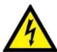
Warning: Danger – electric current!
This symbol warns of potentially dangerous situations related to electric current. Not observing the safety instructions increases the risk of serious injury or death. Required electrical repairs may only be carried out by a trained electrical technician.

Attention: Risk of material damage!
This symbol marks instructions which, if not observed, may lead to material damage, functional failures and/or machine breakdown.

Attention:
This symbol marks tips and information which should be observed to ensure efficient and failure-free operation of the machine.
1.2 Information regarding the manual
This manual describes how to operate the machine properly and safely. Be sure to follow the safety tips and instructions stated herein as well as any local accident prevention directives and general safety regulations. Before beginning any work on the machine, ensure that the manual, in particular the chapter entitled „Safety“ and the respective safety guidelines, has been read in its entirety and fully understood. This manual is an integral part of the machine; therefore, it must be kept in the vicinity of the machine and accessible at all times. If the machine is sold, rented, lent or otherwise transferred to another party, the manual must accompany the machine.
1.3 Liability and warranty
The contents and instructions in this manual were compiled in consideration of current regulations and state of the art technology as well as based on our know-how and experience acquired over many years. This manual must be read carefully before commencing any work on or with this machine. The manufacturer shall not be liable for damages and faults resulting from the disregard of instructions in the manual. The texts and images do not necessarily represent the delivery contents. The images and graphics are not depicted on a scale of 1:1. The
actual delivery contents are dependent on custom-build specifications, add-on options or recent technical modifications and may therefore deviate from the descriptions, instructions and images contained in the manual. Should any questions arise, please contact the manufacturer. We reserve the right to make technical modifications to the product in order to further improve user-friendliness and develop its functionality.
1.4 Copyright
This manual should be handled confidentially. It is designated solely for those persons who work on or with the machine. All descriptions, texts, drawings, photos and other depictions are protected by copyright and other commercial laws. Illegal use of the materials is punishable by law.
This manual – in its entirety or parts thereof – may not be transferred to third parties or copied in any way or
form, and its contents may not be used or otherwise communicated without the express written consent of the manufacturer.
Infringement on these rights may lead to a demand for compensation or other applicable claims. We reserve all rights in exercising commercial protection laws.
1.5 Warranty notice
The guarantee period is in accordance with national guidelines and details can be found within our website, www.felder-group.com
1.6 Spare parts

Attention: Employing counterfeit or faulty spare parts may lead to damage, malfunctions or complete breakdown of the machine.
If unauthorized spare parts are installed in the machine, all warranty, service, compensation and liability claims against the manufacturer and their contractors, dealers
and representatives shall be rejected. Use only original spare parts from the manufacturer.

Attention: A list of authorised original spare parts can be found at the end of this operating manual.
1.7 Disposal
If the machine is to be disposed of, separate the components into the various material groups in order to allow them to be reused or selectively disposed of. The whole structure is made of steel and can therefore be separated without any problem. This material is also easy to dispose of and does not pollute the environment
or jeopardise people's health. International environmental regulations and local disposal laws must always be complied with.

Attention: Used electrical materials, electronic components, lubricants and other auxiliary substances must be treated as hazardous waste and may only be disposed of by specialized, licensed firms.
2 Safety
At the time of its development and production, the machine was built in accordance with prevailing technological regulations and therefore conforms to industry safety standards.
However, hazards may arise should the machine be operated by untrained personnel, used improperly or employed for purposes other than those it was designed for. The chapter entitled „Safety“ offers an overview of all the important safety considerations necessary to optimise safety and ensure the safe and trouble-free operation of the machine.
Additionally, in order to further minimize risks, the other chapters of this manual contain specific safety instructions, all marked with symbols. Besides the various instructions, there are a number of pictograms, signs and labels affixed to the machine that must also be heeded. These must be kept visible and readable and may not be removed.
2.1 Intended use
The N4400 bandsaw is solely for the use of sawing wood and other similar machinable materials. The machine should only be used to cut wood and wood-like panels. Operational safety is guaranteed only when the machine is used for the intended purposes.

Attention: Any other application above and beyond the intended purposes is considered improper use and is therefore not permitted. All claims regarding damage resulting from improper use that are made against the manufacturer and its authorized representatives shall be rejected. The operator shall be solely liable for any damage that results from improper use of the machine.
The term „proper use“ also refers to correctly observing the operating conditions as well as the specifications and instructions in this manual.
The machine may only be operated with parts and original accessories from the manufacturer.
2.2 Manual contents
All those appointed to work on or with the machine must have fully read and understood the manual before commencing any work. This requirement must be met even if the appointed person is familiar with the operation of such a machine or a similar one, or has been trained by the manufacturer. Knowledge about the contents of this manual is a prerequisite for protecting personnel
from hazards and avoiding mistakes so that the machine may be operated in a safe and trouble-free manner. It is recommended that the operator request proof from the personnel that the contents of the manual have in fact been read and understood.
2.3 Making changes and modifications to the machine
In order to minimize risks and to ensure optimal performance, it is strictly prohibited to alter, retrofit or modify the machine in any way without the express consent of the manufacturer. All the pictograms, signs and labels affixed to the machine must be kept visible, readable and may not be removed. Pictograms, signs and labels that have become damaged or unreadable must be replaced promptly.
2.4 Responsibilities of the operator
This manual must be kept in the immediate vicinity of the machine and be accessible at all times to all persons working on or with the machine. The machine may only be operated if it is in proper working order and in safe condition. Every time before the machine is switched on, it must be inspected for visible defects and general intactness. All instructions in this manual must be strictly followed without reservation.
Besides the safety advice and instructions stated in this manual, it is necessary to consider and observe local accident prevention regulations, general safety regulations
2.5 What is required of the personnel
Only authorized and trained personnel may work on and with the machine. The personnel must be briefed about all functions and potential dangers of the machine. "Specialist staff" is a term that refers to those who – due to their professional training, know-how, experience, and knowledge of relevant regulations – are in a position to assess delegated tasks and recognise potential risks. If the personnel lack the necessary knowledge for working on or with the machine, they must first be trained. Responsibility for working with the machine (installation, service, maintenance, overhaul) must be clearly defined and strictly observed. Only those persons who can be expected to carry out their work reliably may be given permission to work on or with the machine. Personnel
2.6 Work safety
Following the safety advice and instructions given in this manual can prevent bodily injury and material damage while working on and with the machine. Failure to observe these instructions can lead to bodily injury and damage to or destruction of the machine. Disregard of the safety advice and instructions given in this manual as as well as current environmental stipulations that apply to the operational range of the machine.
The operator and designated personnel are responsible for the trouble-free operation of the machine as well as for clearly establishing who is in charge of installing, servicing, maintaining and cleaning the machine. Machines, tools and accessories must be kept out of the reach of children.
must refrain from working in ways that could harm others, the environment or the machine itself. It is absolutely forbidden for persons who are under the influence of drugs, alcohol or reaction-impairing medication to work on or with the machine. When appointing personnel to work on the machine, it is necessary to observe all local regulations regarding age and professional status. The user is also responsible for ensuring that unauthorised persons remain at a safe distance from the machine. The personnel are obliged to immediately report to the operator any irregularities with the machine that might compromise safety.
well as the accident prevention regulations and general safety regulations applicable to the operative range of the machine shall release the manufacturer and their authorised representatives from any and all liability and compensation claims.
2.7 Personal safety
When working on or with the machine, the following must be strictly observed:

Persons with long hair who are not wearing a hairnet are not permitted to work on or with the machine.
When working on or with the machine, the following must always be worn by personnel:
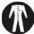
Protective gear (overalls, safety goggles, dust mask, hairnet to contain long hair, etc.). Sturdy, tight-fitting clothing (tear-resistant, no wide sleeves).

Protective footwear That protects the feet from heavy falling objects and prevents sliding on slippery floors.

Ear protection To protect against loss of hearing.
2.8 Hazards arising from the machine
The machine has undergone a hazards analysis. The design and construction of the machine are based on the results of this analysis and correspond to state-of-the-art technology.
The machine is considered operationally safe when used
properly. Nevertheless, there are some residual risks that must be considered. The machine runs with high electrical voltage.
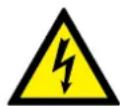
Warning! Danger – electric current: Electrical energy can cause serious bodily injury. Damaged insulation materials or defective individual components can cause a life-threatening electrical shock.
- Before carrying out any maintenance, cleaning and repair work, switch off the machine and secure it against being accidentally switched on again.
- When carrying out any work on the electrical equipment, ensure that the voltage supply is completely cut off.
- Do not remove any safety devices or alter them to put them out of commission.
2.9 Other risks
• Hearing damage as a result of high noise levels.
• Health impairments due to the inhalation of airborne
particles, especially when working with beech and oak wood.
3 Declaration of Conformity

EG-Declaration of Conformity
according to Machine Guidelines 2006/42/EG
We hereby declare that the machine indicated below, which corresponds to the design and construction of the model we placed on the market, conforms with the safety and health requirements as stated by the EC.
Manufacturer: Felder KG
KR-FELDER-STR.1
A-6060 Hall in Tirol
Product designation:
Bandsaw
Make: HAMMER
Model designation: N4400
The following EC guidelines were applied: 2006/42/EG
2006/95/EG
2004/108/EG
The following harmonised norms were applied: EN 1807-1
This EC Declaration of Conformity is valid only if the CE label has been affixed to the machine.
Modifying or altering the machine without the express written agreement of the manufacturer shall render the warranty null and void.
The signatory of this statement is the appointed
agent for the compilation of the technical information
Johann Fiddle
Hall in Tirol, 1.1.2010
Johann Felder, Managing Director FELDER KG
KR-FELDER-STR.1 • A-6060 Hall in Tirol
4 Technical data
4.1 Dimensions and weight
| Maschine |
| Total size 800 x 650 x 1900 mm |
| Package size 780 x 660 x 1900 mm |
| Net weight 140 kg |
| Bandsaw | |
| Cutting height 275 mm | |
| Rip capacity 420 mm | |
| Rip capacity with parallel cutting fence | 370 mm |
| Saw blade length min. 3950 mm | |
| Saw blade length max. 4000 mm | |
| Saw blade width min. 6 mm | |
| Saw blade width max. 20 mm | |
| Saw blade speed | 20 m/min |
| Wheel diameter | 440 mm |
| Table size | 420 x 575 x 950 mm |
| Table tilt left | 10° |
| Table tilt right | 22,5° |
4.2 Operation and storage conditions
Operation/room temperature +10 to +40 °C
Storage temperature -10 to +50 °C
4.3 Electrical connection
The following electrical requirements must be fulfilled:
- Earth the machine using an electrical conductor.
- The voltage regulation in the electricity network must not exceed ± 10% of the rated voltage.
- The current supply has to be protected against dam-
ages e.g. armoured conduit.
- Connected vacuum hoses have to be earthed to avoid electrostatic charges.

Attention! All operations may only be executed by an authorised electrical technician!
Technical data
The electrical connection may only be carried out by a competent and qualified person with the appropriate training.
Ensure that the mains supply is correct for the machine and use connecting cables with a cross-section appropriate to the power consumption of the drive motor.
The minimum conductor cable size is 2,5 mm for a 400V supply. If the mains voltage is 230V or has a rated current above 15 A, it is necessary to use higher capacity cabling.
Connect the 3 phases with the R-S-T clamps (L1-L2-L3) and the yellow-green electrical conductor with the earthing clamp (Pe).
When the machine is first switched on, check the rotational direction and if incorrect, exchange two phases in
4.4 Noise emissions
The given values are emission values and not safe workplace values. Although there is a correlation between emission and immission levels, it is not possible to state whether increased safety measures are required.
Factors which can considerably influence the present immission level at the workplace include the duration of exposure, the character of the work area and other influences in the neighbouring area.
Acceptable workplace values may also vary from country to country. However, this information should help the user
the connection box.
The rotational direction of one phase motors has been set correctly by the manufacturer.
After connection, check that the connection box and cable gland have been screwed tightly.
The dust extractor has to be connected to the machine in such a way as to be operating automatically when the bandsaw is switched on.
This can for example be achieved by an induction switch in the machine feed line.
to better assess the hazards and risks.
Depending on the installation location and other variables, the resulting noise emission can differ by up to 4 db (A) from the given values.
| Type / Model | L Aeq | LW (A) | Lpc | |
| N4400 84,7 dB (A) | 97,1 dBw(A) | 5,1 mW | < 130 dB (A) |
4.5 Dust extraction
natural_image
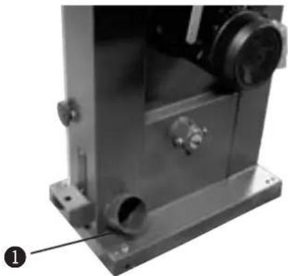
Close-up of a metallic mechanical component with mounting flanges and a labeled part (1), no visible text or symbols.Fig. 1: Connection ports
The machine has to be connected to a dust extractor. The connection values and the position of the connection port are shown on the picture.
The air speed at the connection point has to be a minimum of 20 m/s for materials with a humidity less than 12 %.
The air speed should be increased to 25-28 m/s to extract dust from more humid materials (over 12 %).
Only flame resistant vacuum hoses can be used, conforming to DIN 4102 B1 and any other safety regulations in effect.
| Vacuum connection-∅ 120 mm |
| Air speed 20 m/s |
| Min. depression 773 Pa |
| Volume flow min. 814 Cubic meters per hour. |
① Connection ports 120 mm
5. Setting up the machine
5.1 Overview
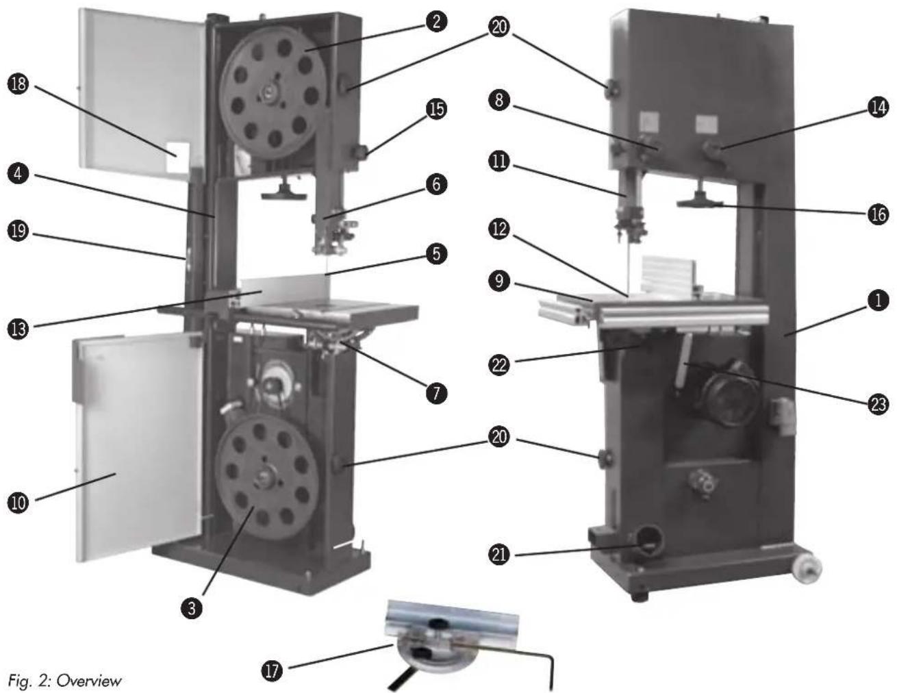
1 Machine base-frame
② Upper wheel
3 Lower wheel
4 Rising part of saw blade
⑤ Falling part of saw blade
6 Upper blade guide
7 Lower blade guide
8 Blade guide height adjustment
9 Work table
10 Wheel door
11 Height adjustable protection device
12 Table insert
13 Guide fence
14 Saw blade track - Adjuster hand wheel and clamping lever
15 Lock wheel - Blade guide height adjustment
16 Blade tension hand wheel
⑰ Mitre fence (Accessories)
18 Saw blade tension indicator window
19 On/Off switch
20 Lock wheel - Wheel door
21 Vacuum connector
22 Table tilt - clamping lever
23 Table tilt
5.2 Data plate

Fig. 3: Data plate
The data plate displays the following specifications:
- Manufacturer info
- Model designation
- Machine number
- Voltage
- Phases
- Frequency
- Capacity
- Electricity
• Year of construction
• Particulars for the motor
6 Setup and installation
6.1 Safety instructions

Warning! Risk of injury: Improper assembly and installation can lead to serious bodily injury or equipment damage. For this reason these works may only be carried out by authorised, trained personnel who are familiar with the operation of the machine and in strict observance of all safety instructions.
- Ensure that there is sufficient space for working around the machine. Ensure there is ample distance between the machine and other solid contructions such as a wall or other machines.
- Keep the work area orderly and clean. Components
and tools that are not fixed or have been left lying around may be the cause of accidents!
- Install the safety equipment according to the instructions and check that it functions properly.

Warning! Danger – electric current: Work on electrical fittings may only be carried out by qualified personnel and in strict observance of the safety instructions.
Before assembling and installing the machine, check to make sure it is complete and in good condition.

Warning! Risk of injury: An incomplete, faulty or damaged machine can lead to serious bodily injury or equipment damage. Assemble and install the machine and other units only if they are complete.

Attention! Risk of material damage: Only operate the machine in ambient temperatures from +10° to +40°C. If the instructions are not followed, damage may occur during storage.
6.2 Positioning
Characteristics of the installation site:
• Operation/room temperature: +10° to +40°C.
- Ensure that the work surface is sufficiently stable and has the proper load-bearing capacity.
- Provide sufficient light at the workstation.
- Ensure there is sufficient clearance to or shield neighbouring workstations.
- Risk of injury! Keep machines, tools and accessories etc. out of the reach of children.
- Vacuum hoses and electrical wires should be layed in such a way as to avoid tripping over them.
6.2.1 Safety instructions
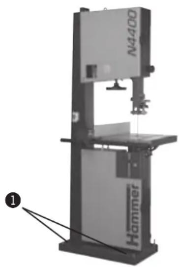
natural_image
Industrial machine labeled 'N4400' with a hammer mechanism, shown without any readable text or symbols beyond the label.Fig. 4: Screws
The following points are important for a correct and efficient machine installation:
- The machine should be bolted to the floor with M10 screws for optimum stability, however take care not to overtighten the fastening bolts as this will increase vibrations. It is advisable to place vibration dampening pads between the floor and the machine.
• Install the machine in such a way as not to amplify the vibrations and machine noise. - Ensure that workplace lighting is adequate.
- If the machine is to be installed between other machines, leave at least 80 cm distance in order to avoid collisions when cutting large work-pieces and to allow the use of equipment such as roll supports and additional tables.
1 Screws
6.2.2 Setting up the work table
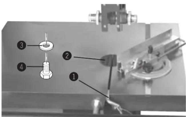
Fig. 5: Work table
- The table insert and positioning pin have to be removed to set up the work table.
- Thread the work table around the saw blade and mount to the machine using SKT screws and washers.
- Re-affix the table insert and positioning pin.
① Positioning pin
② Table insert
③ Washers
4 Screw
7 Operation
7.1 Safety instructions

Warning: Risk of injury: Improper operation may lead to severe bodily injury or material damage. For this reason these works may only be carried out by authorised, trained personnel who are familiar with the operation of the machine and in strict observance of all safety instructions.
Before starting work:
- Before assembling and installing the machine, check to make sure it is complete and in good condition.
- Ensure that there is sufficient space for working around the machine.
- Keep the work area orderly and clean. Components and tools that are not fixed or have been left lying around may be the cause of accidents!
- Ensure that all safety devices have been properly installed.
- Adjustments to the machine or tool replacement may only be conducted once the machine has stopped.
- Only clamp authorised tools to the machine.
- Install the vacuum system according to the instructions and test its function.
- Only process workpieces that can be safely placed on the machine and guided.
- Carefully inspect workpieces for foreign matter (nails, screws) which might impair processing.
- Support long work-pieces with additional surface equipment (e.g. Table extensions, Roll supports).
- Ensure that each unit is rotating in the proper direction.
- Keep tools for handling short and narrow workpieces close at hand.
- Before switching on the machine, always check to make sure that there are no other persons in the immediate vicinity of the machine.
During operation:
- When changing to another workpiece or when there is a malfunction, first switch off the machine and then secure it against being switched on again accidentally.
- Do not switch off, circumvent or decommission protective and safety devices during operation.
- Do not overload the machine! It is safer and performs better if operated within its power range.
When working on or with the machine, the following must be strictly observed:
- Persons with long hair who are not wearing a hairnet are not permitted to work on or with the machine.
- It is prohibited to wear gloves while working on or with the machine.
All jewellery (rings, bracelets, necklaces, etc.) must be removed before starting work on or with the machine.
When working on or with the machine, the following must always be worn by personnel:
- Sturdy, tight-fitting clothing (tear-resistant, no wide sleeves).
- Protective footwear that protects the feet from heavy falling objects and prevents sliding on slippery floors.
• Ear protection to protect against loss of hearing.

Attention: Risk of material damage: Only operate the machine in ambient temperatures from +10° to +40°C. If the instructions are not followed, damage may occur during storage.
Warning: Danger – electric current: Work on electrical fittings may only be carried out by qualified personnel and in strict observance of the safety instructions.
7.2 Switching on the machine

Warning: Risk of injury due to insufficient preparation!
It is only permitted to switch on the machine if, for the work at hand, the required preconditions are fulfilled and any preliminary work is completed. For this reason the instructions for adjusting, fitting and operating (see the corresponding chapters) must be read before switching on the machine.
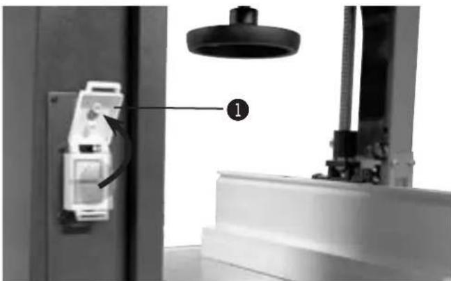
natural_image
Close-up of a mechanical testing setup with a device labeled '1' and a ceiling fixture (no readable text or symbols)Fig. 6: On- and Off switch
The bandsaw has an On- and Off switch.
The switch has to be opened to be able to switch on the device.
1 Lid
7.3 Authorised work techniques
If the switch lid is closed, then the machine is switched off automatically.
7.4 Authorised work techniques
7.4.1 Positioning the 90° end stop on the work table
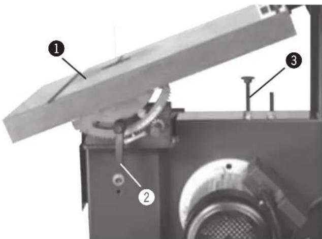
Fig. 7: End stop
- Disconnect the machine from the mains supply.
- Loosen clamping lever.
- Tilt the work table until it rests on the stop screw.
• Determine the exact angle using a 90° triangle. - If the 90^ in the initial position is not correct, adjust the stop screw accordingly.
- Check the 90° angle once the clamping lever is back in place.
① Work table
② Secure the clamping lever
③ Stop screw
7.4.2 Parallel cutting fence
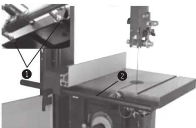
Fig. 8: Parallel cutting fence
- Use a nut to mount the fence rail to the machine table.
- Slide the premounted fence onto the track.
① Nut
② Fence rail
7.4.3 Saw blade replacement/tension
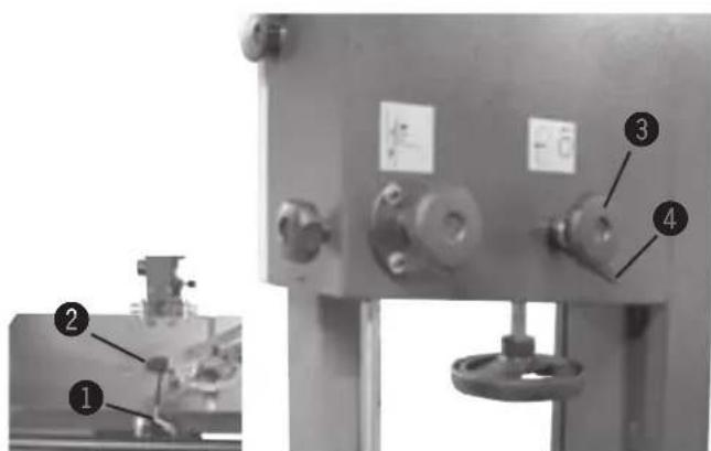
Fig. 9: Saw blade replacement
- Disconnect the machine from the mains supply.
- Remove table insert and positioning pin.
- Open wheel door.
- Unthread old blade through the machine table.
- Place new saw blade over both wheels (note the direction of the cut!).
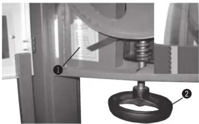
- Release the clamping lever and using the hand wheel, set the saw blade track so that it lies in the centre of both wheels (thereby turning the wheels!) Close the clamping lever.
natural_image
Mechanical assembly diagram showing a spring-loaded component with labeled parts (1 and 2), no readable text or symbols present.Fig. 10: Scale
1 Positioning pin
② Table insert
③ Hand wheel
4 Clamping lever
- Check the saw blade tension and if required, adjust with the hand wheel. The values refer to the saw blade width.
1 Scale
② Hand wheel
7.4.4 Longitudinal cut along the marked line
natural_image
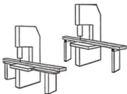
Technical line drawing of two mechanical assembly components (no text or symbols)Fig. 11: Longitudinal cut
All uses which differ from the following work techniques have not been intended for this machine and are therefore not authorised.
Feed the work-piece with constant speed and pressure forwards without applying sideways pressure. Do not interrupt the cut and do not pull the work-piece backwards. When cutting large pieces, use appropriate table extensions or roll supports.
7.4.5 Cutting round work-pieces in the transverse direction
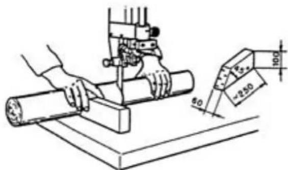
Use an appropriate device with the minimum measurements as depicted in Fig. 12 to avoid the work-piece twisting during the cutting process.
Fig. 12: Cutting a circular work-piece
7.4.6 Longitudinal cut of narrow or thin work-pieces with the guide fence
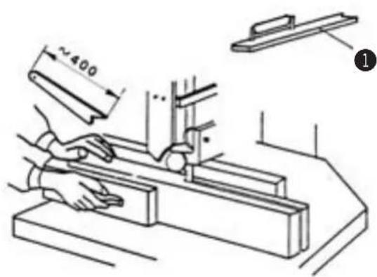
Use a push stick as depicted in Fig. 13 to prevent your hands from coming too close to the saw blade.
① Push stick
7.4.7 Cutting work-pieces on the upright edge
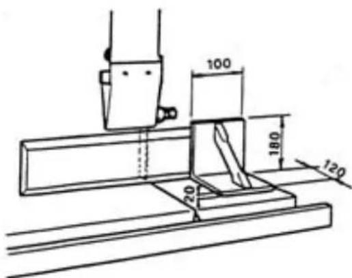
Use an auxiliary fence with the minimum measurements to guide the work-piece safely.
Fig. 14: Auxiliary fence
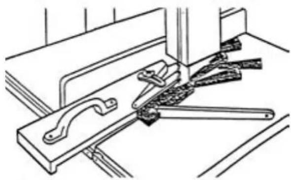
7.4.8 Angular cuts
natural_image
Technical line drawing of a mechanical clamp or bracket assembly (no text or symbols)Fig. 15: Angular cuts
Use auxiliary equipment as depicted in the figure.
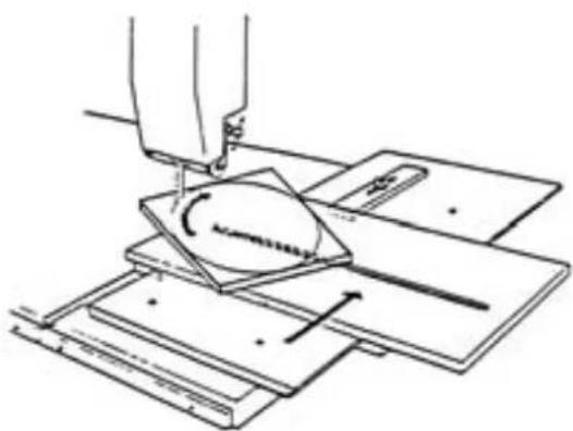
7.4.9 Circular cuts
natural_image
Diagram of a sewing machine needle stitching fabric layers (no text or symbols)Fig. 16: Circular cuts
Use auxiliary equipment as depicted in the figure.
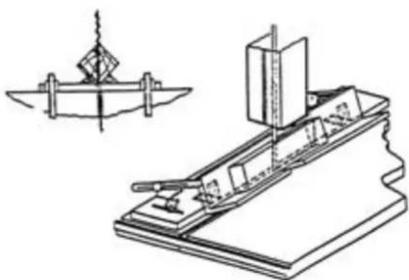
7.4.10 Diagonal cross cuts of rectangular work-pieces
natural_image
Technical line drawing of a mechanical device with a separate schematic diagram (no text or symbols)Fig. 17: Cross cut
Use auxiliary equipment as depicted in the figure.
7.5 Applications
7.5.1 Blade selection and maintenance
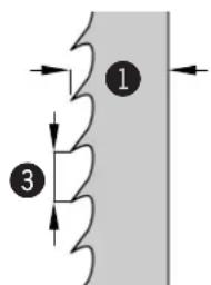
Selecting the type of saw blade and its width, depends on the material to be cut and the type of cut:
- Narrow saw blades are designed for curved and circular cuts, whereas wide saw blades are designed for straight cuts.
- A fine-toothed saw blade is required for hard wood, whereas a coarse-toothed saw blade is required for soft wood.
The gap between the individual teeth should be large enough to carry the material chips and to throw them away. If the gap is too small, the blade will overheat and rupture.
Do not use kinked, ruptured or bent saw blades.
radar
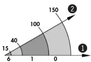
| Category | Value | | -------- | ----- | | 1 | 15 | | 2 | 150 | | 3 | 40 |Fig. 18: Saw blades
For soft wood, the set should be a max. of twice the thickness of the saw blade and for hard wood, a max. of 1.5 times the thickness of the saw blade.
Change blunt blades and have them sharpened by a specialist workshop or purchase a new saw blade.
It is recommended to use only high quality saw blades.
The following saw blades may be used:
Art. No. Blade width Tooth spacing
| 13.7.3406 | 6 mm | 4 mm |
| 13.7.3410 | 10 mm | 6 mm |
| 13.7.3415 | 16 mm | 8 mm |
| 13.7.3420 | 19 mm | 8 mm |
① Blade width
2 Radius cut
③ Tooth spacing
7.5.2 Adjusting the saw blade guide
7.5.2.1 Upper blade guide
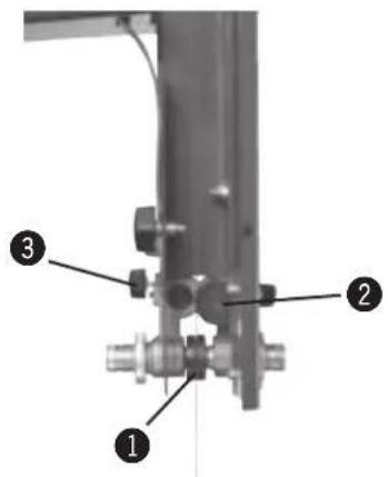
Fig. 19: Guide rollers
Do not change settings whilst the machine is in operation!
The upper saw blade guide has to be lowered as closely as possible to the work-piece (5-10 mm). To set the height, open the clamping screw and turn the hand wheel until the desired height has been reached. Tighten the clamping screw once again.
① Guide rollers
② Support roller
③ Clamping screw
7.5.2.2 Lower blade guide
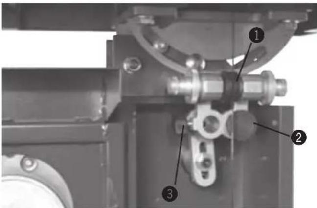
Fig. 20: Saw blade guide
The side guide rollers should touch the saw blade slightly so as to obtain a straight and vibration-free cut.
The rear support roller prevents the saw blade thrusting backwards whilst cutting.
To adjust the position of the rollers, simply loosen the clamping screw.
① Guide rollers
② Support roller
③ Clamping screw
8. Maintenance
8.1 Safety instructions

Warning! Risk of injury: Improper adjustment and setup work can lead to serious bodily injury or material damage. For this reason these works may only be carried out by authorised, trained personnel who are familiar with the operation of the machine and in strict observance of all safety instructions.
- Before beginning any maintenance work on the machine, switch off the machine and secure it against accidentally being turned on again.
-
Before commencing any work with the machine, inspect it to ensure that it is complete and in technically good condition.
-
Ensure that there is sufficient space for working around the machine.
- Keep the work area orderly and clean. Components and tools that are not fixed or have been left lying around may be the cause of accidents!
- Install the safety equipment according to the instructions and check that it functions properly.
Warning! Danger – electric current: Work on electrical fittings may only be carried out by qualified personnel and in strict observance of the safety instructions.
8.2 Cleaning and lubrication
- Regularly remove accumulated saw dust with a vacuum cleaner from the inside of the machine.
- Remove accumulated resin and dust from bearing surfaces taking care not to damage the wheel operating surfaces.
- The wheel bearings are sealed and do not require lubricating.
It is not necessary to lubricate other machine parts as the circulating saw dust will get caught on every greased or
oiled surface and this would for example hinder the gliding properties of the blade guide or the belt tension unit.
Check periodically that all screws are tight and also check the condition of the protective equipment.
8.3 Drive belts
Check periodically that all screws are tight and also check the condition of the protective equipment.
The drive belt tension must be rechecked after a few hours of use to correct slackening. To check the tension, press the belt inwards in the centre, using a load up to
3-4 kg. The belt deflection should not exceed 5-6 mm.
8.3.1 Adjusting the belt tension
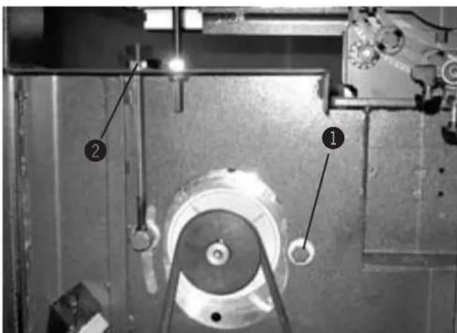
Fig. 21: Drive belts
- Loosen nut.
- The tension of the belt can be adjusted by tightening or loosening the nut.
- Screw nut on again.
It is important that the belts are always correctly tensioned, as belts which are too loose will weaken the drive power and the impact of the brakes. Belts which are too tight will lead to overheating.
① Nut 1
② Nut 2
9 Faults
9.1 Safety instructions

Warning! Risk of injury: Removing faults incorrectly can result in personal injury or damage the machine. For this reason these works may only be carried out by authorised, trained personnel who are familiar with the operation of the machine and in strict observance of all safety instructions.
Warning! Danger – electric current: Work on electrical fittings may only be carried out by qualified personnel and in strict observance of the safety instructions.
9.2 What to do in case of a fault
Strickly speaking:
- In the event of a breakdown which creates danger for either personell or equipment the machine should be stopped immediately using the emergency stop.
- Also disconnect machine from the mains and secure it from being started up.
• Inform those responsible of faults immediately.
- Type and extent of fault should be determined by an authorised professional, as well as the cause and repair.
9.3 What to do after rectifying the fault

Warning! Risk of injury!
Before switching the machine back on:
- The fault and its cause are professionally repaired.
- All safety measures have been installed according to regulations and are faultless.
- People are not located in the danger area of the machine.
9.4 Faults, causes and repairs
| Problem Possible cause Repair | ||
| The motor will not start Safety break switches are breaking the electric circuit | Ensure that the side doors are closed properly | |
| Ensure that the Emergency Off Switch (if present) is unlocked | ||
| The On-switch on the motor safety switch will not engage | Check that the air brake switch is in the correct position, or if a Y-switch is present, check that it is set to „0“ | |
| One of the emergency-stop buttons is pressed down. | Contact an electrician | |
| The machine is not performing | Incorrect motor connection | Contact an electrician |
| Loose drive belts | Tension according to these instructions | |
| The cuts are not straight | Check sharpness and set of saw bladeCheck the guide fence alignment | |
| The saw blade is torn at the base of the individual teeth | Incorrect sharpness and constant overheating, or otherwise incorrect set of saw blade | |
| Width of saw blade is too thick in relation to the diameter of the wheel | ||
| Incorrectly aligned wheels | ||
| Defect or soiled wheel running surfaces | Contact a qualified technician | |
| The saw blade is rupturing on the rear side | Feed rate or pressure is too high during cutting | |
| Poor welded joint | Remove present welded joint or redo welded joint | |
| The rear support roller of the saw blade guide is defective | ||
| The saw blade is slipping to the back at the beginning of the cut | The saw blade is not sharp enough or is unsuitable for the type of material to be cut, or the surface of the wheel is defective | |
| The blade is too thick in relation to the diameter of the wheel | ||
| Incorrect blade tension | ||
Faults
| Problem Possible cause Repair | ||
| The saw blade is slipping to the back at the beginning of the cut | Incorrect blade guide settings, poor machinability of the material to be cut or due to not releasing the blade tension when machine is idle will cause the saw blade to be overloaded | |
| Can occur due to unauthorised adjustment of the lower wheel's adjuster screw | The wheels are not aligned with one another | |
| Irregularities on the wheel's running surface e.g. accumulated dust resulting from cutting resinous materials | ||
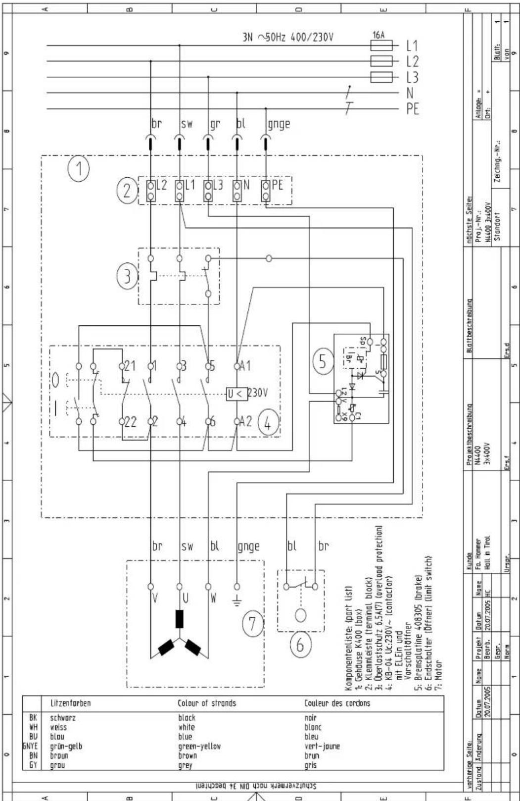
10 Circuit diagram
10.1 Safety instructions
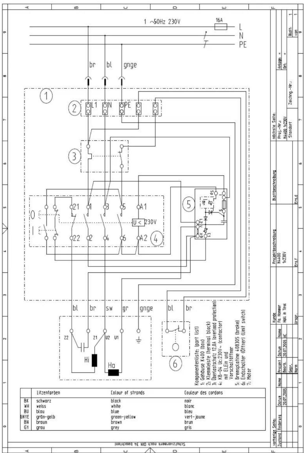
Fig. 22: Circuit diagram 1x 230 V
other
| Component | Label | |-----------|-------| | Black | BN | | White | BH | | Blue | blu | | Green-yellow | brown | | Grey | grey | | Brown | brown | | Blue | blue | | Green-yellow | yellow | | Grey | grey | | Brown | brown | | Blue | blue | | Green-yellow | yellow | | Grey | grey | | Brown | brown | | Blue | blue | | Green-yellow | yellow | | Grey | grey | | Brown | brown | | Blue | blue | | Green-yellow | yellow | | Grey | grey | | Brown | brown | | Blue | blue | | Green-yellow | yellow | | Grey | grey | | Brown | brown | | Blue | blue |11 Spare parts
11.1 Machine base-frame
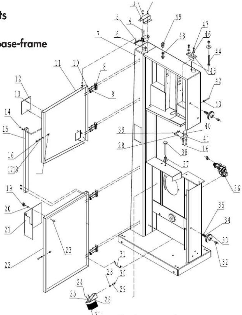
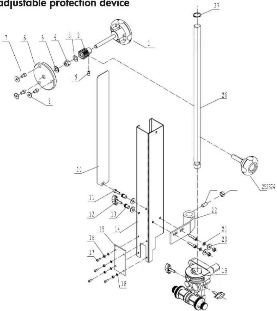
11.3 Height adjustable protection device
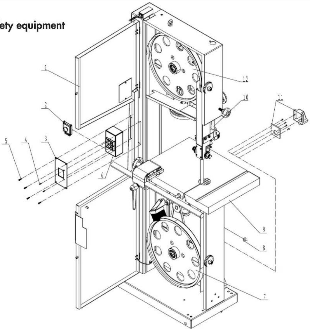
11.6 Safety equipment
Adjusting the belt tension, 28
Angular cuts, 24
Applications, 25
C
Causes and problem elimination, 30
Changes, 8
Circuit diagram, 32
Circuit diagram 1 x 230V, 32
Circuit diagram 3 x 400V, 33
Circular cuts, 24
Cleaning, 27
Conversions, 8
Copyright, 6
Cross cut, 24
Cutting circular work-pieces, 23
Cutting work-pieces on the upright edge, 23
D
Dangers, 10
Data plate, 16
Declaration of Conformity, 11
Dimensions, 12
Disposal, 7
Drive belts, 28
Dust extraction, 14
E
Electrical connection, 12
Explanations of the symbols, 5
F
Faults, 29
G
General, 5
|
Installation, 17
Installation dimensions, 18
L
Liability, 6
Longitudinal cut along a line, 22
Longitudinal cut of narrow or thin work-pieces, 23
Lower blade guide, 26
Lubrication, 27
M
Maintenance, 27
N
Noise emissions, 13
0
Operation, 19
Other risks, 10
Overview, 15
P
Parallel cutting fence, 21
Personal protective equipment, 10
Positioning, 17
S
Safety, 8
Safety instructions, 17, 19, 27, 29
Saw blade maintenance, 25
Saw blade replacement, 22
Saw blade selection, 25
Setting the 90° end stop, 20
Setting the saw blade guides, 26
Setting up the machine, 15
Setting up the work table, 28
Spare parts, 6
Storage conditions, 12
Switching off the machine, 20
Switching on the machine, 20
T
Technical data, 12
Tension saw blade, 22
U
Upper blade guide, 26
W
Warranty, 6
Warranty notice, 6
Weight, 12
What is required of the personnel, 9
What to do after rectifying the fault, 29
What to do in case of a fault, 29
Working techniques, 20
Work safety, 9
Hammer
KR-Felder-Str. 1
A-6060 Hall in Tirol
Tel.: +43 (0) 52 23 / 45 0 90
Fax: +43 (0) 52 23 / 45 0 99
Email: info@hammer.at
| Order No. Article Description Pcs. | ||

□ YES, send me the new HAMMER-catalog.
First Name Name/Company Name
Street + House-No.
Phone No. (Area Code)
Mobile No. (Code)
□ Yes, please send me your Newsletter.
| Email Address | ||||||||||||||||||||||||||||||||||||||||||||||||||||||||||||||||||||||||||||||||||||||||||||||||||||
Send to my address, subject to your delivery and payment conditions:
Date: Signature:
Please stamp
Hammer
WARRANTY
In this position is your Warranty Card!
After sending in your warranty card you will receive:
A certificate of the expanded HAMMER warranty!
HAMMER-Info-Zentrum
Tel.: (A) 0 52 23 / 45 0 90
Fax: (A) 0 52 23 / 45 0 99
Email: info@hammer.at
http://www.hammer.at
Business hours:
Mo.-Fr.: 09 ^00 -12 ^00
13^ - 17^
Sa.: 09 ^00 - 11 ^30
Hammer-Info-Zentrum
KR-FELDER-STR. 1
A-6060 HALL in Tirol Austria
| First Name Name/Company Name |
| Important: For company orders - please provide the VAT registration number! |
| Street + House-No. Post Code/City |
| Phone No. (Area Code) Fax No. (Area Code) |
| Mobile No. (Code) Availability (time) |
□ Yes, please send me your Newsletter.
| Email Address | ||||||||||||||||||||||||||||||||||||||||||||||||||||||||||||||||||||||||||||||||||||||||||||||||||||
Please fill in the following information from your data plate on your machine:
| Machine type: | Machine Number: |
| Electrical Equipment: V PH Hz A | KW Year of Manufacture |
| Received on: Machine was | bought from: |
Machine Location:
□ Cellar / basement First or ground floor Loft / Attic

Machine setup and training was completed by: □ HAMMER- Qualified personnel □ HAMMER- Operation manual

YES,
send me the new
HAMMER-catalog.
- HAMMER | A product of the FELDER GROUP
- Safety 8
- Declaration of Conformity 11
- Technical data 12
- Setting up the machine 15
- Setup and installation 17
- Operation 19
- Table of Contents
- Maintenance 27
- Faults 29
- Circuit diagram 32
- Spare parts 34
- Index 40
- General
- Explanations of the symbols
- Warning: Risk of injury or death!
- Warning: Danger – electric current!
- Attention: Risk of material damage!
- Attention:
- Information regarding the manual
- Liability and warranty
- Copyright
- Warranty notice
- Spare parts
- Disposal
- Safety
- Intended use
- Manual contents
- Making changes and modifications to the machine
- Responsibilities of the operator
- What is required of the personnel
- Work safety
- Personal safety
- Hazards arising from the machine
- Other risks
- Declaration of Conformity
- Technical data
- Dimensions and weight
- Operation and storage conditions
- Electrical connection
- Technical data
- Noise emissions
- Dust extraction
- Setting up the machine
- Overview
- Data plate
- Setup and installation
- Safety instructions
- Positioning
- Characteristics of the installation site:
- Safety instructions
- Setting up the work table
- Operation
- Safety instructions
- Before starting work:
- During operation:
- When working on or with the machine, the following must be strictly observed:
- When working on or with the machine, the following must always be worn by personnel:
- Switching on the machine
- Authorised work techniques
- Authorised work techniques
- Positioning the 90° end stop on the work table
- Parallel cutting fence
- Saw blade replacement/tension
- Longitudinal cut along the marked line
- Cutting round work-pieces in the transverse direction
- Longitudinal cut of narrow or thin work-pieces with the guide fence
- Cutting work-pieces on the upright edge
- Angular cuts
- Circular cuts
- Diagonal cross cuts of rectangular work-pieces
- Applications
- Blade selection and maintenance
- Adjusting the saw blade guide
- Upper blade guide
- Lower blade guide
- Maintenance
- Safety instructions
- Cleaning and lubrication
- Drive belts
- Adjusting the belt tension
- Faults
- Safety instructions
- What to do in case of a fault
- Strickly speaking:
- What to do after rectifying the fault
- Before switching the machine back on:
- Faults, causes and repairs
- Faults
- Circuit diagram
- Safety instructions
- Spare parts
- Machine base-frame
- C
- D
- E
- F
- G
- |
- L
- M
- N
- 0
- P
- S
- T
- U
- W
- Hammer
- WARRANTY
Brand : Hammer
Model : N4400
Category : Saw