
VP17 - Coffee maker Bunn - Free user manual and instructions
Find the device manual for free VP17 Bunn in PDF.


| Product Type | Commercial Coffee Brewer |
| Brand | Bunn |
| Model | VP17 |
| Power Requirements (Standard) | 120 V AC, 15 A, 60 Hz |
| Power Requirements (B Model) | 100 V AC, 20 A, 50 Hz |
| Batch Size | Half gallon (approx. 1.9 L) |
| Warming Plates | Up to 3 warming stations (model dependent) |
| Brewing Method | Pour-over with sprayhead |
| Water Tank Capacity | Fills to capacity during initial setup; uses three pitchers of water |
| Sprayhead | Six-hole stainless steel sprayhead |
| Filter Type | Bunn paper filters (required for proper extraction) |
| Control Thermostat | Adjustable, located in trunk |
| Safety Features | Limit thermostat, grounded chassis, warnings for hot surfaces |
| Material | Stainless steel tank, plastic housing |
| Warranty | 1 year parts and labor; 3 years on electronic boards; 2 years on compressors; 3 years on grinding burrs |
| Cleaning Instructions | Use damp cloth with mild non-abrasive detergent; clean sprayhead holes; use deliming spring in hard water areas |
| Deliming | Regularly inspect and delime tank to prevent mineral buildup |
| Electrical Connection | 2-wire grounded service; disconnect power before servicing |
| Intended Use | Indoor use on sturdy counter or shelf |
| Service Access | Top cover, front panel, and warmer assemblies removable |
| Spare Parts | Available via Bunn-O-Matic (parts catalog at www.bunn.com) |
Frequently Asked Questions - VP17 Bunn
User questions about VP17 Bunn
0 question about this device. Answer the ones you know or ask your own.
Ask a new question about this device
Download the instructions for your Coffee maker in PDF format for free! Find your manual VP17 - Bunn and take your electronic device back in hand. On this page are published all the documents necessary for the use of your device. VP17 by Bunn.
USER MANUAL VP17 Bunn
DISCONTINUED VERSION The information in this manual is no longer current.
natural_image
Technical line drawing of a kitchen appliance with two circular cutouts on a base (no text or symbols)OPERATING & SERVICE MANUAL
BUNN-O-MATIC CORPORATION
POST OFFICE BOX 3227 SPRINGFIELD, ILLINOIS 62708-3227
PHONE: (217) 529-6601 FAX: (217) 529-6644
To obtain the Illustrated Parts Catalog, visit the Bunn-O-Matic website, at www.bunn.com. This is absolutely FREE, and the quickest way to obtain the catalog. Contact Bunn-O-Matic Corporation at 1-800-286-6070 to obtain a paper copy of the required Illustrated Parts Catalog mailed via U.S. Postal Service.
INTRODUCTION
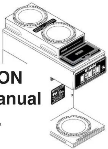
This equipment will brew a half-gallon batch of coffee into an awaiting dispenser. It is only for indoor use on a sturdy counter or shelf.
WARRANTY
Bunn-O-Matic Corp. (“Bunn”) warrants the equipment manufactured by it to be commercially free from defects in material and workmanship existing at the time of manufacture and appearing within one year from the date of installation. In addition:
1.) Bunn warrants electronic circuit and/or control boards to be commercially free from defects in material and workmanship for three years from the date of installation.
2.) Bunn warrants the compressor on refrigeration equipment to be commercially free from defects in material and workmanship for two years from the date of installation.
3.) Bunn warrants that the grinding burrs on coffee grinding equipment will grind coffee to meet original factory screen sieve analysis for three years from date of installation or for 30,000 pounds of coffee, whichever comes first.
This warranty does not apply to any equipment, component or part that was not manufactured by Bunn or that, in Bunn's judgement, has been affected by misuse, neglect, alteration, improper installation or operation, improper maintenance or repair, damage or casualty.
THE FOREGOING WARRANTY IS EXCLUSIVE AND IS IN LIEU OF ANY OTHER WARRANTY, WRITTEN OR ORAL, EXPRESS OR IMPLIED, INCLUDING, BUT NOT LIMITED TO, ANY IMPLIED WARRANTY OF EITHER MERCHANTABILITY OR FITNESS FOR A PARTICULAR PURPOSE. The agents, dealers or employees of Bunn are not authorized to make modifications to this warranty or to make additional warranties that are binding on Bunn. Accordingly, statements by such individuals, whether oral or written, do not constitute warranties and should not be relied upon.
The Buyer shall give Bunn prompt notice of any claim to be made under this warranty by telephone at (217) 529-6601 or by writing to Post Office Box 3227, Springfield, Illinois, 62708-3227. If requested by Bunn, the Buyer shall ship the defective equipment prepaid to an authorized Bunn service location. If Bunn determines, in its sole discretion, that the equipment does not conform to the warranty, Bunn shall repair the equipment with no charge for parts during the warranty period and no charge for labor by a Bunn Authorized Service Representative during the warranty period. If Bunn determines that repair is not feasible, Bunn shall, at its sole option, replace the equipment or refund the purchase price for the equipment.
THE BUYER'S REMEDY AGAINST BUNN FOR THE BREACH OF ANY OBLIGATION ARISING OUT OF THE SALE OF THIS EQUIPMENT, WHETHER DERIVED FROM WARRANTY OR OTHERWISE, SHALL BE LIMITED, AS SPECIFIED HEREIN, TO REPAIR OR, AT BUNN'S SOLE OPTION, REPLACEMENT OR REFUND.
In no event shall Bunn be liable for any other damage or loss, including, but not limited to, lost profits, lost sales, loss of use of equipment, claims of Buyer's customers, cost of capital, cost of down time, cost of substitute equipment, facilities or services, or any other special, incidental or consequential damages.
USER NOTICES
Carefully read and follow all notices in this manual and on the equipment. All labels on the equipment should be kept in good condition. Replace any unreadable or damaged labels.
12364.0000
00833.0000

CAUTION
WARMERS AND SURFACES ARE HOT
POUR IN WATER ONLY
USER NOTICES (cont.)

WARNING
◆ Fill water tank before turning - on - thermostat or connecting appliance to power source.
◆ Use only on a properly protected circuit capable of the rated load.
◆ Electrically ground the chassis.
◆ Follow national/local electrical codes.
◆ Do not use near combustibles.
FAILURE TO COMPLY RISKS EQUIPMENT DAMAGE, FIRE, OR SHOCK HAZARD
READ THE ENTIRE OPERATING MANUAL BEFORE BUYING OR USING THIS PRODUCT
THIS APPLIANCE IS HEATED WHENEVER CONNECTED TO A POWER SOURCE 00831.0000F 3/08 ©1988 BUNN-O-MATIC CORPORATION
# 00831.0000

00658.0000

CAUTION
WARMERS AND SURFACES ARE HOT
POUR IN WATER ONLY
02763.0000

WARNING
To reduce the risk of electric shock, do not remove or open cover. No user-serviceable parts inside. Authorized service personnel only. Disconnect power before servicing.
37881.0000

WARNING
To reduce the risk of electric shock, do not remove or open cover. No user-serviceable parts inside.
Authorized service personnel only. Disconnect power before servicing.
37881.0002
ELECTRICAL REQUIREMENTS
CAUTION - The brewer must be disconnected from the power source until specified in Initial Set-Up.
The brewer has an attached cordset and requires 2-wire grounded service rated 120 volts ac, 15 amp, single phase, 60 Hz.
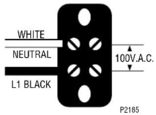
"B" models require 2-wire, grounded service rated 100 volts ac, 20 amp, single phase, 50 Hz. Proceed as follows:
Electrical Hook-Up (Model "B" Only)
CAUTION – Improper electrical installation will damage electronic components.
- An electrician must provide electrical service as specified.
- Using a voltmeter, check the voltage and color coding of each conductor at the electrical source.
- Place the heater switch, located on the left front of the control panel on "B" Models, in the "OFF" (lower) position.
- Remove the front panel beneath the sprayhead.
- Feed the cord through the strain relief and connect it to the terminal block.
- Connect the brewer to the power source and verify the voltage at the terminal block before proceeding. Replace the front panel.
INITIAL SET-UP
CAUTION - The brewer must be disconnected from the power source throughout the initial set-up, except when specified in the instructions.
- Insert an empty funnel into the funnel rails.
- Place an empty decanter under the funnel.
- On "B" Models, place the heater switch of the brewer in the "OFF" (lower) position and connect the brewer to the power source.
- Pour three pitchers of tap water into the screened area on top of the brewer. Allow approximately two minutes between pitchers for water to flow into the tank. While the third pitcher of water is entering the tank, the tank will fill to capacity and the excess will flow from the sprayhead, out of the funnel, and into the dispenser.
- When the flow of water from the funnel stops, place the heater switch of the brewer in the "ON" (upper) position and wait approximately twenty minutes for the water in the tank to heat to the proper temperature. Some water will drip from the funnel during this time; this is due to expansion and should not occur thereafter.
- Pour one pitcher of tap water into the screened area on top of the brewer.
- After water has stopped flowing from the funnel, allow the water in the tank to reheat to the proper temperature.
- Empty the decanter. The brewer is now ready for use in accordance with the coffee brewing instructions.
COFFEE BREWING
- Insert a BUNN ^® filter into the funnel.
- Pour the fresh coffee into the filter and level the bed of grounds by gently shaking.
- Slide the funnel into the funnel rails.
- Place an empty dispenser beneath the funnel.
- Pour one pitcher of tap water into the screened area on top of the brewer.
- When brewing is completed, simply discard the grounds and filter.
CLEANING
-
The use of a damp cloth rinsed in any mild, non-abrasive, liquid detergent is recommended for cleaning all surfaces on Bunn-O-Matic equipment.
-
Check and clean the sprayhead. The sprayhead holes must always remain open.
-
With the sprayhead removed, insert the deliming spring (provided) all the way into the sprayhead tube. When inserted properly, no more than two inches of spring should be visible. Saw back and forth five or six times.
NOTE – In hard water areas, this may need to be done daily. It will help prevent liming problems in the brewer and takes less than a minute.
TROUBLESHOOTING
A troubleshooting guide is provided to suggest probable causes and remedies for the most likely problems encountered. If the problem remains after exhausting the troubleshooting steps, contact the Bunn-O-Matic Technical Service Department.
- Inspection, testing, and repair of electrical equipment should be performed only by qualified service personnel.
- All electronic components have 120 volt ac and low voltage dc potential on their terminals. Shorting of terminals or the application of external voltages may result in board failure.
- Intermittent operation of electronic circuit boards is unlikely. Board failure will normally be permanent. If an intermittent condition is encountered, the cause will likely be a switch contact or a loose connection at a terminal or crimp.
- Solenoid removal requires interrupting the water supply to the valve. Damage may result if solenoids are energized for more than ten minutes without a supply of water.
- The use of two wrenches is recommended whenever plumbing fittings are tightened or loosened. This will help to avoid twists and kinks in the tubing.
• Make certain that all plumbing connections are sealed and electrical connections tight and isolated.
• This brewer is heated at all times. Keep away from combustibles.
WARNING - • Exercise extreme caution when servicing electrical equipment.
• Unplug the brewer when servicing, except when electrical tests are specified.
• Follow recommended service procedures
- Replace all protective shields or safety notices
| PROBLEM | PROBABLE CAUSE | REMEDY |
| Brew cycle will not start | 1. No water | Check fill basin for obstructions. |
| 2. No power or incorrect voltage to the brewer | (A1) Be sure the brewer is connected to the power source.(A2) Check the terminal block for 100 volts on "B Series" brewers across the white and black terminals. | |
| Water is not hot | (B) Check circuit breakers or fuses. | |
| 1. Tank Heater Switch (VP17B and Early Model VP17) | Refer to Service - Tank Heater Switch for testing procedures.See page 14 | |
| 2. Limit ThermostatCAUTION- Do not eliminate or bypass limit thermostat. Use only replacement part #29329.1000 | Refer to Service - Limit Thermostat for testing procedures. See page 11 | |
| 3. Control Thermostat | Refer to Service - Control Thermostat for testing procedures.See page 10 | |
| Water is not hot (cont.) | 4. Tank Heater | Refer to Service - Tank Heater for testing procedures. See page 13 |
| Inconsistent beverage level in dispenser | 1. Syphon System | The brewer must be level or slightly lower in front to syphon properly. |
| 2. Lime Build-upCAUTION - Tank and tank components should be delimed regularly depending on local water conditions. Excessive mineral build-up on stainless steel surfaces can initiate corrosive reactions resulting in serious leaks. | Inspect the tank assembly for excessive lime deposits. Delime as required. | |
| Spitting or excessive steaming | 1. Lime Build-upCAUTION - Tank and tank components should be delimed regularly depending on local water conditions. Excessive mineral build-up on stainless steel surfaces can initiate corrosive reactions resulting in serious leaks. | Inspect tank assembly for excessive lime deposits. Delime as required. |
| 2. Control Thermostat | Refer to Service - Control Thermostat for testing procedures. See page 10 | |
| Dripping from sprayhead | 1. Syphon System | The brewer must be level or slightly lower in front to syphon properly. |
| 2. Lime Build-upCAUTION - Tank and tank components should be delimed regularly depending on local water conditions. Excessive mineral build-up on stainless steel surfaces can initiate corrosive reactions resulting in serious leaks. | Inspect the tank assembly for excessive lime deposits. Delime as required. | |
| Beverage overflows dispenser | 1. Dispenser | The dispenser must be completely empty before starting a brew cycle. |
| Weak beverage | 1. Filter Type | BUNN^® paper filters must be used for proper extraction. |
| 2. Coffee Grind | A fine or drip grind must be used for proper extraction. | |
| 3. Sprayhead | A six-hole stainless steel spray-head must be used for proper extraction. | |
| 4. Funnel Loading | The BUNN^® paper filter must be centered in the funnel and the bed of ground leveled by gentle shaking. | |
| 5. Water Temperature | Place an empty funnel on an empty dispenser beneath the sprayhead. Initiate a brew cycle and check the water temperature immediately below the sprayhead with a thermometer. The reading should not be less than 195°F (91°C). Adjust the control thermostat to increase the water temperature. Replace if necessary. | |
| Dry coffee grounds remain in the funnel | 1. Funnel Loading | The BUNN^® paper filter must be centered in the funnel and the bed of grounds leveled by gently shaking. |
| Brewer is making unusual noises | 1. Tank Heater | Remove and clean lime off the tank heater. See page 13 |
| Cool beverage serving temperature | 1. ON/OFF Warmer Switch(s) | Refer to Service - ON/OFF Warmer Switch for testing procedures. See page 12 |
| 2. Warmer Element(s) | Refer to Service - Warmer Element for testing procedures. See page 16 |
SERVICE
This section provides procedures for testing and replacing various major components used in this brewer should service become necessary. Refer to Troubleshooting for assistance in determining the cause of any problem.
WARNING - Inspection, testing, and repair of electrical equipment should be performed only by qualified service personnel. The brewer should be unplugged when servicing, except when electrical tests are required and the test procedure specifically states to plug
in the brewer.
COMPONENT ACCESS
WARNING - Disconnect the brewer from the power source before the removal of any panel or the replacement of any component.
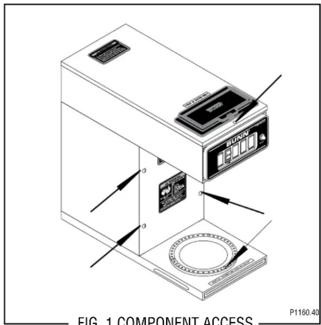
All components are accessible by the removal of the top cover and front inspection panel and warmer assemblies.
The top cover is attached with one #4-40 screw.
The front inspection panel is attached with four #6-32 screws.
The warmer assembly is attached with three #4-40 screws.
Contents
Control Thermostat....10
Limit Thermostat....11
ON/OFF Switch....12
Tank Heater....13
Tank Heater Switch 14
Warmer Elements....16
Wiring Diagrams 17
SERVICE (cont.)
CONTROL THERMOSTAT
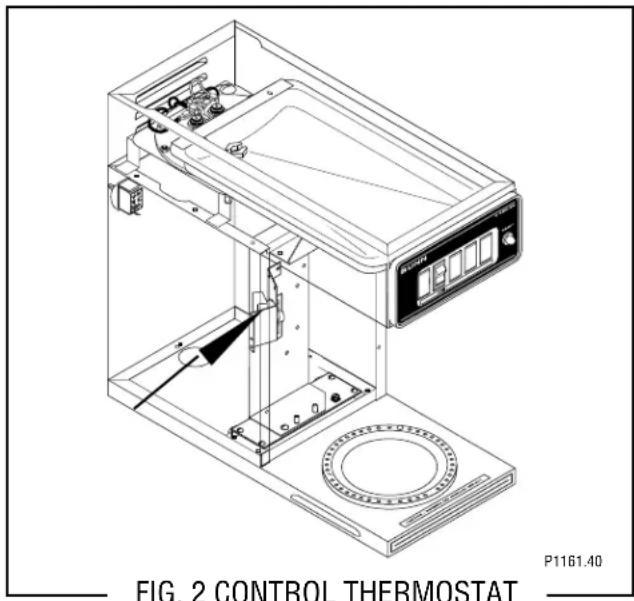
Location:
The control thermostat is located inside the trunk on the left side of the component bracket.
Test Procedures:
- Disconnect the brewer from the power source.
- With a voltmeter, check the voltage across the blue wire on the control thermostat and the white wire on the tank heater. Connect the brewer to the power source. The indication must be:
a) 100 volts ac for two wire 100 volt models.
b) 120 volts ac for two wire 120 volt models. - Disconnect the brewer from the power source.
If voltage is present as described, proceed to #4. If voltage is not present as described, refer to the Wiring Diagrams and check the brewer wiring harness.
- Gently remove the capillary bulb and grommet from the tank.
- With a voltmeter, check the voltage across the black wire of the control thermostat and the white wire on the tank heater when the control thermostat is turned "ON" (Fully clockwise). Connect the brewer to the power source. The indication must be:
a) 100 volts ac for two wire 100 volt models.
b) 120 volts ac for two wire 120 volt models. -
Voltage must not be present when the thermostat is turned to the "OFF" position.
-
Disconnect the brewer from the power source.
If voltage is present as described, reinstall the capillary tube into the tank to the line 4.5" above the bulb, the control thermostat is operating properly.
If voltage is not present as described, replace the thermostat.
Removal and Replacement:
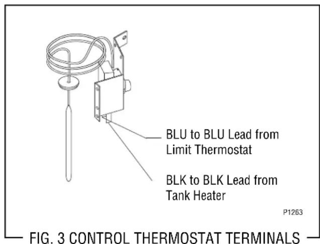
- Remove wires from control thermostat leads.
- Remove the thermostat capillary bulb by firmly pulling up on the capillary at the tank lid. This will disengage the grommet from the tank lid.
- Remove the one #8-32 screw securing the control thermostat to the component bracket in the trunk.
- Slide the grommet to the line 4.5" above the bulb on the new capillary tube.
- Insert the capillary bulb through the hole in the tank lid and press the grommet firmly and evenly so that the groove in the grommet fits into the tank lid.
- Carefully bend the capillary tube so that the tube and bulb inside the tank are in the vertical position.
NOTE - The capillary tube must be clear of any electrical termination and not kinked.
- Using one #8-32 screw secure the control thermostat to the component bracket inside the trunk.
- Refer to Fig. 3 when reconnecting the wires.
- Adjust the control thermostat as required.
SERVICE (cont.)
LIMIT THERMOSTAT
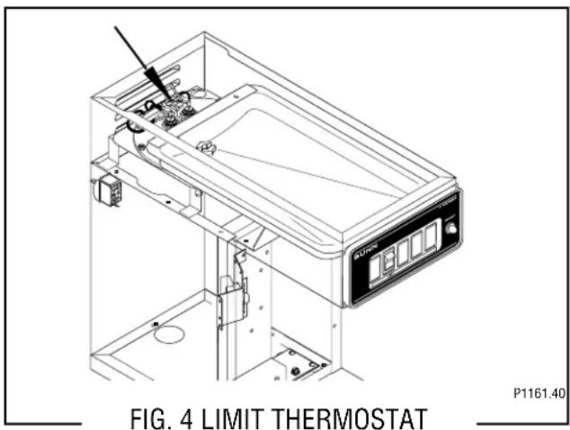
Location:
The limit thermostat is located inside the rear of the hood on the tank lid.
Test Procedures:
- Disconnect the brewer from the power source.
- Disconnect the blue and black wires from the limit thermostat.
- With an ohmmeter, check for continuity across the limit thermostat terminals.
If continuity is present as described, the limit thermostat is operating properly.
If continuity is not present as described, replace the limit thermostat.
Removal and Replacement:
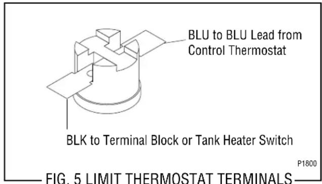
- Remove all wires from limit thermostat terminals.
- Carefully slide the limit thermostat out from under the retaining clip and remove limit thermostat.
- Carefully slide the new limit thermostat into the retaining clip.
- Refer to Fig. 5 when reconnecting the wires.
SERVICE (cont.)
ON/OFF WARMER SWITCH
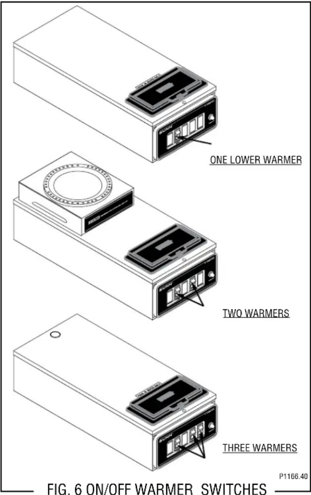
Location:
The ON/OFF warmer switch(es) are located on the front of the hood.
Test Procedure:
- Disconnect the brewer from the power source.
- Viewing the switch from the back, remove the white wire from the upper terminal and the black wire from the center terminal.
- With a voltmeter, check the voltage across the white wire and the black wire. Connect the brewer to the power source. The indication must be:
a) 100 volts ac for two wire 100 volt models.
b) 120 volts ac for two wire 120 volt models. - Disconnect the brewer from the power source.
If voltage is present as described, reconnect the white wire and proceed to #5.
If voltage is not present as described, refer to the Wiring Diagrams and check the brewer wiring harness.
- With the black wire removed, remove the wire from the lower terminal.
- Check for continuity across the center and lower terminal with the switch in the "ON" (upper) position. Continuity must not be present when the switch is in the "OFF" (lower) position.
If continuity is present as described, reconnect the black wire to the center terminal and the remaining wire to the lower terminal.
If continuity is not present as described, replace the switch.
Removal and Replacement:
- Remove the wires from the switch terminals.
- Remove front end cap.
- Compress the clips inside the hood and gently push the switch through the opening.
- Push the new switch into the opening and spread the clips to hold switch in the hood.
- Reinstall front end cap.
- Refer to Fig. 7 when reconnecting the wires.
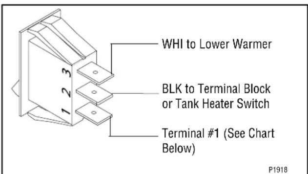
Connect wire to Terminal #1 as follows:
Lower Warmer WHI/RED
One Upper Warmer (Rear) ...... VIO
Two Upper or Side Warmers
(Front)......BRN/BLK
(Rear)......VIO
FIG. 7 ON/OFF SWITCH TERMINALS
SERVICE (cont.)
TANK HEATER
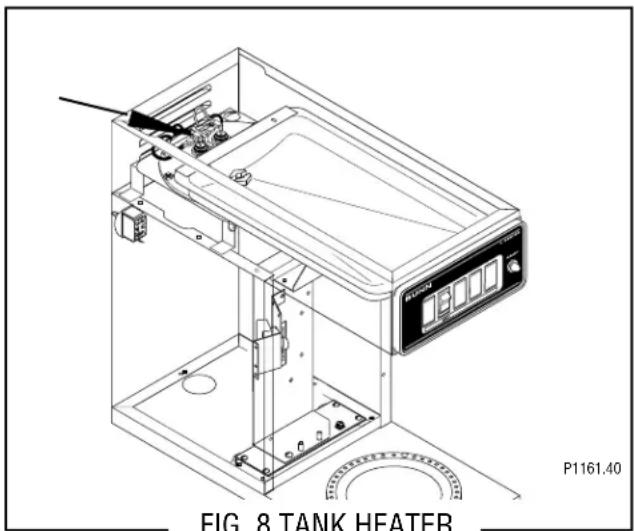
Location:
The tank heater is located inside the tank and secured to the tank lid.
Test Procedures:
- Disconnect the brewer from the power supply.
- With a voltmeter, check the voltage across the black and white wires on the tank heater. Connect the brewer to the power source. The indication must be:
a) 100 volts ac for two wire 100 volt models.
b) 120 volts ac for two wire 120 volt models. - Disconnect the brewer from the power source.
If voltage is present as described, proceed to #4 If voltage is not present as described, refer to the Wiring Diagrams and check wiring harness.
- Disconnect the black wire and the white wire from the tank heater terminals.
- Check for continuity across the tank heater terminals.
If continuity is present as described, reconnect the wires, the tank heater is operating properly.
If continuity is not present as described, replace the tank heater.
NOTE- If the tank heater remains unable to heat, remove and inspect heater for cracks in the sheath.
Removal and Replacement:
-
Remove the tank inlet fitting securing the fill basin to the tank lid, remove fill basin and tank inlet gasket. Set all three parts aside for reassembly.
-
Disconnect the black wire on the limit thermostat from the tank heater switch and disconnect the blue wire from the limit thermostat to the control thermostat.
- Disconnect the black wire and the white wire from the tank heater terminals.
- Remove sprayhead and the hex nut securing the sprayhead tube to the hood. Set aside for reassembly.
- Remove the eight #8-32 nuts securing the tank lid to the tank.
- Remove the tank lid with limit thermostat, sprayhead tube and tank heater
7 Remove the two hex nuts securing the tank heater to the tank lid. Remove tank heater with gaskets and discard. - Install new tank heater with gaskets on the tank lid and secure with two hex nuts.
- Install tank lid with limit thermostat, sprayhead tube and tank heater using eight #8-32 hex nut.
- Secure spayhead tube to hood using a hex nut.
- Install sprayhead.
- Reconnect the wires to the limit thermostat, tank heater and control thermostat. See Limit Thermostat and Control Thermostat sections in this manual when reconnecting wires.
- Install fill basin, secure with tank inlet fitting and gasket.
- Refer to Fig. 9 when reconnecting the tank heater wires.
WHI to WHI Lead on
Power Cord (120V
Models)
WHI to Terminal Block
(White Insert) (100 V
Models)
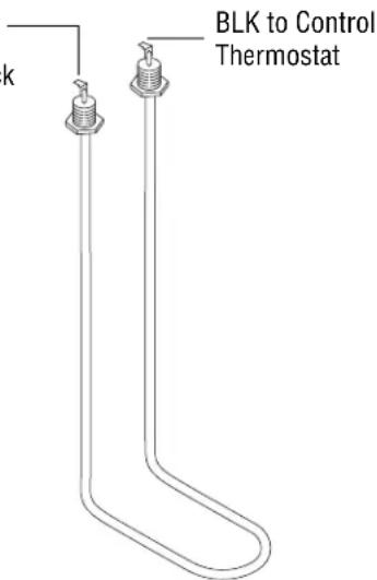
FIG. 9 TANK HEATER TERMINALS
P1163
SERVICE (cont.)
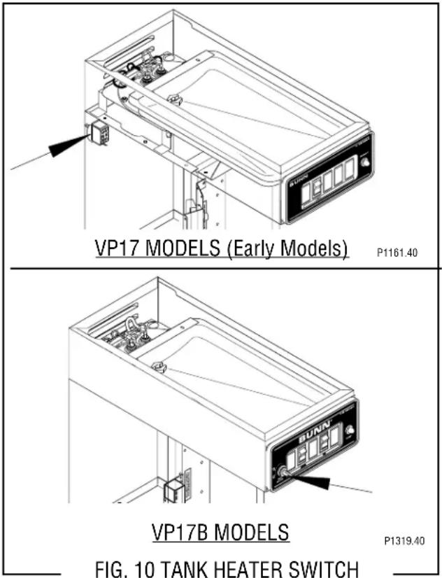
TANK HEATER SWITCH (VP17B and early model VP17)
P1161.40
Location:
On Early VP17 Models the tank heater switch is located on the rear of the brewer on the upper left side of the trunk.
On VP17B Models the tank heater switch is located on left side of the control panel.
Test Procedure:
- Disconnect the brewer from the power source.
- Disconnect the black wire from the limit thermostat.
- With a voltmeter, and with the tank heater switch in the "ON" (upper) position check the voltage between the black wire removed from the limit thermostat and the white wire on the tank heater. Connect the brewer to the power source. The indication must be:
a) 100 volts ac on two wire 100 volt models.
b) 120 volts ac on two wire 120 volt models. - Disconnect the brewer from the power source.
If voltage is present as described, proceed to #5. If voltage is not present as described, refer to the Wiring Diagrams and check the brewer wiring harness.
- Check for continuity between the black wire removed from the limit thermostat and the black insert on the terminal block, with the tank heater switch in the "ON" (upper) position. Continuity should not be present in the "OFF" (lower) position.
If continuity is present as described, the tank heater switch is operating properly.
If continuity is not present as described, replace the tank heater switch.
Removal and Replacement: (VP17)
- Remove the tank inlet fitting securing fill basin to the tank lid. Remove fill basin and gasket. Set all three parts aside for reassembly.
- Remove sprayhead and hex nut securing sprayhead tube to the hood. Set aside for reassembly.
- Disconnect the wires on the limit thermostat and the tank heater.
- Gently pull the thermostat sensor and grommet from the tank lid.
- Insert a tube to the bottom of the tank and syphon ALL of the water out.
- Gently reinstall the thermostat sensor and grommet in the tank lid.
- Remove the two #8-32 screws securing the tank assembly to the hood.
- Lift tank and components out as an assembly and set aside for reassembly.
- Disconnect the two black wires from the tank heater switch.
- Remove the plastic facenut, hex facenut and the switch indicator/guard bracket that secures tank heater switch to the brewer. Remove switch and discard.
- Insert new tank heater switch through the hole in the upper left rear of the trunk and secure with switch indicator/guard bracket, hex facenut and plastic facenut.
- Reconnect the two black wires the tank heater switch terminals.
SERVICE (cont.)
TANK HEATER SWITCH (cont.)
- Set tank assembly inside the hood on mounting brackets and secure with two #8-32 screws.
- Reconnect the wires to the limit thermostat, tank heater and the control thermostat. Refer to Limit Thermostat, Tank Heater and Control Thermostat sections in this manual when reconnecting wires.
- Secure the sprayhead tube to the hood using hex nut.
- Install sprayhead.
- Install fill basin, inlet gasket and secure to tank lid with tank inlet fitting.
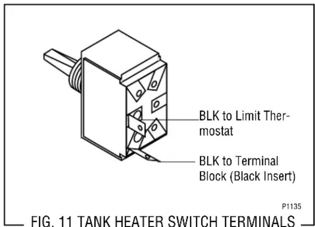
- Refer to Fig. 11 when reconnecting the wires.
Removal and Replacement: (VP17B)
- Remove the tank inlet fitting securing fill basin to the tank lid. Remove fill basin and gasket. Set all three parts aside for reassembly.
- Disconnect the two black wires from the tank heater switch.
- Remove the plastic facenut, hex facenut and the switch indicator/guard bracket that secures tank heater switch to the brewer. Remove switch and discard.
- Insert new tank heater switch through the hole in the lower left of the control panel and secure with swtich indicator/guard bracket, hex facenut and plastic facenut.
- Reconnect the two black wires the to the tank heater switch terminals.
- Install fill basin, inlet gasket and secure to tank lid with tank inlet fitting.
- Refer to Fig. 11 when reconnecting the wires.
SERVICE (cont.)
WARMER ELEMENT(S)
natural_image
Technical line drawing of a BUNN appliance with two circular gauges and control panel (no text or symbols)Location:
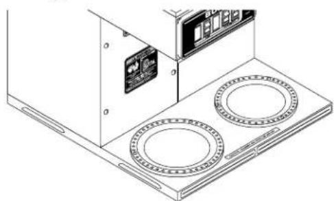
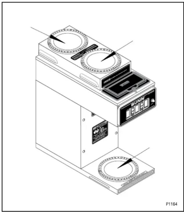
The warmer element(s) is located under the warmer plate.
Test Procedures:
- Disconnect the brewer from the power source.
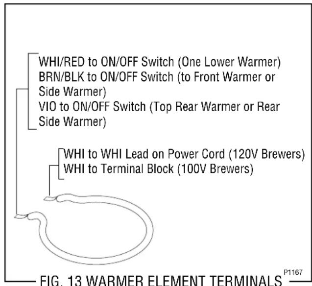
- With a voltmeter, check voltage across the white wire to the power cord and the white/red, brown/black or violet wire to the "ON/OFF" switch, with the "ON/OFF" switch in the "ON" (upper) position. The indication must be:
a) 100 volts ac for two wire 100 volt models.
b) 120 volts ac for two wire 120 volt models.
- Disconnect the brewer from the power source.
If voltage is present as described, proceed to #4. If voltage is not present as described, refer to Wiring Diagrams and check brewer wiring harness.
- Check the continuity across the two terminals on the warmer element.
If continuity is present as described, reconnect the white wire and white/red, brown/black or violet wires on the warmer element.
If continuity is not present as described, replace the warmer element.
Removal and Replacement:
- Remove the three #4-40 screws securing the warmer assembly to the brewer.
- Lift the warmer assembly from the brewer.
- Disconnect the two wires from the warmer element terminals.
- Remove the two #8-32 nuts securing the warmer element to the warmer plate.
- Securely install new warmer element.
- Reconnect the two wires to warmer element terminals.
- Securely install warmer assembly on the brewer.
- Refer to the illustration below when reconnecting the wires.
SCHEMATIC WIRING DIAGRAM
VP17-1/-2/-3
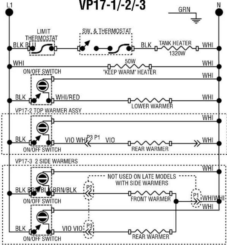
flowchart
graph TD
    subgraph VP17-1/-2/-3
        L1 --> BLK_BLU
        BLK_BLU --> LIMIT_THERMOSTAT
        LIMIT_THERMOSTAT --> BLK
        BLK --> BLK
        BLK --> BLK
        BLK --> BLK
        BLK --> BLK
        BLK --> BLK
        BLK --> BLK
        BLK --> BLK
        BLK --> BLK
        BLK --> BLK
        BLK --> BLK
        BLK --> BLK
        BLK --> BLK
        BLK --> BLK
    end

    subgraph VP17-2_TOP_WARMER_ASSY
        ON/OFF_SWITCH --> BLK
        BLK --> WHI/RED
        WHI/RED --> BLK
        BLK --> BLK
        BLK --> BLK
        BLK --> BLK
        BLK --> BLK
        BLK --> BLK
        BLK --> BLK
        BLK --> BLK
    end

    subgraph VP17-3_2_SIDE_WARMERS
        ON/OFF_SWITCH --> BLK
        BLK --> BLK
        BLK --> BLK
        BLK --> BLK
        BLK --> BLK
        BLK --> BLK
        BLK --> BLK
        BLK --> BLK
        BLK --> BLK
        BLK --> BLK
    end

    L1 -->|GRN| N
    L1 -->|SW. & THERMOSTAT| BLK
    BLK -->|TANK HEATER 1320W| WHI
    BLK -->|50W| "KEEP WARM"HEATER
    BLK -->|LOWER WARMER| WHI
    BLK -->|VIO WHI P3 P1 VIO REAR WARMER| WHI
    BLK -->|NOT USED ON LATE MODELS WITH SIDE WARMERS| P2
    BLK -->|FRONT WARMER| P1
    BLK -->|VIO VIO P3 REAR WARMER| P2
    BLK -->|ON/OFF SWITCH| BLK
    BLK -->|ON/OFF SWITCH| BLK
120 VOLTS AC 2 WIRE + GND SINGLE PHASE
SCHEMATIC WIRING DIAGRAM
VP17-1/-2/-3
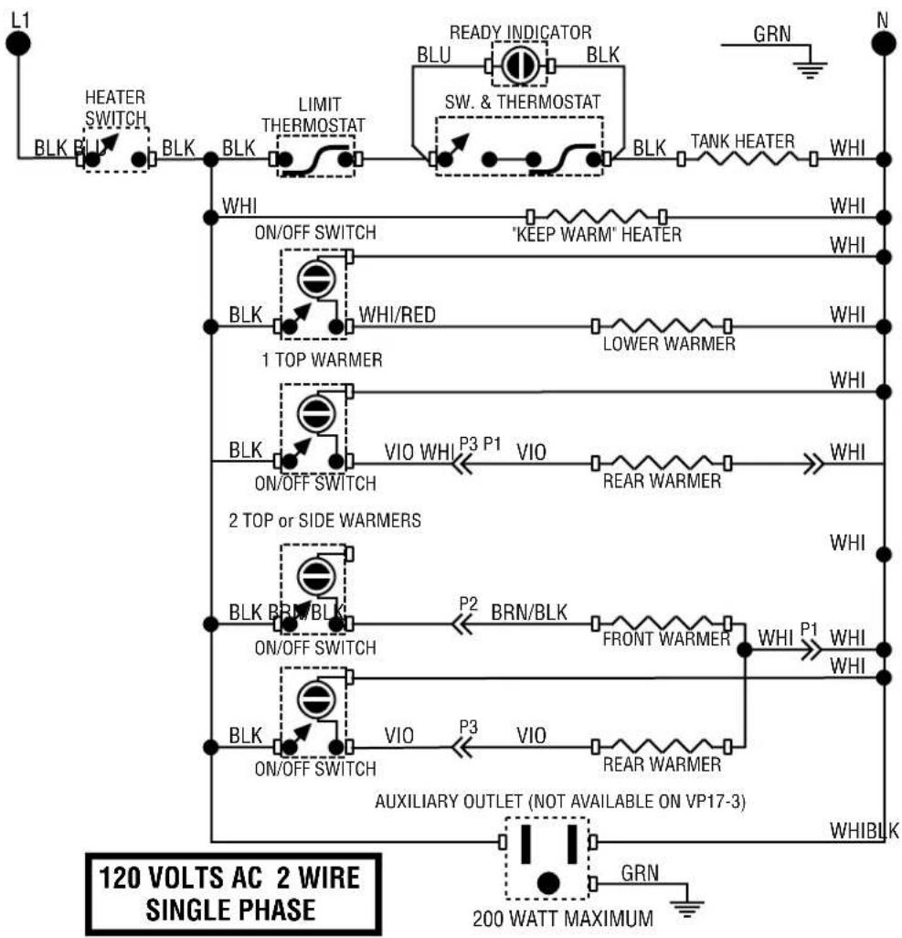
flowchart
graph TD
    A["HEATER SWITCH"] --> B["BLK"]
    B --> C["LIMIT THERMOSTAT"]
    C --> D["READY INDICATOR"]
    D --> E["BLU"]
    E --> F["SW. & THERMOSTAT"]
    F --> G["BLK"]
    G --> H["TANK HEATER"]
    H --> I["WHI"]
    I --> J["ON/OFF SWITCH"]
    J --> K["1 TOP WARMER"]
    K --> L["WHI/RED"]
    L --> M["LOWER WARMER"]
    M --> N["WHI"]
    N --> O["ON/OFF SWITCH"]
    O --> P["VIO WHI P3 P1 VIO"]
    P --> Q["REAR WARMER"]
    Q --> R["WHI"]
    R --> S["2 TOP or SIDE WARMERS"]
    S --> T["BRN/BLK"]
    T --> U["P2 BRN/BLK"]
    U --> V["FRONT WARMER"]
    V --> W["WHI P1 WHI WHI"]
    W --> X["ON/OFF SWITCH"]
    X --> Y["VIO VIO"]
    Y --> Z["REAR WARMER"]
    Z --> AA["AUXILIARY OUTLET (NOT AVAILABLE ON VP17-3)"]
    AA --> AB["WHIBLK"]
    AB --> AC["200 WATT MAXIMUM"]
    AC --> AD["N"]
    style A fill:#f9f,stroke:#333
    style AD fill:#ccf,stroke:#333
SCHEMATIC WIRING DIAGRAM
VP17B-1/-2/-3
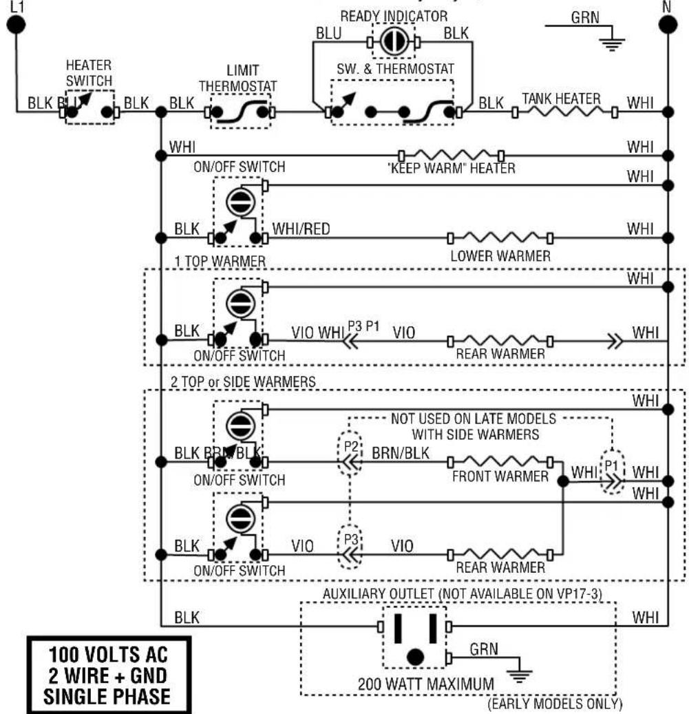
flowchart
graph TD
    A["HEATER SWITCH"] --> B["BLK"]
    B --> C["LIMIT THERMOSTAT"]
    C --> D["SW. & THERMOSTAT"]
    D --> E["BLK"]
    E --> F["TANK HEATER"]
    F --> G["WHI"]
    G --> H["1 TOP WARMER"]
    H --> I["WHI"]
    I --> J["2 TOP OR SIDE WARMERS"]
    J --> K["BRN/BLK"]
    K --> L["P2"]
    L --> M["FRONT WARMER"]
    M --> N["WHI"]
    N --> O["P1"]
    O --> P["WHI"]
    P --> Q["AUXILIARY OUTLET (NOT AVAILABLE ON VP17-3)"]
    Q --> R["GRN"]
    R --> S["200 WATT MAXIMUM"]
    S --> T["(EARLY MODELS ONLY)"]
    U["100 VOLTS AC 2 WIRE + GND SINGLE PHASE"] --> V["BLK"]
    V --> W["ON/OFF SWITCH"]
    W --> X["VIO WHI P3 P1"]
    X --> Y["VIO"]
    Y --> Z["REAR WARMER"]
    Z --> AA["WHI"]
    AB["READY INDICATOR"] --> AC["BLU"]
    AC --> AD["BLK"]
    AD --> AE["SW. & THERMOSTAT"]
    AE --> AF["BLK"]
    AF --> AG["LEEK BLK"]
    AH["GRN"] --> AI["N"]
    AJ["WHI"] --> AK["1 TOP WARMER"]
    AL["WHI"] --> AM["2 TOP OR SIDE WARMERS"]
- DISCONTINUED VERSION The information in this manual is no longer current.
- OPERATING & SERVICE MANUAL
- BUNN-O-MATIC CORPORATION
- INTRODUCTION
- WARRANTY
- USER NOTICES
- 12364.0000
- 00833.0000
- USER NOTICES (cont.)
- WARNING
- 00658.0000
- CAUTION
- 02763.0000
- 37881.0000
- 37881.0002
- ELECTRICAL REQUIREMENTS
- Electrical Hook-Up (Model "B" Only)
- INITIAL SET-UP
- COFFEE BREWING
- CLEANING
- TROUBLESHOOTING
- SERVICE
- COMPONENT ACCESS
- Contents
- SERVICE (cont.)
- CONTROL THERMOSTAT
- Location:
- Test Procedures:
- Removal and Replacement:
- LIMIT THERMOSTAT
- ON/OFF WARMER SWITCH
- Test Procedure:
- Connect wire to Terminal #1 as follows:
- TANK HEATER
- TANK HEATER SWITCH (VP17B and early model VP17)
- Removal and Replacement: (VP17)
- TANK HEATER SWITCH (cont.)
- Removal and Replacement: (VP17B)
- WARMER ELEMENT(S)
- SCHEMATIC WIRING DIAGRAM
- VP17-1/-2/-3
Brand : Bunn
Model : VP17
Category : Coffee maker